Sam RF - Access Control Dormakaba - Free user manual and instructions
Find the device manual for free Sam RF Dormakaba in PDF.


| Product Type | Electronic Access Control System |
| Model | Sam RF |
| Brand | Dormakaba (SAFLOK) |
| System Components | Windows-based software, electronic key encoder, utility device, electronic keys, USB cables, external power supply |
| Software Compatibility | Windows 98 SE, NT 4.0, 2000, XP, Vista, Server 2003 |
| Hardware Requirements | Pentium II or higher, 64 MB RAM, 10 GB hard drive, CD-ROM, USB port |
| Maximum Units | 4000 |
| Maximum Zones | 50 |
| Maximum Suites | 1000 |
| Maximum Common Access Locks | 64 |
| Key Types Supported | Construction, Master, Emergency, Zone, Latch/Unlatch, Inhibit, Guard Check, Diagnostics, Battery Check, Limited Use/Vendor, Resident/Unit |
| Lock Battery Life | Approximately 2 years depending on usage |
| Utility Device Battery Type | Rechargeable NiCad (do not use alkaline) |
| Utility Device Battery Life (full charge) | 3 to 5 hours off base |
| Power Supply for Key Encoder | External AC adapter (included) |
| Connectivity | USB (for key encoder and utility device) |
| Security Features | Password protection, multiple access levels (admin, staff, resident, vendor), inhibit keys, audit trails, lock programming |
| Reporting Capabilities | Unit key history, user key history, keys made, lock audits, limited use audits, transaction history |
| Network Support | Yes, client/remote stations with mapped drive |
| Backup Recommendation | Daily backup of database files |
| Maintenance | Replace lock batteries as needed, update lock clocks annually, clean key contacts |
| Spare Parts | Electronic keys, lock batteries, USB cables, external power supply, utility device, key encoder |
Frequently Asked Questions - Sam RF Dormakaba
User questions about Sam RF Dormakaba
0 question about this device. Answer the ones you know or ask your own.
Ask a new question about this device
Download the instructions for your Access Control in PDF format for free! Find your manual Sam RF - Dormakaba and take your electronic device back in hand. On this page are published all the documents necessary for the use of your device. Sam RF by Dormakaba.
USER MANUAL Sam RF Dormakaba
natural_image
Four metallic pushpins with perforated handles, arranged diagonally (no text or symbols visible)All information contained herein, including but not limited to product pricing and other intellectual property, is confidential and intended for the sole use of the addressee(s) so named. Any misuse of this confidential information contained herein may result in legal action by Computerized Security Systems dba SAFLOK and its parent company.
Table of Contents
Section 1: Introduction
| 1.1 | Welcome to SAM RF | 3 | ||||
| 1.2 | SAM | RF | System | Components | 4 | |
| 1.3 | System | Requirements | 5 | |||
| 1.4 | Quick | Reference | Guide | 6 | ||
Section 2: Installing the SAM RF System
| 2.1 | Installing | the | USB | Driver | Software |
| 2.2 | Installing the SAM RF Software on a Single Station | 10 | |||
| 2.3 | Installing the SAM RF Software on Client/Remote Stations | 13 | |||
| 2.4 | Installing the SAM RF Software with Multiple Databases | 19 | |||
| 2.5 | Installing | the | USB | Driver | Software |
| 2.6 | Installing the Electronic Key Encoder and Utility Device | 31 | |||
| 2.7 | Using | the | SAM | RF | Software |
Section 3: Site Design Process
| 3.1 Understanding the Site Design Process 38 | ||||||
| 3.2 | Entering | Zone | Information | 39 | ||
| 3.3 | Entering | Suite | Information | 41 | ||
| 3.4 | Editing | Suite | Information | 44 | ||
| 3.5 | Entering | Unit | Lock | Information | ||
| 3.6 | Editing | Unit | Lock | Information | 50 | |
| 3.7 | Entering | Common | Access | Area | Information | |
| 3.8 | Confirming | Property | Settings | 54 | ||
Section 4: Management
| 4.1 | Assigning | the | System | Administrator | 58 | |||
| 4.2 | Removing the Default System Administrator | 60 | ||||||
| 4.3 | Creating | Authorization | Groups | 61 | ||||
| 4.4 | Adding | SAM | RF | System | Users | |||
| 4.5 | Adding New Staff to the SAM RF System | 69 | ||||||
| 4.6 | Preventing | Staff | Access | 71 | ||||
| 4.7 | Adding Residents to the SAM RF System | 72 | ||||||
| 4.8 | Deleting | Residents | 74 | |||||
| 4.9 | Adding Vendors to the SAM RF System | 76 | ||||||
| 4.10 | Creating | and | Viewing | Work | Orders | |||
| 4.11 | Editing | Existing | Work | Orders | 82 | |||
| 4.12 | Printing | Work | Orders | 85 | ||||
| 4.13 | Previewing the Work Order Report | 86 | ||||||
| 4.14 | Backing | Up | Data | Files | 87 | |||
| 4.15 | Saving the Backup File Off Your Computer | 88 | ||||||
Table of Contents
Section 5: Keys
| 5.1 | Creating | Additional | Construction | Keys | 8 | ||
| 5.2 | Creating | Master | Keys | 92 | |||
| 5.3 | Creating Additional Duplicate Master Keys | 96 | |||||
| 5.4 | Creating | Emergency | Keys | 97 | |||
| 5.5 | Creating | Additional | Emergency | Keys | 10 | ||
| 5.6 | Creating | Zone | Keys | 101 | |||
| 5.7 | Creating | Additional | Zone | Keys | 105 | ||
| 5.8 | Creating | Latch/Unlatch | Keys | 106 | |||
| 5.9 | Creating | Additional | Latch/Unlatch | Keys | 109 | ||
| 5.10 | Preventing | Access | 110 | ||||
| 5.11 | Creating | Inhibit | Master | Keys | 111 | ||
| 5.12 | Creating | Inhibit | Zone | Keys | 114 | ||
| 5.13 | Creating | Guard | Check | Keys | 116 | ||
| 5.14 | Reading | the | Guard | Check | Keys | 11 | |
| 5.15 | Creating | Diagnostics | Keys | 120 | |||
| 5.16 | Reading | the | Diagnostics | Keys | 122 | ||
| 5.17 | Creating | Battery | Check | Keys | 123 | ||
| 5.18 | Limited | Use/Vendor | Keys | 125 | |||
| 5.19 | Creating | Limited | Use/Vendor | Keys | 126 | ||
| 5.20 | Reading | Limited | Use/Vendor | Keys | 129 | ||
| 5.21 | Creating | Resident/Unit | Keys | 131 | |||
| 5.22 | Creating Additional Duplicate Resident/Unit Keys | 134 | |||||
| 5.23 | Preventing | Resident | Access | 135 | |||
| 5.24 | Replacing | Lost | Resident | Keys | 136 | ||
| 5.25 | Creating a replacement Resident Key | 140 | |||||
Section 6: Locks
| 6.1 | InSync^TM | Locks | 141 | ||||
| 6.2 | Lock | Maintenance | and | Diagnostics | 148 | ||
| 6.3 | Programming | the | Locks | 149 | |||
| 6.4 | Get | Lock | Info | 152 | |||
| 6.5 | Resetting the Time/Date in Lock(s) | 156 | |||||
| 6.6 | Replacing Lock | Batteries | 158 | ||||
| 6.7 | Opening a Lock with a Dead Battery | 159 | |||||
| 6.8 | Reloading | Common | Area Locks | 161 | |||
Section 7: Reports
| 7.1 | SAM RF System Reports-Common Functions | 164 | ||||||
| 7.2 | Unit | Key | History | Report | 166 | |||
| 7.3 | User Key History Report | 168 | ||||||
| 7.4 | Keys | Made | Report | 170 | ||||
| 7.5 | Auditing | Locks | 172 | |||||
| 7.6 | Limited | Use | Audit | Report | ||||
| 7.7 | Transactions Report | 179 | ||||||
Section 8: Frequently Asked Questions and Glossary
| 8.1 | Frequently Asked Questions | 181 |
| 8.2 | Glossary | 183 |
SAM® RF
Operations Manual
Section 1: Introduction
All information contained herein, including but not limited to product pricing and other intellectual property, is confidential and intended for the sole use of the addressee(s) so named. Any misuse of this confidential information contained herein may result in legal action by Computerized Security Systems dba SAFLOK and its parent company.
Section 1: Introduction
1.1 Welcome to SAM ^® RF
SAFLOK's SAM ^ RF system is a sophisticated, yet easy-to-use, electronic locking system, designed to maximize security for apartment homes, timeshares, student housing, assisted-living facilities, military family housing, and similar dwellings.
The SAM RF System includes a Windows-based, password-protected software program that runs on your personal computer (PC), an electronic key-encoding device, a handheld utility device, and electronic keys.
SAM RF eliminates the need for mechanical key-cutting equipment, costly lock replacement, and the risks associated with unauthorized mechanical keys. In addition, SAM RF allows you to authorize, control, and document multiple levels of access to ensure the highest level of security for your property.
Section 1: Introduction
1.2 SAM RF System Components
The SAM RF System includes the following components:
• SAM RF System Software CD (contains the program software and the USB drivers)
• Electronic Key Encoder
• SAM RF System Utility Device
- Electronic Keys – Preprogrammed (Construction) and Un-encoded (Key)
• Power Source for the Electronic Key Encoder
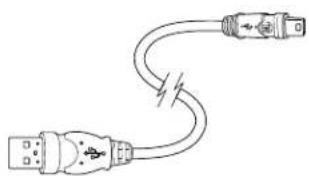
• USB Cable for the Electronic Key Encoder
• USB Cable for the Utility Device
• External Power Supply (EPS)
If a component is missing, please contact your SAM RF sales agent immediately.
Electronic Key Encoder Base

natural_image
Technical line drawing of a mechanical component with mounting holes and internal cavity (no text or symbols)SAM RF System Utility Device

Electronic Keys

Power Source for the Electronic Key Encoder

USB Cable for Electronic Key Encoder
natural_image
Pure electrical circuit lines without any symbolsUSB Cable for Utility Device
External Power Supply for Locks

Section 1: Introduction
1.3 SAM RF System Requirements
The SAM RF System is intended for use on a PC. System requirements include:
- Windows 98 SE, NT 4.0, 2000, XP, Vista, or Server 2003
- A minimum of Pentium II or greater PC processor, 64 MB RAM, 10-gigabyte hard drive, CD-ROM drive, 3.5-inch floppy disk drive, and a V.90 internal or external modem
- At least one USB port for connecting the electronic key encoder device (a USB cable is provided)
- Anti-virus protection program (e.g., Norton AntiVirus, McAfee VirusScan)
- UPS and surge protection with an equipment warranty is suggested
- PC Anywhere Version 9.2 or greater for remote access or Virtual Private Network (VPN) access (highly recommended)
Note: Due to the wide performance variability of hardware from different manufacturers, SAFLOK cannot guarantee software compatibility with all computers. If you require a list of computers that SAFLOK has tested and deemed software-compatible, please contact SAFLOK technical support at 800.999.6213.
Section 1: Introduction
1.4 Quick Reference Guide
Making New Resident Keys
- At the main SAM RF screen, click Keys.
- Click Create.
- Click Resident Key.
- Check New Key.
- Select Unit Number.
- Check the Key Expires box and set the expiration date. This is optional.
- Click the button to the right of The Key Is Assigned To.
- Select Resident and click OK.
- Highlight the name of the resident and click Select.
- Back at the Create Resident Key screen, check or uncheck the box next to the common access lock(s) you wish to add or remove from the resident key.
- Insert the key into the encoder.
- Click OK. When the key is encoded the screen will display "The write operation was successful."
- Click OK and Cancel to return to the main screen.
Making Duplicate Resident Keys
- At the main SAM RF screen, click Keys.
- Click Create.
- Click Resident Key.
- Check Duplicate Key.
- Select Unit Number.
- Check the Key Expires box and set the expiration date. This is optional.
- Click the button to the right of the Key Is Assigned To.
- Select Resident and click OK.
- Highlight the name of the resident and click Select.
- Back at the Create Resident Key screen, check and uncheck the box next to the common access locks you wish to add or remove from the Resident key.
- Insert the key into the encoder.
- Click OK. When the key is encoded, the screen will display "The write operation was successful."
- Click OK and Cancel to return to the main screen.
Invalidating a Lost Resident Key
- Read each of the keys that were issued to the resident. This will provide the key's ID and assigned name.
- Make an Inhibit Resident key for the key that was lost.
- Use the Inhibit Resident key in the unit and all common access locks to invalidate the key that was lost.
Reading Keys
- At the main SAM RF screen, click Keys.
- Insert the key into the encoder.
- Click Read.
- The Key Read screen will appear. When finished reviewing the information, click Close.
Section 1: Introduction
Quick Reference Guide (continued)
Making an Inhibit Resident Key
- At the main SAM RF screen, click Keys.
- Click Create.
- Click Inhibit Resident Key.
- Select the Unit Number.
- Select the ID(s) to inhibit.
- Check the button to the right of The Key is Assigned To.
- Select Staff or Resident and click OK.
- At the Staff or Resident List screen, highlight the name of the person you want to assign the key to and click Select.
- The screen will return to the Create Inhibit Resident screen. Insert key into the encoder and click OK. When the key is encoded, the screen will display "The write operation was successful."
- Click OK and Cancel to return to the main screen.
- This key will need to be used in the unit and common area lock(s) it was assigned to in order to invalidate the lost key.
Adding a New Resident
- At the main SAM RF screen, click Maintenance.
- Click Residents.
- Highlight the Unit Number and click Add.
- At the Resident Form screen, type the last name, first name, middle initial, phone number(s), and any additional notes, then click Save.
- At the Unit Resident List screen, click Close.
Making Limited Use Keys
- At the main SAM RF screen, click Keys.
- Click Create.
- Click Limited Use Key.
- Check the box next to the Unit Lock(s) you want the key to open.
- Check the box next to the Common Access Lock(s) you want the key to open.
- If you are only selecting one unit and want the key to only open the door once, check the box next to One Shot Key.
- Set the Valid Date.
- Set the Expiration Time.
- Click the button to the right of The Key Is Assigned To.
- Select the Staff, Resident, or Vendor option and click OK.
- Highlight the name of the Staff, Resident, or Vendor and click Select.
- Insert the key into the encoder.
- Click OK. When the key is encoded, the screen will display "The write operation was successful."
- Click OK and Cancel to return to the main screen.
Section 1: Introduction
Quick Reference Guide (continued)
Auditing Locks
- At the main SAM RF screen, click Utility Device.
- Click Download Audit Trail from Lock(s).
- Wait for the computer screen to display "The write operation was successful," then click OK.
- Disconnect the USB cable from the back left side of the electronic key encoder base. Keep the other end connected to the top of the Utility Device.
- Remove the Utility Device from the base and take it to the lock.
- Remove the rubber cover on the lock's receptive port and connect the USB cable to the receptive port.
- The utility device will beep two times and display "Operation completed." Remove the USB cable from the lock and replace the rubber cover on the receptive port.
- Return the Utility Device to the base and reconnect the USB cable to the back left side of the electronic key encoder.
- At the main SAM RF screen, click Utility Device.
- Click Upload Audit Trail Info From Utility Device.
- When the Confirmation screen appears, click Yes.
- When the Success screen appears, click OK.
- At the main SAM RF screen, click Reports.
- Click Lock Audits.
- When the Lock Audit Report screen appears, highlight the unit number and click View Report.
- When the Output Options screen appears, select Preview and click OK.
- The report will appear on the screen. When finished reviewing, click File then Exit.
- The Output Options screen will appear again. Click Close.
Programming Locks
- At the main SAM RF screen, click Utility Device.
- Click Program Locks.
- At the Program Locks screen, check box next to the lock(s) you wish (up to 100) to program and click OK.
- Wait for the computer screen to display "The write operation was successful." then click OK.
- Disconnect the USB cable from the back left side of the electronic key encoder base. Keep the other end connected to the top of the Utility Device.
- Remove the Utility Device from the base and take to the lock.
- Press Home/0 to display the lock numbers and select the lock number you wish to program.
- Remove the rubber cover on the lock's receptive port and connect the USB cable to the receptive port.
- The Utility Device will beep two times and the Utility Device will display "Operation completed." Remove the USB cable from the lock and replace the rubber cover on the receptive port.
- Return the Utility Device to the base and reconnect the USB cable to the back left side of the electronic key encoder.
Note: If you are unable to perform any of these transactions, please see your system administrator (you may not have permission to perform these tasks). Please consult the following sections for more detailed information.
SAM® RF
Operations Manual
Section 2: Installing the SAM RF System
All information contained herein, including but not limited to product pricing and other intellectual property, is confidential and intended for the sole use of the addressee(s) so named. Any misuse of this confidential information contained herein may result in legal action by Computerized Security Systems dba SAFLOK and its parent company.
Section 2: Installing the SAM RF System
2.1 Installation Overview
The SAM RF system is loaded from one CD. Be sure to install the SAM RF System Software first, followed by the SAM RF System USB Drivers.
Before beginning the installation process, determine how the SAM RF system will be installed:
- If the SAM RF system will be installed on a single station, proceed to Section 2.2. Most properties choose to run the software from a single computer.
- If the SAM RF system will be installed on a network, skip ahead to Section 2.3.
• If the SAM RF system will operate with multiple databases, skip ahead to Section 2.4
Once the SAM RF system is installed, complete Section 2.6 "Installing the Electronic Key Encoder and Utility Device."
Note: Please confirm that all components are present (refer to Section 1.2 "SAM RF Components") before you proceed.
Important: Do not connect the key encoder and utility device cables until all software is installed.
Section 2: Installing the SAM RF System
2.2 Installing the SAM RF Software on a Single Station
Note: To operate the SAM RF System from a remote computer, go to Section 2.3 "Installing SAM RF on Client/Remote Stations".
Important: Do not connect the key encoder and utility device until all software is installed.
- Insert the CD into your CD-ROM drive on your PC and the Setup program should launch automatically.
Note: If the Setup program does not auto-start, go to the Start menu and click Run. Click Browse to find the SAMrfSetup.exe file located on the CD-ROM drive and double click on it. Back at the Run PC dialog box, click OK.
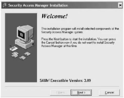
- Click Next at the Welcome PC dialog box.
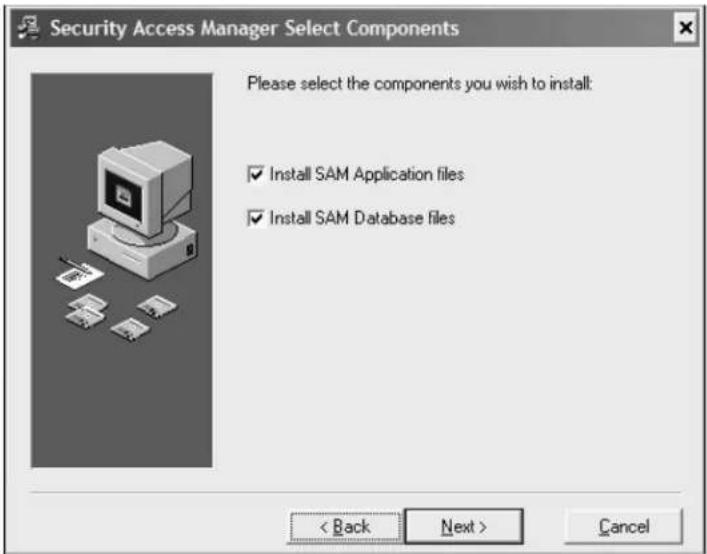
- Check both boxes to install the SAM application files and the database files, then click Next at the Select Components PC dialog box.
Important: Check both boxes on the Select Components PC dialog box before continuing with the installation process.

Section 2: Installing the SAM RF System
Installing the SAM RF Software on a Single Station (continued)
- Click Next at the Select Destination Directory PC dialog box to continue the installation process. The SAM RF System database will automatically install into the default folder location (C:\Program Files\SAMrf).
Note: You may choose to install the program into a different folder location; however, for service purposes, it is recommended that you keep the default location for the SAM RF System to allow our technical service associates to better assist you.
-
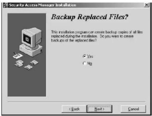
Select Yes, then click Next at the Backup Replaced Files PC dialog box.
-
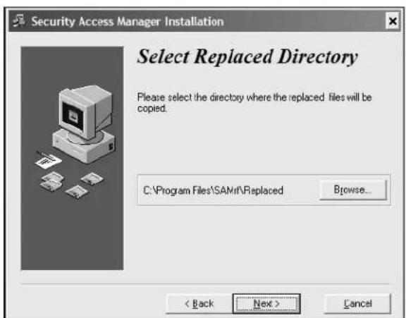
Click Next at the Select Replaced Directory PC dialog box.
Note: Even if you are installing the software for the first time, we recommend that you accept these defaults.


Section 2: Installing the SAM RF System
Installing the SAM RF Software on a Single Station (continued)
- Click Next at the Ready to Install PC dialog box.

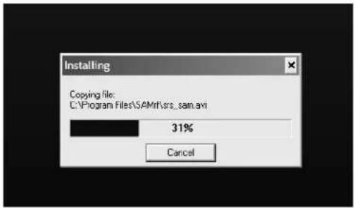
- Installation progress will display in the Installing PC dialog box.
- Click Finish at the Installation Completed PC dialog box. The installation process is now complete.

- Remove the SAM RF System software CD from the CD-ROM drive on your PC. Retain the CD in a safe place in case software reinstallation is necessary.
Skip ahead to Section 2.5 to install the USB drivers.
Section 2: Installing the SAM RF System
2.3 Installing the SAM RF Software for Client/Remote Stations
Important: Do not connect the key encoder and utility device until all software is installed.
-
Before installing the SAM RF System software on a remote computer, you must complete the following:
-
Install the SAM application and database on the SAM RF server (the computer where you intend to load the SAM RF database files).
- Share the SAMrf directory on the SAM RF server so remote users can link to the database. The path to this directory on the SAM server is C:\Program Files\Samrf.
-
Map a network drive on the remote computer to the SAM RF server's SAMrf directory.
-
Insert the SAM RF System CD into your CD-ROM drive. The Security Access Manager Installation program will launch automatically.
Note: If the Setup program does not auto-start, go to the Start menu and click Run. Click Browse to find the setup.exe file located on the CD-ROM and double click it. Back at the Run PC dialog box, click OK.
- Click Next at the Welcome PC dialog box.

- Click Next at the Select Components PC dialog box.
Important: DO NOT click the box next to "Install SAM Database files." Only "Install SAM Application files" should be selected.

Section 2: Installing the SAM RF System
Installing the SAM RF Software for Client/Remote Stations (continued)
- Click Next to accept the default directory path on the Select Destination Directory PC dialog box.

- Click Next at the Backup Replaced Files PC dialog box.

- Click Next at the Select Replaced Directory PC dialog box.
Section 2: Installing the SAM RF System
Installing the SAM RF Software for Client/Remote Stations (continued)
- Click Next at he Ready to Install PC dialog box to start the installation.

- The Installing PC dialog box will appear to show the progress.

- Click Finish at the Installation Completed PC dialog box.

Section 2: Installing the SAM RF System
Installing the SAM RF Software for Client/Remote Stations (continued)
- Double click the on the SAM RF icon to launch the program. The SAM RF System shortcut can be found on the desktop, or you may follow the path C:\Program Files\Samrf to find the SAM RF System executable file named: SRS_SAMrf.EXE.

- Click OK at the first warning PC dialog box.

- Click OK to continue at the second warning PC dialog box.

- Click OK to continue at the LAN Warning PC dialog box.

Section 2: Installing the SAM RF System
Installing the SAM RF Software for Client/Remote Stations (continued)
- Double click the mapped network drive that links to the SAM RF System database files. In this example, the mapped drive is S:\SAMRF Servers SAM RF Directory.
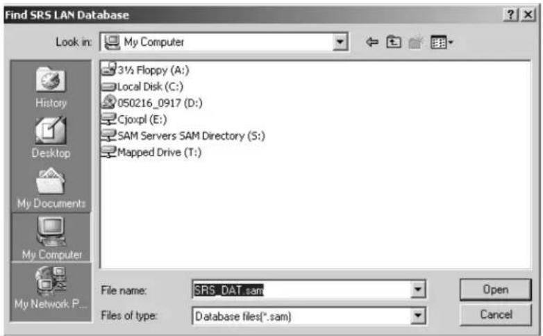
- At the SAM RF Servers SAM RF Directory, click on the Data folder and click Open.

Section 2: Installing the SAM RF System
Installing the SAM RF Software for Client/Remote Stations (continued)
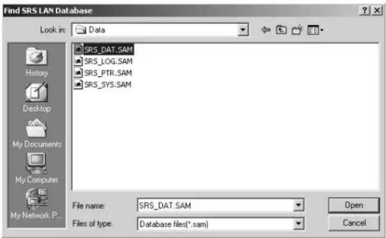
- The browser window will display the SAM RF System database files.
Click on SRS_DAT.SAM, and then click Open.

Skip ahead to Section 2.5 to install the USB drivers.
Clicking on the file will display the Initialization screen, or SAM RF System main menu. Like most Windows-based programs, pull-down menus appear in the upper left area of the screen, and only those features that are active and accessible will be highlighted.
Until you log on to the SAM RF System, only the File menu will be active. All other features of the system will be inaccessible.
The installation and configuration of the remote SAM RF System is complete. Click File and then Logon to proceed to the Logon screen.
Remove the SAM RF System software CD from the CD-ROM drive on your PC. Retain the CD in a safe place in case software reinstallation is necessary.
Section 2: Installing the SAM RF System
2.4 Installing the SAM RF System Software with Multiple Databases
This section explains how to install multiple SAM RF databases on the SAM RF server (the computer where you intend to load the SAM RF database files). This process should only be done if your organization has requested and/or received separate databases.
Important: Do not connect the key encoder and utility device until all software is installed.
- Insert the SAM RF software CD into the SAM RF server. The Security Access Manager Installation program should launch automatically and the Welcome PC dialog box will appear.
Note: If the setup program does not auto-start, go to the Start menu and click Run. Click Browse to find the setup.exe file located on the CD-ROM and double click it. Back at the Run PC dialog box, click OK.
- Click Next at the Welcome PC dialog box.

- Be sure that both components are selected and click Next to continue.
Important: Check both boxes before continuing with the installation process.
Section 2: Installing the SAM RF System
Installing the SAM RF System Software with Multiple Databases (continued)
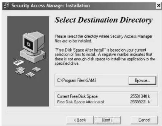
- Click Browse at the Select Destination Directory PC dialog box.
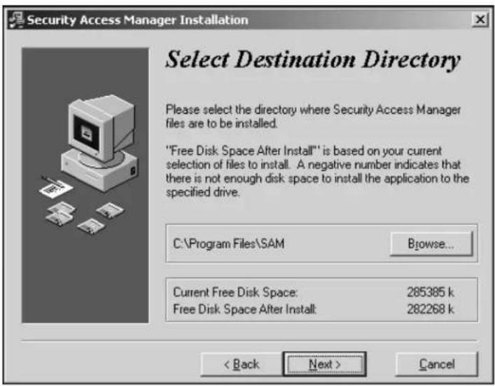
- Click in the blank area directly to the right of the default installation path, C:\Program Files\SAMrf. Next, type a name that will uniquely identify the first SAM directory, which will automatically be created during the installation process. The following are directory names to consider:
C:\Program Files\SAMrf1
C:\Program
Files\SAMrfDB1
C:\Program
Files|SAMrfTroySite
- Click OK to continue.

Section 2: Installing the SAM RF System
Installing the SAM RF System Software with Multiple Databases (continued)
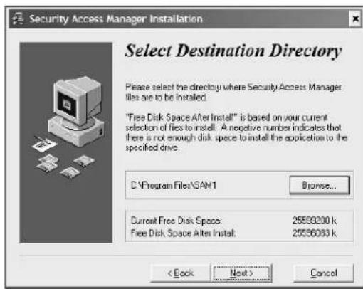
- To the left of the Browse button is the new destination for the first SAMrf directory. For this example, C:\Program Files\SAMrf1 is shown. Click Next to continue.
- Click Next at the Select Database Directory PC dialog box.

- Click Next at the Backup Replaced Files PC dialog box to accept the default setting.

Section 2: Installing the SAM RF System
Installing the SAM RF System Software with Multiple Databases (continued)
- Click Next at the Select Replacement Directory PC dialog box.

- Click Next at the Ready to Install PC dialog box to start the installation process.
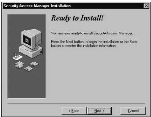
- The system displays the progress.

Section 2: Installing the SAM RF System
Installing the SAM RF System Software with Multiple Databases (continued)
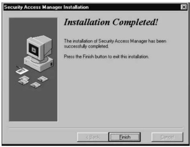
- Click Finish at the Installation Completed PC dialog box.
-
On the desktop of the SAM RF server, rename the SAM RF shortcut to the name of your first SAM RF directory. In this example, SAMRF1 is the name for the first SAM RF directory and the desktop shortcut.
-
Installation of the second SAM RF application and database is much like the first. Eject the first SAM RF System software CD from the computer then insert the second SAM RF System software CD into the computer. Repeat this installation process until the Select Destination Directory PC dialog box appears (Step 4), then jump to Step 15.
-
Click Browse to display a browser window, which allows you to change the installation directory for the second SAM RF application and database files.

Section 2: Installing the SAM RF System
Installing the SAM RF System Software with Multiple Databases (continued)
- Click in the blank area directly to the right of the default installation path (C:\Program Files\SAMrf) and type a name that will uniquely identify the second SAM directory, which will automatically be created during the installation process. The following are directory names to consider:
C:\Program Files\SAMrf2
C:\Program
Files\SAMrfDB2
C:\Program
Files\SAMrfVegasSite
-
Click OK to continue.
-
Review the information displayed at the Select Destination Directory. Your new directory is indicated to the left of the Browse button. Click Next to continue.
-
Click Next to accept the default setting on the Select Database Directory PC dialog box.


Section 2: Installing the SAM RF System
Installing the SAM RF System Software with Multiple Databases (continued)
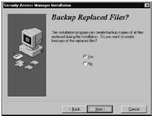
- Be sure that Yes is selected, then click Next at the Backup Replaced Files PC dialog box.
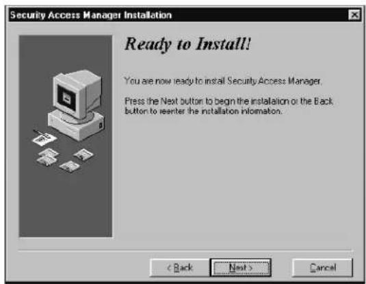
- Click Next to start the installation process at the Ready to Install PC dialog box.
- The Installing PC dialog box will appear to show the progress.

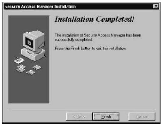
- Click Finish at the Installation Completed PC dialog box.
Section 2: Installing the SAM RF System
Installing the SAM RF System Software with Multiple Databases (continued)
- After all SAM RF applications and databases are installed, the SAM RF server's desktop should display all SAM shortcuts.
To complete this part of the second SAM RF application and database installation, go to the desktop of the SAM server, and then rename the SAM RF shortcut to the name of your second SAM RF directory. In this example, SAMRF2 is the name for the second SAM RF directory and the desktop shortcut.
- Click either or both SAM RF icon(s) to display the SAM RF main menu screen.
- On the main menu screen, click File and then Logon to proceed to the logon screen.

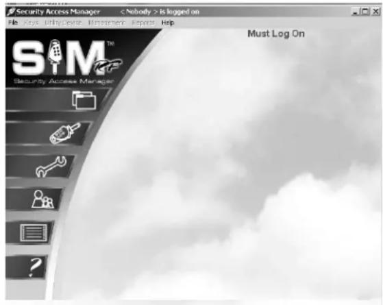
This will display the initialization screen, or SAM RF System main menu. Like most Windows-based programs, pull-down menus appear in the upper left area of the screen, and only those features that are active and accessible will be highlighted. Until you fully log on to the SAM RF System, only the File menu will be active. All other features of the system will be inaccessible.
Continue to Section 2.5 to install the USB drivers.
Section 2: Installing the SAM RF System
2.5 Installing the USB Driver Software
After the SAM RF system software is installed, you must install is the CP2101 USB driver software.
Important: Do not connect the key encoder and utility device until all software is installed.
Note: Keep the default settings as you install the USB driver software unless you are directed otherwise by SAFLOK technical support.
Important: Do not connect the key encoder and utility device until all software is installed.
- With the CD still in the CD-ROM, ....explore the CD-ROM drive.
- Go to your CD-ROM drive and double click on the CP2101 Custom Install icon.
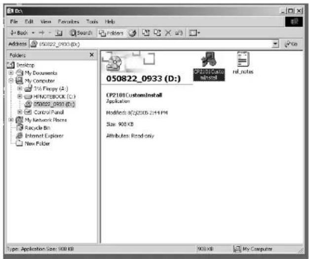
- Click Next at the bottom of the CP2101 Custom Setup Warning PC dialog box.

Section 2: Installing the SAM RF System
Installing the USB Driver Software (continued)
- Click Next at the bottom of the CP2101 Custom Setup Utility PC dialog box that begins with the Uninstall File.
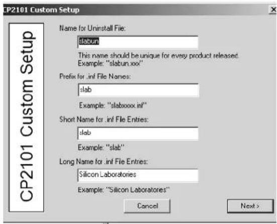
- Click Next at the bottom of the CP2101 Custom Setup PC dialog box that indicates the COM and USB devices.
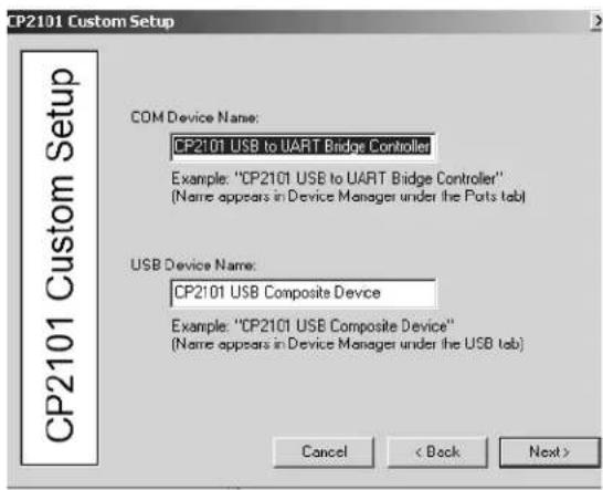
- Click Next at the bottom of the third CP2101 Custom Setup PC dialog box with the vendor ID and the product ID.

Section 2: Installing the SAM RF System
Installing the USB Driver Software (continued)
- Click Next at the bottom of the CP2101 Custom Setup PC dialog box with the preinstaller options.

- Click Next at the bottom of the CP2101 Custom Setup PC dialog box that indicates the directory location.

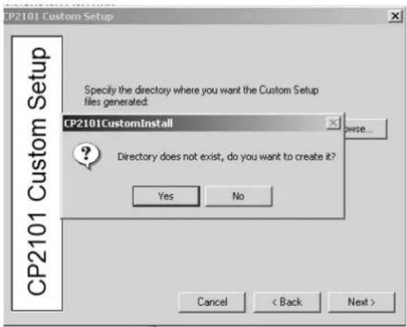
- Click Yes at the "Directory does not exist, do you want to create it?" message. Then, click Next.
Section 2: Installing the SAM RF System
Installing the USB Driver Software (continued)
- Click Finish at the final CP2101 Custom Setup PC dialog box.

- Click OK when the PC dialog box will displays, "File Successfully Generated."

- Remove the CP2101 USB driver software CD from the CD-ROM drive on your PC. Retain the CD in a safe place in case software reinstallation is necessary.
Section 2: Installing the SAM RF System
2.6 Installing the Electronic Key Encoder and Utility Device
After the SAM RF software and the USB Drivers are installed, you will need to install is the electronic key encoder that connects to your PC using its USB cable. The installation of the electronic key encoder will also allow the utility device to communicate with the PC. When the utility device sits in the base of the electronic key encoder, its batteries recharge for operations at the InSync™ locks throughout your property.
SAM RF System USB Cable Connections

- Plug the power source into an electric socket in the wall or a power strip, then plug the power source into the key encoder base.
- Plug the electronic key encoder USB cable into the base of the electronic key encoder and connect the other end to the USB port of your PC.
- Connect the USB cable between the electronic key encoder base and the utility device.
Section 2: Installing the SAM RF System
Installing the Electronic Key Encoder and Utility Device (continued)
- Be sure that the utility device is docked on the key encoder and the key encoder is connected and plugged in.
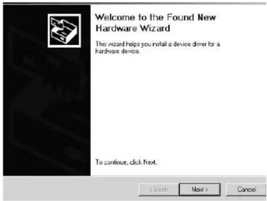
- Click Next at the Welcome to the Found New Hardware Wizard PC dialog box, which will launch automatically.
-
Click Next at the Install Hardware Device Drivers PC dialog box.
-
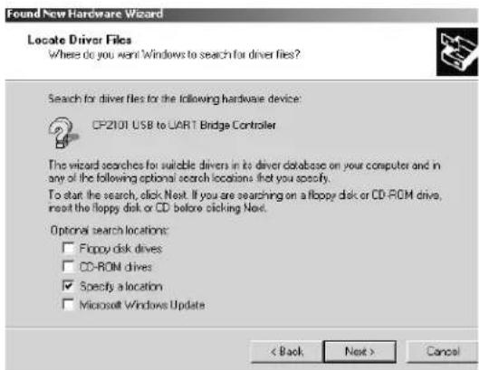
Click Next at the Locate Driver Files PC dialog box.

Section 2: Installing the SAM RF System
Installing the Electronic Key Encoder and Utility Device (continued)
- Click Next at the Found New Hardware Wizard Default PC dialog box.

- Click Next at the Driver Files Search Results PC dialog box.
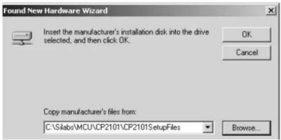
- Click Finish at the Completing the Found New Hardware Wizard Installation Complete PC dialog box.

- In most cases, you will be prompted to repeat this procedure, starting again with Step 5 on page 32.
Section 2: Installing the SAM RF System
Installing the Electronic Key Encoder and Utility Device (continued)
- On your PC desktop, right click on the My Computer icon. This will bring up a pull-down menu. Click Properties.

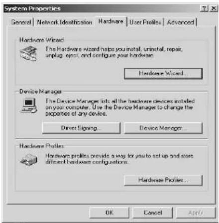
- Click on the Hardware tab, then click on Device Manager at the System Properties PC dialog box.
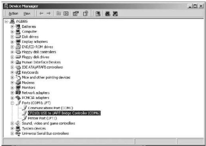
- Click on the Plus Sign (+) next to Ports at the Device Manager PC dialog box.
- Important: A series of ports will appear. Take note of the COM port number next to CP2101USB to UART Bridge Controller. Later, you will need to assign this number in the SAM RF software.
- Click on the X in the upper right-hand corner to close the Device Manager PC dialog box.
Section 2: Installing the SAM RF System
Installing the Electronic Key Encoder and Utility Device (continued)
- Double click on the SAM RF icon on your PC desktop to open the SAM RF program. You will receive a prompt to log on.
- Log on to the system as discussed in Section 2.7 "Using the SAM RF Software".

- Point to the Management pull-down menu and select Terminal Settings.
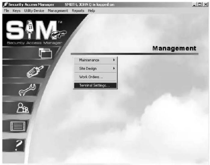
- Type the COM port number you recorded in Step 14. The electronic key encoder and utility device are now ready for use.
- Click OK to complete the installation of the key encoder and utility device.

Section 2: Installing the SAM RF System
2.7 Using the SAM RF Software
Launching SAM RF
A shortcut to SAM RF has been placed in the Start menu. To start the program, go to your computer's Start menu and select SAM RF to launch the program.
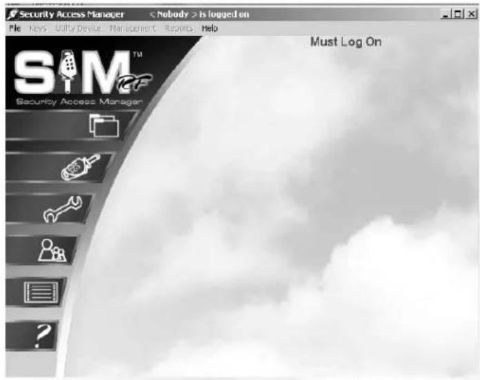
This will display the Initialization screen dialog box, or SAM RF System main menu. Like most Windows-based programs, pull-down menus appear in the upper left area of the screen, and only those features that are active and accessible will be highlighted. Until you fully log on to the SAM RF System, only the File menu will be active. All other features of the system will be inaccessible.
Logging on to SAM RF
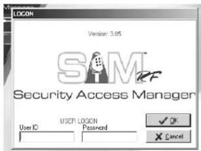
The SAM RF system offers two convenient menu access options. You may access items from the word menu at top of the screen or you may access the items from the icon menu on the left hand side of screen. To start the log-on process, point to the File pull-down menu and select Log On...

When the SAM RF System is started for the first time, both the User ID and Password are the same: "ADMIN." Type "ADMIN" in the User ID field and the Password field and click OK (or press ENTER).
Section 2: Installing the SAM RF System
Using the SAM RF Software (continued)
Once you are logged on to the SAM RF System, all pull-down menus will be active, allowing you full access to all the program's features. The name of the person who is currently logged on to the SAM RF System will appear at the top of the PC dialog box.

SAM RF will automatically log off the current user if the system remains idle for more than five minutes. The user will then have to log back on to the system using his or her user ID and password.
Once you have full access to all the program's features, you can complete the site design process, configuring the SAM RF System specifically for your property. Although this takes some time, once it is configured, the information contained in the system will require only minor changes in the future.
Configuring the SAM RF System entails the following:
- Adding new SAM RF System users, or employees who will have access to and use of the SAM RF System. SAM RF allows you to assign varying levels of access to the system's many features.
- Setting up zones that represent individual buildings or other areas within your property.
- Inputting unit numbers, either individually or by group.
- Setting up any common access locks, for areas such as for the pool gate or laundry doors.
- Setting up any suite doors that provide access to up to ten unit doors.
SAM® RF
Operations Manual
Section 3: Site Design Process
All information contained herein, including but not limited to product pricing and other intellectual property, is confidential and intended for the sole use of the addressee(s) so named. Any misuse of this confidential information contained herein may result in legal action by Computerized Security Systems dba SAFLOK and its parent company.
Section 3: The Site Design Process
3.1 Understanding the Site Design Process
The site design process refers to entering information about your property into the SAM RF System. This information generally includes the actual units and their designations (e.g., 1A, Apartment 211, Building A, Unit 101, etc.), any common access areas such as a pool or laundry room, any zones or suites, and more.
It is important to be accurate and thorough when entering information about your property into the SAM RF System. The configuration of your locks and the programming of your keys are dependent upon accurate site design information. Although it may take a considerable amount of time to perform the site design process, changes to this information will not likely be required in the future.
Note: You may have had SAFLOK create your site design. If so, you will not need to create one. However, to reconfigure your site design to accommodate the addition of new units or other changes to your property locks that may impact your site design, you will need to use the following instructions.
Section 3: The Site Design Process
3.2 Entering Zone Information
The site design process begins by entering information about any zones your property may have. Zones are separate buildings or groups of locks. The SAM RF System allows you to group up to 50 zones. A Zone key is the key that you will give to employees to allow them to gain access only to those units (and any common access areas) within the zone or zones for which they have authorization.
If your property is only a single building, you may set up each floor as a different zone, or you can choose not to set up zones at all. In this case, go to the next subsection "Entering Suite Lock Information."
- Click on the Management menu at the top of the window or the Management icon.
- Point to Site Design, then select Zones...
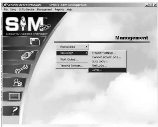
- To begin entering zone information for your property at the Zone Configuration PC dialog box, click on 1: ZONE 01 and then click Edit.

Section 3: The Site Design Process
Entering Zone Information (continued)
- In the Name field, highlight over ZONE 01 and type in an appropriate name for your first zone, such as Building A or Floor 01. Make sure that the Active box is checked, and then click OK.
IMPORTANT: If you are using numbers, be sure to use only two-digit numbers by including a 0 in front of any single-digit numbers. For example, use Building 01 (not Building 1), Building 02 (not Building 2), Building 10, etc. This will ensure that the zones are listed in the proper order later in the site design process.

- Back at the Zone Configuration PC dialog box, the changes you just made to 1: ZONE 01 will appear in boldface type. Continue entering zone information for your property by clicking on 2: ZONE 02, etc., and then clicking Edit to display the Zone Edit PC dialog box.
- When you have finished designating the appropriate number of zones for your property, click Save to store the information in the SAM RF System.
To confirm that all zone information has been saved, go back to the Zone Configuration PC dialog box. The names of the zones you just registered should no longer appear in boldface type.
Section 3: The Site Design Process
3.3 Entering Suite Information
The next step in the site design process is to input information about any suites your property may have. Suite locks allow access to smaller groupings of units, where up to ten units are accessed through one door. An example of a suite lock may be an entry door to an apartment with two or more unit locks inside on bedroom doors. The SAM RF System allows you to add up to 1000 suites. When you eventually make unit keys, the keys for any units within suites will be programmed to open both the suite door as well as their own individual unit doors – not all the unit doors within the suite.
If your property does not have suites, skip to Section 3.5.
- Click on the Management menu at the top of the window or the Management icon.
- Point to Site Design, then select Suite Locks.

- Unlike in the Zone Configuration PC dialog box, no suites are pre-listed at the Suite Configuration PC dialog box. To begin entering suite information into the SAM RF System, click Add.

Section 3: The Site Design Process
Entering Suite Information (continued)
- At the Suite Add PC dialog box, type in the designation for your first suite at the Suite Name field. For example, you could type "Suite 01," "Suite A," "West Wing," "Suite 101," etc., then click Add.
The suite you just named will appear in the list box below the Suite Name field.

- You can continue adding additional suites in this manner, or you may add a range of suite numbers to the system, as long as they are in the same zone.
To add a range of suite numbers from the same zone into the system, type the word SUITE (or another appropriate name such as Building A, Suite) in the Suite Name box, then go to the Add Name Range area.
To add numeric information BEFORE the information entered into the Suite Name box, click the open circle in front of Prefix; to add the numeric information AFTER the information entered into the Suite Name box, click the open circle in front of Postfix. Enter the range of suite numbers, such as 01 to 20, and click Add. The range of suites you just designated will appear in the list box below the Suite Name field.

Note: If you are using numbers, be sure to use only two-digit numbers by including a 0 in front of any single-digit numbers. For example, use Suite 01 (not Suite 1), Suite 02 (not Suite 2), Suite 10, etc. to ensure that the suites are listed in the proper order later in the site design process.
Note: If the information in the Suite Name box does not appear as you had intended, you can delete the entries individually by clicking on a single entry and clicking Remove. To delete all the entries at one time, click on the first entry, holding down the
Section 3: The Site Design Process
Entering Suite Information (continued)
- After you create the appropriate list of suites, go to the Zone for Suites pull-down box to see all the zones for your property. The appropriate zone (such as Building 01) should be in the pull-down box. Click on the zone name. It will then appear in the field directly under Zone for Suites.
- When you are satisfied that all information for this suite or range of suites is accurate, click OK. Back at the Suite Configuration PC dialog box, the suite or range of suites you just added will appear in boldface type. Continue adding individual suites or ranges of suites in the same manner as described above. All suites added will appear in bold in the Suite Configuration PC dialog box until you save them in the SAM RF System.

- When you have finished creating and designating the appropriate number of suites for your property, click Save to store the information in the SAM RF System.
To confirm that all suite information has been saved, go back into the Suite Configuration PC dialog box. The names of the suites you just registered should no longer appear in boldface type.
Section 3: The Site Design Process
3.4 Editing Suite Information
After the suite information is entered, you may make changes at any time.
- Click on the Management menu at the top of the window or the Management icon.
- Point to Site Design, then select Suite Locks...
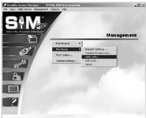
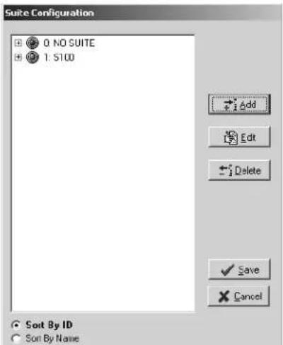
- At the Suite Configuration PC dialog box, highlight the suite and click Edit to change the suite information.
Note: Click Delete to remove the suite from the system.
Section 3: The Site Design Process
Editing Suite Information (continued)
- At the Suite Edit PC dialog box, you can change the name of the suite, assign the suite to a different zone, or make the suite inactive.
- Click OK when your changes are complete.
- Click Save to save your changes.


Section 3: The Site Design Process
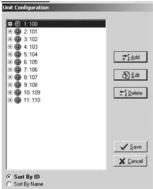
3.5 Entering Unit Lock Information
The next step is to input information for all your property's units or apartments into the SAM RF System. The SAM RF System allows you to add up to 4000 units.
- Click on the Management menu at the top of the window or the Management icon.
-
Point to Site Design, then select Unit Locks...
-
Click Add at the Unit Configuration PC dialog box.

Section 3: The Site Design Process
Entering Unit Lock Information (continued)
- Like the Suite Configuration PC dialog box, the Unit Configuration PC dialog box will be empty. To add units, click Add.

-
In the top field labeled Unit Name, type in the designation for the first unit (e.g., Unit 101, Building A, Unit 101, etc.) and click Add.
-
The unit you just named will appear in the list box below the Unit Name field. You can continue adding additional units in this manner, or you can add a range of units to the system, as long as they are all in the same zone and/or suite.
![Unit Add Unit Name: BUILDING A UNIT Add Add Name Range None Poets Postale 0 TO 0 Zone for Units 0: [NO ZONE] Suite For Units: 0: NO SUITE Remove OK Cancel](/content/2026/05/932090/images/a5e0a1e281225f5bee817d4b97eb86f8a6288f086e62b719bc6a128ada4b0dfb.jpg)
To add a range of units from the same zone into the system, type the word Unit or another appropriate name (e.g., Building A, Unit 101, etc.), in the Unit Name box, then go to the Add Name Range area.
To add the numeric information BEFORE the information entered into the Unit Name box, click the open circle in front of Prefix; to add the numeric information AFTER the information entered into the Unit Name box, click the open circle in front of Postfix. Now enter the range of unit numbers, such as 101 to 999, and click Add.
Note: If you are using numbers, be sure to use only two- or three-digit numbers by including a 0 in front of any single- or double-digit numbers. For example, use 01 or 001 (not 1), 02 or 002 (not 2), or 10 or 010 (if three digits are being used). This will ensure that the units are listed in the proper order later in the site design process.
Section 3: The Site Design Process
Entering Unit Lock Information (continued)
The units you just named will appear in the list box below the Unit Name field. If the information in the box is not listed as you had intended, you can delete the entries individually by clicking on an entry and clicking Remove. To delete all the entries at one time, click on the first entry, hold down the SHIFT key and click on the last entry to highlight everything in the box. Click Remove and start over.
Once you have created the appropriate list of units, go to the Zone for Units pull-down box to indicate in which zone this unit (or range of units) is located. Because you have already set up all the zones for your property, the appropriate zone (such as Building A) should already be in the pull-down box. Click on the zone name. It will then appear in the field directly under Zone for Units.

If the units are part of a suite, go to the Suite for Units pull-down box to indicate which suite these units are in. Because you have already set up all the suites for your property, the appropriate suite (such as Building 1, Suite A) should already be in the pull-down box. Click the suite for these units. It will then appear in the field under Suite for Units.

Section 3: The Site Design Process
Entering Unit Lock Information (continued)
Saving Unit Information
When you are satisfied that all information for this unit or range of units is accurate, click OK. Back at the Unit Configuration PC dialog box, the unit or range of units you just added will appear in boldface type. Continue adding individual units or range of units in the same manner as described above. All units added will appear in bold in the Unit Configuration PC dialog box until you save them in the SAM RF System.
When you have finished creating and designating the appropriate number of units for your property, click Save at the Unit Configuration PC dialog box to store the information in the SAM RF System. To confirm that all unit information has been saved, go back to the Unit Configuration PC dialog box. The unit names you just registered should no longer appear in boldface type.
Section 3: The Site Design Process
3.6 Editing Unit Lock Information
After the unit lock information has been entered, you can make changes at any time.
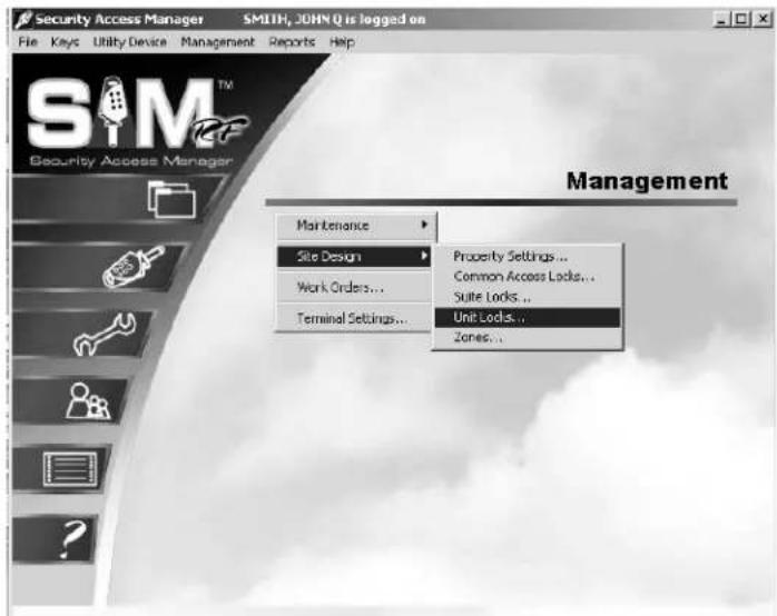
- Click on the Management menu at the top of the window or the Management icon.
-
Point to Site Design, then select Unit Locks...
-
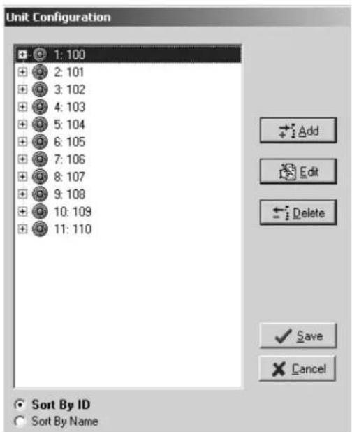
At the Unit Configuration PC dialog box, highlight the unit that you would like to edit and click Edit.

Section 3: The Site Design Process
Editing Unit Lock Information (continued)
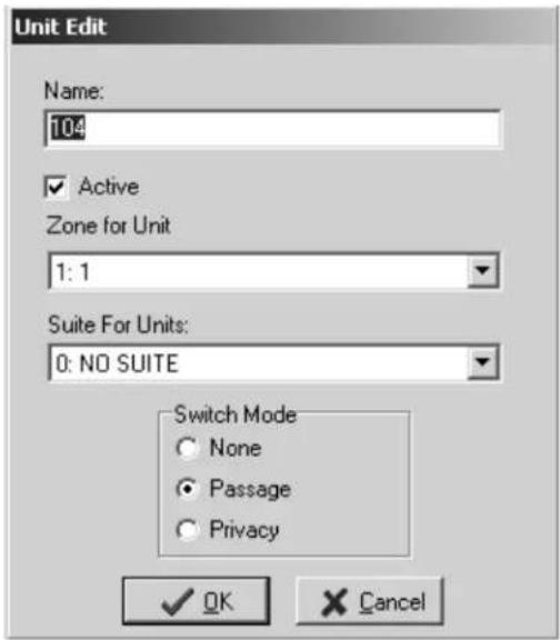
- At the Unit Edit PC dialog box, you can change the number or name of the unit, assign the unit to a different zone or suite, or make the suite inactive.
- Click OK when your changes are complete.
- Click Save to save your changes.
Section 3: The Site Design Process
3.7 Entering Common Access Area Information
Common access areas are areas with locks that need to allow access to a number of people (tenants, maintenance staff, etc.). Common access areas on your property may include community pools, garages, laundry rooms, and more. In addition, if you have buildings with doors that provide access to all the units within, the locks on those doors would be considered common access locks.
- Click on the Management menu at the top of the window or the Management icon.
- Point to Site Design, then select Common Access Locks...
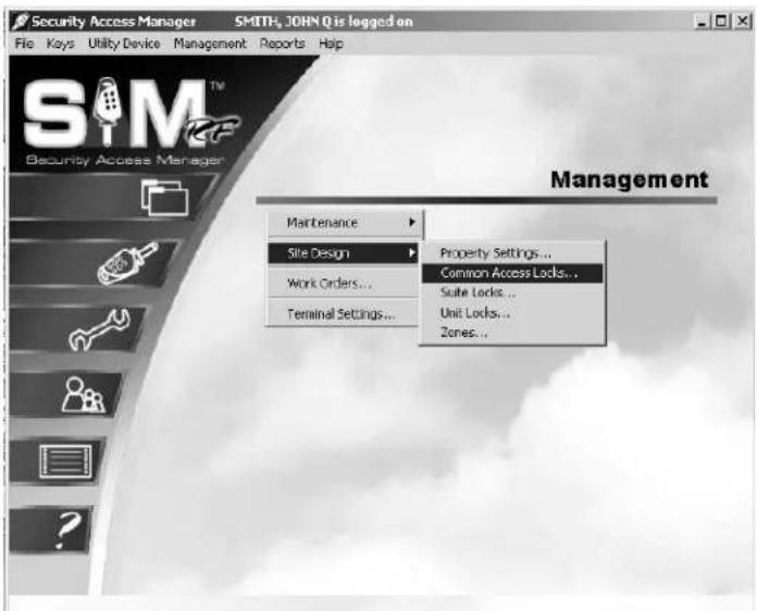
- At the Common Access Lock Configuration PC dialog box, you will immediately see a number of rows with the designation COMMON ACCESS LOCK with a number beside it starting with COMMON ACCESS LOCK 01 and going up to COMMON ACCESS LOCK 64. Each of these entries can be assigned a specific descriptive name to represent the various common access areas on your property.
![Common Access Lock Configuration 1: [COMMON ACCESS LOCK 01] 2: [COMMON ACCESS LOCK 02] 3: [COMMON ACCESS LOCK 03] 4: [COMMON ACCESS LOCK 04] 5: [COMMON ACCESS LOCK 05] 6: [COMMON ACCESS LOCK 06] 7: [COMMON ACCESS LOCK 07] 8: [COMMON ACCESS LOCK 08] 9: [COMMON ACCESS LOCK 09] 10: [COMMON ACCESS LOCK 10] 11: [COMMON ACCESS LOCK 11] 12: [COMMON ACCESS LOCK 12] 13: [COMMON ACCESS LOCK 13] 14: [COMMON ACCESS LOCK 14] 15: [COMMON ACCESS LOCK 15] 16: [COMMON ACCESS LOCK 16] 17: [COMMON ACCESS LOCK 17] 18: [COMMON ACCESS LOCK 18] 19: [COMMON ACCESS LOCK 19] Edit Save Cancel Sort By ID Sort By Name](/content/2026/05/932090/images/97ff845e001c1eada3d7ac5ad4e2d4749a513132e195c1693aa7ce8bdc13ab0a.jpg)
Section 3: The Site Design Process
Entering Common Access Area Information (continued)
- To begin entering common access information, click on 1: COMMON ACCESS LOCK 01 and then click Edit. This will display the Common Access Lock Edit PC dialog box.
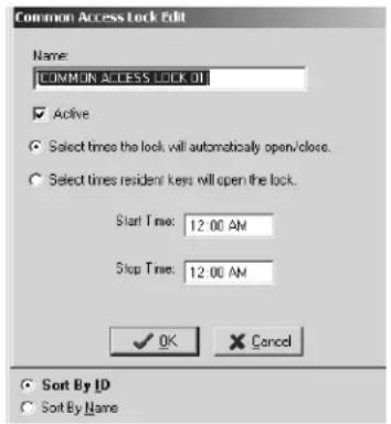
- In the Name field, highlight over COMMON ACCESS LOCK 01 and type in an appropriate name for this area, such as Building A Front Door, Building A Pool, or Laundry Room.
Note: If you are using numbers, be sure to use only two-digit numbers. For example, use Building 01 Pool (not Building 1 Pool), Building 02 Laundry Room (not Building 2 Laundry Room). This will ensure that the common access area names are listed in the proper order later in the site design process.
- By default, the Active field will be checked. The Select times the lock will automatically open/close field will be checked. Below this you will see the Start Time and Stop Time. If you want the lock to automatically open and close, type in the Start Time and Stop Time to give access to this lock. No key will be required during the hours you have selected to enter that area. Outside the time frame, resident keys will be inoperable.
- You also may choose another lock access option when you choose the Select times resident keys will open the lock field on this screen. When you check the box next to this field, the Start Time and Stop Time will be listed as 12:00 AM. This will allow the common access area to be accessible at any time of day to anyone with an appropriate key.
- To limit the number of hours an area is accessible, simply change the Start Time and Stop Time. For example, to limit entry to the pool between midnight and 6:00 AM, enter 6:00 AM for the Start Time and 12:00 AM for the Stop Time. During the inactive times, Resident keys will not work.
- When you are satisfied with the information, click OK. Back at the Common Access Lock Configuration PC dialog box, the common access area information you just entered will appear in bold. Continue designating common access areas in the same manner.
- When you have finished entering all the common access areas for your property, click Save at the Common Access Lock Configuration PC Dialog Box to store the information in the SAM RF System. To confirm that all common access area information has been saved, go back into the Common Access Lock Configuration PC dialog box. The names of the common access areas you just registered should no longer appear in boldface type.
Note: If your property adds additional common area locks in the future without defaulting to ON, existing Resident keys will not work in the new lock.
Section 3: The Site Design Process
3.8 Confirming Property Settings
The next step in the site design process is to confirm or reconfigure your property settings within the SAM RF System. These settings include the default common access options for the unit and zone keys that you just set up, the automatic adjustor for Daylight Saving Time, and the name and identification numbers for your property.
- Click on the Management menu at the top of the window or the Management icon.
- Point to Site Design, then select Property Settings...

- Click on the General tab at the top of the box. The name of your property should already be listed in the Property Name field. The factory will also have filled in the Distributor Code and Customer Code fields. This information helps to distinguish one property from another so that keys made for your property will not open locks at any other property and vice versa.
- Confirm that your property's Name is correct. You can also confirm that the Distributor Code and the Customer Code are correct by matching them to your invoice, but this is not absolutely necessary.

Section 3: The Site Design Process
Confirming Property Settings (continued)
Unit Keys
To continue on to the next section, simply click on the Unit Keys tab at the top of the box. You will immediately see the common access area options you just set up listed in alphanumeric order. By default, all common access area options should already be checked.
You can accept the default settings as they are or check/uncheck different options. For example, you may have set up storage rooms in each zone as common access areas, but you will only allow tenants to have access to the storage rooms in their own buildings. In this case, you will want to uncheck the storage rooms for now, and recheck them later when you make unit keys for each particular building or zone.
![Property Settings General Limit Keys Zone Keys DST Audit Default common access lock information for resident/unit keys LAUNDRY ROOM PARKING GARAGE POOL [COMMON ACCESS LOCK 04] [COMMON ACCESS LOCK 05] [COMMON ACCESS LOCK 06] [COMMON ACCESS LOCK 07] [COMMON ACCESS LOCK 08] [COMMON ACCESS LOCK 09] [COMMON ACCESS LOCK 10] [COMMON ACCESS LOCK 11] [COMMON ACCESS LOCK 12] [COMMON ACCESS LOCK 13] OK Cancel Mark All Clear All](/content/2026/05/932090/images/62bde4c1ec265fcac9e6efefa6fbbe3b0181d0bce450d89165142c1d5e939e03.jpg)
When you are satisfied with the default or corrected common access options for Unit Keys, click OK to save the settings. This will take you back to the SAM RF System main menu screen.
Zone Keys
To confirm the common access options for zone keys, go back to the Management pull-down menu and select Property Settings.

Click on the Zone Keys tab at the top of the box. Just as with the Unit Keys tab, you will immediately see the common access options that have already been set up in the SAM RF System.
Once again, you can accept the default settings or check/uncheck different options. When you are satisfied with the default or corrected common access options for Zone Keys, click OK to save the settings.
![Property Settings General Unit Keys Zone Keys DST Audit Default common access lock information for zone keys LAUNDRY ROOM PARKING GARAGE POOL [COMMON ACCESS LOCK 04] [COMMON ACCESS LOCK 05] [COMMON ACCESS LOCK 06] [COMMON ACCESS LOCK 07] [COMMON ACCESS LOCK 08] [COMMON ACCESS LOCK 09] [COMMON ACCESS LOCK 10] [COMMON ACCESS LOCK 11] [COMMON ACCESS LOCK 12] [COMMON ACCESS LOCK 13] Mark All Clear All OK Cancel](/content/2026/05/932090/images/8a9115a7a924b7f28603e08db539932ca60512f4eb645bd4039ce1d2796c99e7.jpg)
Section 3: The Site Design Process
Confirming Property Settings (continued)
DST
For most of the U.S., Daylight Saving Time (DST) runs from the second weekend in March to the first weekend in November (starting in 2007). Although the SAM RF System assigns access time to each key produced, with the default being 24 hours per day, some keys, such as Limited Use keys, have specific expiration times, either by default or by configuration. If the region in which you live does NOT change the clocks for DST (these areas presently include Alaska, Hawaii, Arizona and parts of Indiana), you will need to configure SAM RF to take that into account so that the assignment of expiration times are accurate.
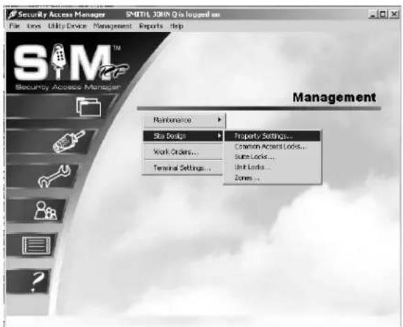
- To confirm that the SAM RF System will account for DST properly for your region of the country, click on the Management menu at the top of the window or the Management icon.
-
Point to Site Design, then select Property Settings...
-
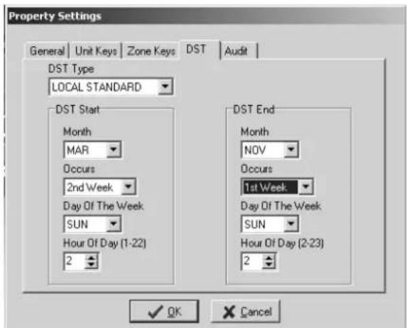
Click on the DST tab at the top of the box.
-
To set your DST to the current standard, change your DST Type to LOCAL STANDARD.
-
For DST Start, change Month to MAR and Occurs to 2nd Week.
- For DST End, change Month to NOV and Occurs to 1st Week.
Note: If your area does not observe DST, you may alternately choose NONE or NON-STANDARD in the box under DST Type and choose the appropriate options.
- When you have chosen a setting, click OK.
Section 3: The Site Design Process
Confirming Property Settings (continued)
Audit
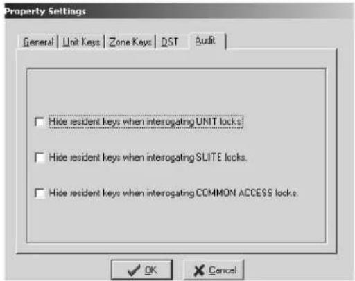
You will now need to determine if you wish to view or hide within your lock audit reports the use of Resident keys in your unit, suite, and common access locks.
- To select the viewing option for each lock type within your site design, click on the Management menu at the top of the window or the Management icon.
- Point to Site Design, then select Property Settings...

- Click on the Audit tab at the top of the box. You will see the message for the three different lock options, "Hide resident keys when interrogating," and the name of the lock.
- Click on the square box next to message of the respective locks you have determined you don't want to show resident key use in the audit trail. Do not click the boxes of those lock options where you do wish to see the resident key use in the audit trail.
- After making your selections, click OK.
SAM® RF
Operations Manual
Section 4:
Management
All information contained herein, including but not limited to product pricing and other intellectual property, is confidential and intended for the sole use of the addressee(s) so named. Any misuse of this confidential information contained herein may result in legal action by Computerized Security Systems dba SAFLOK and its parent company.
Section 4: Management Functions
4.1 Assigning the System Administrator
If you are the system administrator, you must register yourself in the SAM RF System and assign yourself the authority of the system administrator.
-
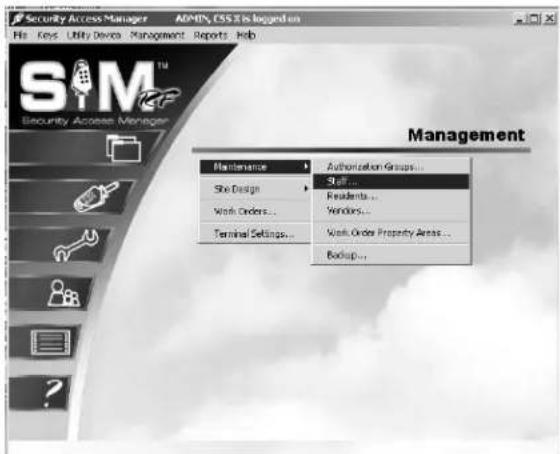
To register yourself as the system administrator in the SAM RF System, click on the Management menu at the top of the window or the Management icon.
-
Point to Maintenance, then select Staff...
-
At the Staff List PC dialog box, the default user will appear on the screen. Click Add on the right-hand side of the screen to create your system administrator identity and authorization.

Section 4: Management Functions
Assigning the System Administrator (continued)
- Using the example to the right as a guide, type your information into the Staff Form – ADD Mode PC dialog box. At the top, type in your last name, first name, and middle name or initial (optional) in the appropriate fields. In the Position field, type Administrator, Manager, or another appropriate descriptor.
Note: A user name can range from one to 15 characters and a password can range from three to ten characters. This information will become the user ID and password that you will use each time you log on to the SAM RF System.
- Click on the small box next to Administrator. This will give you full authority to access all aspects of the SAM RF System.

- Click Save. You will return to the Staff List PC dialog box. Click Close to return the SAM RF System main menu.
Note: If someone else will ultimately be the system administrator, you can register him/her using these instructions. You may still want to register yourself with full system administrator authority if you will be performing a number of administrative functions.
Section 4: Management Functions
4.2 Removing the Default System Administrator
Once you have registered yourself (and/or someone else) as the system administrator, it is highly recommended that you remove the default system administrator (ADMIN, CSS) from the SAM RF System.
- Log off the system (File, Log Off) and then log on again using your new user name and password.
- Click on the Management menu at the top of the window or the Management icon.
- Point to Maintenance, then select Staff...
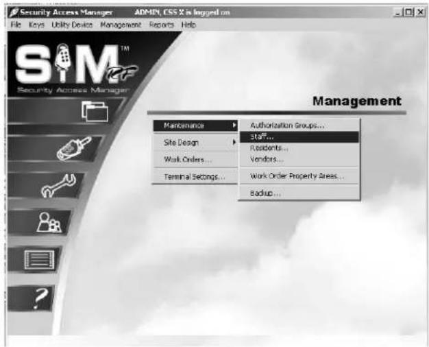
- Within the Staff List PC dialog box, click on ADMIN, CSS to highlight it, and then click Delete.
- A Delete Confirmation PC dialog box will appear, asking, "Do you wish to delete ADMIN, CSS?" Click Yes to confirm the deletion.
- Back at the Staff List PC dialog box, you can click Close to return to the SAM RF System main menu screen, or stay in the Staff List PC dialog box to register SAM RF System users.

Section 4: Management Functions
4.3 Creating Authorization Groups
Assigning a staff member to a specific authorization group allows that person access to a specific (and limited) list of SAM RF System functions, such as assigning work orders or creating new keys, rather than allowing access to the entire system.
Be very careful as you determine how much access to give to other users of the system.
- Click on the Management menu at the top of the window or the Management icon.
- Point to Maintenance, then select Authorization Groups...
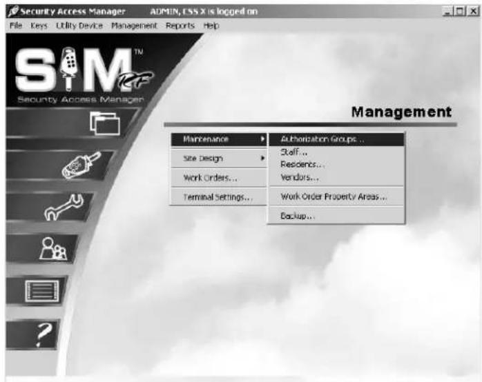
- At the Authorization Groups PC dialog box, there will be no authorization groups listed in the box. To create new authorization groups, click Add on the right hand side of the PC dialog box to display the Authorization Group – ADD Mode PC dialog box.

Section 4: Management Functions
Creating Authorization Groups (continued)
- Create and type a name for it in the Name field at the top of the PC dialog box. It is recommended that the name be something that is easily identifiable, such as Maintenance or Work Order Access. We've added a Unit Access authorization group as an example.
- Below the Name field are two tabs – System Authorizations and Key Authorizations – each with a list of options from which to choose. A list of System Authorization options with short definitions follows. To select options, simply click in the small box next to the option so a check mark appears in it.

System Authorizations
Read Key – Allows the user to use the electronic key encoder to read a key
Rename Unit – Allows the user to go into the site design section and change the names of units
Change Active State of Unit – Allows the user to go into the site design section and edit the active state of a unit
Add Unit – Allows the user to go into the site design section and add additional units to the system.
Move Unit From Zone – Allows the user to go into the site design section and change a unit's zone assignment
Move Unit From Suite – Allows the user to go into the site design section and change a unit's suite assignment
Change Switch Mode of Unit – Allows the user to go into the site design section and change a unit's switch mode. Not applicable at this time
Rename Common Access Lock – Allows the user to go into the site design section and change the names of common access locks
Change Active State of Common Access – Allows the user to go into the site design section and edit the active state of a common access lock
Change Start/Stop Time of Common Access – Allows the user to edit the start and stop times of a common access lock
Change Auto Open of Common Access – Allows the user to change the time a common access lock will automatically open
Section 4: Management Functions
Creating Authorization Groups (continued)
Rename Zone – Allows the user to go into the site design section and rename a zone
Change Active State of Zone – Allows the user to go into the site design section and edit the active state of a zone
Edit Vendor Company – Allows the user to go into the maintenance section and edit information about a vendor company
Delete Vendor Company – Allows the user to go into the maintenance section and delete a vendor company from the SAM RF System
Add Vendor Company – Allows the user to go into the maintenance section and add a vendor company to the SAM RF System
Edit Vendor Employee – Allows the user to go into the maintenance section and edit information about a vendor employee
Delete Vendor Employee – Allows the user to go into the maintenance section and delete a vendor employee from the SAM RF System
Add Vendor Employee – Allows the user to go into the maintenance section and add a vendor employee to the SAM RF System
Edit Resident – Allows the user to go into the maintenance section and edit information about a resident
Delete Resident – Allows the user to go into the maintenance section and delete a resident from the SAM RF System
Add Resident – Allows the user to go into the maintenance section and add a resident to the SAM RF System
Edit Staff – Allows the user to go into the maintenance section and edit information about a staff member
Delete Staff – Allows the user to go into the maintenance section and delete a staff member from the SAM RF System
Add Staff – Allows the user to go into the maintenance section and add a staff member to the SAM RF System
Utility Device Update Clock – Allows the user to reset the date and time in a lock(s)
Utility Device Update Common Access – Allows the user to edit information in common access lock(s)
Utility Device Download Audit – Allows the user to prepare the utility device to go to the lock to retrieve its audit trail information
Utility Device Get Lock Info – Allows the user to prepare the utility device to retrieve information from a lock(s) about its identity, current date and time and current battery voltage information
Utility Device Read Lock Info – Allows the user to display or print information that has been retrieved after getting lock info (see above)
Section 4: Management Functions
Creating Authorization Groups (continued)
Utility Device Upload Audit – Allows the user to upload lock audit trail information from the utility device into the PC for display or printing
Utility Device Battery Backup – Allows the user to access a lock with a dead battery
Edit Property Settings – Allows the user to go into the site design section and edit information regarding default settings and more
Edit Work Order – Allows the user to go into the work order section and edit a work order
Delete Work Order – Allows the user to go into the work order section and delete a work order
Add Work Order – Allows the user to go into the work order section and add a work order
Rename Suite – Allows the user to go into the site design section and change the names of suites
Change Active State of Suite – Allows the user to go into the site design section and edit the active state of a suite lock
Add Suite – Allows the user to go into the site design section and add additional suites to the system
Move Suite From Zone – Allows the user to go into the site design section and change a suite's zone assignment in the SAM RF System
Change Switch Mode of Suite – Allows the user to go into the site design section and change a suite's switch mode. Not applicable at this time
Edit Area – Allows the user to go into the Work Order Property Areas and edit information about locations in the SAM RF System
Delete Area – Allows the user to go into the Work Order Property Areas to delete locations from the SAM RF System
Add Area – Allows the user to go into the Work Order Property Areas and add additional locations to the SAM RF System
View Reports – Allows the user to view reports on the PC
Program Unit Locks – Allows the user to use the utility device to program unit locks
Program Common Access Locks - Allows the user to use the utility device to program common access locks
Program Suite Locks - Allows the user to use the utility device to program suite locks
Section 4: Management Functions
Creating Authorization Groups (continued)
- Under the Key Authorizations tab, every key that can be created is listed under Key Types and the transactions that can be performed are listed under Authorizations.
To select any or all of these options, click on the name of the specific key type in the left-hand column and then click in the small box next to the authorization so a check mark appears in it in the right-hand column. Repeat for each key type.
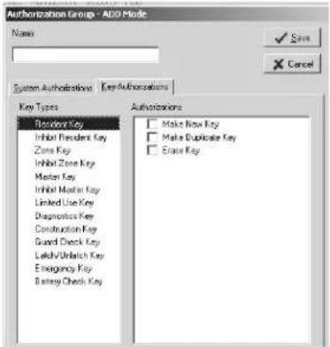
Key Types
Resident Key – A Resident key will be issued to the resident. This key will allow them to gain access into their individual unit, as well as any associated suite and common access locks.
Inhibit Resident Key – An Inhibit Resident key is used to cancel a resident key out of locks if a key was lost or stolen.
Zone Key – Zone keys will open specific groups of unit locks, including all the units in a building or all the units on a floor, as designated in the site design process. A Zone key will be issued to employees who need access to those units.
Inhibit Zone Key – An Inhibit Zone key is used to cancel a Zone key out of locks if a key was lost or stolen.
Master Key – A Master key will open every lock on the property. These keys should be issued to employees that need access to all units, suites and common access areas.
Inhibit Master Key – An Inhibit Master key is used to cancel a Master key out of locks if a key was lost or stolen.
Limited Use Key – A Limited Use key is issue to vendors who need access to specified unit lock(s). It will work for a limited period of time on a specified date.
Diagnostics Key - The Diagnostics key is designed to help analyze and reveal why a key will not gain entry.
Construction Key – Construction keys allow you and you staff to gain access into locks that have just been installed and have not yet been programmed using the utility device.
Guard Check Key – The Guard Check key allows your staff or security to register their patrol throughout your property at common access locks.
Latch/Unlatch Keys - The Latch/Unlatch key allows a common access lock to be unlatched and latched.
Section 4: Management Functions
Creating Authorization Groups (continued)
Emergency Key – An Emergency key will open every lock on the property including units, suites and common access areas. These keys should be held by the property management and be available for the fire department.
Battery Check Key - The Battery Check key is a non-opening key that is designed to check the battery voltage in the lock
For each Key Type, you can authorize users to perform three tasks:
- Make New Key
- Make Duplicate Key
- Erase Key
Note: If one of these three options appears dark, that option is not available for that particular key.
- When you have finished assigning system authorizations and key authorizations, click Save at the Authorization Group-Add Mode PC Dialog Box. Once you have setup your authorization groups, your next task is to add system users.
Section 4: Management Functions
4.4 Adding SAM RF System Users
System users are loosely defined as the people who will be using the SAM RF System. However, it is recommended that you register all staff members, whether they will be directly using the SAM RF System or not. This will make performing such functions as creating staff keys or assigning work orders an easier process. You can register system users now or at any time in the future.
-
Click on the Management menu at the top of the window or the Management icon.
-
Point to Maintenance, then select Staff...

- Within the Staff List PC dialog box, click Add to display the Staff Form – ADD Mode PC dialog box.

Section 4: Management Functions
Adding SAM RF System Users (continued)
- Enter the person's name. At the top of the form are fields for inputting each person's last, first and middle name/initial (optional).
- Enter information about his/her position. In the Position field, type in a word or two that identifies this person's position or responsibility at your site, such as Manager or Maintenance.
- Enter the System Authorization Information. Create a user name and password for this person.

Note: A user name cannot be more than 15 characters and a password cannot be more than 10 characters. Keep in mind that this information will become the user ID and password that each user will type in when logging on to the SAM RF System. Be sure it is something they can easily remember. For this reason, it is recommended that you employ an easily identifiable system for assigning user names, such as the person's first initial and last name. For example, Jane Doe's user name would be JDOE.
As the system administrator, you will have access to user name and password information in the future. This will be useful in cases where you need to add or remove users from the system or change passwords.
- Assign the authority level. It is highly recommended that you not give administrator privileges to any other users of the SAM RF System. In other words, leave the Administrator box unchecked. Below the Administrator box is a larger box that should now contain the names of authorization groups that you have set up.
- To assign the authorization group, click in the box next to the group name so that a check mark appears in the box.
Note: Authorization groups were created in the previous section as a shortcut for assigning authorizations to system users.
- Click Save to return to the Staff List PC dialog box. Click Add to add the next user and follow the process once again. When you have registered all staff members in the SAM RF System, click Close to return to the SAM RF System main menu screen.
Section 4: Management Functions
4.5 Adding New Staff to the SAM RF System
You can register additional system users now or any time in the future, such as when a new staff member joins your team.
-
Click on the Management menu at the top of the window or the Management icon.
-
Point to Maintenance, then select Staff...
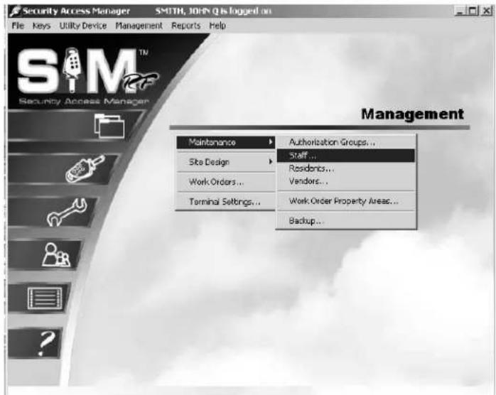
- At the Staff List PC dialog box, click Add to display the Staff Form – ADD Mode PC dialog box.

Section 4: Management Functions
Adding New Staff to the SAM RF System (continued)
4. Complete the Staff Form.
Enter the person's name. At the top of the form are fields for inputting each person's last, first and middle name/initial (optional).
Enter information about his/her position. In the Position field, type in a word or two that identifies this person's position or responsibility at your site, such as Manager or Maintenance.
Enter the System Authorization Information. Create a user name and password for this person.

Note: A user name cannot be more than 15 characters and a password cannot be more than 10 characters. Keep in mind that this information will become the user ID and password that each user will type in when logging on to the SAM RF System. Be sure it is something they can easily remember. For this reason, it is recommended that you employ an easily identifiable system for assigning user names, such as the person's first initial and last name. For example, John Smith's user name would be "jsmith."
As the system administrator, you will have access to user name and password information in the future. This will be useful in cases where you need to add or remove users from the system or change passwords.
Assign the authority level. It is highly recommended that you not give administrator privileges to any other users of the SAM RF System. In other words, leave the Administrator box unchecked.
Below the Administrator box is a larger box that contains the names of authorization groups that you have set up. An authorization group is essentially a label that represents access to a specific (and limited) list of SAM RF System functions – such as assigning work orders or creating new keys – rather than allowing access to the entire system.
Once you have set up authorization groups in the SAM RF System, you can go back and edit the authority level of certain staff members by selecting one of the authorization groups that will then appear in the System Authorization Information box. See Section 4.3 "Creating Authorization Groups."
- Click Save to return to the Staff List PC dialog box. Click Add to add the next user and follow the process once again. When you have registered all staff members in the SAM RF System, click Close to return to the SAM RF System main menu screen.
Section 4: Management Functions
4.6 Preventing Staff Access
When staff members leave your employment, it is highly recommended that you delete them from the SAM RF System and change any existing passwords for current staff. This will prevent previous employees from accessing the information contained in the system or possibly creating new keys.
-
Click on the Management menu at the top of the window or the Management icon.
-
Point to Maintenance, then select Staff...
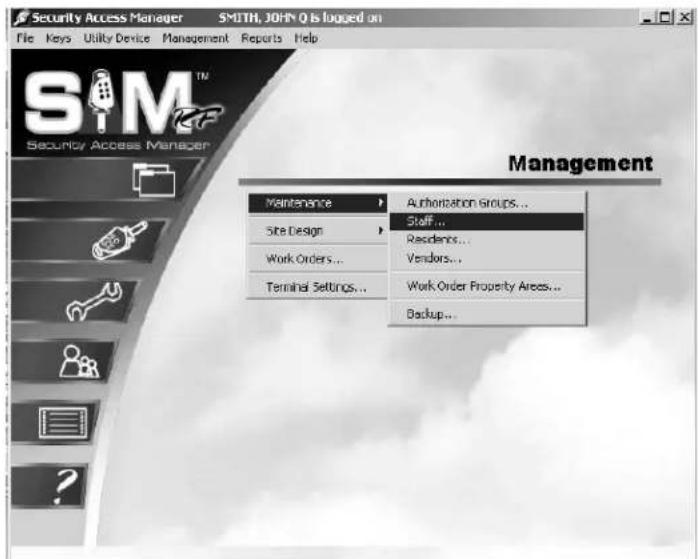
-
Within the Staff List PC dialog box, click on the person's name you wish to delete, and click Delete.
-
A Delete Confirmation box will appear, asking if you are sure about deleting that person.
-
Click Yes to confirm deletion and then click Close at the Staff List PC dialog box to return to the SAM RF System main menu screen.
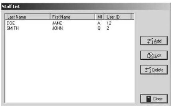
IMPORTANT: In the event that an employee does not return his or her key, see the Creating Inhibit Keys section to inhibit staff access. If former staff members do not relinquish their keys, they can continue to gain access to common access areas or to your residents' units. Merely deleting staff members from the SAM RF System is not enough to ensure the security of your property. It is also very important that you collect whatever keys they might have in their possession.
To ensure the security of your property whether or not you have collected any keys in former staff members' possession, you should reprogram the locks where these staff members previously had access. To reprogram these locks, you need an Inhibit key.
An Inhibit key is programmed to tell a lock to ignore keys with specific key IDs. If you assign key IDs carefully in the key creation process, the inhibiting process will be simple.
Section 4: Management Functions
4.7 Adding Residents to the SAM RF System
- Click on the Management menu at the top of the window or the Management icon.
-
Point to Maintenance, then select Residents...
-
At the Unit/Resident List PC dialog box, all units within your property will appear in the Unit/Resident List. Click on the unit where the resident is moving, then click Add.
-
At the Resident Form – ADD Mode PC dialog box, enter as much information as you can about the resident, including his or her name, work phone and home phone numbers. There is also space to record some notes about the resident.


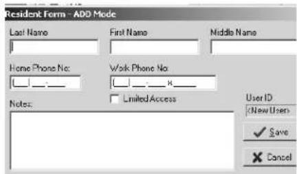
Note: If the Limited Access box is checked here at this Add Mode screen, when making keys for this resident, any defaults for common access areas previously set will be disabled. An example of when to check the limited access box would be for children residing in the unit who may not have access to the pool or health club. You can still manually select common access areas you may want the resident to have access to when making the key.
Section 4: Management Functions
Adding Residents to the SAM RF System (continued)
- When you have entered as much information as you wish about the resident, click Save. This will return you to the Unit/Resident List PC dialog box.
- If more than one resident will be moving into the same unit, click on that specific unit once again at the Unit/Resident List PC dialog box and enter information about the next person moving in. Continue registering additional residents moving into that same unit – or into a different unit – following the same process. Click Close at the Unit/Resident List PC dialog box to return to the SAM RF System main menu screen.
Section 4: Management Functions
4.8 Deleting Residents
When residents move out of your property, it is highly recommended that you delete them from the SAM RF System.
- Click on the Management menu at the top of the window or the Management icon.
-
Point to Maintenance, then select Residents...
-
At the Unit/Resident List PC Dialog Box, click the Plus Sign (+) next to the unit number in which the resident resides.
-
Click on the person's name you wish to delete, and then click Delete.

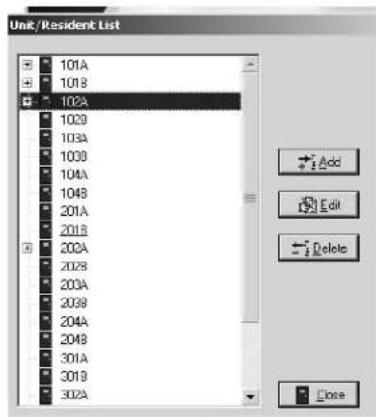

Section 4: Management Functions
Deleting Residents (continued)
- A Delete Confirmation PC dialog box will appear asking if you are sure about deleting that person. Click Yes to confirm, and then click Close at the Unit/Resident List PC dialog box to return to the SAM RF System main menu screen.
- Repeat the process until all residents vacating a unit are removed from the SAM RF System.
- Merely deleting residents from the SAM RF System is not enough to ensure the security of your property. If former residents do not relinquish their keys, they can continue to gain access to common access areas and to their former unit(s). It is also very important that you collect whatever keys former residents might have in their possession.
To ensure the security of your property AND the security of the new residents of that unit, it is important to make sure that any keys in a former resident's possession will no longer provide access.
To prevent access, you must reprogram the locks that the residents previously had access to. To reprogram these locks, you need to create an Inhibit Resident key. If a new resident will be moving in immediately you do not need to create an Inhibit Resident key. When the new resident key is made and used in the lock(s) it will invalidate the previous resident(s) keys.
Note: If you have new residents to register, follow the process "Adding Residents to the SAM RF System" described earlier in this section.
Section 4: Management Functions
4.9 Adding Vendors to the SAM RF System
- Click on the Management menu at the top of the window or the Management icon.
- Point to Maintenance, then select Vendors...

- Click Add at the Vendor Company List PC dialog box.
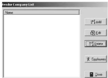
- Input as much information as you wish about the vendor company in the fields provided including:
• The vendor's company name
- The vendor type, such as Plumber, Painter, etc.
- Address and phone number information
- Click Save to return to the Vendor Company List PC dialog box. If you would like to add another vendor to the system right away, click New and follow the process once again.

Section 4: Management Functions
Adding Vendors to the SAM RF System (continued)
-
To register employees of a specific vendor company, be sure you are in the Vendor Company List PC dialog box. Click on the vendor for which you will be registering employees and click Employees. This will display the Vendor Employee List PC dialog box.
-
To register a new vendor employee, click Add. This will display the Vendor Employee Form – ADD Mode PC dialog box.
-
Enter as much information as you can about the employee, including his or her name, position and the phone number that he or she uses most often. When you have entered as much information as you wish, click Save. This will return you once again to the Vendor Employee List PC dialog box.
-
Continue registering additional vendor employees by following the same process, or click Close at the Vendor Employee List PC dialog box and again at the Vendor Company List PC dialog box.
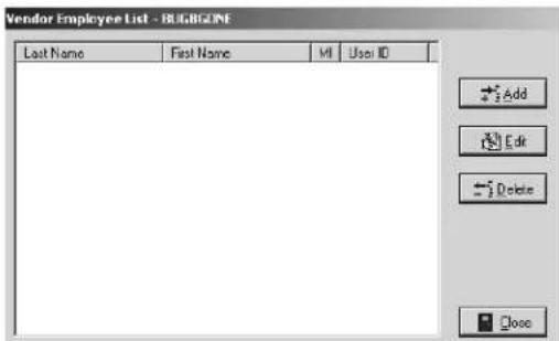

Section 4: Management Functions
4.10 Creating and Viewing Work Orders
Not only does the SAM RF System provide enhanced security for your property, it also enhances the level of service you can provide to your residents, specifically through the use of computer-generated work orders for property maintenance.
The SAM RF System allows you to create new work orders, assign them to specific staff members or vendors, and track and edit them as they are processed. Pending and open work orders are interrelated with limited use keys. They are easily identified as they appear in bold print when making limited use keys.
-
To view existing work orders, click on the Management menu at the top of the window or the Management icon.
-
Click on Work Orders.

-
The Work Order List PC dialog box provides a number of viewing options for existing work orders. For instance, under Work Order Type, you can choose the Unit option to view all work orders for all units or just for a single unit. Alternatively, you can choose the Property option, which will list any work orders for common access areas around your property.
-
Next, you can choose to review only pending, open or closed work orders – or any combination of the three. You can also choose to review work orders based on the staff member to whom they were assigned by selecting a specific user.
![Work Order List Work Order Type Unit Property Fending Open Closed Show Users [ALL UNITS] [ALL USERS] Work Order Unit/Property Status Assigned To 20050825-1 U-101A PENDING V-TYSON, JIM 20050825-2 U-302A PENDING V-JONES, DAVE Add Edit Delete Export Close](/content/2026/05/932090/images/2d05f20f767cfe48e767d1dd1bc312668bc86e85f58de1e0467c499275f9534c.jpg)
Note: Whenever you make changes to the viewing options, it is important to click the Refresh button at the top right corner of the PC dialog box to update the screen.
Section 4: Management Functions
Creating and Viewing Work Orders (continued)
- To create a new work order, click Add to display the Work Order – ADD Mode PC dialog box.
The SAM RF System automatically assigns a work order number for later identification. In addition, the Date/Time Requested fields will automatically fill in with the current date and time.
- The first step in creating a new work order is to select the Work Order Type by clicking the small circle next to either Unit or Property. If the work order is for a unit, you will then select the unit number using the pull-down box below Unit. Property refers to other areas within the property in need of maintenance attention such as the pool or health club. If property is
selected, you will then select the area by using the pull down box below Property.
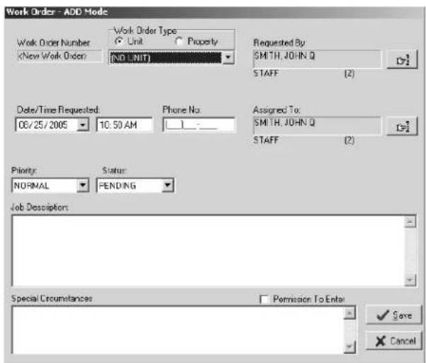
- A staff member or a resident can make service requests. By default, the name of the person currently logged on to the SAM RF System will appear in the box "Requested By." To change this information, click the button to the right of the box. (This button has a hand pointing to the right.) This will display the Select User Type PC dialog box.
If a resident requested the service, click the open circle next to Resident and click OK. This will take you to the Resident List PC dialog box.
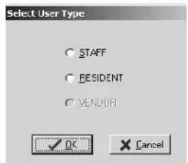
- Any residents registered into the system for that particular unit will be listed in this box. Click on the name of the person who reported the problem. Click Select.
Note: If the resident who requested the service is not in the resident list, see Section 4.7 "Adding Residents to the SAM RF System".
- If a staff member requested the service, click the open circle next to Staff and click OK.
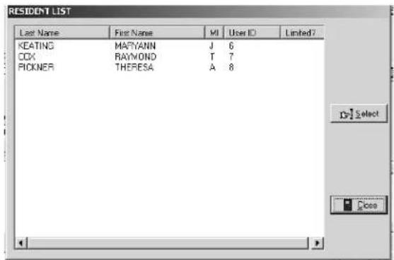
- At the Staff List PC dialog box, click on the name of the staff member who reported the problem and click Select. Back at the Work Order List PC dialog box, the name of the person you selected will appear in the box under the words, "Requested By."
Note: If the staff member who requested the service is not in the staff list, see Section 4.5 "Adding New Staff to the SAM RF System".
Section 4: Management Functions
Creating and Viewing Work Orders (continued)
- Work orders can be assigned to either a staff member or a vendor. By default, the name of the person currently logged on to the SAM RF System will appear in the box under the words, "Assigned To." To assign the work order to someone else, click the button to the right of the box. (This button has a hand pointing to the right.) This will display the Select User Type PC dialog box.

- Determine whether the work order will be assigned to a staff member or a vendor.
- If the work order is being assigned to a staff member, click the open circle next to Staff and click OK. This will take you to the Staff List PC dialog box. Click on the name of the staff member who will be assigned the work order and click Select.
- If the work order is being assigned to a vendor, click the open circle next to Vendor and click OK. This will take you to the Vendor Company List PC dialog box. Any vendors you previously registered into the system will be listed in this box. Click on the name of the vendor to whom you wish to assign this work order and click Select.
- If you would like to assign this work order to a specific vendor employee, click on the name of the vendor and then click Employees. This will display the Vendor Employee List PC dialog box.
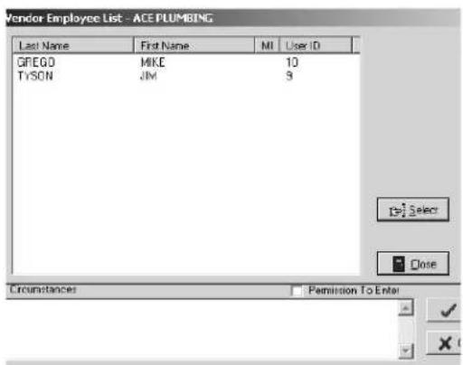
Note: If the vendor company or vendor employee you wish to assign the work order to is not in the vendor company list, see Section 4.9 "Adding Vendors to the SAM RF System".
-
Back at the Work Order – ADD Mode PC dialog box, the name of the person or vendor company you selected will appear in the box under the words, "Assigned To." If known, type that person's phone number into the Phone No. field.
-
If you wish to assign a date to this work order other than the current date/time, you can do so in this PC dialog box.
-
The next task is to select the Priority for this work order – Low, Normal or High – with Normal being the default. And because this is a new work order, you can accept the default Status of the work order as Pending.

Section 4: Management Functions
Creating and Viewing Work Orders (continued)
- The Work Order – ADD Mode PC dialog box has additional fields for recording a full description of the service problem as well as any additional information, such as whether or not permission to enter has been granted, if there is a pet on the premises, etc.
- When you are satisfied with all the settings for this work order, click Save.
- The Success PC dialog box will appear and show you the newly assigned work order number. Click OK.

Section 4: Management Functions
4.11 Editing Existing Work Orders
To keep accurate records, it may be necessary to make changes to existing work orders. For instance, if a work order is being reassigned to a different staff member or to a vendor, or when a work order's status goes from open to closed, that information should be recorded.
- To edit an existing work order, click on the Management menu at the top of the window or the Management icon.
- Click on Work Orders...

- At the Work Order List PC dialog box, click on the work order you wish to update and then click Edit. This will display the Work Order – Edit Mode PC dialog box.

Section 4: Management Functions
Editing Existing Work Orders (continued)
- Either a staff member or a resident can make service requests. To change this information, click the button to the right of the box. (This button has a hand pointing to the right.) This will display the Select User Type PC dialog box.
To change this information to a resident, click the open circle next to Resident and click OK. This will take you to the Resident List PC dialog box. Any residents you registered into the system for that particular unit will be listed in this box. Click on the name of the person who reported the problem and click Select.
Note: If the resident who reported the problem is not in the resident list, see Section 4.7 "Adding Residents to the SAM RF System" for instructions on adding that person to the list.
To change this information to a staff member, click the open circle next to Staff and click OK. This will take you to the Staff List PC dialog box. Click on the name of the staff member who requested the service and click Select.
Note: If the staff member who requested the service is not in the staff list, go to Section 4.5 "Adding New Staff to the SAM RF System" for instructions on adding that person to the list.
Back at the Work Order List PC dialog box, the name of the person you selected will appear in the box under the words, "Requested By."
- Work orders can be reassigned to either a staff member or a vendor. To change the work order assignment, click the button to the right of the box under the words, "Assigned To." (This button has a hand pointing to the right.) This will display the Select User Type PC dialog box.
6.
- If the work order is being reassigned to a staff member, click the open circle next to Staff and click OK. This will take you to the Staff List PC dialog box. Click on the name of the staff member who reported the problem and click Select.
- If the work order is being reassigned to a vendor, click the open circle next to Vendor and click OK. This will take you to the Vendor Company List PC dialog box. Any vendors you previously registered into the system will be listed in this box. Click on the name of the vendor you wish to assign this work order to and click Select.
- If you would like to assign this work order to a specific vendor employee, click on the name of the vendor company and then click Employees. This will display the Vendor Employee List PC dialog box.
Note: If the vendor to whom you wish to assign the work order is not in the vendor company list, go to Section 4.9 "Adding Vendors to the SAM RF System" for instructions on adding that vendor to the list.
- Back at the Work Order – Edit Mode PC dialog box the name of the person or vendor company you selected will appear in the box under the words, "Assigned To." If known, type that person's phone number into the Phone No. field.
- If you wish to assign this work order a new date/time, you can do so in this dialog box.
Section 4: Management Functions
Editing Existing Work Orders (continued)
- Other changes that can be made in the Work Order – Edit Mode PC dialog box are: changing the Priority (Low, Normal or High), its Status (Pending, Open or Closed) and adding more information to the Job Description and Special Circumstances fields.
- When you are satisfied with all the changes to this work order, click Save.
Although you have created and assigned a work order using the SAM RF System, it does not necessarily mean the person to whom the work order is assigned is aware of it. Somehow, that person needs to be informed that the work order exists and action needs to be taken.
There are essentially two ways to do this: (1) Print the work order out and hand it to the staff member it is assigned to (call/fax it to the vendor); (2) Provide access to the SAM RF System work orders functions for responsible staff members to retrieve and edit work orders themselves.
Section 4: Management Functions
4.12 Printing Work Orders
-
To print an existing work order, click on the Management menu at the top of the window or the Management icon.
-
Click on Work Orders...

- At the Work Orders List PC dialog box, click on the work order you wish to print and then click Report. This will display the Output Options PC dialog box.
- At the top of the Output Options PC dialog box, your default printer will be listed. Below that will be a Report Destination box along with three options:
• Printer: To print the report out as hard copy
- Preview: To view the report on screen
• File: To save the report to your hard drive or to disk.

Note: Although you have the option to print or to save the report to file, it is highly recommended that you first preview the report on screen. You will once again have the option to print or save from the preview screen. Also, unless you specifically delete a work order, it will remain in the SAM RF System indefinitely.
Section 4: Management Functions
4.13 Previewing the Work Order Report
To preview the work order report on screen, confirm that the Preview option is selected and click OK. Within a few moments, the Work Order Report Preview PC dialog box will open up in a new window that you can maximize or minimize like any Windows-based window.
If there are several pages to the work order report, the preview screen provides tools for going from one page to another using either the buttons at the top of the box or the Page pull-down menu. There are also options for zooming in or zooming out of the report using either the Zoom box or the Zoom pull-down menu.

To print the work order report, go to the File pull-down menu and select Print. This will open up the printing PC dialog box for your default printer. Simply select the various options and click OK to commence printing.
To exit the preview PC dialog box, go to the File menu and click Exit. This will return you to the Work Order List PC dialog box. Click Close to return to the SAM RF System main menu screen.
Note: A permanent history of all work orders remains stored for future reference.
Section 4: Management Functions
4.14 Backing Up Data Files
As with most computer software programs, regularly backing up the information in the SAM RF System is highly recommended. Should something unforeseen happen to your computer, a backup file of the data would prevent inputting information all over again.
It is recommended that you backup the data in the SAM RF System at least once each week. Fortunately, the SAM RF System has an easy-to-use backup function built in.
-
To backup your SAM RF System data files, click on the Management menu at the top of the window or the Management icon.
-
Point to Maintenance, then select Back up...
-
At the Database Backup PC dialog box, the default backup file name and location (directory) will already be listed in the box next to the words "Self-Extracting Database Backup.EXE".


In other words, the backup file will be named SAMDBBackup.EXE and will appear in your C:\ directory (normally your hard drive) in the Program Files subdirectory. Within the SAM RF program folder, a subfolder named "Backup" will be created with the backup file housed within it.
You have the option of changing the directory if you wish. If the backup data will be saved to the hard drive, it is recommended that you DO NOT use the default directory. However, it is highly recommended that you save the backup data OFF your computer – onto a floppy disk, a CD, tape, zip disk, or even another computer.
Note: SAM RF System database files will often exceed the maximum available disk space on a 3.5-inch floppy disk. It is therefore recommended that you find some other media to save this file to, such as a CD, tape, zip disk, or another computer.
- To save the backup file onto your computer's hard drive, click Create Backup File. Within a few moments, the SAM RF System will display an information screen with the following message:
"C:\PROGRAM FILES\SAMRF\BACKUP\SAMDBBackup.EXE has been successfully created."
- Click OK on the information screen and then click Cancel at the Database Backup PC dialog box to return to the SAM RF System main menu.
Section 4: Management Functions
4.15 Saving the Backup File Off Your Computer
-
To backup your SAM RF System data files off your computer, click on the Management menu at the top of the window or the Management icon.
-
Point to Maintenance, then select Back Up.
-
At the Maintenance Backup PC dialog box, the default backup file name and location will already be listed in the box next to the words Self-Extracting Database Backup.EXE.
-
To change this default information, click the Browse button next to the box. This will display a typical Windows Save As PC dialog box.
-
Click the down arrow (▼) to access a different directory (for a CD drive, tape drive or zip disk drive). Choose the appropriate location for saving your back

Note: While most computers use the C:\ directory as the hard drive, other directories for the CD drive, tape or zip drive will not necessarily be the same for all computers.
- When the file has been saved, you will return to the Maintenance Backup PC dialog box. The new location for the backup file (along with the name of the backup file) will now appear in the box next to the words "Self-Extracting Database Backup.EXE." Click Create Backup File to proceed.
Within a few moments, the SAM RF System will display an information screen with the following message:
X:\PROGRAM FILES\SAMRF\BACKUP\SAMDBBackup.EXE has been successfully created.
Note: X indicates the letter of the directory you have chosen for the backup file.
- Click OK on the information screen, and then click Cancel at the Maintenance Backup PC dialog box to return to the SAM RF System main menu screen.
SAM® RF
Operations Manual
Section 5:
Keys
All information contained herein, including but not limited to product pricing and other intellectual property, is confidential and intended for the sole use of the addressee(s) so named. Any misuse of this confidential information contained herein may result in legal action by Computerized Security Systems dba SAFLOK and its parent company.
Section 5: Keys
5.1 Creating Additional Construction Keys
The locks must be carefully programmed so that the correct keys open them. Until all of your locks are programmed, you and your staff – along with any vendors, such as construction workers and painters – will need an alternate method for gaining access into common access areas, suites and units. During this time, you will need Construction keys.
Construction keys can ONLY be used on locks that have not yet been programmed – whether unit, suite or common access locks. As soon as a lock is programmed, a Construction key will no longer open it.
While construction on your property is still in progress, Construction keys can be used as Master keys for you and your staff to gain access into areas where locks have already been installed. These keys can also be given to any vendors who need access to certain areas in order to complete their work on your property.
Your SAM RF System came with a certain number of preprogrammed construction keys. If you do not have a sufficient number of construction keys, you may opt to create more.
Note: It is strongly recommended that you limit the number of Construction keys for your property.
Note: The maximum number of duplicate keys is 64. After you have made 64 duplicate keys, you must start over by making a new key for that level.
- Be sure that the PC is turned on, the electronic key encoder device is plugged in an electrical outlet and the USB cable between them is properly attached (see Section 2.5 "Installing the Key Encoder and Utility Device").
- To create additional Construction keys, click on the Keys menu at the top of the window or the Keys icon.
- Point to Create, then select Construction Key.

Section 5: Keys
Creating Additional Construction Keys (continued)
- At the Create Construction Key PC dialog box, click the button to the right of the box to assign a Construction key to a staff member. (This button has a hand pointing to the right.)

- Click the open circle next to Staff and click OK.
Note: Construction keys can be given to either staff or vendors, but can only be assigned to staff.
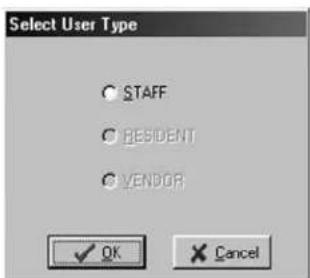
- At the Staff List PC dialog box, simply click on the name of the person to receive this key and click Select.
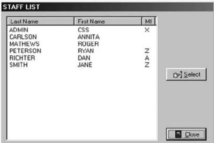
Section 5: Keys
Creating Additional Construction Keys (continued)
- At the Create Construction Key PC dialog box, the name of the person you selected will appear. Place a key in the electronic key encoder now and click OK.

Note: You must keep the key in the electronic key encoder base while the key image spins on the PC screen.
- The PC dialog box will display, "The write operation was successful!" The key is now encoded. Click OK, and then remove the key from the electronic key encoder base.
- The screen will return to the Create Construction Key PC dialog box. If you wish to create additional construction keys, click the button to the right of the box. (This button has a hand pointing to the right.) Follow the procedures previously described.
Note: It is recommended that you limit the number of Construction keys to only those individuals who absolutely need keys. The use of Construction keys are not stored in the lock's memory. When locks are in the construction mode, they cannot be audited.
Section 5: Keys
5.2 Creating Master Keys
After a lock is programmed, a Construction key will no longer provide lock access. You must create Master keys to open any programmed lock on your property, including unit, suite and common access area locks. Master keys are strictly for you and your staff. They are not to be given to residents or even vendors who need access to a number of areas on your property.
Note: Electronic Construction keys can be re-encoded to create new keys.
Note: Not all properties have the option to make Master keys. The option to create a Master key is not available on the software installed at those properties.
Note: The maximum number of duplicate keys is 64. After you have made 64 duplicate keys, you must start over by making a new key for that level.
- Be sure that the PC is turned on, the electronic key encoder device is plugged in an electrical outlet and the USB cable between them is properly attached (see Section 2.5 "Installing the Electronic Key Encoder and Utility Device").
Note: The utility device need not be in the electronic key encoder to create keys.
- To create additional Master keys, click on the Keys menu at the top of the window or the Keys icon.
- Point to Create, then select Master Key.

- At the Create Master Key PC dialog box, select the New Key option if this is the first Master key.
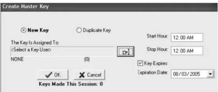
Section 5: Keys
Creating Master Keys (continued)
- The default settings for master keys assign each key for a full 24 hours each day with no expiration date. You may leave the settings if they meet your requirements. However, if you wish to limit the number of hours per day the key will provide access or assign an expiration date, you can do so now. To assign operational times – during the time a new hire is on

probation, for example – adjust the start and stop hours on the PC dialog box. To assign an expiration date, click the open box next to Key Expires. A Date field will appear beneath these words. Enter the desired key expiration date in the Date field.
- Now, you must name the person to whom you wish to assign the key in the box under the words, "The Key Is Assigned To." Click the button to the right of the box. (This button has a hand pointing to the right.) This will display the Select User Type PC dialog box.
Note: Master keys can only be assigned to staff members.
- Click the open circle next to Staff and click OK.

- At the Staff List PC dialog box, any staff members you previously entered into the system will be listed in this box. Simply click on the name of the person to receive this key and click Select.

Section 5: Keys
Creating Master Keys (continued)
- Back at the Create Master Key PC dialog box, the name of the person you selected will appear in the box under the words, "The Key Is Assigned To."
- When you are satisfied with the settings for this key, insert a key into the encoder and click OK.
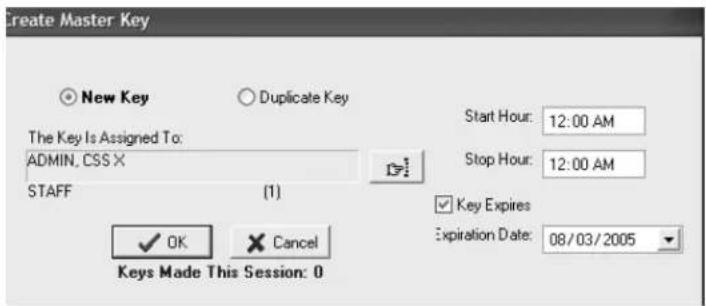

Note: You must keep the key in the electronic key encoder base while the key image spins on the PC screen.
Note: Whenever you select the New Key option, a Warning PC dialog box will appear, indicating that creating a new key will cancel any other keys of the same type. If this is the first key of this type you are creating, click Yes to proceed. Otherwise, click No to return to the Create Master Key PC dialog box and select the Duplicate Key option.

Note: If a key is not currently in the electronic key encoder, the PC will display an error screen until you insert a key into the electronic key encoder.
Note: You must keep the USB cable connected between the electronic key encoder base and the PC while the key image spins on the PC screen. The PC screen will display, "The write operation was successful!"

Section 5: Keys
Creating Master Keys (continued)
- Click OK on the PC dialog box screen message to create additional keys. Follow the procedure described above to continue creating duplicate keys.

The SAM RF System designates every new key created as Key ID 1. Each subsequent key you create as a duplicate key will be designated Key ID 2, Key ID 3, etc. – up to Key ID 64. Carefully assigning key IDs will increase the level of security the SAM RF System provides – allowing you to know exactly who has which keys and helping you make sure that any lost or stolen keys no longer provide access.
Note: The "Keys Made This Session" number at the bottom of the PC dialog box will change to reflect each key you create.
Note: It is recommended that you label each key as it is created to avoid confusion later.
Section 5: Keys
5.3 Creating Additional Duplicate Master Keys
Note: The maximum number of duplicate keys is 64. After you have made 64 duplicate keys, you must start over by making a new key for that level.
- Be sure that the PC is turned on, the electronic key encoder device is plugged in an electrical outlet and the USB cable between them is properly attached (see Section 2.5 "Installing the Electronic Key Encoder and Utility Device").
- To create additional Master keys, click on the Keys menu at the top of the window or the Keys icon.
- Point to Create, then select Master Key.

- At the Create Master Key PC dialog box, it is important to accept (i.e., do not change) the default setting of Duplicate Key because this will NOT be the first master key you are creating.

- If you wish to limit the number of hours per day that this key will provide access, you can do so now. To assign an expiration date – during the time a new hire is on probation, for example – click the open box next to Key Expires. A Date field will appear beneath these words. Simply enter an appropriate date in the Date field.
- At this point, refer to the previous section to continue duplicating Master keys, starting with Step 7.
Section 5: Keys
5.4 Creating Emergency Keys
Emergency keys are programmed to open any lock on your property, including unit, suite and common access area locks. They are strictly for you, your local fire department, or other select emergency personnel.
Note: Not all properties have the option to make Emergency keys. The option to create an Emergency key is not available on the software installed at those properties.
Note: The maximum number of duplicate keys is 64. After you have made 64 duplicate keys, you must start over by making a new key for that level.
- Be sure that the PC is turned on, the electronic key encoder device is plugged in an electrical outlet and the USB cable between them is properly attached (see Section 2.5 "Installing the Electronic Key Encoder and Utility Device").
Note: The utility device need not be in the electronic key encoder to create keys.
-
To create additional Emergency keys, click on the Keys menu at the top of the window or the Keys icon.
-
Point to Create, then select Emergency Key.
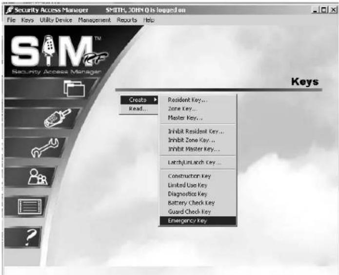
-
At the Create Emergency Key PC dialog box, select the New Key option if this is the first emergency key you create. Emergency keys provide 24-hour access to all unit, suite, and common access locks. Emergency keys do not have expiration dates.
-
Click the button to the right of the box. (This button has a hand pointing to the right.)

Section 5: Keys
Creating Emergency Keys (continued)
- Click the open circle next to Staff and click OK.
Note: Emergency keys can only be assigned to staff members.

- At the Staff List PC dialog box, simply click on the name of the person to receive this key and click Select. Any staff members you previously entered into the system will be listed in this box.
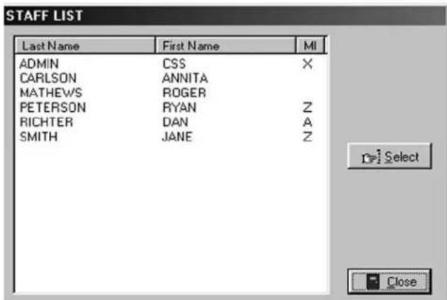
-
Back at the Create Emergency Key PC dialog box, the name of the person you selected will appear in the box under the words, "The Key Is Assigned To."
-
When you are satisfied with the settings for this key, insert a key into the encoder and click OK.


Note: You must keep the key in the electronic key encoder base while the key image spins on the PC screen.
Note: Whenever you select the New Key option, a Warning PC dialog box will appear, indicating that creating a new key will cancel any other keys of the same type. If this is the first key of this type you are creating, click Yes to proceed. Otherwise, click No to return to the Create Emergency Key PC dialog box and select the Duplicate Key option.

Section 5: Keys
Creating Emergency Keys (continued)
Note: If a key is not currently in the electronic key encoder, the PC will display an error screen until you insert a key into the electronic key encoder.
Note: You must keep the USB cable connected between the electronic key encoder base and the PC while the key image spins on the PC screen. The PC screen will display, "The write operation was successful! The Key ID for this key is 1."
Note: The SAM RF System designates every new key created as Key ID 1. Each subsequent key you create as a duplicate key will be designated Key ID 2, Key ID 3, etc. – up to Key ID 64. Carefully assigning key IDs will increase the level of security the SAM RF System provides – allowing you to know exactly who has which keys and helping you make sure that any lost or stolen keys no longer provide access.
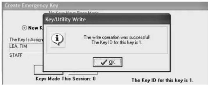
- Click OK on the PC dialog box screen message to create additional keys. Follow the procedure described above to continue creating duplicate keys.
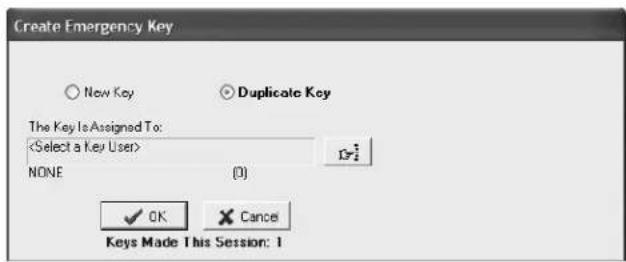
Note: The "Keys Made This Session" number at the bottom of the PC dialog box will change to reflect each key you create.
Note: It is recommended that you label each key as it is created to avoid confusion later.
Section 5: Keys
5.5 Creating Additional Emergency Keys
Note: The maximum number of duplicate keys is 64. After you have made 64 duplicate keys, you must start over by making a new key for that level.
- Be sure that the PC is turned on, the electronic key encoder device is plugged in an electrical outlet and the USB cable between them is properly attached (see Section 2.5 "Installing the Electronic Key Encoder and Utility Device").
Note: The utility device need not be in the electronic key encoder to create keys.
- To create additional Emergency keys, click on the Keys menu at the top of the window or the Keys icon.
- Point to Create, then select Emergency Key.

- At the Create Emergency Key PC dialog box, it is important to accept (i.e., do not change) the default setting of Duplicate Key because this will not be the first master key you are creating.

- At this point, refer to the previous section to continue duplicating Emergency keys, starting with Step 5.
Section 5: Keys
5.6 Creating Zone Keys
Zone keys will open any lock within a specific zone, including common access area locks, unit locks and suite locks. In other words, they are essentially a Master key for a specific zone. Assuming your property has zones, you may decide that managers should only have keys for one or more specific zones.
Note: Not all properties have the option to make Zone keys. The option to create a Zone key is not available on the software installed at those properties.
Note: The maximum number of duplicate keys is 64. After you have made 64 duplicate keys, you must start over by making a new key for that level.
- Be sure that the PC is turned on, the electronic key encoder device is plugged in an electrical outlet and the USB cable between them is properly attached (see Section 2.5 "Installing the Electronic Key Encoder and Utility Device").
Note: The utility device need not be in the electronic key encoder to create keys.
-
To create additional Zone keys, click on the Keys menu at the top of the window or the Keys icon.
-
Point to Create, then select Zone Key.
-
At the Create Zone Key PC dialog box, it is important to select the New Key option if this will be the first zone key you are creating. If this is the first zone key you make, you will see at the top of this PC dialog box in red letters, "No Keys Have Been Made."
-
The default settings for zone keys assign each key for a full 24 hours each day with no expiration date. You may leave the settings if they meet your requirements. However, if you wish to limit the number of hours per day the key will provide access or assign an expiration date, you can do so now. To assign operational times – during the time a new hire is on probation, for example – adjust the start and stop hours on the PC
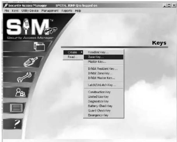
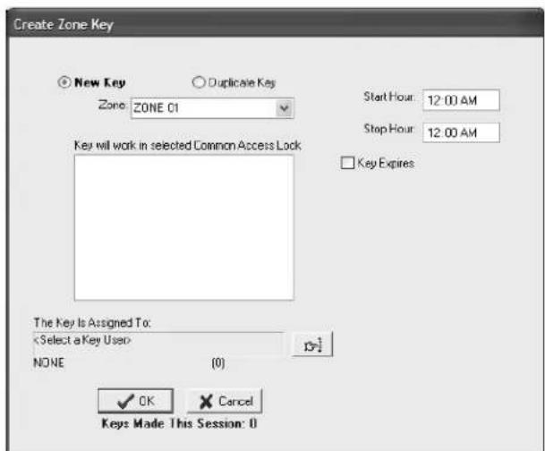
dialog box. To assign an expiration date, click the open box next to Key Expires. A Date field will appear beneath these words. Enter the desired key expiration date in the Date field.
Section 5: Keys
Creating Zone Keys (continued)
- Go to the Zone pull-down box and confirm that you are creating a key for the appropriate zone. All zones within your property will appear in the pull-down box. In fact, the first zone should already be selected and appear in the box. When you have selected the desired zone(s), click OK.

- Now you must name the person to whom you wish to assign the key in the box under the words, "The Key Is Assigned To." Click the button to the right of the box. (This button has a hand pointing to the right.) This will display the Select User Type PC dialog box.
Note: Zone keys can only be assigned to staff members.
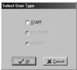
- Click the open circle next to Staff and click OK. This will take you to the Staff List PC dialog box. Any staff members you previously entered into the system will be listed in this box. Simply click on the name of the person to receive this key and click Select.
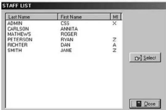
Section 5: Keys
Creating Zone Keys (continued)
-
Back at the Create Zone Key PC dialog box, the name of the person you selected will appear in the box under the words, "The Key Is Assigned To." You will now confirm the default settings for the common access areas for this zone. These default settings were set up in the site design process and will not likely require any changes. However, you may choose to limit select common access lock(s) by a zone key. If so, select the common access locks you wish to assign or unassign the particular key by clicking in the squares next to the inside the common access lock PC dialog box area.
-
When you are satisfied with the settings for this key, insert a key into the encoder and click OK.
![Create Zone Key No Keys Have Been Made Now Key Duplicate Key Zone: ZONE 02 Key will work in selected Common Access Lock POOL1 POOL2 POOL3 SPA [COMMON ACCESS LOCK 05] [COMMON ACCESS LOCK 06] [COMMON ACCESS LOCK 07] [COMMON ACCESS LOCK 08] Start Hour: 12:00 AM Stop Hour: 12:00 AM Key Expires The Key Is Assigned To ADMIN. CSS X STAFF (1) OK Cancel Keys Made This Session: 0](/content/2026/05/932090/images/9227c7835398f1bf746941ed3762587ad8f4a0fd8b62ebcd8b0500ff0dc8d163.jpg)

Note: You must keep the key in the electronic key encoder base while the key image spins on the PC screen.
Note: Whenever you select the New Key option, a Warning PC dialog box will appear, indicating that creating a new key will cancel any other keys of the same type. If this is the first key of this type you are creating, click Yes to proceed. Otherwise, click No to return to the Create Zone Key PC dialog box and select the Duplicate Key option.

Note: If a key is not currently in the electronic key encoder, the PC will display an error screen until you insert a key into the electronic key encoder.
Note: You must keep the USB cable connected between the electronic key encoder base and the PC while the key image spins on the PC screen. The PC screen will display, "The write operation was successful! The KEY ID for this key is 1."
Section 5: Keys
Creating Zone Keys (continued)
The SAM RF System designates every new key created as Key ID 1. Each subsequent key you create as a duplicate key will be designated Key ID 2, Key ID 3, etc. – up to Key ID 64. Carefully assigning key IDs will increase the level of security the SAM RF System provides – allowing you to know exactly who has which keys and helping you make sure that any lost or stolen keys no longer provide access.
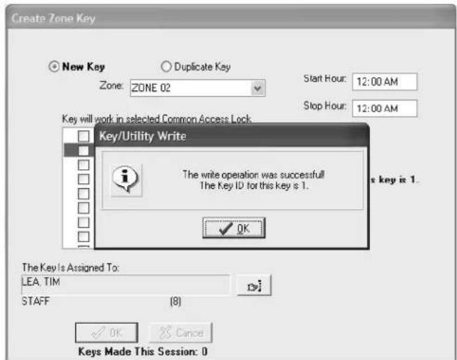
- Click OK on the PC dialog box screen message to create additional keys. Follow the procedure described above to continue creating zone keys.
![Create Zone Key New Key Duplicate Key Zone: ZONE 02 Start Hour: 12:00 AM Stop Hour: 12:00 AM Key will work in selected Common Access Lock P00L1 P00L2 P00L3 SPA [COMMON ACCESS LOCK 05] [COMMON ACCESS LOCK 06] [COMMON ACCESS LOCK 07] [COMMON ACCESS LOCK 08] Key Expires The Key Is Assigned To:](/content/2026/05/932090/images/90836f99c70f25c739bee1aae9bd5da7191e97e98308d44b9835b8cfc1c5e5ef.jpg)
Section 5: Keys
5.8 Creating Latch/Unlatch Keys
The latch/unlatch key allows a common access lock to be unlatched and latched. The first time the latch/unlatch key is used in the lock it will unlatch the lock. When a lock is unlatched, a key is not needed to open the door. The second time the key is used, it will latch the lock. When the lock is latched, you must use a valid key to open the lock. Note: The maximum number of duplicate keys is 64. After you have made 64 duplicate keys, you must start over by making a new key for that level. 1. Be sure that the PC is turned on, the electronic key encoder device is plugged in an electrical outlet and the USB cable between them is properly attached (see Section 2.5 "Installing the Electronic Key Encoder and Utility Device"). Note: The utility device need not be in the electronic key encoder to create keys. 2. Click on the Keys menu at the top of the window or the Keys icon. 3. Point to Create, then select Latch/Unlatch Key.  4. At the Create Latch/Unlatch PC dialog box, it is important to select the New Key option if this will be the first latch/unlatch key you are creating. If this is the first latch/unlatch key you make, you will see at the top of this PC dialog box in red letters, "No Keys Have Been Made." Section 5: Keys
Creating Latch/Unlatch Keys (continued)
5. You must name the person to whom you wish to assign the key in the box under the words, "The Key Is Assigned To." Click the button to the right of the box. (This button has a hand pointing to the right.) This will display the Select User Type PC dialog box. Click the open circle next to Staff and click OK. Note: Latch/Unlatch keys can only be assigned to staff members.  6. At the Staff List PC dialog box, any staff members you previously entered into the system will be listed in this box. Simply click on the name of the person to receive this key and click Select.  7. Back at the Create Latch/Unlatch Key PC dialog box, the name of the person you selected will appear in the box under the words, "The Key Is Assigned To". 8. When you are satisfied with the settings for this key, insert a key into the encoder and click OK.  Note: You must keep the key in the electronic key encoder base while the key image spins on the PC screen. Note: Whenever you select the New Key option, a Warning PC dialog box will appear, indicating that creating a new key will cancel any other keys of the same type. If this is the first key of this type you are creating, click Yes to proceed. Otherwise, click No to return to the Create Latch/Unlatch Key PC dialog box and select the Duplicate Key option.  Note: If a key is not currently in the electronic key encoder, the PC will display an error screen until you insert a key into the electronic key encoder. Note: You must keep the USB cable connected between the electronic key encoder base and the PC while the key image spins on the PC screen. The PC screen will display, "The write operation was successful! The key ID for this key is 1."Section 5: Keys
Creating Latch/Unlatch Keys (continued)
The SAM RF System designates every new key created as Key ID 1. Each subsequent key you create as a duplicate key will be designated Key ID 2, Key ID 3, etc. – up to Key ID 64. Carefully assigning key IDs will increase the level of security the SAM RF System provides – allowing you to know exactly who has which keys and helping you make sure that any lost or stolen keys no longer provide access.  9. Click OK on the PC dialog box screen message to create additional keys. Follow the procedure described above to continue creating duplicate keys.  Note: The "Keys Made This Session" number at the bottom of the PC dialog box will change to reflect each key you create. Note: It is recommended that you label each key as it is created to avoid confusion later.Section 5: Keys
5.9 Creating Additional Latch/Unlatch Keys
Note: The maximum number of duplicate keys is 64. After you have made 64 duplicate keys, you must start over by making a new key for that level. 1. Be sure that the PC is turned on, the electronic key encoder device is plugged in an electrical outlet and the USB cable between them is properly attached (see Section 2.5 "Installing the Electronic Key Encoder and Utility Device"). Note: The utility device need not be in the electronic key encoder to create keys. 2. Click on the Keys menu at the top of the window or the Keys icon. 3. Point to Create, then select Latch/Unlatch Key.  4. At the Create Latch/Unlatch Key PC dialog box, it is important to accept (i.e., do not change) the default setting of Duplicate Key because this will now be a duplicate latch/unlatch key.  5. At this point, refer to the previous section to continue duplicating latch/unlatch keys until you have enough keys to give to the appropriate number of staff members. Be sure to assign them as duplicate keys to create a new key ID for each staff member.Section 5: Keys
5.10 Preventing Staff Access
Merely deleting staff members from the SAM RF System is not enough to ensure the security of your property. It is also very important that you collect whatever keys they might have in their possession. If former staff members do not relinquish their keys, they can continue to gain access to common access areas or to your residents' units. To ensure the security of your property whether or not you have collected any keys in former staff members' possession, you should reprogram the locks where these staff members previously had access. To reprogram these locks, you need an Inhibit key. An Inhibit key is programmed to tell a lock to ignore keys with specific key IDs. If you assign key IDs carefully in the key creation process, the inhibiting process will be easy.Section 5: Keys
5.11 Creating an Inhibit Master Key
If a staff member loses a key, the security risk is far more serious than when a resident loses a key because staff members' keys are usually either Master keys or Zone keys, which provide access to more than just a single unit. To ensure the security of your property your residents, you must carefully reprogram all the locks that the lost key previously opened. To reprogram these locks, you'll need either an Inhibit Master key or an Inhibit Zone key with the ID number or numbers you wish to inhibit. Note: The maximum number of duplicate keys is 64. After you have made 64 duplicate keys, you must start over by making a new key for that level. 1. Be sure that the PC is turned on, the electronic key encoder device is plugged in an electrical outlet and the USB cable between them is properly attached (see Section 2.5 "Installing the Electronic Key Encoder and Utility Device"). Note: The utility device need not be in the electronic key encoder to create keys. 2. Click on the Keys menu at the top of the window or the Keys icon. 3. Point to Create, then select Inhibit Master Key.  4. At the Create Inhibit Master Key PC dialog box, simply click in the box to the left of the staff member(s) whose key(s) you wish to inhibit. 5. Name the person to whom you wish to assign the inhibit key in the box under The Key Is Assigned To. Click the button to the right of the box. (This button has a hand pointing to the right.) Section 5: Keys
Creating an Inhibit Master Key (continued)
6. At the Select User Type PC dialog box, click the open circle next to Staff and click OK. Note: Inhibit Master keys can only be assigned to staff members.  7. Staff members you previously entered into the system will be listed in this box. Simply click on the name of the person to receive this new key and click Select.  8. Back at the Create Inhibit Master Key PC dialog box, the name of the person you selected will appear in the box under The Key Is Assigned To. When you are satisfied with the settings for this inhibit Master key, insert a key, and then click OK.  Note: You must keep the key in the electronic key encoder base while the key image spins on the PC screen. Note: If a key is not currently in the electronic key encoder, the PC will display an error screen until you insert a key into the electronic key encoder. Note: You must keep the USB cable connected between the electronic key encoder base and the PC while the key image spins on the PC screen. The PC screen will display, "The write operation was successful!"Section 5: Keys
Creating an Inhibit Master Key (continued)
9. Click OK on the PC dialog box screen message to create additional keys. Follow the procedure described above to continue creating duplicate keys. Note: Depending upon the size of your property, you may wish to create several Inhibit Master keys and enlist the assistance of other staff members to help you reprogram these locks. 10. Reprogramming Locks – Now that you have created an Inhibit Master key, it is necessary to go to each and every unit, suite and common access lock on your property and insert the Inhibit Master key. This process will reprogram the locks to no longer provide access to the lost key ID. Section 5: Keys
5.12 Creating an Inhibit Zone Key
Note: The maximum number of duplicate keys is 64. After you have made 64 duplicate keys, you must start over by making a new key for that level. 1. Be sure that the PC is turned on, the electronic key encoder device is plugged in an electrical outlet and the USB cable between them is properly attached (see Section 2.5 "Installing the Electronic Key Encoder and Utility Device"). Note: The utility device need not be in the electronic key encoder to create keys. 2. Click on the Keys menu at the top of the window or the Keys icon. 3. Point to Create, then select Inhibit Zone Key.  4. At the Create Inhibit Zone Key PC dialog box, go to the Zone pull-down box and confirm that you are creating an inhibit key for the appropriate zone. If you set up zones correctly in the site design process, all zones within your property will appear in the pull-down box. Select the appropriate zone. 5. In the Select IDs to Inhibit box is a listing of all zone key IDs created, along with the name of the staff member to whom you wish to assign each key. Simply click in the box to the left of the staff member(s) whose key(s) you wish to inhibit. 6. Name the person to whom you wish to assign the key in the box under The Key Is Assigned To. Click the button to the right of the box. (This button has a hand pointing to the right.) Section 5: Keys
Creating an Inhibit Zone Key (continued)
7. At the Select User Type PC dialog box, click the open circle next to Staff and click OK. Note: Inhibit Zone keys can only be assigned to staff members.  8. At the Staff List PC dialog box, staff members you previously entered into the system will be listed in this box. Simply click on the name of the person to receive this key and click Select.  9. Back at the Create Inhibit Zone Key PC dialog box, the name of the person you selected will appear in the box under The Key Is Assigned To. When you are satisfied with the settings for this Inhibit Zone key, insert the key into the encoder and click OK.  Note: You must keep the key in the electronic key encoder base while the key image spins on the PC screen. Note: If a key is not currently in the electronic key encoder, the PC will display an error screen until you insert a key into the electronic key encoder. Note: You must keep the USB cable connected between the electronic key encoder base and the PC while the key image spins on the PC screen. The PC screen will display, "The write operation was successful!" Click OK on the PC message to continue creating inhibit zone keys. 10. Reprogramming Locks – Now that you have created an Inhibit Zone key, it is necessary to go to each and every unit, suite, and common access lock in the zone and insert the Inhibit Zone key. This will reprogram the locks to no longer provide access to the lost key ID.  Note: Depending upon the size of your zone, you may wish to create several Inhibit Zone keys and enlist the support of other staff members to help you reprogram these locks.Section 5: Keys
5.13 Creating Guard Check Keys
The Guard Check key allows your staff or security to register their patrol throughout your property. The non-opening key is programmed to function in all of your common access locks. The key can be read upon return from the locks. You can view and print reports of the lock names and the times the Guard Check keys were inserted. The report will show the last 25 common access locks in which the key was used. After a key is read, it should be erased. Note: The maximum number of duplicate keys is 64. After you have made 64 duplicate keys, you must start over by making a new key for that level. 1. Be sure that the PC is turned on, the electronic key encoder device is plugged in an electrical outlet and the USB cable between them is properly attached (see Section 2.5 "Installing the Electronic Key Encoder and Utility Device"). Note: The utility device need not be in the electronic key encoder to create keys. 2. Click on the Keys menu at the top of the window or the Keys icon. 3. Point to Create, then select Guard Check Key.  4. At the Create Guard Check Key PC dialog box, you must name the person to whom you wish to assign the key in the box under the words, "The Key Is Assigned To." Click the button to the right of the box. (This button has a hand pointing to the right.)  5. At the Select User Type PC dialog box, click the open circle next to Staff and click OK. Note: Guard Check keys can only be assigned to staff members. Section 5: Keys
Creating Guard Check Keys (continued)
6. At the Staff List PC dialog box, simply click on the name of the person to receive this key and click Select. Any staff members you previously entered into the system will be listed in this box.  7. Back at the Create Guard Check Key PC dialog box, the name of the person you selected will appear in the box under The Key Is Assigned To. When you are satisfied with the settings for this key, insert a key into the encoder, and then click OK.   Note: You must keep the key in the electronic key encoder base while the key image spins on the PC screen. Note: If a key is not currently in the electronic key encoder, the PC will display an error screen until you insert a key into the electronic key encoder. Note: You must keep the USB cable connected between the electronic key encoder base and the PC while the key image spins on the PC screen. The PC screen will display, "The write operation was successful!" Note: The "Keys Made This Session" number at the bottom of the PC dialog box will change to reflect each key you create this session. 8. Click OK on the PC dialog box screen message to create additional keys for staff members. Follow the procedure described above.  Note: It is recommended that you label each key as it is created to avoid confusion later.Section 5: Keys
5.14 Reading the Guard Check Key
When the key is returned, it should be read to view or print the report of where the key was used. The report will show the last 25 common access locks in which the key was used. Note: The maximum number of duplicate keys is 64. After you have made 64 duplicate keys, you must start over by making a new key for that level. 1. Be sure that the PC is turned on, the electronic key encoder device is plugged in an electrical outlet and the USB cable between them is properly attached (see Section 2.5 "Installing the Electronic Key Encoder and Utility Device"). 2. Insert the Guard Check key into the electronic encoder. 3. Point to the Keys pull-down menu and select Read. Note: If the key is not currently in the electronic key encoder, the PC will display an error screen until you insert a key into the electronic key encoder. Note: You must keep the USB cable connected between the electronic key encoder base and the PC while the key image spins on the PC screen.  4. At the Key Read screen, you will see the key type, who the key was assigned to, the status of the key and who made the key. Click on Report. Section 5: Keys
Reading the Guard Check Key (continued)
5. At the Output Options PC dialog box, click OK.
Within a few moments, the report will appear on screen. The Guard Check Report will show the Lock Name, Date/Time and Day of Week the key was used.  6. When finished viewing the report, click on File, then Exit. This will return you to the Key Read screen. If you would like, you can erase the key by clicking on the Erase box on the bottom right of the screen. Once the key is erased, click Close to return to the SAM RF System main menu screen. Section 5: Keys
5.15 Creating Diagnostics Keys
The Diagnostics key is designed to help analyze and reveal why a key will not gain entry. This is a non-opening key that may be used in any lock on the property. If a lock does not allow access for its programmed key, program a Diagnostics key and insert it into the lock in question. Return the Diagnostics key to the PC for a diagnostics report. Note: The key that will not gain access must be the last key used in the lock prior to the Diagnostics key to secure information. Note: The maximum number of duplicate keys is 64. After you have made 64 duplicate keys, you must start over by making a new key for that level. 1. Be sure that the PC is turned on, the electronic key encoder device is plugged in an electrical outlet and the USB cable between them is properly attached (see Section 2.5 "Installing the Electronic Key Encoder and Utility Device"). Note: The utility device need not be in the electronic key encoder to create keys. 2. Click on the Keys menu at the top of the window or the Keys icon. 3. Point to Create, then select Diagnostics Key.  4. At the Create Diagnostics Key PC dialog box, you must name the person to whom you wish to assign the key in the box under the words, "The Key Is Assigned To." Click the button to the right of the box. (This button has a hand pointing to the right.)  5. At the Select User Type PC dialog box, click the open circle next to Staff and click OK. Note: Diagnostics keys can only be assigned to staff members. Section 5: Keys
Creating Diagnostics Keys (continued)
6. At the Staff List PC dialog box, any staff members you previously entered into the system will be listed in this box. Simply click on the name of the person to receive this key and click Select.  7. Back at the Create Diagnostics Key PC dialog box, the name of the person you selected will appear in the box under The Key Is Assigned To. When you are satisfied with the settings for this key, insert a key in the encoder and click OK.   Note: You must keep the key in the electronic key encoder base while the key image spins on the PC screen. Note: If a key is not currently in the electronic key encoder, the PC will display an error screen until you insert a key into the electronic key encoder. Note: You must keep the USB cable connected between the electronic key encoder base and the PC while the key image spins on the PC screen. The PC screen will display, "The write operation was successful!" Note: The "Keys Made This Session" number at the bottom of the PC dialog box will change to reflect each key you create this session. 8. Click OK on the PC dialog box screen message to create additional keys for staff members. Follow the procedure described above. Note: It is recommended that you label each key as it is created to avoid confusion later. Section 5: Keys
5.16 Reading the Diagnostics Key
After the Diagnostics key has been used in the lock, you will need to read it to get the error as to why the key did not work. 1. Be sure that the PC is turned on, the electronic key encoder device is plugged in an electrical outlet and the USB cable between them is properly attached (see Section 2.5 "Installing the Electronic Key Encoder and Utility Device"). 2. Insert the Diagnostics key into the electronic key encoder. 3. Point to the Keys pull down menu and select Read. Note: If a key is not currently in the electronic key encoder, the PC will display an error screen until you insert a key into the electronic key encoder. Note: You must keep the USB cable connected between the electronic key encoder base and the PC while the key image spins on the PC screen. When the key is read it will automatically display the Key Read PC dialog box.  4. At the Key Read screen, you will see the key type, who the key was assigned to, the status of the key and who made the key. Below that is the Diagnostic Key Information. This will show the error code number and a brief description explaining why the key did no work in the lock. If you would like, you can erase the key by clicking on the Erase box on the bottom right of the screen. Once the key is erased, click Close to return to the SAM RF System main menu. Section 5: Keys
5.17 Creating Battery Check Keys
The Battery Check key is a non-opening key that is designed to check the battery voltage in the lock. If the lock's batteries have 5.0 volts or more when the Battery Check key is used, the lock light will display one green light. If the lock's batteries have less than 5.0, volts, the lock will display one red light. This means you must replace the batteries in the lock. The Battery Check key never expires. It can be used on any lock on the property. Note: The maximum number of duplicate keys is 64. After you have made 64 duplicate keys, you must start over by making a new key for that level. 1. Be sure that the PC is turned on, the electronic key encoder device is plugged in an electrical outlet and the USB cable between them is properly attached (see Section 2.5 "Installing the Electronic Key Encoder and Utility Device"). Note: The utility device need not be in the electronic key encoder to create keys. 2. Click on the Keys menu at the top of the window or the Keys icon. 3. Point to Create, then select Battery Check Key.  4. At the Create Battery Check Key PC dialog box, you must name the person to whom you wish to assign the key in the box under The Key Is Assigned To. Click the button to the right of the box. (This button has a hand pointing to the right.)  5. At the Select User Type PC dialog box, click the open circle next to Staff and click OK. Note: Battery Check keys can only be assigned to staff members. Section 5: Keys
Creating Battery Check Keys (continued)
6. At the Staff List PC dialog box, any staff members you previously entered into the system will be listed in this box. Simply click on the name of the person to receive this key and click Select.  7. Back at the Create Battery Check Key PC dialog box, the name of the person you selected will appear in the box under the words, "The Key Is Assigned To." When you are satisfied with the settings for this key, insert a key in the encoder and click OK.   Note: You must keep the key in the electronic key encoder base while the key image spins on the PC screen. Note: If a key is not currently in the electronic key encoder, the PC will display an error screen until you insert a key into the electronic key encoder. Note: You must keep the USB cable connected between the electronic key encoder base and the PC while the key image spins on the PC screen. The PC dialog screen will display, "The write operation was successful!" Note: The "Keys Made This Session" number at the bottom of the PC dialog box will change to reflect each key you create this session. 8. Click OK on the PC dialog box screen message to create additional keys for staff members. Follow the procedure described above. Note: It is recommended that you label each key as it is created to avoid confusion later. Section 5: Keys
5.18 Limited Use/Vendor Keys
Limited Use keys are for vendors whose product and service companies help keep your property running smoothly or staff members and potential residents who may wish to view a unit or common access area. A vendor might provide pool-cleaning services, sending one or more employees to your property on a regular basis. A vendor might also provide a one-time service, such as a plumber replacing a broken pipe in a resident's shower. Limited Use keys provide access to a designated area (or areas) for a limited period of time that you define as you create the key. The Limited Use key can be programmed to provide access to a single location – such as a specific common access area or one specific unit – or up to 20 units per key. Rather than provide a Master key to a vendor – giving him or her access to more areas than necessary – you can create a vendor key, also known as a Limited Use key. Limited Use keys provide access for a specific vendor to a designated area (or areas) for a finite period of time, up to 24 hours. Before creating Limited Use keys, it is highly recommended that you register the specific vendor, as well as that vendor's employee(s), in the SAM RF System. This will allow you to assign Limited Use keys appropriately and to track these keys if necessary later.Section 5: Keys
5.19 Creating Limited Use/Vendor Keys
Note: The maximum number of duplicate keys is 64. After you have made 64 duplicate keys, you must start over by making a new key for that level. 1. Be sure that the PC is turned on, the electronic key encoder device is plugged in an electrical outlet and the USB cable between them is properly attached (see Section 2.5 "Installing the Electronic Key Encoder and Utility Device"). Note: The utility device need not be in the electronic key encoder to create keys. 2. Click on the Keys menu at the top of the window or the Keys icon. 3. Point to Create, then select Limited Use Key.  4. In the Create Limited Use Key PC dialog box, the first step is to select the locks that this key will open. You can choose a single unit or any combination of units up to a total of 20, as well as common access areas. When the Limited Use key is read, it will show the last 40 locks in which the key was used. Note: For the common access areas, you can click Mark All to easily select all common access locks. If you intend to select eight out of 10 of these locks, for example, you can Mark All, then click the two unwanted areas to unselect them. 5. Next, if you wish a Limited Use key to have one-time access, click the square next to One Shot Key. This will program the key to work for only one unit lock and allow it to open this lock only once. 6. You will need to assign a date and expiration time for the Limited Use key. First, click on Valid Date and assign the date you wish the key to expire (this date can be in the future) if a future date is selected; the key will not begin working until 12:01 a.m. on that date. Next, go to Expiration Time and assign the time you wish the key to expire. Note: Any unit numbers that appear in bold print have an open or pending work order. To view the work order, double click on the unit number. See Sections 4.10-13 for detailed information on work orders. Section 5: Keys
Creating Limited Use/Vendor Keys (continued)
7. You must name the person to whom you wish to assign the key in the box under The Key Is Assigned To. Click the button to the right of the box. (This button has a hand pointing to the right.) This will display the Select User Type PC dialog box.  8. Click the open circle next to Vendor and click OK. This will take you to the Vendor Company List PC dialog box.  9. Any vendor companies previously entered into the system will be listed in this box. Click on the name of the vendor, and then click Employees. 10. Click on the name of the vendor employee, and then click Select. This will take you back to the Create Limited Use Key PC dialog box. Section 5: Keys
Creating Limited Use/Vendor Keys (continued)
11. The name of the vendor employee you selected will now appear in the box under The Key Is Assigned To. When you are satisfied with the settings for this key, click OK.   Note: You must keep the key in the electronic key encoder base while the key image spins on the PC screen. Note: If a key is not currently in the electronic key encoder, the PC will display an error screen until you insert a key into the electronic key encoder. Note: You must keep the USB cable connected between the electronic key encoder base and the PC while the key image spins on the PC screen. The PC dialog screen will display, "The write operation was successful!" 12. Click OK on the PC dialog box screen message to create additional limited use keys. If you have more than one vendor or vendor employee needing access, repeat the process for creating a Limited Use key. Be sure to assign each key to a specific vendor employee to be able to track the key if necessary. Section 5: Keys
5.20 Reading Limited Use Keys
After a Limited Use key has been issued and used, you can read the key. Reading the key will allow you to save the audits from the key. The audits will allow you to see where and when the key was used. 1. Be sure that the PC is turned on, the electronic key encoder device is plugged in an electrical outlet and the USB cable between them is properly attached (see Section 2.5 "Installing the Electronic Key Encoder and Utility Device"). Note: The utility device need not be in the electronic key encoder to create keys. 2. Click on the Keys menu at the top of the window or the Keys icon. 3. Click on Read. Note: If a key is not currently in the electronic key encoder, you will be prompted to insert a key into the electronic key encoder now. You must keep all the USB cable connected between the electronic key encoder base and the PC while the key image spins on the PC screen.  4. The Key Read PC dialog box displays the key type, to whom the key was assigned, the status of the key, the expiration date, who made the key and the common access locks and unit numbers the key was programmed to access. At the bottom left of the screen there is a box to Save Audits. If you click on the box it will display the Confirmation Requested PC dialog box. Section 5: Keys
Reading Limited Use Keys (continued)
5. To save the report for later viewing, click Yes. This will display the Success PC dialog box.  6. The Success PC Dialog Box confirms that the operation was successful and the report was saved. Click OK. Note: If you save the audits, you can print or view the Limited Used Audit Report. The Limited Use Audit will show the last 40 times the key was used. For details on the Limited Use Audit Report, see Section 7.6. Note: It is not necessary to replace lost or stolen limited use keys if they have reached their expiration date and time. Section 5: Keys
5.21 Creating Resident/Unit Keys
Note: The maximum number of duplicate keys is 64. After you have made 64 duplicate keys, you must start over by making a new key for that level. 1. Be sure that the PC is turned on, the electronic key encoder device is plugged in an electrical outlet and the USB cable between them is properly attached (see Section 2.5 "Installing the Electronic Key Encoder and Utility Device"). Note: The utility device need not be in the electronic key encoder to create keys. 2. Click on the Keys menu at the top of the window or the Keys icon. 3. Point to Create, then select Resident Key.  4. At the Create Resident/Unit Key PC dialog box, your first task is to select either the New Key option or the Duplicate Key option. As with master keys, you must choose the New Key option each time you create the first key for a specific unit and the Duplicate Key option for subsequent keys created for the same unit. 5. The next step is to go to the Unit pull-down box and select the appropriate unit. Units within your property that are programmed in the SAM RF System will appear in the pull-down box. Section 5: Keys
Creating Resident/Unit Keys (continued)
6. The key will have no expiration date unless you assign one. If you wish to assign an expiration date, click the box next to Key Expires. A Date field will appear beneath these words. Enter the desired key expiration date in the Date field. You must name the person to whom you wish to assign the key in the box under The Key Is Assigned To. Click the button to the right of the box. (This button has a hand pointing to the right.)  7. Assuming you are creating a key for a resident, click the open circle next to Resident and click OK. Note: Resident keys can be assigned to either staff members or residents.  8. This will take you to the Resident List PC dialog box. Any residents registered into the system for that particular unit will be listed in this box. Simply click on the name of the person to receive this key and click Select. Note: To add a resident into the system, see Section 4.7 "Adding Residents to the SAM RF System". Section 5: Keys
Creating Resident/Unit Keys (continued)
9. Back at the Create Resident Key PC dialog box, the name of the person you selected will appear in the box under the words, "The Key Is Assigned To." Select the common access locks you wish to add to the resident key you are programming. Place the cursor in the box to the left of the common access locks you wish to assign to the resident and click. A check mark will appear. When you are satisfied with the settings for this key, click OK.   Note: You must keep the key in the electronic key encoder base while the key image spins on the PC screen. Note: Whenever the New Key option is selected, a Warning PC dialog box will appear, indicating that creating a new key will cancel any other keys of the same type. If this is indeed the very first key of this type you are creating, click Yes to proceed. Otherwise, click No to return to the Create Resident/Unit Key PC dialog box and select the Duplicate Key option.  Note: If a key is not currently in the electronic key encoder, the PC will display an error screen until you insert a key into the electronic key encoder. Note: You must keep the USB cable connected between the electronic key encoder base and the PC while the key image spins on the PC screen. The PC screen will display, "The write operation was successful! The key ID for this key is 1." 10. Click OK on the PC dialog box screen message to create additional resident keys. Follow the procedure described above until you have enough keys to give to the appropriate number of residents. Be sure to assign additional keys created for the same unit as duplicate keys (to create a new key ID for each resident) and to carefully label them for each specific resident. Section 5: Keys
5.22 Creating Additional Duplicate Resident/Unit Keys
Note: The maximum number of duplicate keys is 64. After you have made 64 duplicate keys, you must start over by making a new key for that level. 1. Be sure that the PC is turned on, the electronic key encoder device is plugged in an electrical outlet and the USB cable between them is properly attached (see Section 2.5 "Installing the Electronic Key Encoder and Utility Device"). Note: The utility device need not be in the electronic key encoder to create keys. 2. Click on the Keys menu at the top of the window or the Keys icon. 3. Point to Create, then select Resident Key.  4. At the Create Resident Key PC dialog box, it is important to accept (i.e., do not change) the default setting of Duplicate Key because this will now be a duplicate resident key. 5. At this point, please reference "Resident/Unit Key Options" and "Encoding the Resident/Unit Key" earlier in this section to continue duplicating resident keys until you have enough keys to give to the appropriate number of residents. Be sure to assign them as duplicate keys to create a new key ID for respective residents. Section 5: Keys
5.23 Preventing Resident Access
Merely deleting residents from the SAM RF System is not enough to ensure the security of your property. It is also very important that you collect whatever keys former residents might have in their possession. If former residents do not relinquish their keys, they can continue to gain access to common access areas and to their former unit(s). To ensure the security of your property AND the security of the new residents of that unit, it is important to make sure that any keys in a former resident's possession will no longer provide access. To prevent access, you must reprogram the locks that the residents previously had access to. To reprogram these locks, you need to create an Inhibit Resident key. If a new resident will be moving in immediately you do not need to create an Inhibit Resident key. When the new Resident key is made and used in the lock(s) it will invalidate the previous Resident(s) keys.Section 5: Keys
5.24 Replacing Lost Resident Keys
Note: Replacing lost Resident keys is discussed in this section. Replacing lost Master keys and Zone keys (Staff keys) is discussed in Sections 5.11 and 5.12. One of the tasks you will perform most often with the SAM RF System is replacing keys lost by either staff or residents. When keys are lost, there are two ways to ensure the security of the property. First, you may choose to create a new key for each resident. Refer to Section 5.21 to create a new Resident key for each resident and use the keys in the lock immediately. Alternately, you will need to create replacement keys and visit the lock to inhibit the lost key as discussed in this section. Note: When there is only one resident in a unit, replacing that person's key is a fairly simple process. Simply create a new key for the resident, and once the key is used in the lock(s), it will invalidate the lost key. However, when several people reside in a unit, a key assigned specifically to one of the residents may end up being used by another. When replacing a lost key in the case of multiple residents, it is critical that you determine which key is actually lost. The best way to determine exactly which key is lost is to have all the other residents of that unit bring their keys to the office so that you can read each key using the electronic key encoder. This will provide information as to each key's ID and to whom it is assigned.Reading Resident Keys
1. Be sure that the PC is turned on, the electronic key encoder device is plugged in an electrical outlet and the USB cable between them is properly attached (see Section 2.5 "Installing the Electronic Key Encoder and Utility Device"). Note: The utility device need not be in the electronic key encoder to create keys. 2. Click on the Keys menu at the top of the window or the Keys icon. 3. Point to Create, then select Read. Note: If a key is not currently in the electronic key encoder, you will be prompted to insert a key into the electronic key encoder now. You must keep all the USB cable connected between the electronic key encoder base and the PC while the key image spins on the PC screen. Section 5: Keys
Replacing Lost Resident Keys (continued)
The Key Read PC dialog box will then appear and display the type of key, to whom the key is assigned, the status of the key, the expiration date, the unit number and the key ID. In addition you will see the staff member who made the key and the common access locks it was allowed to access. Once you have determined which resident/unit keys are accounted for, you will know exactly which key ID is missing. However, before you create a replacement key, it is essential that you first create an Inhibit Resident key. Creating an Inhibit Resident Key
An Inhibit Resident key is programmed to tell a lock to ignore keys with specific key IDs. In the process of making an Inhibit Resident key, the SAM RF System will be programmed with the knowledge that a specific resident key is no longer a valid key ID. When you create the Inhibit Resident key, it will be programmed with the invalid key ID and its information. As the Inhibit key is used, it will automatically program each lock to ignore the invalid key ID. This is why it is so important to determine which key is actually lost. If you are not certain exactly which key ID is lost, you might invalidate the wrong key. 1. Be sure that the PC is turned on, the electronic key encoder device is plugged in an electrical outlet and the USB cable between them is properly attached (see Section 2.5 "Installing the Electronic Key Encoder and Utility Device"). Note: The utility device need not be in the electronic key encoder to create keys. 2. Click on the Keys menu at the top of the window or the Keys icon. 3. Point to Create, then select Inhibit Resident Key. Section 5: Keys
Replacing Lost Resident Keys (continued)
4. At the Create Inhibit Resident Key PC dialog box, your first task is to select the appropriate unit in the pull-down box. Once you have selected the unit in question, the Select IDs to Inhibit box lists all resident key IDs created for that particular unit, along with the names of the residents each key is assigned to. Simply click in the box to the left of the resident(s) whose key(s) you wish to inhibit. Click the button to the right of the box with the message "This Key Is Assigned To." (This button has a hand pointing to the right.) Note: If more than one Resident key is lost, you can select more than one key ID to inhibit.  5. To choose a staff member to assign this key to, click the open circle next to Staff and click OK. This will take you to the Staff List PC dialog box. To choose a resident to assign this key to, click the open circle next to Resident and click OK. Note: Inhibit Resident keys can be assigned to staff members or residents.  6. This will take you to the Resident List PC dialog box. Click on the name of the person who will be assigned this key and click Select. Section 5: Keys
Replacing Lost Resident Keys (continued)
7. Back at the Create Inhibit Resident Key PC dialog box, the name of the person you selected will appear in the box under the words, "The Key Is Assigned To." 8. When you are satisfied with the settings for this Inhibit Resident key, insert a key into the encoder and click OK.   Note: You must keep the key in the electronic key encoder base while the key image spins on the PC screen. Note: If a key is not currently in the electronic key encoder, the PC will display an error screen until you insert a key into the electronic key encoder. Note: You must keep the USB cable connected between the electronic key encoder base and the PC while the key image spins on the PC screen. The PC dialog screen will display, "The write operation was successful!" 9. Click OK on the PC message to continue creating Inhibit Resident keys if you wish. Note: "The Keys Made This Session" number at the bottom of the PC dialog box will change to reflect each Inhibit Resident key you create. Now that you have created the Inhibit Resident key, you have updated the SAM RF System as to which resident key IDs are no longer valid. You can immediately create a replacement Resident key. 10. Reprogramming Locks To ensure the security of your property, all locks that a lost key once opened must be reprogrammed to ignore that key from now on.  IMPORTANT: You will need to insert the Inhibit Resident key into that resident's unit lock, suite lock (if applicable) and all common access locks on your property. This will reprogram the locks to no longer provide access to any of the key IDs selected.Section 5: Keys
5.25 Creating a Replacement Resident Key
Note: The maximum number of duplicate keys is 64. After you have made 64 duplicate keys, you must start over by making a new key for that level. 1. Be sure that the PC is turned on, the electronic key encoder device is plugged in an electrical outlet and the USB cable between them is properly attached (see Section 2.5 "Installing the Electronic Key Encoder and Utility Device"). Note: The utility device need not be in the electronic key encoder to create keys. 2. Click on the Keys menu at the top of the window or the Keys icon. 3. Point to Create, then select Resident Key.  4. In the Create Resident/Unit Key PC dialog box, it is extremely important to accept the default Duplicate Key option. Selecting the New Key option will invalidate ALL other Resident keys for this unit. 5. At this point, please reference "Resident Key Options" and "Encoding the Resident Key" earlier in this section to continue duplicating replacement Resident keys until you have enough keys. Be sure to assign them as duplicate keys to create a new key ID for respective residents and/or staff members. SAM® RF
Operations Manual
Section 6:
Locks
All information contained herein, including but not limited to product pricing and other intellectual property, is confidential and intended for the sole use of the addressee(s) so named. Any misuse of this confidential information contained herein may result in legal action by Computerized Security Systems dba SAFLOK and its parent company.Section 6: Locks
6.1 InSync Locks
There are several different InSync locks available for use with the SAM RF system. Each lock type is shown below with a description of how they operate.D (Unit or Suite) Lock
The D Lock is a battery operated deadbolt lock that is mounted above the passage latch lock on a door. natural_image
Technical line drawings of three different door lock components (boxed, side, and oval) with no visible text or symbols.Unlocking your door from the outside
1. Fully insert your RFID key into the lock port. 2. Wait until the GREEN light flashes once. 3. Rotate the key as you would a standard mechanical dead bolt. Locking and unlocking your door from the inside
- To lock the door from the inside, rotate the thumb turn to lock the dead bolt. - To unlock the door from the inside, the thumb turn in the opposite direction.Locking your door from the outside
1. Shut the door, then insert your key into the lock port. 2. Wait until the GREEN light flashes once. 3. Rotate the key to extend the dead bolt. Section 6: Locks
InSync Locks (continued)
I (Unit or Suite) Lock
The I Lock is a stand-alone, battery operated, interconnected cylindrical latch and deadbolt lock. natural_image
Technical line drawings of three different door lock components (no text or symbols)Unlocking your door from the outside
1. Fully insert your RFID key into the lock port. 2. Wait until the GREEN light flashes once. 3. Rotate the key as you would a standard mechanical dead bolt. 4. Rotate the lever to open the door. Locking and unlocking your door from the inside
- To lock the door from the inside, rotate the thumb turn to lock the dead bolt. - To unlock the door from the inside, rotate the inside lever to retract the latch and dead bolt simultaneously. Rotating the outside lever retracts the latch only.Locking your door from the outside
1. Pull the door shut, then insert your key into the lock port. 2. Wait until the GREEN light flashes once. 3. Rotate the key to extend the dead bolt. Section 6: Locks
InSync Locks (continued)
M Unit Lock
The M Unit Lock is a stand-alone, battery operated, full mortise lock with a latch, automatic deadbolt and thumb turn on the inside. Note: The door will remain unlocked until a key is inserted from the outside or the thumb turn is rotated from the inside. natural_image
Technical line drawings of three different door lock components (no text or symbols)Unit Configuration
Unlocking your door from the outside
1. Fully insert your RFID key into the lock port. 2. Wait until the GREEN light flashes once. 3. Rotate the lever downward to retract the latch bolt and the dead bolt to open the door. Locking and unlocking the door from the inside
To lock the door from the inside, rotate the thumb turn to a position halfway between vertical and horizontal. To unlock the door from the inside, rotate the lever downward or return the thumb turn to a vertical position.  Note: The thumb turn in a vertical position does not always indicate that the door is unlocked; it could be locked from the outside in this condition.Locking your door from the outside
1. Pull the door shut and insert the key into the lock port. 2. Wait unit the RED light flashes once. Section 6: Locks
InSync Locks (continued)
M Suite Lock
The M Suite Lock is a stand-alone, battery operated, full mortise lock with a latch and an automatic deadbolt. InSync M locks for suite configuration have no thumb turn. Suite locks cannot be left unlocked. Note: The lock will latch/lock immediately after the door is opened. natural_image
Technical line drawings of three different door lock components (no text or symbols)Unlocking your door from the outside
1. Fully insert your RFID key into the lock port. 2. Wait until the GREEN light flashes once. 3. Rotate the lever downward to retract the latch bolt and the dead bolt to open the door. Section 6: Locks
InSync Locks (continued)
L Unit Lock
The L lock is a stand-alone, battery operated, cylindrical latch lock with a thumb turn on the inside. natural_image
Technical line drawings of three different door lock components (no text or symbols)Unlocking your door from the outside
1. Fully insert your RFID key into the lock port. 2. Wait until the GREEN light flashes once. 3. Rotate the lever downward to retract the latch bolt to open the door. Locking and unlocking the door from the inside
To lock the door from the inside, rotate the thumb turn to the horizontal position. To unlock the door from the inside, rotate the lever downward or return the thumb turn to the vertical position. Notes:
1. If the lever is used when the door is locked, the thumb turn will always return to the vertical position and the door will remain unlocked. To lock the door from the outside, insert the key and wait for the RED light to flash once. 2. If the door is locked from the inside and entry if made from the outside, the thumb turn will remain in the horizontal position and the door will re-lock in approximately five seconds.Locking your door from the outside
1. Pull the door shut and insert the key into the lock port. 2. Wait until the RED light flashes once. Section 6: Locks
InSync Locks (continued)
L Suite Lock
The L Suite lock is a stand-alone, battery operated cylindrical latch lock. InSync L locks for suite configuration have no thumb turn. Suite locks cannot be left unlocked. Note: The lock will latch/lock immediately after the door is opened. natural_image
Technical line drawings of three different door lock components (no text or symbols)Unlocking your door from the outside
1. Fully insert your RFID key into the lock port. 2. Wait until the GREEN light flashes once. 3. Rotate the lever downward to retract the latch bolt and the dead bolt to open the door. C Locks
The C locks are locking devices provided for common areas of the property such as pools, laundry rooms, garages, etc. There are several different C locks available. Note: The common area locks will latch/lock immediately after the door is opened, unless the lock is latched open.CR Lock
The CR is a key reader mounted in an electrical box adjacent to the door, gate or elevator panel for controlling electrical locking devices such as electric strikes, magnetic latches, elevator control panels and parking gates.From Outside
To Unlock: Insert key, wait for green light to flash. The relay will engage allowing the door to be opened, the gate to lift or the elevator button to be pushed. To Lock – No action necessary, automatically relocks. natural_image
Technical line drawing of two components: a circular component with mounting holes and a rectangular housing with three circular holes (no text or symbols)Section 6: Locks
InSync Locks (continued)
CL Lock
The CL is a latch only lock designed for common access areas.From Outside
To Unlock – Insert the key, wait for the green light to flash and turn the handle. To Lock – No action necessary, automatically relocks.From Inside
To Lock – No action necessary, automatically relocks. To Unlock – Turn the handle which will release the latch. natural_image
Technical line drawings of three different door lock components (no text or symbols)CM Lock
The CM is a mortise lock designed for common access areas. The CM is available with or without a deadbolt.From Outside
To Unlock – Insert the key, wait for the green light to flash and turn the handle. To Lock – No action necessary, automatically relocks.From Inside
To Lock – No action necessary. To Unlock – Turn the handle which will release the latch or latch and deadbolt. natural_image
Technical line drawings of three different door lock components (no text or symbols)CP Lock
The CP is an L outer trim with a common access circuit board mounted with panic hardware on the inside of the door.From Outside
To Unlock – Insert the key, wait for the green light to flash and turn the handle. To Lock – No action necessary, automatically relocks. natural_image
Technical line drawings of three mechanical components with no visible text or symbolsFrom Inside
To Lock – No action necessary. To Unlock - Push the panic bar.Section 6: Locks
6.2 Lock Maintenance and Diagnostics
Lock Diagnostics (Lights)
The InSync locks have an LED (Light Emitting Diode) located above the lock port. When a key is used, the LED will flash, providing information to the user. Listed below are the LED patterns and a description of what they indicate. One Green Flash – indicates that a correct key was used. One Green followed by Six Red Flashes – indicates that the lock batteries are low. Three Green Flashes – indicates that the lock is unable to communicate with the key. Three Red Flashes – indicates that an incorrect key was used in the lock Note: An expired key, a wrong key, or a key that was never encoded could have been used. Three Red followed by Three Green Flashes – indicates that the key is an old key and new key was used to invalidate the key Three Red followed by Two Green Flashes – indicates that the clock in the lock needs to be reset. No Lights – Indicates that the lock batteries are deadClock Maintenance
Every InSync Lock has its own clock built into the unit. This internal clock is set with the proper time and date by the SAM RF System utility device when the lock is first programmed. To ensure accuracy, it is recommended the date and time in the locks be updated once a year. The utility device is used to update the clock (refer to Resetting the Date/Time in Locks later in this section).Lock Environmental Considerations
InSync Locks are operable in normal environmental conditions. Extreme weather conditions may have a temporary adverse effect on operation.Checking Lock Batteries
Rather than waiting for a low battery indication, it is recommended that you perform periodic preventive lock maintenance. To check the battery condition, use the SAM RF System to set the utility device to "Get Lock Info" (see Section 6.4) or to create a "Battery Check Key" (see Section 5.17 "Creating Battery Check Keys").Low Battery Indication
Every time an access key is used in a lock, the lock will do a self-check on its battery condition. A low battery indication will occur when the battery voltage drops below 5.0 volts. After the lock first senses a low battery, the light will flash green followed by six red flashes. If your lock has the optional buzzer, each flash will be accompanied by the buzzer sounding. This will occur with every use of the key until the batteries are changed (approximately 100 lock openings/closings).Section 6: Locks
6.3 Programming the Locks
For the lock programming process, the utility device assigns a name or number identification and programs the correct date and time into a lock. Note: The utility device should never be exposed to wet conditions.Programming Locks
1. Be sure that the PC is turned on, the electronic key encoder device is plugged in an electrical outlet and the USB cable between them is properly attached (see Section 2.5 "Installing the Key Encoder and Utility Device"). 2. Click on the Utilities menu at the top of the window or the Utilities icon. 3. Click oProgram Lock(s).  Note: You must keep all USB cables connected between the electronic key encoder base, the utility device and the PC while the key image spins on the PC screen.  4. Click the unit, suite, and/or common access locks for which you wish to program. You may select up to a maximum of 100 locks. Click OK. Note: You must keep all USB cables connected between the electronic key encoder base, the utility device and the PC while the key image spins on the PC screen. The number of lock identifications requested will determine the length of the downloading process time. Section 6: Locks
Programming the Locks (continued)
 Note: You must keep all USB cables connected between the electronic key encoder base, the utility device and the PC while the key image spins on the PC screen. 5. When the PC screen displays, "The write operation was successful!", click OK.  6. Disconnect the USB cable located on the back left hand side of the electronic key encoder base. The USB cable must remain attached to the top of the utility device. 7. Remove the utility device with the USB cable attached and take it to the lock. 8. The utility device screen will display, "Ready to Program." Utility Ver. Ready to Program UNIT-007 9. Press HOME/0 to display multiple lock identifications. The first one to three lock identifications will display on the utility device screen. Press the Arrow Buttons down or up to view the next three locks. Continue pressing the Arrow Buttons up or down until you locate the desired lock identification number(s). Press the appropriate number (1, 2 or 3) on the utility device pad of the lock identification number you wish to program.Please select a door
1. UNIT-005 2. UNIT-006 3. UNIT-007 Note: Press Home/0 at any time to bring back the first three locks on the list. You may also press ESC to return to the default screen with the first lock on the list. 10. You will see Ready to Program on the utility device screen after you have selected the lock identification. Utility Ver. Ready to Program UNIT-006Section 6: Locks
Programming the Locks (continued)
11. Connect the USB cable on the utility device to the lock's receptive port located underneath the bottom of the lock. You will need to remove the rubber cover on the lock's receptive port to insert the USB cable. Be sure the connectors of the USB cable and the lock's receptive port match up. natural_image
Line drawing of a USB cable with a fuse and plug connector (no text or symbols)natural_image
Line drawing of a hand inserting a small object into a container (no text or symbols)Section 6: Locks
6.4 Get Lock Info
The SAM RF System allows you to retrieve information about a lock's identity, current date and time, and current battery voltage status using the utility device. This feature is an important part of your regular maintenance routine, including lock battery replacement and making certain that the lock's clock is properly synchronized. 1. Be sure that the PC is turned on, the electronic key encoder device is plugged in an electrical outlet and the USB cable between them is properly attached (see Section 2.5 "Installing the Key Encoder and Utility Device"). 2. To initialize the utility device to get lock information, point to the Utility Device pull-down menu and select Get Lock Info.  Note: You must keep all USB cables connected between the electronic key encoder base, the utility device and the PC while the key image spins on the PC screen.  3. The PC screen will display, "The write operation was successful!" Click OK.  4. Disconnect the USB cable located on the back left hand side of the electronic key encoder base. The USB cable must remain attached to the top of the utility device. Remove the utility device with the USB cable attached and take it to the lock. Utility Ver. Get Lock Info. The utility device screen will display, "Get Lock Info." 5. Connect the USB cable on the utility device to the lock's receptive port located underneath the bottom of the lock. You will need to remove the rubber cover on the lock's receptive port to insert the USB cable. Be sure the connectors of the USB cable and the lock's receptive port match up. Section 6: Locks
Get Lock Info (continued)
6. The utility device screen will display the message "OPERATION COMPLETED REMOVE DEVICE NOW Get Lock Info." You will hear two beeps. The lock information has been retrieved. Remove the USB cable from the lock. Replace the rubber cover on the lock's receptive port.OPERATION COMPLETED REMOVE DEVICE NOW
Get Lock Info. 7. You may continue by inserting the USB cable attached to the utility device into additional locks for which you wish to retrieve lock information. Note: You can get lock info for up to 100 locks. You will need to return the utility device to the PC and reprogram it in order to continue getting lock info for more than 100 locks. 8. When you have finished, bring the utility device with the attached USB cable to the electronic key encoder base and your PC. Reconnect the USB cable to the back left hand side of the electronic key encoder base and place the utility device in the base for recharging. 9. Be sure that all USB cables between the PC, electronic key encoder and utility device are attached. The PC must be turned on and the electronic key encoder plugged in to an electrical outlet (see Section 2.5 "Installing the Key Encoder and Utility Device"). 10. To read the lock information, point to the Utility Device pull-down menu and select Read Lock Info.  11. The PC screen will display the message "There are audit records for [the number of locks previously read, up to 100] locks. Do you wish to save the records of each lock for later report viewing?" 12. Click Yes. The Output Options PC Dialog Box will appear. Section 6: Locks
Get Lock Info (continued)
13. At the top of the Output Options PC dialog box, your default printer will be listed. Beneath that will be a Report Destination PC dialog box, along with three options: • Printer: To print the report out as hard copy • Preview: To view the report on screen • File: To save the report to your hard drive or to disk.  14. To view the report on screen, confirm that the Preview option is selected and click OK. Within a few moments, the Lock Information Report PC dialog box will open up in a new window that you can maximize or minimize like any Windows-based window. Section 6: Locks
Get Lock Info (continued)
The Lock Information Report lists the locks that were checked in the order in which the utility device retrieved the information. In addition, the report lists the following information: - Lock Type: Whether unit lock, suite lock or common access lock - Lock Name: Such as Pool or Unit 101 - Date/Time: The date and time setting in the lock at the time the lock information was requested Note: Be sure to take a close look at the date and time settings of each lock. If there is a wide variance in the times from one lock to the next, it is highly recommended that you reset the date and time in the lock(s) using the utility device (see "Resetting the Date/Time in Lock(s)" later in this section). • Day: The day of the week the lock information was requested • Software Version: The version of the SAM RF System software that the lock was programmed with - Open/Close Cycle: The number of times the lock has been unlocked using an access key - Battery Voltage: The actual voltage of the batteries inside the lock. N Note: If a lock's battery voltage is below 5.0, "LOW" will appear next to the voltage number to flag the lock for possible battery change (see Section 6.6 "Replacing Lock Batteries".) If there are several pages to the report, the lock information report provides tools for going from one page to another using either the buttons at the top of the box or the Page menu. There are also options for zooming in or zooming out of the report using either the Zoom box or the Zoom menu. 15. To exit the lock information report, point to the File menu and click Exit. This will return you to the SAM RF System main menu screen.Section 6: Locks
6.5 Resetting the Date/Time in Lock(s)
It is important that your lock's clock is set to the correct time. When the clock is set properly, the lock will keep an accurate audit trail and allow entrance for keys with particular shift times, including Limited Use keys. Each lock's clock should be programmed yearly and after each battery change. Note: Check that your computer's clock is also set to the correct time. 1. Be sure that the PC is turned on, the electronic key encoder device is plugged in an electrical outlet and the USB cable between them is properly attached (see Section 2.5 "Installing the Key Encoder and Utility Device"). 2. Click on the Utilities menu at the top of the window or the Utilities icon. 3. Click oSet the Time/Date in Lock(s).  Note: You must keep all USB cables connected between the electronic key encoder base, the utility device and the PC while the key image spins on the PC screen.  4. The set date/time in lock(s) process will take a few moments. When it is completed, a message will appear indicating, "The write operation was successful!" Click OK.  5. Disconnect the USB cable located on the back left hand side of the electronic key encoder base. The USB cable must remain attached to the top of the utility device. Remove the utility device with the USB cable attached and take it to the lock(s). The utility device screen will display, "Set Date/Time." Utility Ver. Set Date/TimeSection 6: Locks
Resetting the Date/Time in Lock(s) (continued)
6. Connect the USB cable on the utility device to the lock's receptive port located underneath the bottom of the lock. You will need to remove the rubber cover on the lock's receptive port to insert the USB cable. Be sure that the connectors of the USB cable and the lock's receptive port match up. natural_image
Line drawing of a USB cable with a fuse and connector (no text or symbols)natural_image
Line drawing of a hand inserting a small object into a container (no text or symbols)Section 6: Locks
6.6 Replacing Lock Batteries
If the lock information report indicates any locks with low voltage (below 5.0), it is recommended you replace the set of double AA batteries immediately. To replace the batteries, follow these simple steps: 1. Remove the two torque-head screws on the inside cover plate. 2. Remove the inside cover plate from the lock. 3. Remove all the old batteries. 4. Replace the batteries with a new set of AA alkaline batteries. Note: Do not use a mix of old and new batteries. 5. The lock will reinitiate. It will beep once, flash one red light, and then one green light. 6. Replace the back cover. Note: A backup power source is used to power the lock's internal clock for up to two minutes after the batteries are removed. If more than two minutes elapse between removing the old batteries and replacing them with new ones, you may have to reset the lock's date and time using the utility device as discussed in the previous section.Section 6: Locks
6.7 Opening a Lock With a Dead Battery
The SAM RF System offers you two options for accessing a lock with a dead battery. The utility device when set to act as a Battery Backup (see information below) is one option. The SAM RF System is also available with an external power supply (EPS) unit that will also open a lock (see "EPS Unit" later in this section).Option 1: Battery Backup
1. Be sure that the PC is turned on, the electronic key encoder device is plugged in an electrical outlet and the USB cable between them is properly attached (see Section 2.5 "Installing the Key Encoder and Utility Device"). 2. To initialize the utility device to be used as the battery backup, point to the Utility Device pull-down menu and select Battery Backup.  Note: You must keep all USB cables connected between the electronic key encoder base, the utility device and the PC while the key image spins on the PC screen.  3. The PC screen will display, "The write operation was successful!" Click OK.  4. Disconnect the USB cable located on the back left hand side of the electronic key encoder base. The USB cable must remain attached to the top of the utility device. Remove the utility device with the USB cable attached and take it to the lock. Note: You will also need to take a valid key for the lock. 5. The utility device screen will display, "Battery Backup." Utility Ver. Battery BackupSection 6: Locks
Opening a Lock With a Dead Battery (continued)
6. Connect the USB cable on the utility device to the lock's receptive port located underneath the bottom of the lock. You will need to remove the rubber cover on the lock's receptive port to insert the USB cable. Be sure the connectors of the USB cable and the lock's receptive port match up. 7. You will hear two beeps. Insert the valid key that has been programmed for this lock. The lock will open. natural_image
Line drawing of a USB cable with two connectors and a lightning bolt symbol (no text or labels)natural_image
Line drawing of a hand using a tool to insert or install a small component into a cylindrical container (no text or symbols)Option 2: EPS Unit
The EPS (External Power Supply) can be used to supply power to a lock when its internal batteries are too low to allow the lock to open. See the introduction for a diagram of the EPS unit. Take the EPS and a valid key to the lock and follow these simple steps: 1. Connect the USB cable on the EPS unit to the lock's receptive port located underneath the bottom of the lock. You will need to remove the rubber cover on the lock's receptive port to insert the USB cable. Be sure the connectors of the USB cable and the lock's receptive port match up. 2. Insert a valid key for the lock. 3. The lock should now open. 4. Remove the USB cable from the lock's receptive port and replace the rubber cover. 5. Replace the lock's batteries.Section 6: Locks
6.8 Reloading Common Area Locks
Normally, when a resident moves out and takes their key with them, you would simply inhibit the key. The Inhibit key would be used in the unit lock and all common area locks where their key had access. However, if numerous residents move out at one time (e.g., the end of a semester at a university) it will be faster to invalidate the resident keys in the common area locks by using the utility device to reload common area locks. The process will put the common area locks in sync with the current authorized keys in the database. Important: You will still need to inhibit Resident keys at the unit doors. 1. Be sure that the PC is turned on, the electronic key encoder device is plugged in an electrical outlet and the USB cable between them is properly attached (see Section 2.5 "Installing the Key Encoder and Utility Device"). 2. Click on the Utilities menu at the top of the window or the Utilities icon. 3. Click on Reload Common Area Locks.  4. The screen will not prompt you to select lock identifications as with lock programming. It will simply download the current information from the database. Note: You must keep all USB cables connected between the electronic key encoder base, the utility device and the PC while the key image spins on the PC screen. Section 6: Locks
Reloading Common Area Lock (continued)
5. The PC screen will display, "The write operation was successful!" Click OK.  6. The utility device screen will display, "Reload Common Acc." Utility Ver. 1.00 Reload Common Acc. 7. Disconnect the USB cable located on the back left hand side of the electronic key encoder base. The USB cable must remain attached to the top of the utility device. Remove the utility device with the USB cable attached and take it to the lock. 8. Connect the USB cable on the utility device to the lock's receptive port located underneath the bottom of the lock. You will need to remove the rubber cover on the lock's receptive port to insert the USB cable. Be sure the connectors of the USB cable and the lock's receptive port match up. natural_image
Line drawing of a USB cable with two connectors and a lightning bolt symbol (no text or labels)natural_image
Line drawing of a hand inserting a small object into a cylindrical container (no text or symbols)Section 6: Locks
Reloading Common Area Lock (continued)
9. The utility device will display the screen above and the red light will flash on the lock while the utility device reloads the common access lock. >>> Reload Common Acc. 10. When complete, the utility device screen will display the message, "OPERATION COMPLETED REMOVE DEVICE NOW Reload Common Acc." You will hear two beeps. The common access lock has been reloaded. Remove the USB cable from the lock. Replace the rubber cover on the lock's receptive port. OPERTION COMPLETE REMOVE DEVICE NOW Reload Common Acc. 11. Once the cable is removed from the lock the Utility Device will return to the screen shown above. You may continue reloading common access locks. Utility Ver. 1.00 Reload Common Acc. 12. After you have finished, return the utility device to the electronic key encoder base. Reconnect the USB cable to the back left hand side of the electronic key encoder base.SAM® RF
Operations Manual
Section 7:
Reports
All information contained herein, including but not limited to product pricing and other intellectual property, is confidential and intended for the sole use of the addressee(s) so named. Any misuse of this confidential information contained herein may result in legal action by Computerized Security Systems dba SAFLOK and its parent company.Section 7: Reports and Maintenance
7.1 SAM RF System Reports - Common Functions
The SAM RF System provides a high degree of security by allowing you to reprogram (rather than completely change out) locks as well as electronically program keys and locks. In addition, SAM provides a number of reports to help you monitor activities around your property. Information about the reports and how to access them follows the list of available reports below. • Unit key history report - User key history report - Keys made report - Lock audit report - Limited use key audits report • Transactions report Note: In order to generate reports on the SAM RF System, a printer must be assigned to the computer. Because SAM RF System reports have many similar functions, rather than describe each function repeatedly when discussing each report, the most common report functions are discussed in this section.Selecting a Date Range
Almost all SAM RF System reports allow you to select a range of dates for the report desired. The default settings provide a time range of just one day. There are several options for changing the date range. 1. Click on the large down arrow (▼) next to Beginning Date or Ending Date to display the date range calendar. The double arrow buttons (◀◀ ▶▶) will change the date range from year to year, while the single arrow buttons (◀▶) will change the date range from month to month. There are also four buttons near the bottom of the calendar that allow you to quickly clear the date, choose the current date and accept or cancel the settings.  2. Click on a specific day in the date range calendar. This will automatically enter the desired numbers into the Beginning Date field. 3. Once you have opened up a date range calendar, small up/down arrows appear right next to the date. These buttons allow you to quickly change the month field; clicking the up arrow moves the date up a month, while clicking the down arrow moves the date back a month. 4. Highlight over the individual number field (month/day/year) you wish to change and type in the desired number(s).Section 7: Reports and Maintenance
SAM RF System Reports – Common Functions (continued)
Previewing Reports
Once you have selected the date range – along with any other necessary settings – for a desired report, your next step will be to click the View Report button located at the bottom of a report PC dialog box. This will display the Output Options PC dialog box.  At the top of the Output Options PC dialog box, your default printer will be listed. Beneath that will be a Report Destination box, along with three options: - Printer: To print the report out as hard copy - Preview: To view the report on screen • File: To save the report to your hard drive or to disk. Although you have the option to print or to save the report to file, it is recommended that you first preview the report on screen. You will once again have the option to print or save from the preview screen. To view the report on screen, confirm that the Preview option is selected and click OK. Within a few moments, the Report Preview PC dialog box will open up in a new window that you can maximize or minimize like any Windows-based window. If there are several pages to the report, the preview screen provides tools for going from one page to another using either the buttons at the top of the box or the Page pull-down menu. There are also options for zooming in or zooming out of the report using either the Zoom box or the Zoom pull-down menu.  The File menu provides options for saving the report, opening another report or for printing the report to your default printer. To exit the preview screen, go to the File menu and click Exit. This will return you to the Report PC dialog box that you started with. Click Close to return to the SAM RF System main menu screen.Section 7: Reports and Maintenance
7.2 Unit Key History Report
The unit key history report provides data on any keys created during a specified date range that would open a specific unit lock. This would include any Resident keys, Master keys, and Zone keys. 1. To view this information, click on the Reports menu at the top of the window or the Reports icon. 2. Click on Unit Key History...  3. In the Unit Key History Report PC dialog box, you can view the key history of any of the units on your property for any range of time. 4. To choose a unit, simply find it in the Units list box and click on it. (You may have to scroll down to see all of the units listed.) 5. Once you have chosen a unit, select the date range. For instructions on choosing a date range, see Section 7.1. 6. When you are satisfied with the settings (i.e., you have chosen the right date range for the desired unit), click the View Report button at the bottom of the box. This will display the Output Options PC dialog box again. Section 7: Reports and Maintenance
Unit Key History Report (continued)
7. To view the unit key history report on screen, confirm that the Preview option is selected and click OK. Within a few moments, the Unit Key History Report Preview PC dialog box will appear.  The unit key history report lists the date range requested, the specific unit number and its zone (if any). In addition, the report displays the following information: - Date/Time: When the key was created for the unit. • Key Type: Whether resident key, master key or zone key, limited use key, programming key, etc. - Key User ID/Name: The key level (e.g., "R" for Resident) and the number assigned to that particular key in the database are shown, followed by the person to whom the key was assigned. - Operator ID/Name: The person who made the key (or the person who was logged on to the system when the key was made). - Status: Whether the key is current; expired (a specific expiration date had been assigned and is now past); old (a newer key has invalidated it); canceled (the key was intentionally inhibited by creating an inhibit key); or returned (the key was erased after being read).Section 7: Reports and Maintenance
7.3 User Key History Report
The user key history report provides data on any keys created during a specified date range for a specific individual. This would include any Resident keys, Master or Zone keys, as well as Programming keys, Construction keys, etc. 1. To view this information, click on the Reports menu at the top of the window or the Reports icon. 2. Click on User Key History... 3. In the User Key History Report PC dialog box, you can choose to view the key history of any individual who has ever been assigned a key. 4. To narrow the list of users, you can go to the User Types pull-down box and choose from All Users, Resident, Staff, or Vendor. 5. Once you have chosen a user category, simply find the individual user in the Users box and click on it. (You may have to scroll down to see all of the users listed.) 6. The last step is to select a date range. For instructions on choosing a date range, see Section 7.1. 7. When you are satisfied with the settings (i.e., you have chosen the right date range for the specific user), click the View Report button. This will display the Output Options PC dialog box.  Section 7: Reports and Maintenance
User Key History Report (continued)
To view the user key history report on screen, confirm that the Preview option is selected and click OK. Within a few moments, the User Key History Report Preview PC dialog box will appear.  The user key history report lists the date range requested along with the specific user. In addition, the report displays the following information: - Date/Time: When the key was created for the unit. • Key Type: Whether Resident key, Master key or Zone key, Limited Use key, Programming key, etc. - Unit/Zone/Common Access: What specific locks the key will open. (Because Master keys open all locks, none will be specifically listed.) - Operator ID/Name: The number in the database assigned to the person who made the key (or the person who was logged on to the system when the key was made) and the name of that person. - Status: Whether the key is current; expired (a specific expiration date had been assigned and is now past); old (a newer key has invalidated it); canceled (the key was intentionally inhibited by creating an inhibit key); or returned (the key was erased after being read).Section 7: Reports and Maintenance
7.4 Keys Made Report
The keys made report provides data on any keys created during a specified date range based on user, key type, and/or status. 1. To view this information, click on the Reports menu at the top of the window or the Reports icon. 2. Click on Keys Made... 3. In the Keys Made Report PC dialog box, you can choose from many combinations of criteria based on user type, key type, key status, and date range. Note: The keys made report allows you to choose all or any group of users (staff, resident, or vendor), as opposed to the user key history report, which only reports on one individual user at a time.   4. The next step is to select a date range. For instructions on choosing a date range, see Section 7.1. 5. Once you have chosen the specific criteria and are satisfied with the settings for this report, click the View Report button. This will display the Output Options PC dialog box.Section 7: Reports and Maintenance
Keys Made Report (continued)
6. To view the keys made report on screen, confirm that the Preview option is selected and click OK. Within a few moments, the Keys Made Report Preview PC dialog box will appear.| Date/Time | Key Type | Key User ID / Name | Unit/Zone | Operator ID / Name | Status |
| 11/07/2005 11:25 AM | Construction Key | (S)-12 DOE, JANE | 2 SMITH, JOHN | Current | |
| 11/04/2005 04:59 PM | Resident Key | (R)-6 KEATING, MARYANN | 101A | 2 SMITH, JOHN | Expired |
| 11/04/2005 03:26 PM | Resident Key | (R)-8 KEATING, MARYANN | 101A | 2 SMITH, JOHN | Expired |
| 11/04/2005 10:33 AM | Limited Use Key | (V)-21 TYSON, JIM ACE PLUMBING | 101A | 2 SMITH, JOHN | Expired |
| 11/04/2005 10:32 AM | Limited Use Key | (S)-12 DOE, JANE | 2 SMITH, JOHN | Expired | |
| 11/03/2005 02:03 PM | Guard Check Key | (S)-12 DOE, JANE | 2 SMITH, JOHN | Current | |
| 11/03/2005 02:02 PM | Resident Key | (R)-6 KEATING, MARYANN | 101A | 2 SMITH, JOHN | Old |
| 11/03/2005 02:01 PM | Inhibit Resident Ke | (S)-12 DOE, JANE | 101A | 2 SMITH, JOHN | Old |
| 11/03/2005 01:35 PM | Resident Key | (R)-6 KEATING, MARYANN | 101A | 2 SMITH, JOHN | Canceled |
| 11/03/2005 11:55 AM | Diagnostics Key | (S)-12 DOE, JANE | 2 SMITH, JOHN | Current | |
| 11/03/2005 11:55 AM | Limited Use Key | (S)-12 DOE, JANE | 101A | 2 SMITH, JOHN | Expired |
| 11/02/2005 04:10 PM | Diagnostics Key | (S)-12 DOE, JANE | 2 SMITH, JOHN | Current | |
| 11/02/2005 04:09 PM | Resident Key | (R)-6 KEATING, MARYANN | 101A | 2 SMITH, JOHN | Old |
| 11/02/2005 04:09 PM | Resident Key | (R)-6 KEATING, MARYANN | 101A | 2 SMITH, JOHN | Old |
| 11/02/2005 03:28 PM | Battery Check Key | (S)-12 DOE, JANE | 2 SMITH, JOHN | Current | |
| 11/02/2005 11:16 AM | Limited Use Key | (S)-12 DOE, JANE | 101A | 2 SMITH, JOHN | Expired |
| 11/02/2005 10:32 AM | Diagnostics Key | (S)-12 DOE, JANE | 2 SMITH, JOHN | Current | |
| 11/02/2005 10:32 AM | Resident Key | (R)-17 ROCHE, JENNIFER | 101A | 2 SMITH, JOHN | Current |
| 11/02/2005 08:33 AM | Resident Key | (R)-6 KEATING, MARYANN | 101A | 2 SMITH, JOHN | Old |
| 11/02/2005 08:24 AM | Program Lock(s) | (S)-2 SMITH, JOHN | 2 SMITH, JOHN | Current | |
| 11/01/2005 12:00 PM | Resident Key | (R)-14 KEATING, PAT | 101A | 2 SMITH, JOHN | Expired |
Section 7: Reports and Maintenance
7.5 Auditing Locks
Auditing a lock refers to retrieving information saved in the lock and uploading that information to the SAM RF System. This information, also known as the audit trail, shows which keys have been used to gain access, along with the time and date that each key was used. You will want to audit a lock to verify key entries and maintain security. Note: You can audit up to three unit locks or one common area lock at a time. Note: Your report will show the last 200 transactions for unit locks and the last 100 transactions for suite locks. 1. Be sure that the PC is turned on, the electronic key encoder device is plugged in an electrical outlet and the USB cable between them is properly attached (see Section 2.5 "Installing the Key Encoder and Utility Device"). Note: The utility device should never be exposed to wet conditions. 2. Click on the Utilities menu at the top of the window or the Utilities icon. 3. Click on Download Audit Trail from Lock(s).  Note: You must keep all USB cables connected between the electronic key encoder base, the utility device and the PC while the key image spins on the PC screen.  4. The PC dialog box will display, "The write operation was successful!" Click OK. 5. Disconnect the USB cable located on the back left hand side of the electronic key encoder base. The USB cable must remain attached to the top of the utility device. 6. Remove the utility device with the USB cable attached and take it to the lock.Section 7: Reports and Maintenance
Auditing Locks (continued)
7. Connect the USB cable on the utility device to the lock's receptive port located underneath the bottom of the lock. You will need to remove the rubber cover on the lock's receptive port to insert the USB cable. Be sure the connectors of the USB cable and the lock's receptive port match up. natural_image
Line drawing of a USB cable with two connectors (no text or symbols)natural_image
Line drawing of a hand inserting a small object into a container (no text or symbols)Section 7: Reports and Maintenance
Auditing Locks (continued)
13. Click on the Utilities menu at the top of the window or the Utilities icon. 14. Click on Upload Audit Trail from Lock(s). Note: You must keep all USB cables connected between the electronic key encoder base, the utility device and the PC while the key image spins on the PC screen.  15. At the Confirmation Requested PC dialog box, click Yes to save these audit records for later viewing.  16. The PC screen will display a Success PC dialog box to let you know that the audits were successfully saved. Click OK. Section 7: Reports and Maintenance
Auditing Locks (continued)
17. Click on the Reports menu at the top of the window or the Reports icon. 18. Click on Lock Audits...  19. To view a report, click on the desired report and click View Report. Reports will be listed in chronological order, according to when the reports were created, with the most recently created report appearing at the bottom of the list. Also displayed are the names of the locks audited (such as Pool or Unit 101), the lock type and the time/date of the audit. If you performed several lock audits on the same day, you can find the desired report using one of these other criteria. Section 7: Reports and Maintenance
Auditing Locks (continued)
20. At the top of the Output Options PC dialog box, your default printer will be listed. Beneath that will be a Report Destination box, along with three options: - Printer: To print the report out as hard copy - Preview: To view the report on screen - File: To save the report to your hard drive or to disk. Note: In order to generate reports on the SAM RF System, a printer must be assigned to the computer.  21. To view the report on screen, confirm that the Preview option is selected. Click OK. Within a few moments, the Lock Audit Report will open a new window that you can  based program. maximize or minimize like any Windows-  The lock audit report displays the name of the lock you audited (such as Pool or Unit 101), the type of lock and the time the report was generated. In addition, the report will display the date and time the lock was audited, how it was audited and the number of transactions (the number of times any activity took place, such as a key being inserted or the lock being programmed). The lock audit report then displays a list of the last transactions with details about what took place at the lock. For instance, if a key was inserted, the report shows the type of key, whose key it was and the actual time the key was inserted. Reviewing this report can provide valuable information about any suspicious activity related to that lock. If there are several pages to the report, the lock audit report provides tools for going from one page to another using either the buttons at the top of the box or via the Page menu. There are also options for zooming in or zooming out of the report using either the Zoom box or the Zoom menu. 22. To exit the lock audit report, point to the File menu and click Exit. This will return you to the SAM RF Lock Audit Report PC dialog box. Click Close to return to the SAM RF System main menu screen.Section 7: Reports and Maintenance
7.6 Limited Use Audits Report
The Limited Use Audits Report provides information on any or all Limited Use, or Vendor, keys created. Limited Use Audits reports will be listed in chronological order according to when the limited use keys were created, with the most recently created key appearing at the bottom of the list. This report also displays the person the key was assigned to and his or her user type (staff or vendor), along with a listing of the locks to which the key provided access. This report displays the last 40 lock transactions, including both authorized and unauthorized transactions. 1. To view this information, click on the Reports menu at the top of the window or the Reports icon. 2. Click on Limited Use Audits.  At the Limited Use Key Report PC dialog box, a list of the Limited Use keys appears in the order that they were made. Note that the most recently created key appears at the bottom of the list. This PC dialog box also displays the person the key was assigned to and his or her user type (staff or vendor) along with a listing of the locks to which the key provided access.  3. To view the limited use key audits report for any of the keys listed, simply click on the desired report and click View Report. This will display the Output Options PC dialog box.Section 7: Reports and Maintenance
Limited Use Key Audits Report (continued)
4. Confirm that the Preview option is selected and click OK. Within a few moments, the Limited Use Key Report Preview screen will appear.  The Limited Use Key report displays the date the key was created, who it was assigned to, the user ID, status, and the units and common access locks the key was made to access. At the bottom of the report there will be a list of the time, lock type, lock name, and status of all the locks in which the Limited Use Key was used. 5. When you have finished viewing the report click File and Close.Section 7: Reports and Maintenance
7.7 Transactions Report
The term "transactions" refers to any action taken with the SAM RF System, both keying transactions (such as when new keys are made) and non-keying transactions (such as when a new resident or staff member is added to the system). 1. To view a transaction history report, click on the Reports menu at the top of the window or the Reports icon. 2. Click on Transactions.  3. For the transaction history report, you can choose to view All Transactions within a given date range, all Keying Transactions, or all Non-Keying Transactions for a specific date range. For instructions on choosing a date range, see "Selecting a Date Range" at the beginning of this section. 4. Once you have chosen the specific criteria and are satisfied with the settings for this report, click the View Report button. This will display the Output Options PC dialog box. Section 7: Reports and Maintenance
Transactions Report (continued)
5. To view the report on screen, confirm that the Preview option is selected and click OK. Within a few moments, the Transaction History Report Preview PC dialog box will appear.  The transaction history report displays the following information: - Date/Time of the transaction. • Log ID: The identifying number for the transaction. - A short Description of the transaction, such as "Make Key" or "Add Resident," and the key type. - Any available Additional Data about the transaction, such as the unit number a key is made for or the name of the resident that was added. - Operator: The person who performed the transaction (or the person who was logged on to the system when the transaction was performed).SAM® RF
Operations Manual
Section 8: Frequently Asked Questions and Glossary
All information contained herein, including but not limited to product pricing and other intellectual property, is confidential and intended for the sole use of the addressee(s) so named. Any misuse of this confidential information contained herein may result in legal action by Computerized Security Systems dba SAFLOK and its parent company.Section 8: Frequently Asked Questions and Glossary
8.1 Frequently Asked Questions
Q: How can I make a key for a vendor that will last longer than a Limited Use key? A: If your site design was set up with Zone keys, you can make a Zone key with a limited shift time and expiration date. Be aware that the Zone key will allow the vendor to access any unit in that zone. Q: What type of batteries do I use in the utility device? A: The batteries in the utility device are rechargeable NiCad batteries. DO NOT put alkaline batteries in the utility device, as they will explode when placed in the charger base. Q: Why does every key work except the Limited Use Key? A: The date and time in the lock is not set properly. Use the utility device to set the date and time in the lock. Q: What does it mean when the lock displays no light when a key is used? A: The batteries in the lock are dead. Use the EPS or the utility device in the battery backup mode to open the lock, and then replace the batteries (see Section 6.7 "Opening a Lock with a Dead Battery"). Q: How do I determine why a key is not working? A: Read the key to verify it is the proper key and has not expired. If the data on the key looks fine, then use the Diagnostics key (see Section 5.15 "Creating Diagnostics Keys" and Section 8.16 "Reading Diagnostics Keys") to determine why the key does not work in the lock. Q: How long will the batteries in the lock last? A: The batteries in the locks will last about two years, depending upon usage. Q: Will I need to update my lock's clock for daylight saving time? A: No, the clock in the lock will automatically update for daylight saving time changes. However, to ensure accuracy, we recommend that the lock's clocks be updated once a year. Use the utility device to update the lock's date and time (see Section 6.5 "Resetting the Date/Time in Lock(s)"). Q: How long do the utility device batteries last? A: If the batteries have a full charge, they will last three to five hours off the base when the unit is in use. Q: Can keys be made if the utility device is out of the electronic encoder base? A: Yes, the utility device just sits in the electronic key encoder base to charge its batteries; it does not need to be in the base to create keys. Q: Why is a Resident key not working in some common access locks? A: Read the key to verify the common access locks were assigned to the key when it was made. If they were, remake the key for the resident creating a duplicate Resident key.Section 8: Frequently Asked Questions and Glossary
Frequently Asked Questions (continued)
Q: What do I do when a staff member loses their key?
A: You will need to create an Inhibit Master or Inhibit Zone key (depending upon which key is lost). Then the Inhibit key needs to be used in every lock where the lost key had access.Q: Can the SAM RF system be networked?
A: Yes, the SAM RF software can be loaded onto multiple computers. Follow the instructions in Section 2.3 "Installing the SAM RF Software for Client/Remote Computers".Q: Can the SAM RF system interface with property management systems?
A: Yes, however interface software needs to be written by SAFLOK and the property management company. Additional charges will apply.Q: Can I change the password time out in the software?
A: No, the time out cannot be changed. The system will log you out if there are no transactions performed within five minutes.Q: How do I back up my database files and how often should I do this?
A: The detailed instructions for backing up files are in Section 4.14 "Backing Up Data Files." We recommend that you back up the files every day.Q: How do I order parts?
A: Contact the main office at 800.999.6213. Select option 1, then select option 2 for Parts Order Department.Q: How do I request service or technical support?
A: Contact the main office at 800.999.6213. Select option 3 for Technical Support.Section 8: Frequently Asked Questions and Glossary
8.2 Glossary
Auditing Locks – Auditing a lock refers to retrieving information saved in the lock and uploading that information to the SAM RF system. The lock audit shows which keys have been used to gain access along with the time and date that each key was used. You may want to audit a lock if there has been a question of security in a unit. Audit Trail – The audit trail refers to the data retrieved from the lock during a lock audit. Battery Check Key - The Battery Check key is a non-opening key that is designed to check the battery voltage in the lock. If the lock has 5.0 volts or more when the battery check key is used, the lock light will display one green light. If the lock has less than 5.0 volts, the lock will display one red light. This means you must replace the battery within the lock. The Battery Check key never expires. It can be used on any lock on the property. Common Access Locks – A common access lock will be used for areas within your property that all residents need access such as the pool, laundry room, or garage. Construction Key – Construction keys will allow you and your staff to gain access into locks that have just been installed and have not yet been programmed using the utility device. Diagnostics Key - The Diagnostics key is designed to help analyze and reveal why a key will not gain entry. This is a non-opening key that may be used in any lock on the property. The Diagnostic key can be read upon return from the lock to determine why the key did not work. Electronic Key Encoder – The electronic key encoder is used to program the keys for your locks. Electronic Key Encoder USB Cable – The USB cable that connects from the electronic key encoder to the USB port on the PC. Emergency Key – An Emergency key will open every lock on the property including units, suites, and common access areas. These keys should be held by the property management and be available for the fire department. Emergency Power Supply (EPS) – The EPS is used to provide external power to the lock if the batteries in the lock are too low to allow a key card to open the lock. Guard Check Key – The Guard Check key allows your staff or security to register their patrol throughout your property. The non-opening key is programmed to operate in all of your common access locks. The key can be read upon return from the locks to see the common access number(s), date(s) and time(s) the key was used. Inhibit Key – Inhibit keys can be made for Resident keys, Zone keys and Master keys. An Inhibit key is used to cancel a specific key out of locks if a key was lost or stolen. Latch/Unlatch Keys - The Latch/Unlatch key allows a common access lock to be unlatched and latched. The first time the key is used in the lock it will unlatch the lock; now the lock is set it so that no key will be required to open the door. The second time the key is used in a lock it will latch the lock, setting it so that a key must be used to open the lock. Limited Use Key – A Limited Use key can be issued to staff residents or vendors who need access to specified unit lock(s). It will work for a limited period of time on a specified date.Section 8: Frequently Asked Questions and Glossary
Glossary (continued)
Master Key – A Master key will open every lock on the property. These keys should be issued to employees that need access to all units, suites and common access areas. Resident Key – A Resident key will be issued to the resident. This key will allows access into the individual resident unit as well as any associated suite and common access locks. Suite Lock - Suite locks are used for areas where multiple unit keys need access such as an entry way into a building. Unit Lock – A unit lock will be used on an individual door such as an apartment door. Utility Device – The utility device is used to communicate with the lock for lock programming, lock auditing, getting lock information, etc. Utility Device USB Cable – The USB cable that connects from the utility device to the electronic key encoder to communicate with the PC or from the utility device to the lock's receptive port to communicate with the lock. Work Order – A work order can be input into the system when a unit or area of the property has maintenance issues that need attention. Zone Key – Zone keys will open specific groups of unit locks such as: all the units in a building or all the units on a floor as designated in the site design process. A Zone key will be issued to employees who need access to those units.  For worldwide office locations and contact information, visit us at www.saflok.com. Americas Phone: 877.272.3565 Troy, MI, USA Europe · Middle East · Africa Phone: 33.1.30.13.04.04 Asia Phone: 86.10.5861.3561 Manufactured under one or more of the following patents: U.S.:4,177,657;4,411,144;4,534,194;4,890,870;5,198,643; 5,477,041;5,820,177;5,986,564;7,051,561;D494,841;D501,131 D512,899;D519,021;D531,629;D533,009;D533,047;D533,762; D533,763;D535,629 CANADA:1,252,854;1,298,902 U.K.2,010,375 Other U.S. and foreign patents pending SAFLOK reserves the right to modify the characteristics and features of all products in this publication. ©2007 SAFLOK, all rights reserved.- Table of Contents
- SAM® RF
- Operations Manual
- Section 1: Introduction
- Welcome to SAM ® RF
- SAM RF System Components
- SAM RF System Requirements
- Quick Reference Guide
- Making New Resident Keys
- Making Duplicate Resident Keys
- Invalidating a Lost Resident Key
- Reading Keys
- Quick Reference Guide (continued)
- Making an Inhibit Resident Key
- Adding a New Resident
- Making Limited Use Keys
- Auditing Locks
- Programming Locks
- Section 2: Installing the SAM RF System
- Installation Overview
- Installing the SAM RF Software on a Single Station
- Installing the SAM RF Software on a Single Station (continued)
- Installing the SAM RF Software for Client/Remote Stations
- Installing the SAM RF Software for Client/Remote Stations (continued)
- Installing the SAM RF System Software with Multiple Databases
- Installing the SAM RF System Software with Multiple Databases (continued)
- Installing the USB Driver Software
- Installing the USB Driver Software (continued)
- Installing the Electronic Key Encoder and Utility Device
- SAM RF System USB Cable Connections
- Installing the Electronic Key Encoder and Utility Device (continued)
- Using the SAM RF Software
- Launching SAM RF
- Logging on to SAM RF
- Using the SAM RF Software (continued)
- Section 3: Site Design Process
- Section 3: The Site Design Process
- Understanding the Site Design Process
- Entering Zone Information
- Entering Zone Information (continued)
- Entering Suite Information
- Entering Suite Information (continued)
- Editing Suite Information
- Editing Suite Information (continued)
- Entering Unit Lock Information
- Entering Unit Lock Information (continued)
- Saving Unit Information
- Editing Unit Lock Information
- Editing Unit Lock Information (continued)
- Entering Common Access Area Information
- Entering Common Access Area Information (continued)
- Confirming Property Settings
- Confirming Property Settings (continued)
- Unit Keys
- Zone Keys
- DST
- Audit
- Section 4:
- Management
- Section 4: Management Functions
- Assigning the System Administrator
- Assigning the System Administrator (continued)
- Removing the Default System Administrator
- Creating Authorization Groups
- Creating Authorization Groups (continued)
- System Authorizations
- Key Types
- Adding SAM RF System Users
- Adding SAM RF System Users (continued)
- Adding New Staff to the SAM RF System
- Adding New Staff to the SAM RF System (continued)
- Complete the Staff Form.
- Preventing Staff Access
- Adding Residents to the SAM RF System
- Adding Residents to the SAM RF System (continued)
- Deleting Residents
- Deleting Residents (continued)
- Adding Vendors to the SAM RF System
- Adding Vendors to the SAM RF System (continued)
- Creating and Viewing Work Orders
- Creating and Viewing Work Orders (continued)
- Editing Existing Work Orders
- Editing Existing Work Orders (continued)
- Printing Work Orders
- Previewing the Work Order Report
- Backing Up Data Files
- Saving the Backup File Off Your Computer
- Section 5:
- Keys
- Section 5: Keys
- Creating Additional Construction Keys
- Creating Additional Construction Keys (continued)
- Creating Master Keys
- Creating Master Keys (continued)
- Creating Additional Duplicate Master Keys
- Creating Emergency Keys
- Creating Emergency Keys (continued)
- Creating Additional Emergency Keys
- Creating Zone Keys
- Creating Zone Keys (continued)
- Creating Additional Zone Keys
- Creating Latch/Unlatch Keys
- Creating Latch/Unlatch Keys (continued)
- Creating Additional Latch/Unlatch Keys
- Preventing Staff Access
- Creating an Inhibit Master Key
- Creating an Inhibit Master Key (continued)
- Creating an Inhibit Zone Key
- Creating an Inhibit Zone Key (continued)
- Creating Guard Check Keys
- Creating Guard Check Keys (continued)
- Reading the Guard Check Key
- Reading the Guard Check Key (continued)
- At the Output Options PC dialog box, click OK.
- Creating Diagnostics Keys
- Creating Diagnostics Keys (continued)
- Reading the Diagnostics Key
- Creating Battery Check Keys
- Creating Battery Check Keys (continued)
- Limited Use/Vendor Keys
- Creating Limited Use/Vendor Keys
- Creating Limited Use/Vendor Keys (continued)
- Reading Limited Use Keys
- Reading Limited Use Keys (continued)
- Creating Resident/Unit Keys
- Creating Resident/Unit Keys (continued)
- Creating Additional Duplicate Resident/Unit Keys
- Preventing Resident Access
- Replacing Lost Resident Keys
- Reading Resident Keys
- Replacing Lost Resident Keys (continued)
- Creating an Inhibit Resident Key
- Creating a Replacement Resident Key
- Section 6:
- Locks
- Section 6: Locks
- InSync Locks
- D (Unit or Suite) Lock
- Unlocking your door from the outside
- Locking and unlocking your door from the inside
- Locking your door from the outside
- InSync Locks (continued)
- I (Unit or Suite) Lock
- M Unit Lock
- Unit Configuration
- Locking and unlocking the door from the inside
- M Suite Lock
- L Unit Lock
- Notes:
- L Suite Lock
- C Locks
- CR Lock
- From Outside
- CL Lock
- From Inside
- CM Lock
- CP Lock
- Lock Maintenance and Diagnostics
- Lock Diagnostics (Lights)
- Clock Maintenance
- Lock Environmental Considerations
- Checking Lock Batteries
- Low Battery Indication
- Programming the Locks
- Programming the Locks (continued)
- Please select a door
- Get Lock Info
- Get Lock Info (continued)
- OPERATION COMPLETED REMOVE DEVICE NOW
- Resetting the Date/Time in Lock(s)
- Resetting the Date/Time in Lock(s) (continued)
- Replacing Lock Batteries
- Opening a Lock With a Dead Battery
- Option 1: Battery Backup
- Opening a Lock With a Dead Battery (continued)
- Option 2: EPS Unit
- Reloading Common Area Locks
- Reloading Common Area Lock (continued)
- Section 7:
- Reports
- Section 7: Reports and Maintenance
- SAM RF System Reports - Common Functions
- Selecting a Date Range
- SAM RF System Reports – Common Functions (continued)
- Previewing Reports
- Unit Key History Report
- Unit Key History Report (continued)
- User Key History Report
- User Key History Report (continued)
- Keys Made Report
- Keys Made Report (continued)
- Auditing Locks
- Auditing Locks (continued)
- Limited Use Audits Report
- Limited Use Key Audits Report (continued)
- Transactions Report
- Transactions Report (continued)
- Section 8: Frequently Asked Questions and Glossary
- Frequently Asked Questions
- Frequently Asked Questions (continued)
- Q: What do I do when a staff member loses their key?
- Q: Can the SAM RF system be networked?
- Q: Can the SAM RF system interface with property management systems?
- Q: Can I change the password time out in the software?
- Q: How do I back up my database files and how often should I do this?
- Q: How do I order parts?
- Q: How do I request service or technical support?
- Glossary
- Glossary (continued)
Brand : Dormakaba
Model : Sam RF
Category : Access Control