DKX Type III - Access Control Dormakaba - Free user manual and instructions
Find the device manual for free DKX Type III Dormakaba in PDF.


| Product Type | Access Control System |
| Brand | Dormakaba |
| Model | DKX Type III |
| Dimensions (H x W x D) | 120 mm x 80 mm x 30 mm |
| Weight | Approx. 0.5 kg |
| Power Supply | 12 V DC, 500 mA |
| Standby Power Consumption | < 1 W |
| Operating Temperature | -10°C to 50°C |
| Humidity Range | 10% to 90% non-condensing |
| Main Functions | Keyless entry, card/PIN access, audit trail, remote management |
| User Capacity | Up to 1000 users |
| Communication Interface | RS-485, Wiegand |
| Mounting Type | Surface mount or flush mount |
| Housing Material | Zinc alloy, powder-coated |
| Protection Rating | IP54 (indoor use) |
| Safety Features | Tamper alarm, emergency release, anti-passback |
| Maintenance | Regular cleaning with dry cloth, firmware updates via software |
| Spare Parts Availability | Replacement readers, cables, mounting brackets available |
| Repairability | Field-replaceable main board, user interface module |
| Warranty | 2 years limited |
| Certifications | CE, FCC, UL |
Frequently Asked Questions - DKX Type III Dormakaba
User questions about DKX Type III Dormakaba
0 question about this device. Answer the ones you know or ask your own.
Ask a new question about this device
Download the instructions for your Access Control in PDF format for free! Find your manual DKX Type III - Dormakaba and take your electronic device back in hand. On this page are published all the documents necessary for the use of your device. DKX Type III by Dormakaba.
USER MANUAL DKX Type III Dormakaba
Installation Instructions
June 16, 2020
550.1026
REV. -B
June 2020
TABLE OF CONTENTS
INTRODUCTION 4
DKX-10 Type III Components 5
dormakaba PowerPlex P2000 Self Powered Access Control Lock...... 5
Dorma F9300 3-hour Fire Rated Exit Device .... 5
CDX-10 High Security Pedestrian Door Lock.... 5
DKX-10 Type III Installation.... 5
DETERMINE DOOR HANDING 6
Left-hand....6
Right-hand 6
Left-hand Reverse....6
Right-hand Reverse 6
INSTALLATION PREPARATION....7
Required Tools 7
PARTS CHECKLIST 8
dormakaba PowerPlex P2000 8
Dorma F9300 Fire Rated Exit Device....9
Covers and Other Parts.... 10
Reference....10
CDX-10 High Security Lock 11
Kit Contents 12
INSTALLATION (Phase One) 13
dormakaba PowerPlex P2000....13
Install Optional K-I-L or BEST Removable Core Override and Outside
Lever 15
For BEST Removable Core.... 16
For Optional K-I-L Key 17
Test the Operation of the Outside Lever 18
Test the Movement of the Lever (without the key in cylinder) 19
Test the Mechanical Key Override with Change Key 19
Change Key-in-Lever Lock Cylinders 20
Change BEST-Type Core 21
Remove and Reassemble the Outside Lever 21
Testing the Operation of the Lock 22
INSTALLATION (Phase Two) 23
Dorma F9300 Fire Rated 23
Install Strike 24
Install Panic Bar and Rail Assembly to Door 25
Install End Cap 25
General Maintenance Notes 25
INSTALLATION (Phase Three).... 26
Install DKX-10/DKX-19 Lock Strike 26
DKX-10/DKX-19 High Security Lock Installation.... 27
Cut the Tubes.... 28
DKX-10/DKX-19 High Security Lock Installation (Continued) 28
Install the Dial Ring 29
Install the Cables 29
Install Generator Cable and Cable Guides 30
Install the Dial Ring Cover.... 30
Cut and Install the Spindle.... 30
Install the Dial Hub and Dial 31
Interface Hardware 32
Cable Assembly 32
Install Knob Lever Assembly 32
Install Lock Cable Assembly 33
Install Cable Assembly 34
Connect Cable Assemblies 34
Adjust Cable Length 34
Covers 35
Install Chassis Cover 35
Install Lock Cover 36
Install Manual O/R Knob Label 36
INTRODUCTION
The Kaba Mas DKX-10 Type III is General Services Administration (GSA)
approved. It complies with Federal Specification FF-L-2890C. The DKX-10 Type III comes with a modified Kaba Mas CDX-10. The DKX-19, Type III option comes with a modified S&G 2740 combination lock in place of the X-10.
Please read all directions carefully.
These instructions are designed for use by technicians and locksmiths familiar with common safety practices and competent to perform the steps described.
Caution: Kaba Mas is not responsible for damage or malfunction due to incorrect installation.
Notes:
- Carefully inspect doorframe, door, and hinges to ensure the door and frame fit and operate correctly.
- The installer should ensure that the door meets all building, fire, and security code requirements prior to installing the DKX-10 Type III.
- Kaba Mas recommends the installer of the DKX-10 is properly trained on the Kaba Mas DKX-10 Type III, Pedestrian Door Lock. (Contact Kaba Mas at 859-479-1329 for DKX-10 Certification Training and training dates.)
- The Kaba Mas X-10 is protected from Electrostatic Discharge (ESD). However, it can be damaged during the installation process if proper precautions are not taken. Follow these precautions to avoid ESD damage when installing a modified CDX-10 High Security Lock.
A. For best protection, use an ESD wristband grounded to the lock during installation.
B. Do not touch the end of the flex cable if the ESD protective cover has been removed.
DKX-10 TYPE III COMPONENTS
Installation of the DKX-10 Type III consists of three main components, linkage, and associated hardware:
- The dormakaba PowerPlex P2000 Self Powered Access Control Lock

natural_image
Exterior view of a modern office building (no signage)- The Dorma F9F 3-hour Fire Rated Exit Device

natural_image
Metal mechanical lever or support bracket with a flanged top and central shaft (no text or symbols visible)- A modified Kaba Mas CDX-10 High Security Pedestrian Door Lock

natural_image
Exploded view of a mechanical device showing a black plastic component and a gray housing (no text or symbols visible)Installation of the DKX-10 Type III consists of four (4) steps:
- Installation of the dormakaba PowerPlex P2000 Exit Device Trim
- Installation of a Dorma F9300 Fire Rated Exit Device
- Installation of a modified CDX-10 High Security Lock
- Installation and adjustment of linkage
DETERMINE DOOR HANDING
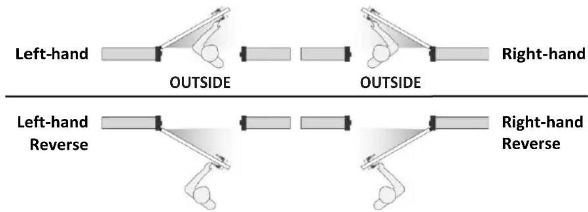
Determine whether the door is left-hand (LH), right-hand (RH), left-hand reverse (LHR) or right-hand reverse (RHR) by referring to Figure 1.
Figure 1
INSTALLATION PREPARATION
Required Tools For Installation:
- Level
• #2 Phillips Head "Stubby" Screwdriver
• #3 Phillips Screwdriver - Center Punch
- 1" Hole Saw
- 3/8" Box End Wrench
- Hacksaw
- File
- 6" Scale
- Tape Measure
• Electric Drill Motor - Drill Bit Set
- Rubber Mallet
- Vise
- Hex Key Set
- Small Pick
- Ruler
- Torque Wrench
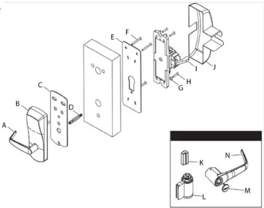
dormakaba PowerPlex P2000
A. Outside Lever Handle
B. Outside Housing
C. Gasket (when required)
D. Spindle(s)
E. Inside Adaptor Plate
F. Mounting Screws 12-24 1/8" Hex (3)
G. Flat Washer 12 OD (2 or 4)
H. Pan Head Screws 10-24 34'' (4)
I. Chassis
J. Inside Chassis Cover
K. Cylinder Plug
L. Cylinder
M. Cylinder Cap
N. Outside Lever Handle
Figure 2
Dorma F9300 Fire Rated Exit Device
Figure 3
 | Push Bar | ||
 | (4) #12-24 x 1" R.H.P.M.S. (Metal or Thru Bolts)(4) #12 x 1-1/4" R.H.P.T.S. (Wood Door) | Chassis and Mounting Screws | |
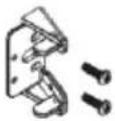 | (2) #12-24 x 1" R.H.P.M.S. (Metal or Thru Bolts) | End Cap Bracket and Screws | |
 | (2) #8-32 x 3/8" F.H.P.M.S | End Cap and Screws | |
 | (2) #10-32 x 5/8" F.H.P.M.S. (Metal)(2) #10 x 1" F.H.P.T.S. (Wood Door) | Strike and Screws | |
Parts
• R.H.P.M.S: Round Head Phillips Machine Screw
• R.H.P.T.S: Round Head Partial Thread Screw
• R.H.P.M.S: Round Head Phillips Machine Screw
• F.H.P.M.S: Flat Head Phillips Machine Screw
• F.H.P.T.S: Flat Head Partial Thread Screw
Covers and Other Parts:
• Universal Chassis Cover (515030)
• RHR Lock Cover (515031)
• LHR Lock Cover (515032)
• End Cap (515038)
• Retainer Clip (515041)
• Cable Connector Rod End (515040) (LHR - Short)
• Cable Connector Rod End (515029) (RHR - Long)
• Cable Assembly (115036)
• Hex Nut, Brass (115123)
- Lock Cover Bracket (515034)
Reference:
• Lever Knob Cam (515027) (LHR-Short)
• Lubricant (9810004) (not shown)
• Rod Connector and Cable Assembly (514033) (RHR-Long)
• Retainer Clip (515041)
• Cable Connector Rod End (515040) (LHR-Short)
• Cable Connector Rod End (515029) (RHR- Long)
• Brass Hex Nut, Brass (115123)
• Cable Assembly (116036)
• Cable Connector Rod End (515027) (RHR-Short)
Figure 4

CDX-10 High Security Lock:
- Mounting Plates
- DKX-10 Lock Body and Baseplate
- Spindle
- Dial Assembly
- Installation Instructions
- Installation Kit
- Backing Plate
- Hub
- Screw Kit
-
2 Strike
- Escutcheon Plate
Figure 5

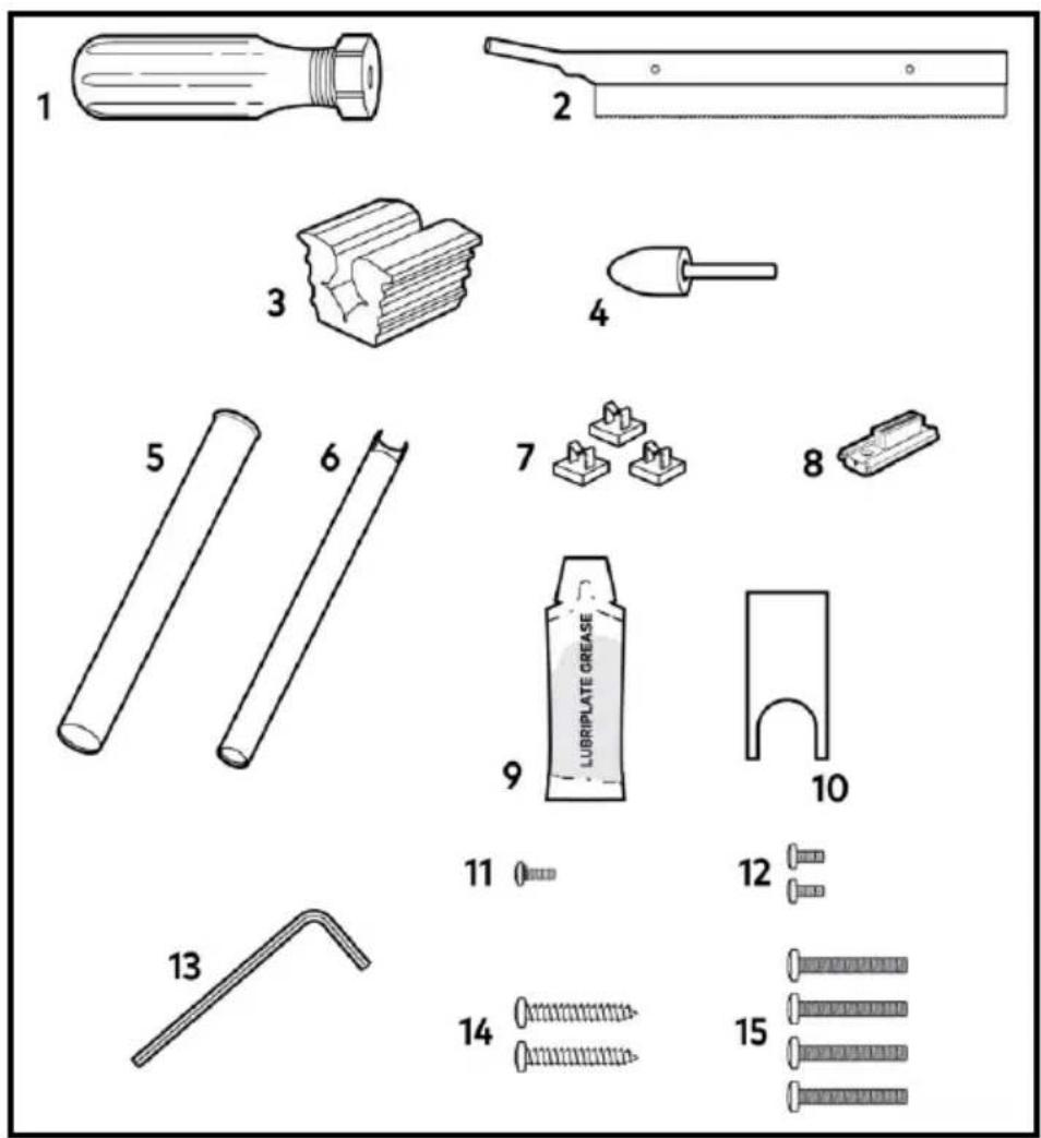
Kit Contents
- Saw Handle
- Saw Blade (52 teeth/inch)
- Vise Clamp
- Tube Deburr Stone
- Outer Tube
- Inner Tube
- Stick-on Cable Guides (3)
- Zebra Connector and Housing
-
Lubricant
-
Dial-Hub Locating Gauge
-
Spindle 6-32 Screw
-
Dial Ring to Exterior Mounting Plate Mounting Screws, Pan Head #8-32 x 5/16" (2)
-
Hex Key
-
CDX-10 Stabilizing Screws, Pan Head #10 x 1.25", Type AB (2)
-
CDX-10 Exterior Mounting Plate Attaching Screws, Pan Head #10-32 x 1.25" (4) (For thicker doors, you may need to use longer 10-32 pan head screws.)
Figure 6
INSTALLATION (Phase One)
dormakaba PowerPlex P2000
A. Use the template and mark the desired handle height on the edge of the door. (See Figure 7.) Note: Recommended centerline is 40^5 / 16" .
B. Use the template and mark a 2^-3/8 " backset vertical line (or the appropriate backset for your installation). Mark a horizontal line 40^5/16 " above the floor.
C. Position the template on the inside of the door aligning the door handle height mark and backset vertical line mark with the lines on the template. Use masking tape to secure the template to the door. Mark the position of the holes on the door. Remove template.
D. Using a ^3/_16 " drill bit, drill the pilot holes to the appropriate depth as indicated on the template.
E. Enlarge the pilot holes to the size that is indicated on the template. Note: It is recommended that you drill from both sides of the door to eliminate the possibility of splintering.
Note: Drill the holes in the door required for the exit device as indicated on the template.
Figure 7
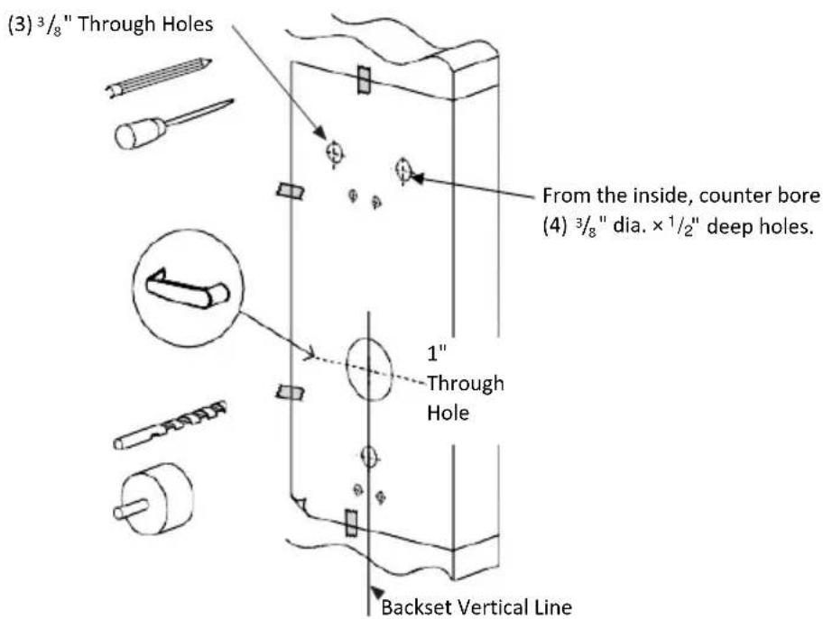
Figure 8
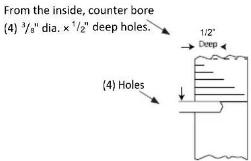
F. Install the Outside Lever of dormakaba PowerPlex P2000.
Figure 9

A. Assemble the lever on the outside housing, in the horizontal rest position appropriate to the handing of the door as shown. Simply push the lever onto the tube until it clicks in place. If more force is required to engage the handle, use a rubber mallet. Test the setting of the handle by pulling on it.
B. Use the ^5/_32 " hex key, tighten the set screw while pushing the lever against the plastic washer to remove the lever play.
C. The lever is reversible. If the handing is incorrect, insert a small pick or flat screwdriver in the hole in the hub as shown. Gently pry back the spring clip inside the hub and remove the handle.
Install Optional K-I-L or BEST Removable Core Override and Outside Lever
Upon unpacking, the lock housing with mechanical override should look like the diagram below with:
- The small indents (i) on the cross of the override shaft (m) in-line horizontally
• The plastic washer (c) on the drive tube
• The lever catch (f) in the out position
• Cylinder (j) and 2 keys (n) (included in the hardware bag) - Shaft override tool (o) (included in the hardware bag)
A. Push in the lever catch (f) firmly.
B. Insert the cylinder (j) into the lever handle (h).
Figure 10

Note: When using BEST Interchangeable cores, use steps below.
Figure 11
For BEST Removable Core
A. Insert 6-pin BEST adapter (thicker) into 6-pin interchangeable core or insert 7-pin BEST adapter (thinner) into 7-pin interchangeable core. Insert the adapter until it makes contact with the removable core.
B. Use the control key and assemble the removable core with its adapter into the lever. Remove control key.
C. Insert the change key into the removable core.

For Optional K-I-L Key
A. Put the cylinder plug (k) into the lever (h).
B. Ensure that the cylinder plug (k) does not fall out, insert the key into the cylinder (j). (The key will be horizontal.)

Figure 12
Caution: The position of the key is very important. If the lever is not assembled with the key in the correct position before placing the lever on the housing, the inside mechanism of the lock could be damaged if the lever is rotated and forced.
C. For Right-handed Levers: Turn the key clockwise until it stops so that it is in the vertical position and the countersink (g) is in the top position.
For Left-handed Levers: Turn the key clockwise until it stops so that it is in the vertical position and the countersink (g) is in the bottom position.
D. Fit the lever handle (h) onto the drive tube. It should rest approximately 1/16'' (2mm) from the body of the housing. If it can't be pushed that close to the housing, the lever catch (f) is probably not pushed in. Push it in. If the lever catch (f) is stuck, the override shaft is in the wrong position. The two small indents on the cross of the override shaft must be vertically aligned.
E. Press the lever firmly against the housing while turning the key counterclockwise (This applies to both right-handed and left-handed locks.) until it is in the horizontal position.
Important: If it is not possible to turn the key counterclockwise to complete this step, the spring washer (d) may be too tense. Tap the lever carefully with a rubber mallet to loosen the spring washer (l). Cover the lever handle with a cloth or other material to protect the finish of the metal.


Figure 13
F. Remove the key. (The lock will look as shown at right.)
G. Gently check the rotation of the lever handle. (It should easily rotate approximately 45^ .)
Troubleshooting: If you have assembled the lever and housing with the key in the wrong position, the key will get stuck. To remove the key, turn it so that it is in the vertical position and insert a small flat screwdriver into the hole under the lever handle to push the lever catch in (f). Remove key. If it is still stuck, turn the key clockwise until it stops to the horizontal position and push the lever catch in again with the small screwdriver. Remove key.
Right-Handed lock
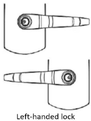
Figure 14
Troubleshooting:
Right-handed Lock: Turn the lever handle clockwise without forcing it. If it stops at approximately 15°, it was not assembled correctly. Do not try to force it to turn—this will damage the inside mechanism of the lock. Release the lever handle. Insert the small screwdriver into the small hole on the underside of the lever handle and push in the lever catch.
Re-do steps A-C in Phase One/Section E- Install the Outside Lever of dormakaba PowerPlex P2000.
Left-handed Lock: Turn the lever handle counterclockwise without forcing. The drive hub should not rotate when the lever handle is turned. If it does, it was not assembled correctly. Release the lever handle. Insert the small screwdriver into the small hole on the underside of the lever handle and push in the lever catch.
Re-do steps A-C in Phase One/Section E- Install the Outside Lever of dormakaba PowerPlex P2000.
H. Use the ^5/_32 " hex key and tighten the set screw while pushing the lever against the plastic washer to remove the lever play.
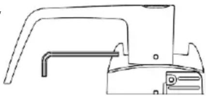
natural_image
Technical line drawing of a mechanical component or bracket (no text or symbols)Figure 15
Test the Operation of the Outside Lever
Verify that the lever has been correctly attached to the housing:
A. Remove key.
B. Insert a small flat screwdriver into the hole on the underside of the lever handle and push in the lever catch.
C. Pull on the lever.
(You should not be able to remove the lever. If the lever comes off of the housing, the lock is not assembled correctly. Re-do steps A-C in Phase One/Section E- Install the Outside Lever of dormakaba PowerPlex P2000.)
Test the Movement of the Lever (without the key in cylinder):
A. Turn the lever (h) clockwise for a right-handed lock or counterclockwise for a left-handed lock.
B. Release the lever slowly. It should return freely to its horizontal position.

Figure 16
Test the Mechanical Key Override with Change Key
Important: The key override itself does not retract the latch or deadbolt. Do not use too much force when turning the key as this may damage the unit. To retract the latch, turn the key clockwise until it stops, release the key and turn the lever.
Note: The lever must stay in the horizontal position when turning the key (Do not try to turn the key while turning the lever.) or the override mechanism will not work.
A. Without using the key, turn the lever clockwise for right-handed locks or counterclockwise for left-handed locks. The inside drive hub should not rotate when the lever turns.
B. With the lever (h) in the horizontal position, insert the key (n) into the cylinder and turn it clockwise until it stops. (This applies to both right and left-handed locks.)
C. Let go of the key, and again turn the lever handle (h) clockwise for right-handed locks or counterclockwise for left-handed locks. Now the inside drive hub (b) should rotate in the same direction as the lever handle when it is turned.


Figure 17
D. Install cap (i) to cover keyhole. The cap has a small groove on one edge to allow ease of removal. This should be facing down. Insert bottom snap of cap in lever hole below the cylinder. With a small screwdriver, push top snap of cap down while pushing the cap into place.
E. To remove the cap (i), insert a small flat screwdriver into this groove and gently pry the cap off, being careful not to damage it. Cover the bottom of the lever to protect the finish from being scratched through the process of removing the cap.

Figure 18
Change Key-in-Lever Lock Cylinders
A. Loosen the set screw to free the lever. (just 14 to 12 turn)
B. Remove the cap from the outside lever (h).
C. Insert key (n).
D. Turn the key clockwise until it stops.
E. Release key (n).
F. Use a small flat screwdriver to push in the lever catch through the small hole underneath the outside lever.
G. Pull the outside lever (h) off of the lock housing. (Be careful not to lose the cylinder plug (k). If it is difficult to pull the lever, slightly tighten or loosen the set screw.)
H. Replace the old cylinder with the new one in the lever handle. (Only the same kind of cylinder with 2 grooves in cross in the end of the cylinder plug can be used on the lock.)
I. Re-insert the cylinder plug (k).
J. Hold the cylinder (j) and plug (k) in place, insert the key.
Follow steps For K-I-L Key C to H and test as per Test the Operation of the Outside Lever, and Test the Mechanical Key Override with Change Key instructions.

natural_image
Technical line drawing of a mechanical component or bracket (no text or symbols)
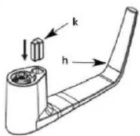
Figure 19
Change BEST-Type Core
A. Use the control key to remove the removable core from the lever.
B. Remove the adapter from the removable core and reassemble it on the new removable core.
Note: It is important that the new removable core has the same number of pins (6 or 7) as the dismounted one. If not, change the adapter to fit the core.
C. Check to make sure that the override shaft did not move and that the 2 small indents on override shaft are still vertical. (See Figure 21.) Then using the control key on the new core, assemble the new removable core on the lever.
D. Test the locks as per Test the Operation of the Outside Lever, and Test the Mechanical Key Override with Change Key instructions on pages 17-18.
Remove and Reassemble the Outside Lever
A. Loosen the set screw to free the lever lever. (just 14 to 12 turn)
B. Insert the change key in the cylinder.
C. Turn the key clockwise until it stops. (for both right and left-hand locks)
D. Release the key.
E. Use a small flat screwdriver to push in the lever catch through the small hole underneath the outside lever.
F. Pull the outside lever off of the lock housing. Be careful not to lose the adapter.
Important: Assemble the lever, cylinder and lock components before affixing the entire unit to the door.

natural_image
Technical line drawing of a mechanical component or bracket (no text or symbols)Figure 20
G. Ensure that the two small indents on the cross are now vertically in-line. (The cylinder or override shaft tool can be used to turn override shaft.)
H. Push in the lever catch (f) firmly .
2 Indents Vertical

flowchart
graph TD
    A["Top Circular Component"] --> B["Center"]
    C["Top Circular Component"] --> B
    D["Top Circular Component"] --> B
    E["Bottom Circular Component"] --> B
    F["Bottom Circular Component"] --> B
    G["Bottom Circular Component"] --> B
    H["Bottom Circular Component"] --> B
    I["Bottom Circular Component"] --> B
    J["Bottom Circular Component"] --> B
    K["Bottom Circular Component"] --> B
    L["Bottom Circular Component"] --> B
    M["Bottom Circular Component"] --> B
    N["Bottom Circular Component"] --> B
    O["Bottom Circular Component"] --> B
    P["Bottom Circular Component"] --> B
    Q["Bottom Circular Component"] --> B
    R["Bottom Circular Component"] --> B
    S["Bottom Circular Component"] --> B
    T["Bottom Circular Component"] --> B
    U["Bottom Circular Component"] --> B
    V["Bottom Circular Component"] --> B
    W["Bottom Circular Component"] --> B
    X["Bottom Circular Component"] --> B
    Y["Bottom Circular Component"] --> B
    Z["Bottom Circular Component"] --> B
    AA["Bottom Circular Component"] --> B
    AB["Bottom Circular Component"] --> B
    AC["Bottom Circular Component"] --> B
    AD["Bottom Circular Component"] --> B
    AE["Bottom Circular Component"] --> B
    AF["Bottom Circular Component"] --> B
    AG["Bottom Circular Component"] --> B
    AH["Bottom Circular Component"] --> B
    AI["Bottom Circular Component"] --> B
    AJ["Bottom Circular Component"] --> B
    AK["Bottom Circular Component"] --> B
    AL["Bottom Circular Component"] --> B
    AM["Bottom Circular Component"] --> B
    AN["Bottom Circular Component"] --> B
    AO["Bottom Circular Component"] --> B
    AP["Bottom Circular Component"] --> B
    AQ["Bottom Circular Component"] --> B
    AR["Bottom Circular Component"] --> B
    AS["Bottom Circular Component"] --> B
    AT["Bottom Circular Component"] --> B
    AU["Bottom Circular Component"] --> B
    AV["Bottom Circular Component"] --> B
    AW["Bottom Circular Component"] --> B
    AX["Bottom Circular Component"] --> B
    AY["Top Circular Component"] --> AZ["Arrow to Center"]
    AZ --> BA["Arrow to Right"]
    BA --> BB["f"]
Figure 21
Testing the Operation of the Lock
A. Rotate inside lever and hold. Ensure that the latch is fully retracted and flush with the latch faceplate.
B. Release the inside lever. The latch should be fully extended.
C. For dormakaba PowerPlex P2000, you need to activate the outside lever 3 to 4 times to power the lock prior to entering the combination.
D. Enter the factory set combination: 1,2,3,4,5,6,7,8. You should see a green light and hear a high-pitched tone as you push each button. When the lock opens, you will briefly hear the sound of an electronic motor.
E. Rotate outside lever and hold. Ensure that the latch is fully retracted and flush with the latch faceplate.
F. Release the outside lever. The latch should be fully extended. When the lock re-locks, you will again hear the motor.
G. If your product is an E24xx, you will have to generate an access code using the web application to test the lock operation.
H. With the door open, verify functionality of the mechanical key override as detailed in Install Optional K-I-L or BEST Removeable Core Override and Outside Lever.
INSTALLATION (Phase Two)
Dorma F9300 Fire Rated Exit Device
Figure 1

A. Choose the required spindle depending on the door thickness.
B. Remove the template. Mark the door to denote the lock and strike horizontal line.
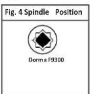
C. Insert the slotted end of the spindle (D) into the outside housing until it locks, at the correct position for the exit device. The spindle can be removed by pulling on it, and re-inserted if oriented incorrectly.
D. Place the outside housing (B) on the door. (for exterior use use the gasket (C) if required)
E. Attach adaptor plate (E) to the lock (B) using flat head screws (F)(12-24nc).
F. Attach the exit device chassis (G) to the adaptor plate (E) 4 screws (H).
G. Make sure the lock and the exit device chassis are well aligned and then tighten screws.
Figure 2
Install Strike
Figure 3

Note: Prepare to install panic bar and rail on door.
Note: All dimensions are based on 58 " stop height. Verify strikes, stile width, any trim, and stop height prior to making any cuts. If cutting is required, follow instructions below.
Figure 4
Fits 36" door opening without cutting.

Warning: If door is cut to 34" or less, covers may interfere with strike. Additional adjustments may be required for desired/adequate clearance.
Install Panic Bar and Rail Assembly to Door
A. Remove two 8-32 screws from chassis.
B. Loosen screws securing chassis and slide panic bar and rail assembly under rear of chassis.
C. Secure chassis mounting screws.
D. Remove protective covering from the panic bar and rail assembly prior to installing on door.
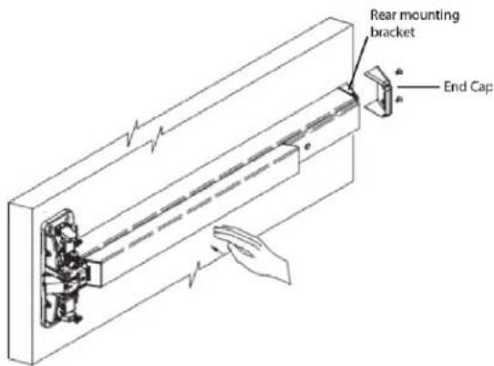
E. Hold rear mounting bracket tightly against door and rear of rail.
F. Assure panic bar is level.
G. Mark (2) holes and drill.
H. Secure with proper fasteners.
Figure 5

Install End Cap
A. Attach end cap with (2) screws
Figure 6
General Maintenance Notes
The dormakaba DKX Series Exit Devices are designed to give years of trouble-free service, however, depending on installation, location, climate conditions, etc., routine maintenance is recommended in all latch bolt locations. The device should be periodically cleaned and re-lubricated with Dura-Lube or equivalent to ensure proper function of all moving parts.
INSTALLATION (Phase Three)
Install DKX-10/DKX-19 Lock Strike
Note: It is recommended to install the DKX Series Strike (Type 2) first, followed by the lock installation.
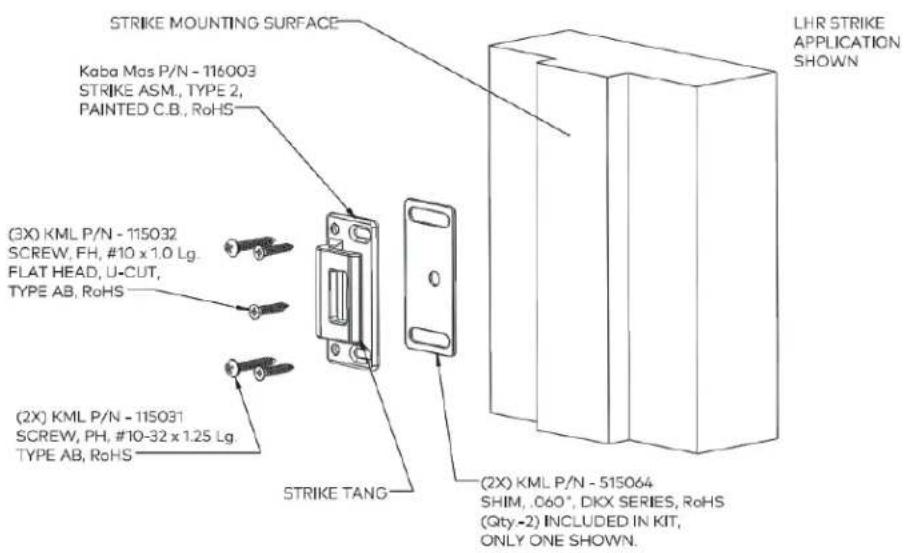
A. Locate the strike horizontal centerline off the lock horizontal centerline, and mark a horizontal line on the strike mounting surface.
B. Position the strike edge, 1/8" (.12") away from the face of the door while flat against the strike mounting surface (See Figure 1.) centered on the horizontal centerline. The Qty.-2 Shims (515064) can be used for the (.12") spacing, they are each .060" thick, two is (.12").
C. Mark lines, and/or scribe the centers of the two slotted hole locations, mid-slot.
D. Now punch this center in preparation for drilling.
E. Drill and tap the two slotted hole locations for attaching screws. (No. 25 drill, .149" diameter for the #10 thread forming screws. No. #21 drill, .159" dia. for the #10 machine screws)
Figure 1
DKX-10/DKX-19 High Security Lock Installation
The DKX-19 base plate installation is identical to the DKX-10 base plate installation. Refer to the included S\~G 2740B lock installation instructions. The S\~G 2740B installation instructions are included with the lock.
Warning: The electronics in the DKX-10 are susceptible to damage from Electro-Static Discharge (ESD). Ensure proper grounding.
Figure 2

A. Place the 3.5" x 5 x 1/8" backing plate against the back of the DKX Series lock case assembly.
B. Feed the cables and outer tube through the 0.5" hole in the door while positioning the DKX-10, backing plate, and cover bracket (515034), oriented correctly as shown in above illustration, against the door.
C. Insert and slightly tighten two of the #10-32 machine screws (115052) (top and bottom, diagonal) to attach the CDX-10, backing plate and cover bracket (515034) to the door.
Figure 3

Helpful Hint: If available, another inner tube inserted from the dial ring side, with the cables carefully fed through it, can be very helpful as a guide in feeding the cables through the door face.
D. Locate the lock assembly and install the two remaining machine screws (115052).
E. With all four machine screws in place, and the lock assembly located correctly, tighten all four screws.
F. Once the lock is correctly positioned and secured, install the two remaining mounting screws (Sheet Metal/Wood_115031) nearest the strike opening (top and bottom) to attach the CDX-10 assembly to the door panel.
Cut the Tubes
Warning: The end of the large tube that is to be discarded must be from the plain (un-flared) end of the tube. The end of the small tube that is to be discarded must also be from the plain (un-notched) end of the tube.
A. Make sure that the outer tube is properly placed over the lock case tube retainer.
B. Hold the outer tube firmly in its seated position and use a 6" scale or ruler to measure 516 " from the door face and mark the outer tube at this length.
C. Remove the lock case assembly from the door and remove the outer tube for cutting.
D. Assemble the saw blade and wooden saw handle provided. (To assemble the saw, grip the saw frame in a vise, just below the neck. Drive the handle fully onto the neck. This will reduce the tendency of the handle to turn on the saw frame when sawing.)
Note: This saw is intended only for cutting the tubes. A standard hacksaw should be used to cut the spindle.
Warning: The end of the outer tube that is to be discarded must be from the plain (unflared) end of the tube. The end of the inner tube that is to be discarded must also be from the plain (un-notched) end of the tube.
DKX-10/DKX-19 High Security Lock Installation (Continued)
G. Place the inner tube into the lock case tube retainer. (Ensure that the cutout in the tube aligns with the cables and allows the tube to seat completely in the tube retainer.)
H. Refer to Figure 4. Feed the cables through the outer, larger, tube starting from the flared end of the tube.
I. Seat the tube into position on the tube retainer on the back of the lock case assembly. (Be careful to keep the cables pulled taut while seating the tube to avoid pinching damage to them.)
Alternate Method: Depending on the width of the door, it may be easier to insert the non-flared end of the outer tube through the spindle hole from the inside of the door and feed the cables through the tube, and then seat the flared end of the tube on the tube retainer.
Figure 4

Figure 5

natural_image
Close-up of a mechanical assembly with a metallic rod and metal bracket, no visible text or symbolsSeat Inner Tube in Retainer
Figure 6

J. Feed the cables and outer tube through the .500"-inch hole in the door while positioning the DKX-10 and backing plate against the door. Insert and tighten slightly two #10-32 screws nearest the strike opening (top and bottom) to attach the DKX-10 and backing plate to the door.
Helpful Hint: If available, another inner tube inserted from the dial ring side, with the cables carefully fed through it, can be very helpful as a guide in feeding the cables through the door face.
Install the Dial Ring
A. Remove the two screws from the dial ring assembly cover and remove the cover.
Note: Make sure the tubes are projecting through the door. If not, the tubes are not seated properly in the lock or they were not cut to the proper length. Correct the problem before proceeding.
B. If necessary, rotate the tube retainer in the dial ring so that the cables come through the notch in the tube retainer.
C. Feed the cables through the tube retainer on the dial ring assembly and place the dial ring assembly over the end of the tubes. Make sure the tubes are seated in the tube retainer on the dial ring assembly.
D. Attach the dial ring to the door with the dial ring mounting screws and tighten to the specified torque.
Install the Cables
A. Open the ZIF (Zero Insertion Force) seal cover and move the ZIF connector locking actuators outward to their open position.
B. Plug the cables into the ZIF connectors with the bright metal tabs on the cables facing toward the circuit board to which the ZIF connectors are mounted.
C. Push the cables into the connectors as far as they will go.
Figure 7
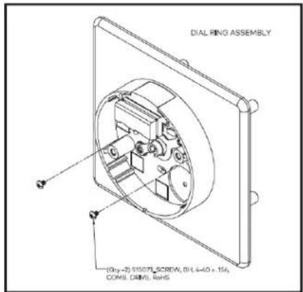
Figure 8

Closed and Open ZIF Connectors
Figure 9

ZIF Seal Cover (shown closed)
D. Close the ZIF locking actuators to lock the cables in place.
E. Close the seal cover and ensure the tenons in the seal cover align with the holes in the coordinating piece of the seal cover.
Figure 10
LCD and ZIF Connectors

Install Generator Cable and Cable Guides
A. Place the generator cable into the dial ring housing recess containing a post used for positioning the cable. The hole in the cable must be positioned over the post on the dial ring, and the five gold tabs must be exposed.
B. The Zebra connector and Zebra connector housing are assembled at the factory but may come apart during shipment. If so, insert the Zebra connector back into the Zebra connector housing before proceeding.
Caution: The Zebra connector is an electrical connector. Keep it clean!
C. Place the generator Zebra connector and connector housing assembly over the generator cable and press it into the recess. The hole in the Zebra connector housing must be positioned over the post in the dial ring. Be sure that the black Zebra connector housing is positioned so that grooves are facing towards you.
D. Install at least one of the stick-on cable guide in an appropriate position to restrain the cables.
E. Route the cables through the cable guide that was just installed.
F. Depending on the thickness of the door, additional cable guides may be necessary to ensure the cables are sufficiently restrained. Install additional guides as needed, and route the LCD and generator cables through them to ensure that the cables do not get routed through the "KEEP CLEAR" area, over the Zebra connector, or near where the geared end of the dial hub will project through the dial ring cover.
Figure 12
Cable Guide Locators

Figure 13
Dial Ring Cover
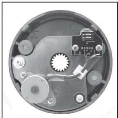
natural_image
Interior view of a circular mechanical device with visible gears and components (no text or symbols)Figure 11
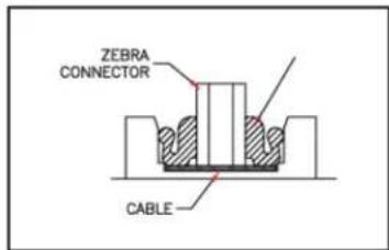
Zebra Assembly
Install the Dial Ring Cover
A. Align the dial ring cover with the dial ring so that the generator will seat into the five o'clock position and the four aligning lugs align with the corresponding slots in the dial ring.
B. Carefully slide the dial ring cover into the dial ring.
C. Hold the dial ring cover in place and tighten the two, dial ring cover mounting screws to the specified torque.
Install the Spindle
A. Install the spindle into the lock case. (The first resistance you feel when inserting the spindle is the spindle seal.)
B. Rotate the spindle until it drops into the cam. (The spindle is not fully seated until you feel the second drop.)
C. Install the spindle screw from the back of the lock. (It requires at least 8 turns of the screw to tighten the screw to the drive cam.)
D. Using the hub to hold the spindle in place, tighten the spindle screw.
Install the Dial Hub and Dial
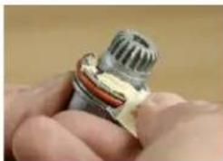
A. Apply a liberal amount of lubricant to the hub-bearing surface.
B. Slightly bend the dial hub-spacing gauge at its midpoint and slide it behind the dial hub.
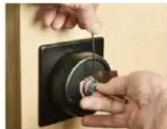
C. Pull out the spindle while pressing in on the dial hub with your thumb.
D. Snug the set screws while holding the dial hub in this position.
E. The proper set screw tension is 1" of deflection of the hex key.
Caution: Tighten in a downward motion in case the hex key should break.
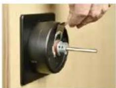
F. Remove the dial hub-spacing gauge.
G. Using the hacksaw cut the spindle flush with the dial hub. (It may be necessary to use a file to make the spindle flush with the hub.)
Caution: The spindle should not extend past the dial hub once installed but may be recessed up to 132 " below the surface of the hub. If it extends past the dial hub, it must be filed to flush.
H. Place a small amount of lube on the dial retaining ring in three spots around the dial hub and the center ring on the dial hub.
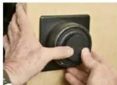
I. Press the dial firmly on the dial hub in the event it comes to a hard stop before it is seated, stop and realign the dial-retaining clip. (When it is fully seated, you should hear the dial retaining ring snap into the groove.)
Note: The dial should not be able to be pulled away from the dial hub assembly. The dial clutch should provide a slip torque of 7 to 25 inch-pounds.
J. Check the operation of the lock by verifying the following:
- Ensure that the dial turns freely without scraping or binding.
- Ensure that all screws have been securely tightened.
- Dial the combination. (It has been factory set to 50-LEFT, 25-RIGHT, 50-LEFT.) The lock should dial freely without scraping or rubbing and should open when the correct combination has been dialed.
Figure 14
natural_image
Close-up of a hand holding a metallic cylindrical device with a red and yellow patch (no visible text or symbols)Apply a liberal amount of lubricant to the hub-bearing surface.
Figure 15

natural_image
Close-up of a black mechanical component with a central shaft and mounting base (no visible text or symbols)Slightly bend the dial hub-spacing gauge at its midpoint and slide the spacing gauge behind the dial hub.
Figure 16
natural_image
Close-up of hands using a power switch to adjust a black circular component (no text or symbols visible)Pull out the spindle while pressing in on the dial hub with your thumb.
Figure 17

natural_image
Close-up of hands using a tool to adjust or install a mechanical component (no visible text or symbols)Snug the set screws while holding the dial hub in this position.
Figure 18
natural_image
Close-up of a hand using a tool to adjust or install a mechanical component (no visible text or symbols)Remove the dial hub- spacing gauge.
Figure 19

natural_image
Person using a red-handled tool to cut a black electrical component (no visible text or symbols)Using the hacksaw cut the spindle flush with the dial hub.
Figure 20

natural_image
Close-up of a mechanical component with a central metallic part and visible internal structure (no text or symbols)Place a small amount of lube on the dial-retaining ring in three spots around the dial hub and the center ring on the dial hub.
Figure 21
natural_image
Close-up of hands adjusting a black circular object with a ring (no visible text or symbols)Press the dial firmly on the dial hub.
Interface Hardware
Cable Assembly
These steps describe how to attach the rod end connector (515040 or 515029), Figures 23 and 24, and stainless-steel mechanical cable assembly (116036) to the lock and Rim Exit Device chassis. It also describes how to connect the cable assembly and adjusting the cable length to achieve proper timing of the high security lock bolt retraction relative to the rim exit device latch bolt.
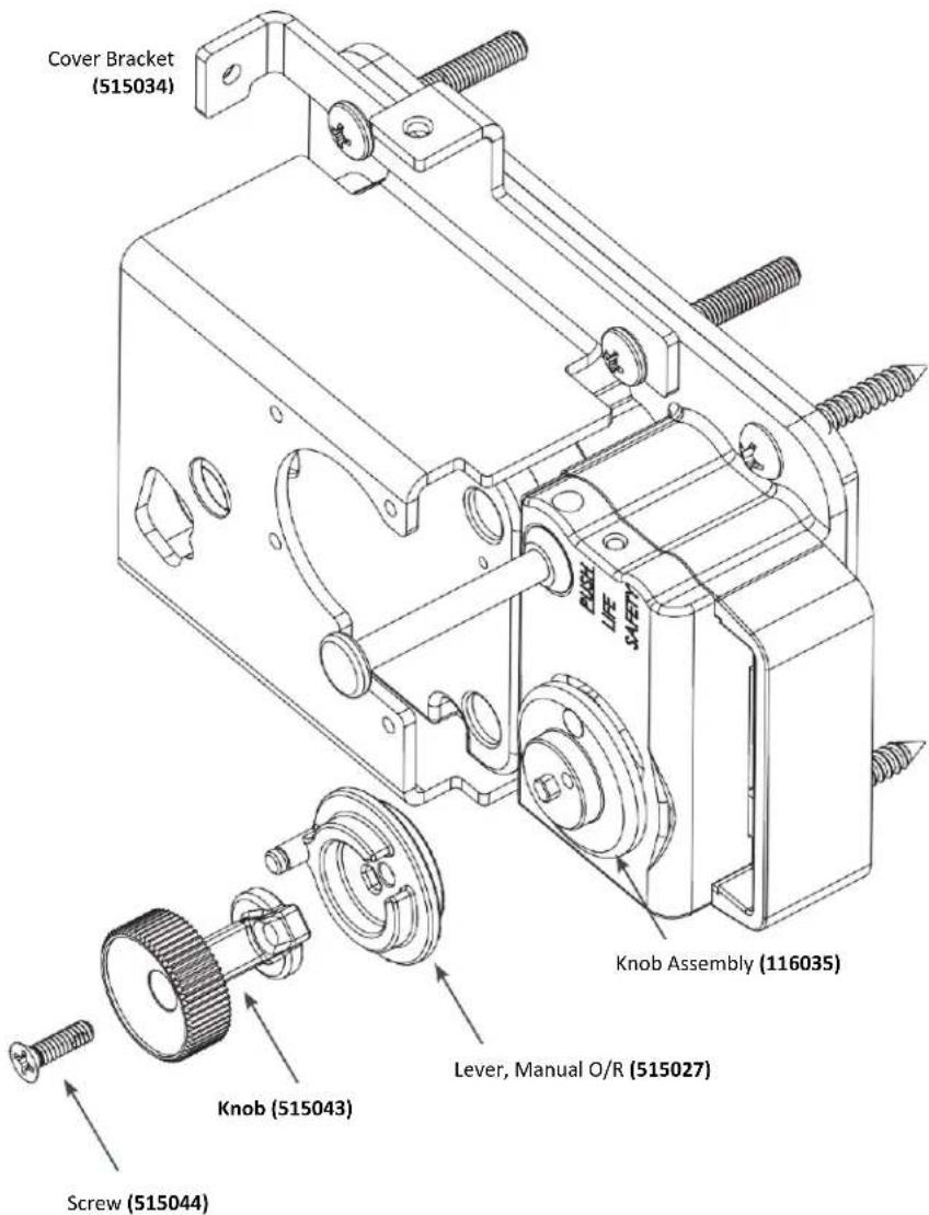
Install Knob Lever Assembly
A. Install the knob lever assembly once the lock assembly and the cover bracket (515034) are successfully installed.
B. Align the "Double D" hole in the knob lever (515027) with the "Double D" protrusion on the knob assembly (116035), and push the lever knob (515027) onto the knob assembly (116035).
C. Align the screw hole in the manual knob (515043) with the hole in the knob lever (515027), and hold into slotted position.
D. Place the knob assembly screw (515044) through the hole in the manual knob (515043) and tighten into position. Tighten to a minimum of 15 in.-lbs.
Figure 22
Install Lock Cable Assembly
A. Ensure correct assembly of the rod end connector (515040 or 515029), jamb nut (115123) and cable subassembly (116036).
Note: Do not tighten the jamb nut down on the connector rod until the optimum timing is achieved in opening the DKX-10 or DKX-19 high security lock.
B. Attach this subassembly to the cam lever (515027) with the retaining clip (515041).
C. Refer to Figure 23 or Figure 24 depending on the handing of the installation.
D. Use lubricant (9810004) to adequately grease all moving parts on both RHR and LHR cable/cam and levers. A generous application of grease is recommended.
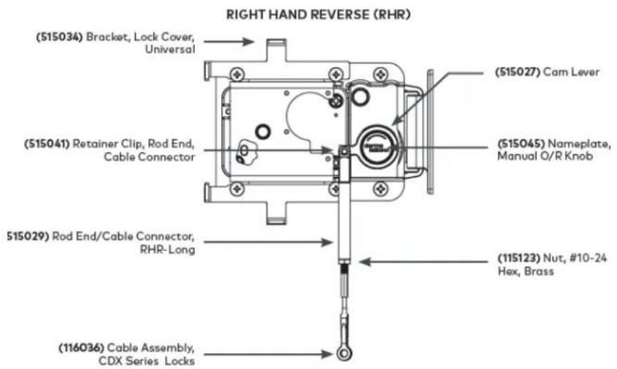
Figure 23
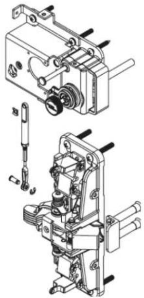
natural_image
Technical line drawing of a mechanical assembly with exploded and assembled views (no text or symbols)Figure 23 (RHR Application Shown)

Figure 24

natural_image
Technical line drawing of a mechanical assembly with exploded and assembled views (no text or symbols)Figure 24 (LHR Application Shown)
Install Cable Assembly
A. Locate the cable assembly (514040), which has a strap fork (Clevis) secured by a ball and shank on one end and a brass threaded (#10-24) plug with a brass nut (115123) on the other end.
B. Refer to Figure 23 or Figure 24 depending on the handing of the installation. Spread the (Clevis) strap fork over the upper lever arm (DK9300-020-520) of the Rim Exit Device chassis and align the strap fork holes with the hole in the (Clevis).
C. Secure the (Clevis) strap fork to the lever arm (DK9300-020-520) pivot pin (6400-127-400) and the "C"-Clip (337-110). When the correct timing is achieved, tighten the lock nut (115123) down on the connector rod (515040).
Connect Cable Assemblies
A. Refer to Figure 25 or Figure 26 depending on the handing of the installation. Move the brass jamb nut (115123) away from the open end of the brass threaded plug on the cable assembly (116036). Turn the brass-threaded plug into the turnbuckle on the lock cable assembly until approximately half of the threaded plug is inside the turnbuckle.
B. DO NOT tighten the brass nut on the threaded plug at this time.
Adjust Cable Length
The effective cable length may be changed by turning the brass-threaded plug into and out of the turnbuckle. The cable length must be adjusted so that as the panic bar of the Rim Exit Device is depressed, the DKX Series bolt is fully retracted and latched back just before the Rim Exit Device latch bolt clears its strike. Refer to Figure 25 and Figure 26 in preparation for adjusting the cable length. The proper sequence of adjustment is:

Figure 25-RHR
Figure 26-LHR
A. With the door open, slowly depress the panic bar and determine if the CDX-10 bolt retracts and latches back prior to maximum depression of the panic bar. If the bolt does not retract and latch back, slightly shorten cable and recheck.
B. Close the door and slowly depress the panic bar until the rim exit device latch bolt just clears its strike. Check to see if the CDX-10 bolt is fully retracted and latched back at this point.
If not fully retracted and latched back: Shorten the cable length until the CDX-10 bolt retracts and latches back just before the Rim Exit Device latch bolt clears its strike.
If fully retracted and latched back: With the door open, depress the panic bar until the CDX-10 bolt retracts and latches back. Depress the CDX-10 bolt reset latch to allow the CDX-10 bolt to extend. Check to see if the pulley restores clockwise sufficiently to prevent the CDX-10 bolt from being pushed back. (A thin-blade screwdriver may be inserted between the end of the bolt and the bolt guard for the purpose of pushing back on the bolt.) If the CDX-10 bolt can be pushed back, slightly increase the cable length and recheck the CDX-10 bolt latching status by following the directions above.
C. Finger tighten nut. Then using the wrench tighten down nut 1/8-1/4 turn max (30-40 in-lb). Do not exceed 50 in-lb, this may result in failure.
D. Adjust the CDX-10 strike so that the throat of the strike has minimum clearance of the bolt guard when the door is contacting the jamb.
E. Assure no load on the CDX-10 bolt, from the strike, (There should be no touching of the bolt against the strike.) mark and transfer punch the remaining (3) screw locations for the CDX-10 strike.
F. Install the remaining (3) screws. Ensure proper and correct function/location of both lock systems.
G. Ensure proper function of all lock systems before continuation of cover installation.
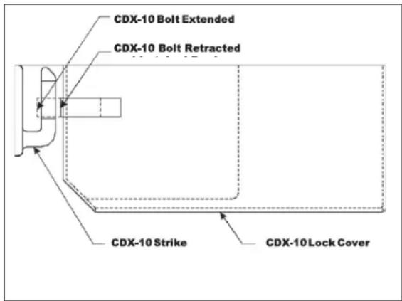
Figure 27- Position of CDX-10 Bolt Fully Retracted and Latched Back (Top View LHR Shown)
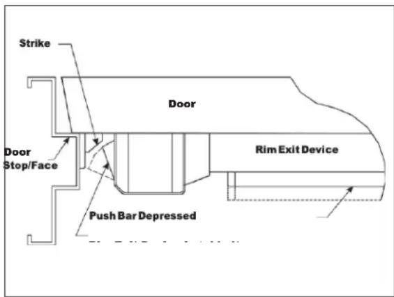
Figure 28 - Position of Latch bolt Just Prior to Clearing Strike (Top View LHR Shown)
Covers
Install Chassis Cover
A. Locate the universal chassis cover (515030) and end cap.
B. Orient the universal chassis cover, as it will be installed, based on door handing, and slide the end cap into the universal chassis cover.
C. Position the universal chassis cover over the Rim Exit Device, aligning the cover cutouts to fit over the chassis. Locate the cover flush to the surface of the door and bias the cover away from the door edge.
D. Secure the universal chassis cover to the Rim Exit Device using four (4) #8-32 x 5/16" PHMS (105034) screws.
Figure 29

Install Lock Cover
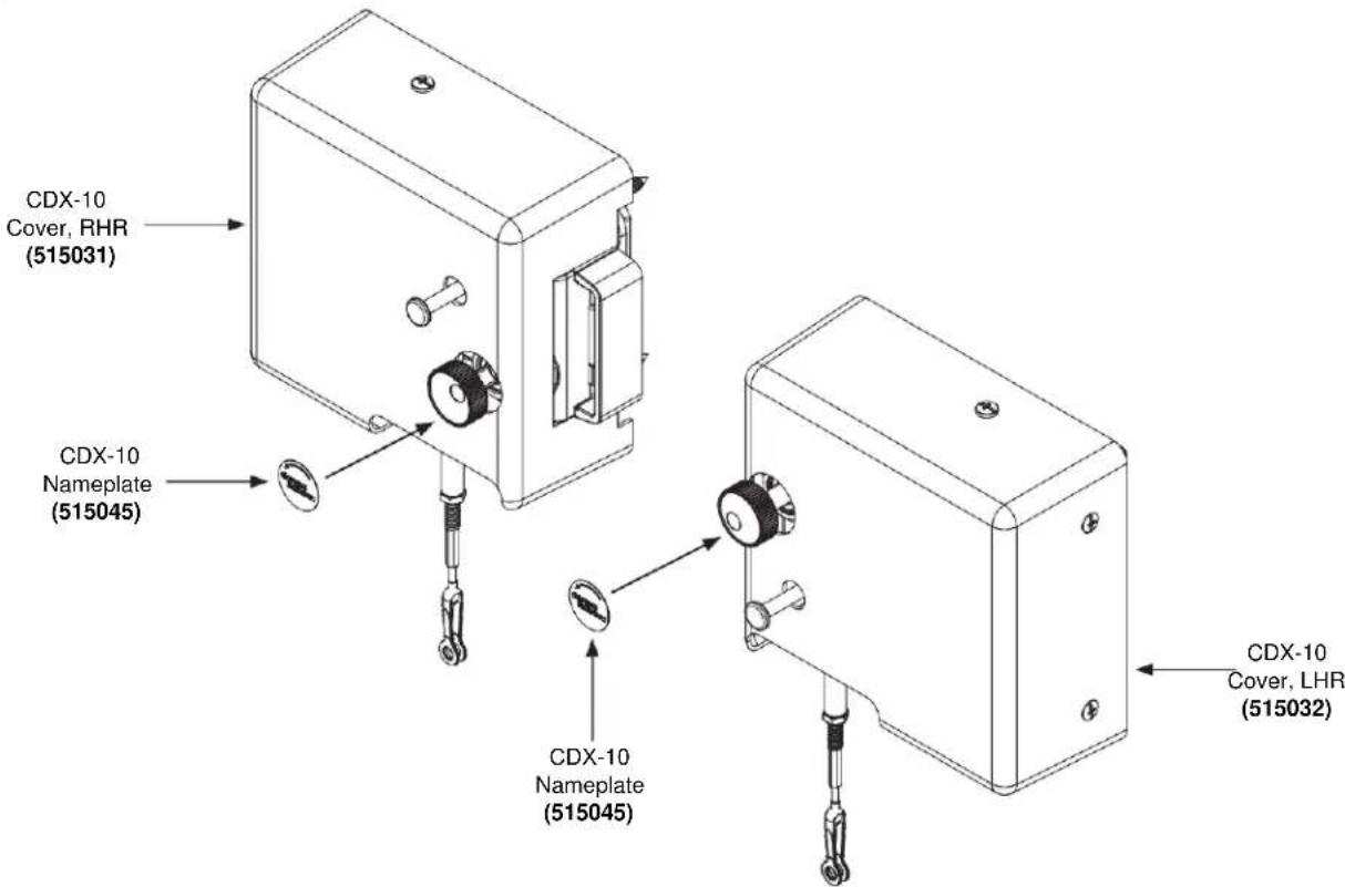
A. Locate the correct lock cover based on door handing. (See Figure 30.) (Both a RHR (515031) and a LHR (515032) lock cover are included in the Rim Exit Device box.)
B. Position the lock cover over the lock cover mounting brackets. Locate the cover flush to the surface of the door and bias the cover away from the door edge.
C. Secure the lock cover to the lock cover mounting brackets using four (4) #8-32 x ^5/16 " PHMS (105034) screws. (See Figure 30.)
Install Manual O/R Knob Label
Upon completion of the CDX-10 Lock and Exit Device installation, locate (515045) nameplate label. Remove paper backing, orient correctly, locate concentrically while applying pressure to adhere the label to the knob.
Figure 30
NOTES:
NOTES:
- Installation Instructions
- TABLE OF CONTENTS
- INTRODUCTION 4
- DETERMINE DOOR HANDING 6
- INSTALLATION PREPARATION....7
- PARTS CHECKLIST 8
- INSTALLATION (Phase One) 13
- INSTALLATION (Phase Two) 23
- INSTALLATION (Phase Three).... 26
- DKX-10/DKX-19 High Security Lock Installation (Continued) 28
- Covers 35
- INTRODUCTION
- Please read all directions carefully.
- Notes:
- DKX-10 TYPE III COMPONENTS
- DETERMINE DOOR HANDING
- INSTALLATION PREPARATION
- Required Tools For Installation:
- dormakaba PowerPlex P2000
- Dorma F9300 Fire Rated Exit Device
- Parts
- Covers and Other Parts:
- Reference:
- CDX-10 High Security Lock:
- Strike
- Kit Contents
- INSTALLATION (Phase One)
- Install Optional K-I-L or BEST Removable Core Override and Outside Lever
- For BEST Removable Core
- For Optional K-I-L Key
- Troubleshooting:
- Test the Operation of the Outside Lever
- Test the Movement of the Lever (without the key in cylinder):
- Test the Mechanical Key Override with Change Key
- Change Key-in-Lever Lock Cylinders
- Change BEST-Type Core
- Remove and Reassemble the Outside Lever
- Testing the Operation of the Lock
- INSTALLATION (Phase Two)
- Install Strike
- Install Panic Bar and Rail Assembly to Door
- Install End Cap
- General Maintenance Notes
- INSTALLATION (Phase Three)
- Install DKX-10/DKX-19 Lock Strike
- DKX-10/DKX-19 High Security Lock Installation
- Cut the Tubes
- DKX-10/DKX-19 High Security Lock Installation (Continued)
- Install the Dial Ring
- Install the Cables
- Install Generator Cable and Cable Guides
- Install the Dial Ring Cover
- Install the Spindle
- Install the Dial Hub and Dial
- Interface Hardware
- Cable Assembly
- Install Knob Lever Assembly
- Install Lock Cable Assembly
- Install Cable Assembly
- Connect Cable Assemblies
- Adjust Cable Length
- Covers
- Install Chassis Cover
- Install Lock Cover
- Install Manual O/R Knob Label
Brand : Dormakaba
Model : DKX Type III
Category : Access Control