DKX-10 Type II - Access Control Dormakaba - Free user manual and instructions
Find the device manual for free DKX-10 Type II Dormakaba in PDF.

| Product Type | Access Control Lever Release Lockset |
| Model | DKX-10 Type II |
| Brand | Dormakaba (formerly Kaba Mas) |
| Compatible Combination Locks | Kaba Mas X-10 (Style 1) or Sargent & Greenleaf 2740B (Style 2) |
| Cylindrical Lockset | Best 9K with Small Format Interchangeable Core (SFIC) |
| Door Thickness Compatibility | 1-3/4" to 2-1/4" (spacer available for 1-3/8") |
| Handing | Left Hand (LH), Right Hand (RH), Left Hand Reverse (LHR), Right Hand Reverse (RHR) |
| Backset Options | 2-3/4", 3-3/4", or 5" depending on door type and handing |
| Power Supply (Electrified Version) | 24 V AC or DC, 0.18 A continuous duty |
| Request-to-Exit (RQE) Switch | Integrated, rated 24 V AC/DC, 1 A max |
| ESD Protection | Protected to greater than 25,000 V when correctly installed |
| Dial Ring Cover | Includes generator cable and Zebra connector for power generation |
| Installation Tools Required | Measuring tape, level, various drill bits (1/8" to 2-1/8" hole saw), screwdrivers, hacksaw, file, hex key (5/64") |
| Maintenance | Periodic cleaning and lubrication with Dura-Lube or equivalent; cable adjustment if necessary |
| Warranty | Refer to manufacturer; typical commercial lock warranty applies |
| Included Components (DKX-10 Kit) | Modified CDX-10 extension plate with X-10 lock, spindle, dial assembly, strike kit, mounting screws, cable tie clips, lubricant, deburring stone, hex key |
| Included Components (DKX-19 Kit) | Modified CDX-10 extension plate with S&G 2740B lock, dial/spindle assembly, strike kit, lubrication, escutcheon plate, back plate |
| Safety Compliance | GSA approved (FF-L-2890B Type II); meets building, fire, and security codes |
| Cable Length Adjustment | Via brass threaded plug and turnbuckle; ensures bolt retraction just before latch clears strike |
Frequently Asked Questions - DKX-10 Type II Dormakaba
User questions about DKX-10 Type II Dormakaba
0 question about this device. Answer the ones you know or ask your own.
Ask a new question about this device
Download the instructions for your Access Control in PDF format for free! Find your manual DKX-10 Type II - Dormakaba and take your electronic device back in hand. On this page are published all the documents necessary for the use of your device. DKX-10 Type II by Dormakaba.
USER MANUAL DKX-10 Type II Dormakaba
Preliminary 04/03/19
WARNING:
The Kaba Mas X-10 used with the DKX-10 type II is protected from Electrostatic Discharge (ESD) damage once installed, but can be damaged during the installation process if proper precautions are not observed. Follow these precautions to avoid ESD damage when installing the lock:
- Do not touch the end of the flex cable if the ESD protective cover has been removed.
- For the best protection, use an ESD wrist band grounded to the lock during installation.
- The lock is protected to greater than 25,000 V when correctly installed.
NOTE:
The GSA approved Kaba Mas FF-L-2890B type II Lever Release Lockset is available for use with a Kaba Mas, Style 1, X-10 combination lock or a Sargent & Greenleaf (S&G) 2740B, Style 2 combination lock.
This document designates the Best 9K Cylindrical Lockset with a modified CDX-10 lock as: DKX-10 Type II.
This document also designates the Best 9K Cylindrical Lockset with a modified CDX base with the S&G 2740B lock as: DKX-19, Type II.
The DKX-10, Type II combines, through linkage, a Best 9K cylindrical lockset and a Kaba Mas CDX-10 baseplate. If the system is ordered with a Kaba Mas X-10, the X-10 is mounted to the baseplate. If the system is ordered with an S&G combination lock, the S&G lock is mounted to the CDX-10 baseplate. The procedure to mount the DKX unit to the door is the same whether the combination lock is an X-10 or an S&G 2740B lock. The process to install and set up the X-10 (once the CD base plate is mounted to the door) is the same as it would be for any X-10 or CDX-10 installation. The installation and setup for the S&G 2740B lock is also the same as it would be for any standard installation. A copy of the Kaba Mas X-10 installation instructions is provided when the device is ordered with an X-10. S&G's 2740B lock installation instructions are provided with the S&G lock when it is specified.
Only technicians who have successfully completed manufacturer certified training for FF-L 2740B combination locks should install the DKX-10 or the DKX-19.
NOTE: One set of instructions should be left with the building owner after devices have been installed.
Trademarks
The following items are trademarks or registered trademarks of Kaba Mas in the United States and/or other countries.
• PowerStar Technology
- DKX-10, X-10
Document Number 548.0418
Rev. A 09/18
Kaba Mas LLC
1051 Newtown Pike Ste. 150
Lexington, KY 40511 USA
Phone: 859-479-1329 FAX: 859-303-8993
Technical Support: 800-950-4744
Table of Contents
Introduction 5
Installation Overview
Door Handing 6
Templates 6
DKX Series Lock Mounting
Best Cylindrical Lockset 6
Mounting
Parts Check 7
Packaging
Box Contents
DKXL-10 Contents or Parts 8
Lock Parts for Installation
DKXL-10 Installation 8
Kit Contents (P/N 504002)
DKX-19 Contents or Parts 8
Lock Parts for Installation
DKX-19 Installation Kit Contents 8
(P/N 514044)
Door preparation 9
Mark Cylindrical Lockset and Strike Locations
Install the Best 9K Lever Set, 10
and Strike
Install DKX Series Lock Strike 12
High Security Pedestrian 12
Door Lock Installation (DKXLX0)
Cutting the Tubes 13
Installation of the Lock 14
Installation of the Dial Ring 15
Installation of the Cables 16
Installation of Generator Cable 16 and Cable Guides
Installation of the Dial Ring Cover 17
Cutting and Installing the Spindle 17
Installation of the Dial Hub 18 and Dial
Interface Hardware 19
(DKX-10 and DKX-19)
Cable Assemblies
Install Knob Lever Assembly 19
Install Lock Cable Assembly 20
Connect Cable Assembly 21
Adjust Cable Length 21
Install Chassis Cover 23
Install Lock Cover 23
Install Manual O/R Knob Label 24
Cover Install 24
Maintenance 24
Appendix A 25
Electrified Cylindrical Lock Wiring Instructions
Introduction
Installation Overview
The DKX-10 Lever Release consists of:
- A Cylindrical Lockset (Best 9K) prepped for Small Format Interchangeable core (less core). Other cylinder configurations available.
- A modified High Security Pedestrian Door Lock (CDX-10)
- Interface Hardware, Covers and Cover Brackets
NOTE: Open box, lay out all parts and verify prior to beginning installation.
The Installation Guide will describe the steps required to install each component of the DKX-10 Lever Release Lockset.
Before beginning installation, be certain to have the following tools readily available:
- Measuring tape
• Level and straight edge - Combination square
- Tape
- Hammer
- Center punch
• Electric hand drill - 1/8" drill bit
- 1/4" drill bit
- 9/32" drill bit
- 5/16" drill bit
- 3/8" drill bit
- 1/2" drill bit
-
16, #21, and #25 and 7/16" drill bits • 2 1/8" hole saw with 1/4" pilot
- 1" hole saw with 1/4" pilot
- Long nose pliers
• Pliers - Adjustable wrench
• 3/8" box-end wrench - Hacksaw
- File
- 1/4" or smaller slotted head .0. screwdriver
• #1 Phillips head screwdriver
• #3 Phillips head screwdriver
• #1 Phillips head stubby screwdriver - Safety glasses
Other tools which may be required:
• #10-24 Screw cutter
For a metal door installation, the following tools are needed:
- Tap handle
- #10-24 tap
- #10-32 tap
• #12 - 24 tap
Door Handing
Determine whether the door is left hand (LH), right hand (RH), left hand reverse (LHR) or right hand reverse (RHR) by referring to Figure 1.
NOTE: Installer must ensure that the door meets all building, fire and security code requirements prior to installing the DKX-10 Lever Release Lockset.

Figure 1 - Door Handing
Templates
DKX Series Lock Mounting
A template (#115057) is included to assist in laying out the hole locations for the DKX-10 lock assembly. This template is positioned on the inside of the door as described in the "DKX-10 Lock Assembly Template" section.
Best 9K Cylindrical Lockset Mounting
A template is included to assist laying out the hole locations for the Best 9K cylindrical lockset. For LH, RH, LH sound sealed and RH sound sealed doors a 2 34 " backset template is provided (T56091). For LHR and RHR door a 3 34 " backset template is provided (T56077). LHR sound sealed and RHR sound sealed doors should be drilled for a 5" backset and is also on template (T56077).
1 Parts check
Packaging
The DKX-10 Type II Lever Release Lockset is packaged as follows:
- Best 9K cylindrical lockset with associated parts and mounting hardware
- Interface Hardware, Cam Plate Assembly (LH & LHR Only) Covers and Cover Brackets with mounting hardware
- DKX Series Installation Instructions Kit and Drill Template
• A modified High Security Pedestrian Door Lock (CDX-10)
• A High Security Pedestrian Door Lock Base Plate with S&G Model 2740 B Combination Lock
Box Contents
CylindricoLockset | 1. Best 9K Cylindrical Lockseto (1) Exterior handle prepped for SFICo (1) Chassis with rose linero (1) Interior handleo (1) Latch bolto (1) Strike plateo (1) Fasteners kit• (2) Through bolts• (2) Strike plate mounting screws |
InterfaceHardware | 2. Mounting Plate Assemblyo (1) Mounting plate (514052)o (1) Slide plate assembly (514053) |
CoversLH InteHardw | 3. Covers & Misc. Partso (1) DKX-10 LH Cover (515087)(LH and LHR)o (1) DKX-10 RH Cover (515088)(RH and RHR orders only)o (1) Lever Set Cover (513078)o (1) Cover Bracket (515034)o (1) Cam Plate Assembly (514049)(LH and LHR orders only)o (1) Connecting Rod Assembly (514054) |
DKX-10 Contents or Parts
Lock Parts for Installation
- Mounting Plates
- Modified CDX-10 Extension Plate with an X-10 Combination Lock
- Spindle
- Dial Assembly
- Installation Instructions
- Installation Kit
- Back Plate
8.Hub - Screw Kit
- Strike Kit
- Escutcheon Plate
DKX-10 Installation Kit Contents
(P/N 504002)
- Blade, saw (52 teeth/inch)
- Handle, saw
- Tube, outer
- Tube, inner
- DKX -10 to door mounting screws, pan head #10 x 1.25, Type AB (6)
- Dial ring attaching locknuts, #8-32 (2). (Packaged with and used with exterior mounting plate)
- Rubber vise clamp
- Lubricant
- Gauge, dial hub locating
- Zebra Connector and Retainer
- Cable Tie Clips (3)
- Dial ring to door mounting screws, pan head #8 -32 X
1.0 Type AB (2). - Cover Lock Pin and Clip
- Stone, deburring
- Hex key (5/64")
DKX-19 Contents or Parts
Lock Parts for Installation
- Mounting Plates
- Modified CDX-10 Extension Plate with a S&G 2740b Combination Lock
- Dial/Spindle Assembly
- Install Kit
- Misc. Install Kits (3X)
- Strike Kit
- Lubrication
- Escutcheon Plate
- Back Plate
DKX-19 Installation Kit Contents
(P/N 514044)
- Blade, Saw (52 teeth/inch)
- Handle, Saw
- Rubber Vise Clamp
- Stone, Deburring
2 Door preparation
Mark Cylindrical Lockset and Strike Locations
NOTE: Door must be fitted and hung properly before proceeding.
NOTE: Most doors are equipped with rubber bumpers to dampen the closure. The door must remain in the same state in which it was prepped.
NOTE: The suggested distance from the finished floor surface to the Best 9K cylindrical lockset horizontal reference centerline is 38", and may be varied to meet application requirements. However, in no case should this distance be greater than 48" due to National Fire Protection Association code requirements.
Figure 2 is a reference for the two drill templates referenced in this instruction guide.
It is recommended that the installer scribe two horizontal centerlines 10" apart, on both the door and the strike mounting surface. The line be the locator for both locksets, and associated strikes.

Figure 2: Reference Combined Template
3 Install the Best 9K Lever set, trim and strike
NOTE: For outswing doors a 3 3/4 " backset and latch bolt must be used for the cylindrical lock to avoid interference. For outswing sound sealed doors a 5" backset and latch bolt must be used for the cylindrical lock to avoid interference.
- Position Template

- Fold the template and place in position on the high edge of the door bevel as shown.
- Mark the drill points.
2. Bore two holes and install latch
- Bore a 2 18 " diameter hole from both sides of the door, to the center of the door.
- Drill a 1" diameter hole from the edge of the door that intersects the 2 18 " hole.
- Mortise the door edge for the latch face
-
Install the latch and check the door swing. Latch tabs should project into the 2 1/8" diameter hole.
-
Install boring fixture and drill two 5/16" diameter holes

- Install the boring jig (KD303) onto the door and engage with latch tabs. Make sure the front edge of the jig is parallel with the door edge as shown.
- Drill two 516 " diameter holes halfway into the door.
- Turn the boring jig over and repeat steps one and two from the opposite side of the door.
NOTE: Optional Boring Picture.
4. Adjust lockset to door thickness

- Pull the rose locking pin and rotate the outside rose liner in or out until the proper door thickness groove on the through bolt stud lines up with the hub face as shown.
NOTE 1: Make sure the locking pin locks into the rose liner.
NOTE 2: Locksets will fit doors 1 34 " to 2 14 " thick. (A spacer is available for 1 38 " doors.) See the enlarged view for the correct rose adjustment for these thicknesses.
- Engage retractor in latch

- With the latch in place, install the chassis from the outside. Make sure the latch tabs engage the chassis frame and the latch tailpiece engages the retractor as shown.
- Install mounting plate and through bolts.

- Align the holes in the mounting plate with the holes prepared in the door.
- Install through-bolts through the mounting plate and door in the top and bottom holes as shown.
- Tighten the mounting plate onto the door with the through-bolts.
- Optional: With the mounting plate secured on the door, center punch and drill a pilot hole 1½" deep, center marked in the four remaining holes on the face of the mounting plate, for a #10 sheet metal/wood screw (115031).
7. Install sliding plate assembly
NOTE: If the system being installed is to have Request to Exit functionality refer to Appendix A for installation instructions at this time.
- Align the holes in the sliding plate assembly (514053) with the PEM Nut standoffs on the mounting plate (514052).
- Tighten the sliding plate assembly onto the standoffs.

NOTE: The hub face of the cylindrical lock should be between the two plates on the Sliding Plate Assembly as pictured below. If the hub face is closer to the door than the Guide Plate (515076) remove the cylindrical lock and unthread the outside rose liner as described in Step 4. If the hub face extends past the Sliding Plate (515077) remove the cylindrical lock and thread on the outside rose liner as also described in Step 4.

8. Assemble and install core

flowchart
graph TD
    A["7-pin core"] --> B["Spacer"]
    B --> C["HJ throw member"]
    C --> D["Control key in core"]
    B --> E["Throw member"]
    E --> F["HJ throw member"]
    style A fill:#f9f,stroke:#333
    style B fill:#ccf,stroke:#333
    style C fill:#cfc,stroke:#333
    style D fill:#fcc,stroke:#333
    style E fill:#cff,stroke:#333
    style F fill:#ffc,stroke:#333
For 6-pin core users only: Slide the spacer – supplied with your 6-pin cores – over the 7-pin throw member.
For 'H' or 'HJ' functions only: Install the proper throw member as shown above.
NOTE: If you have ordered 6-pin cores, you will get one spacer per core with your order. Spacers are not supplied with locks.
9. Install strike plate
- In alignment with the center of the latchbolt, mortise the door jamb to fit the strike box and strike plate.
CAUTION: The deadlocking plunger of the latchbolt must not enter the strike plate opening. The plunger deadlocks the latchbolt and prevents forcing the latch when the door is closed. A gap of more than 1/8" may reduce security and/or cause improper operation of the latchbolt.
- Insert the strike box and secure the strike with the screws provided as shown.

- Insert the throw member (or throw member and spacer) into the back of the core as shown.
- Put the control key into the core and turn the key 15 degrees clockwise.
- Put the core and throw member into the lever with the control key as shown.
- Turn the key 15 degrees counterclockwise and remove the key.
CAUTION: Since the control key is a high-security key, make sure to keep it protected.
NOTE: For the electrified 9K trim and RQE refer to Appendices A and B for wiring instructions.
4 Install DKX Series Lock Strike
NOTE: The DKX-10 Type II can be used with multiple types of doors. Reference Figure 3 as a guide to which strike is needed.
- Using the horizontal centerline that was scribed following the steps previously mentioned in this instruction guide mount the appropriate strike for the door type as shown in the figure above.
- Mount the provided drill template (115057) flush to the strike mounting surface and collinear with the previously scribed horizontal center line and transfer the center marks onto the door.
- Drill all holes according to the diameters listed on the template.
5 High Security Pedestrian Door Lock Installation
(DKX-10)
NOTE: Prior to continuing Deburr and clean all holes and debree.
WARNING: The electronics in the X-10 are susceptible to damage from Electro-Static Discharge (ESD). Ensure proper grounding.

-
Place the 3.5" x 5 x 1/8" backing plate against the back of the modified CDX-10.
-
Feed the cables and outer tube through the 3/8" hole in the door while positioning the DKX-10, backing plate, and Cover Bracket (515034), oriented correctly as shown in above illustration, against the door. Insert and slightly tighten two of the #10-32 machine screws (115052) (top and bottom, diagonal) to attach the DKX-10, backing plate and Cover Bracket (515034) to the door.
12 Document Number 548.0418 Rev. AX — 02/2019

Figure 3 - Tube-Cable Assembly Relationships
HELPFUL HINT: If available, another inner tube inserted from the dial ring side, with the cables carefully fed through it, can be very helpful as a guide in feeding the cables through the door.
- Upon locating the Lock Assembly correctly, install the two remaining machine Screws (115052). With all four machine screws in place, and the Lock assembly located correctly, tighten all four screws to keep the assembly in place.
- When sure the position of the lock is complete, install the two remaining mounting screws (Sheet Metal/Wood_115031) nearest the strike opening (top and bottom) to attach the DKX-10 assembly to the Door Panel.
6 Cutting the Tubes
WARNING: The end of the large tube that is to be discarded must be from the plain (un-flared) end of the tube. The end of the small tube that is to be discarded must also be from the plain (un-notched) end of the tube.
- Make sure that the outer tube is properly placed over the lock case tube retainer.
- While holding the outer tube firmly in its seated position, use a 6" scale or ruler to measure 510 " from the container wall and mark the outer tube at this length.
- Remove the outer tube for cutting.
- Assemble the saw blade and wooden saw handle provided. To assemble the saw, grip the saw frame in a vise, just below the neck. Drive the handle fully onto the neck. This will reduce the tendency of the handle to turn on the saw frame when sawing.
NOTE: This saw is intended only for cutting the tubes. A standard hacksaw should be used to cut the spindle.
- Insert the tube to be cut into the rubber vise clamp (provided), with the mark just beyond the clamp. Then firmly clamp the rubber vise clamp in a vise. Use the saw to cut the tube where marked. Be careful to keep the cut as straight as possible. Remember the saw only cuts when pushing. Trying to cut while pulling may pull the handle off of the saw blade.
- The inside and outside of the tubes must be deburred after cutting. Use the stone which is provided for this purpose. Make sure there are no sharp edges on either tube inside and outside so as not to damage the cables.
- Install the inner tube on the lock case. Feed the cables through the outer tube and install the outer tube on the lock case. Measure and mark the inner tube to be 1/16" to 1/8" longer than the outer tube. Remove the inner tube and cut by the same method as described in Step 5.
WARNING: The end of the outer tube that is to be discarded must be from the plain (un-flared) end of the tube. The end of the inner tube that is to be discarded must also be from the plain (un-notched) end of the tube.
7 Installation of the Lock
- Place the inner tube into the lock case tube retainer. Ensure that the cutout in the tube aligns with the cables and allows the tube to seat completely in the tube retainer.
- Refer to Figure 5. Feed the cables through the outer, larger, tube starting from the flared end of the tube. Seat the tube into position on the tube retainer on the back of the lock case assembly. Be careful to keep the cables pulled taut while seating the tube to avoid pinching damage to them.
ALTERNATE METHOD: Depending on the width of the door, it may be easier to insert the non-flared end of the outer tube through the spindle hole from the inside of the door and feed the cables through the tube, and then seat the flared end of the tube on the tube retainer.

Figure 4 - Inner and Outer Tubes

natural_image
Close-up of a mechanical setup with a metallic rod and curved wire attached to a dark surface (no visible text or symbols)Figure 5 - Seat Inner Tube in Retainer
HELPFUL HINT: If available, another inner tube inserted from the dial ring side, with the cables carefully fed through it, can be very helpful as a guide in feeding the cables through the door.

Figure 5 - Tube-Cable Assembly Relationships
8 Installation of the Dial Ring
- Remove the two screws from the dial ring assembly cover and remove the cover.
NOTE: Make sure the tubes are projecting through the door. If not, the tubes are not seated properly in the lock or they were not cut to the proper length. Correct the problem before proceeding.
- If necessary, rotate the tube retainer in the dial ring so that the cables come through the notch in the tube retainer.
- Feed the cables through the tube retainer on the dial ring assembly and place the dial ring assembly over the end of the tubes. Make sure the tubes are seated in the tube retainer on the dial ring assembly.
- Attach the dial ring to the door with the dial ring mounting screws and tighten to the specified torque.

9 Installation of the Cables
- Open the ZIF (Zero Insertion Force) seal cover and move the ZIF connector locking actuators outward to their open position.
- Plug the cables into the ZIF connectors with the bright metal tabs on the cables facing toward the circuit board to which the ZIF connectors are mounted. Push the cables into the connectors as far as they will go.


ZIF Seal Cover (shown closed) Closed & Open ZIF Connectors

natural_image
Close-up of hands holding a pen or tool, no visible text or symbolsAssemble Saw

natural_image
Close-up of a hand using a mechanical pressor to adjust or install a black vise (no visible text or symbols)Cut Tube Using Vise
-
Close the ZIF locking actuators to lock the cables in place.
-
Close the ZIF seal cover. When closing, be sure the tenons in the seal cover align with the holes in the coordinating piece of the seal cover.
LCD and ZIF connectors


natural_image
Close-up of hands holding a small object with a pen, no visible text or symbolsDeburr Tubes
10 Installation of Generator Cable and Cable Guides
- Place the generator cable into the dial ring housing recess containing a post used for positioning the cable. The hole in the
cable must be positioned over the post on the dial ring, and the five gold tabs must be exposed.
- The Zebra connector and Zebra connector housing are assembled at the factory but may come apart during shipment. If so, insert the Zebra connector back into the Zebra connector housing before proceeding.
CAUTION: The Zebra connector is an electrical connector. Keep it clean!
- Place the generator Zebra connector and connector housing assembly over the generator cable, and press it into the recess. The hole in the Zebra connector housing must be positioned over the post in the dial ring. Be sure that the black Zebra connector housing is positioned.
16 Document Number 548.0418 Rev. AX - 02/2019

Zebra Assembly
- Install at least one of the stick-on cable guides in an appropriate position to restrain the cables.
- Route the cables through the cable guide that was just installed.
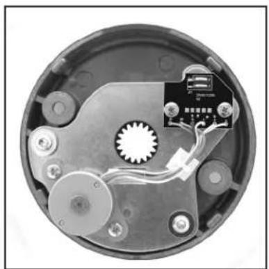
- Depending on the thickness of the door, additional cable guides may be necessary to ensure the cables are sufficiently restrained. Install additional guides as needed, and route the LCD and generator cables through them to ensure that the cables do not get routed through the "KEEP CLEAR" area, over the Zebra connector, or near where the geared end of the dial hub will project through the dial ring cover.

Cable Guide Locators
natural_image
Interior view of a circular electronic device with visible wiring and components (no text or symbols)Dial Ring Cover
11 Installation of the Dial Ring Cover
- Align the dial ring cover with the dial ring so that the generator will seat into the five o'clock position and the four aligning lugs align with the corresponding slots in the dial ring.
- Carefully slide the dial ring cover into the dial ring.
- Hold the dial ring cover in place and tighten the two dial ring cover mounting screws to the specified torque.
12 Cutting and Installing the Spindle
- Ensure that the lock bolt is extended and remove the cam from the lock case.
- Slide the dial hub onto the spindle, turning the hub slightly to align the generator drive gear teeth. Hold the drive cam assembly in place while installing the dial hub.
- Snug down one setscrew to hold the dial hub in place.
- Mark the spindle flush to the dial hub.
- Loosen the setscrew and remove the hub.
ALTERNATE METHOD: The hub may be left on instead of removed, and used as a vise to hold the spindle while cutting.
- Carefully cut the spindle so that it will be flush to the dial hub after installation.
CAUTION: The spindle should not extend past the dial hub once installed but may be recessed up to 1/32" below the surface of the hub. If it extends past the dial hub, it must be filed to flush.
- Remove all burrs from the end of the spindle.
13 Installation of the Dial Hub and Dial
- Apply lubricant to the hub bearing surface.
- While holding the drive cam and spindle in their proper positions in the lock case assembly inside the door, push the dial hub assembly onto the spindle.
- Make a bend in the dial hub locating gauge at its midpoint. This will keep it from acting as a spring as the hub is positioned for locking to the spindle.
- Place the Dial Hub Locating Gauge over the spindle and between the dial hub assembly and the bushing in the dial ring cover. This sets up an initial 0.010" end play.
- Push the dial hub and the spindle assembly toward each other. While maintaining a constant pressure on them, SECURELY tighten the setscrews in the dial hub assembly to 17-20 inch-pounds of torque (a minimum of 1" deflection of the handle of the hex key). Tighten the inner setscrew first.
CAUTION: Tighten in a downward motion in case the hex key should break.
- Remove the dial hub locating gauge.
- Apply lubricant to the retaining ring on the dial hub assembly and position the retaining ring so that an equal amount of it is consistently exposed around the hub. Also apply grease from the lubricant tube to the entire ramp area just inside the back of the dial and also to the inner surface of the 5-sided formed clutch spring within the dial.
NOTE: Ensure that the retaining ring gap is aligned with the setscrews and that an equal amount of the retaining ring.
- Ensure that the 5-sided flat spring is fully recessed in the dial with the spring gap aligned with the internal key of the dial.
- Carefully align the dial assembly so that the 5-sided formed spring matches the flats of the dial hub assembly. Holding the dial square to the spindle, apply pressure to the dial until the retaining ring seats in the dial.
NOTE: The dial should not be able to be pulled away from the dial hub assembly. The dial clutch should provide a slip torque of 7 to 25 inch-pounds.
- Verify the operation of the lock as described on the following page under Installation Completion Checklist.
-
Check the operation of the lock by verifying the following:
-
Ensure that the dial turns freely without scraping or binding.
- Ensure that all screws have been securely tightened.
- Dial the combination (it has been factory set to 50-LEFT, 25-RIGHT, 50-LEFT). The lock should dial freely without scraping or rubbing and should open when the correct combination has been dialed.

natural_image
Close-up of a mechanical component with a tool inserted, showing internal features and no visible text or symbols.Mark Spindle Flush to Hub

Spindle Flush or Recessed

natural_image
Close-up of hands holding a small cylindrical object with a white tip, no visible text or symbolsApply Lubricant to Hub Place Gauge Between Dial Hub & Bushing

natural_image
Close-up of a mechanical component with a metallic cylindrical body and a small attached pin (no visible text or symbols)& Bushing

natural_image
Close-up of a hand using a tool to add a small component into a circular container (no visible text or symbols)Apply Lubricant to Ret. Ring

natural_image
Close-up of a mechanical component with a central hub and mounting base, no visible text or symbolsTighten Setscrews

Align Retaining Ring

natural_image
Top-down view of a circular mechanical component with radial slots and central hub (no text or symbols visible)5-Sided Flat Spring in Dial

natural_image
Close-up of hands holding a circular object with a textured surface (no visible text or symbols)Apply Pressure to Dial
Interface Hardware (DKX-10 and DKX-19)
Cable Assemblies
These steps describe how to attach the rod end connector (515086) and stainless steel mechanical cable assembly (116036) to the lock and Plate Assembly. It also describes how to connect the cable assembly, and adjust the cable length to achieve proper timing of the high security lock bolt retraction relative to the Cylindrical lock latch.

Install Knob Lever Assembly
- With the DKX Lock Assembly and the Cover Bracket (515034) successfully installed, the Knob Lever Assembly must be attached.
- Align the "Double D" Hole in the Knob Lever (515027) with the "Double D" protrusion on the Knob Assembly (116035), and push the Lever Knob (515027, RH and RHR only) onto the Knob Assembly (116035).
- Align the Screw Hole in the Manual Knob (515043) with the hole in the Knob Lever (515027, RH and RHR only), and hold into slotted position.
- Place the provided Screw (515044) through the Hole in the Manual Knob (515043) and screw the full Assembly into position. Tighten to a minimum of 15 in.-lbs.
NOTE: For LH and LHR doors a geared cam assembly (514049 & 515104) is used (Figure 8) in place of the RH cam (515027).

15
Install Lock Cable Assembly
- Ensure correct assembly of the Rod End Connector (515086), Connecting Screw (515039), Jamb Nut (115123) and Cable Assembly (116036).
NOTE: Do not tighten the Jamb Nut Down on the Connector Rod until the optimum timing is achieved in opening the DKX-10 or DKX-19 high security lock
- Attach this subassembly to the Cam (515027 or 515035) with the Retaining Clip (515041).
- Refer to Figure 7 or Figure 8 depending on the handing of the installation. Use lubricant (9810004) to adequately grease all moving parts on both RH and LH cable/cam and levers. A generous application of grease is recommended.
- For LH and LHR doors, the gear cam plate assembly is used to rotate the knob. When aligning the gears, the timing mark on the Lever Arm Gear (515105) should be between the two timing marks, represented by two indents, on the side of the Knob Cam Gear (515104), when the deadbolt is in the extended position as shown in Figure 8. Ensure that the meshing gear teeth have been properly greased.
Figure 7 - Right Hand and Right Hand Reverse

Figure 8 - Left Hand and Left Hand Reverse

Connect Cable Assembly
- Refer to the figures below depending on the handing of the installation. Spread the clevis of the cable assembly (116036) over the appropriate lever arm (515091), and insert the clevis pin (515095) through both the pivot arm and the cable assembly (116036), so that the groove on the pin is located in front of the plate assembly.
- Press on the "E" - Retaining Ring (515094) over the clevis pin (515095).
- DO NOT tighten the brass nut on the threaded plug at this time.


Clevis Pin Attachment Side View
Adjust Cable Length
The effective cable length may be changed by turning the brass threaded plug into and out of the turnbuckle. The cable length must be adjusted so that as the lever of the Best 9K is turned, the DKX Series bolt is fully retracted and latched back just before the Best 9K lever set latch bolt clears its strike.
Kaba Mas Installation Guide / DKX-10 Type II

- Slide the collar piece (515079) over the interior handle shaft on the Best 9K lever set and onto the chassis. Then push on the interior handle (A89062) until it locks into place.
NOTE: Lubricate the working surface that the collar piece (515079) pushes against on the plate assembly (514053).
NOTE: There are two cutouts on the handle that collar piece should locate in.

- Turn the inside handle (A89062) until it stops (the Best 9K latch bolt should be fully retracted). With the handle turned thread the cable assembly into the attached standoff until the DKX-10 deadbolt is fully retracted.
- Close the door and slowly turn the interior handle (A89062) until the Best 9K latch bolt just clears its strike. Check to see if the DKX-10 deadbolt is fully retracted and latched back at this point.
- If not fully retracted and latched back: Shorten the cable length until the DKX Series deadbolt retracts and latches back just before the Best 9K latch bolt clears its strike.
If fully retracted and latched back: With the door open, turn the lever set until the DKX Series deadbolt retracts and latches back. Depress the DKX Series bolt reset latch to allow the DKX Series deadbolt to extend. Check to see if the pulley restores clockwise sufficiently to prevent the DKX Series deadbolt from being pushed back. (A thin-blade screwdriver may be inserted between the end of the bolt and the bolt guard for the purpose of pushing back on the deadbolt.) If the DKX Series deadbolt can be pushed back, slightly increase the cable length and recheck the DKX Series deadbolt latching status by following the directions in Step 3 above.
- Finger tighten nut. Then using wrench tighten down nut 1/8-1/4 turn max (30-40 in-lb). Do not exceed 50 in-lb, overtightening may result in failure.
- Adjust the DKX Series strike so that the throat of the strike has minimum clearance of the deadbolt guard when the door is contacting the jamb.
- Assuring no load on the DKX deadbolt, from the strike (there should be no touching of the bolt against the strike), mark and transfer punch the remaining screw locations for the DKX Series strike. Then install the remaining screws. Ensure proper and correct function/location of both lock systems.
- Again, ensure proper function of all lock systems before continuation of cover installation.
16
Install Chassis Cover
- Locate the chassis cover (515078), and take off the interior handle using the lever release key provided with the lock, by pressing it into the hole located near the base of the handle, and releasing the lever catch allowing the lever to be slid off.
- Slide the cover over the interior handle shaft and push flush against the door.
- Secure the chassis cover to the mounting plate using the four (4) #6-32 x 1/4" PHMS (205586) screws.
- Reattach interior handle ensuring engagement with the collar, torque transfer (515079).

17
Install Lock Cover
- Locate the lock cover, 515087 for RH/RHR doors or 515088 for LH/LHR doors.
- Position the lock cover over the lock cover mounting bracket. Locate the cover flush to the surface of the door and bias the cover away from the door edge. Secure the lock cover to the lock cover mounting bracket using three (3) #8-32 x 5/16" PHMS (105034) screws.
18 Install Over Ride Knob Label
Upon completion of the DKX Lock and Best 9K cylindrical lockset installation, acquire KML P/N 515045 Nameplate Label. Remove paper backing, orient correctly, locate concentrically while applying pressure to adhere the label to the knob.

Cover Install
Maintenance
The DKX lock systems are designed to provide years of trouble free service. However, depending on installation environment, climate conditions and alike, routine maintenance is recommended in all latch bolt locations. The device should be cleaned periodically and re-lubricated with Dura-Lube or Dura-Lube equivalent and the cable adjusted if necessary to insure proper operation of all functional parts.
Appendix A - Electrified Cylindrical Lock Wiring Instructions
Wiring Instructions for 9K Series
Electrified Cylindrical Locks with Request-to-exit
Wiring diagram
The diagram below shows how to wire 9K electrified locks

Figure A1: Wiring diagram for 8KW and 9KW electrified locks (9KW with RQE shown)
Electrical requirements
The following table describes the voltage and current specifications for the 8KW and 9KW locks, with RQE (REX) switch, and door monitoring switch.
Unit Voltage Current
| 8KW (RQE not available | 24 volts AC or DC 0.18 amp continuous duty |
| 9KW with and without RQE | 24 volts AC or DC 0.18 amp continuous duty |
Minimum gauge wire chart for lock circuits
The chart in Figure A2 helps you find the minimum wire gauge needed for a specific length wire run. It assumes that the lock circuit is made of two conductor cable. The chart also factors in a 15% voltage loss at 24 volts.

contour
| Total footage of two conductor cable for lock circuit (in feet) | Maximum lock current (in amps) | Label | | ------------------------------------------------------------- | ----------------------------- | ------------ | | 1000 | 0.125 | Example | | 1800 | 0.375 | 18 AWG wire | | 1600 | 0.500 | 16 AWG wire | | 1400 | 0.625 | 14 AWG wire | | 1200 | 0.750 | 12 AWG wire | | 100 | 0.875 | 10 AWG wire |Figure A2: Minimum gauge wire charts for lock circuits
To find the correct gauge wire
- Determine the maximum lock current and find that value on the left side of the chart.
- Determine the total footage of cable to be used in the lock circuit and find that value at the bottom of the chart.
- Locate the intersection of current and footage. The line above or to the right of the intersections shows what minimum gauge wire you need.
Example
▲ Lock current: 0.18 amp maximum
▲ Total wire run: 1000 feet
Wire guage needed: 20 AWG two conductor cable
Note: For 12 volt locks, double the maximum lock current, then use that value on the left side of the chart.
Installation hints
- Wire gauge (or size) determines how efficiently the lock will operate. Consider wire gauge before installation. To find the recommended minimum wire gauge for all wire runs, see Figure A2.
- Use wire of 20 AWG (gauge) or larger. We do not recommend using a smaller wire gauge than 20 AWG.
- When wiring two or more locks to a single power supply, make sure that the power rating of the power supply is 1 1/2 times greater than the sum of the lock's power requirement.
Example
For two locks powered by one supply:
▲ Lock 1 (9KW) is rated at 24 volts, 0.18 amps—24 volts X 0.18 amps = 4.32 volt-amps
▲ Lock 2 (45HW) is rated at 24 volts, 0.75 amps—24 volts X 0.75 amps = 18 volt-amps
Choose a transformer with a rating of at least: (4.32 volt-amps + 18 volt-amps) X 1½ = 33.48 volt-amps
Request to Exit Installation
All DKX-10 and DKX-19 LRL locks include Request to Exit (RQE) functionality. If the installation does not support RQE the switch may be removed from the lock system.
NOTE: The switch is approved for a maximum load of 24 Volts AC or DC and 1 Amp.
- With the mounting plate (514052) installed on the door, one of the 3/8" holes will line up with the previously drilled 3/8" hole in the door.

- Connect the RQE switch, using the markings on the bottom of the switch for terminal description, to the auxiliary system and route any excess wires into the holes shown above to avoid pinching wires.
- At this point the sliding plate assembly (514053) should be installed as described in Section 3.
- The switch wires should be routed away from the latch bolt in such a way that they do not interfere with the return spring in the plate assembly.
- Bias the switch so that when the latch bolt is in the extended position the snap action arm on the switch rests in the notch on the lever cam (515079).

natural_image
Technical line drawing of a mechanical assembly with springs, gears, and mounting holes (no text or symbols)- Attach the interior lever (A89062) to the cam (515079) and rotate it. Check to make sure that the switch is made as the lever rotates, but that the switch is not biased so far down that it causes a bind in the system.
- Remove the lever (A89062) and continue installation as described in Section 3.
NOTES
Kaba Mas LLC
1051 Newtown Pike, Ste. 150
Lexington KY 40511
T: 859 479 1329
F: 859 303 8993
- WARNING:
- NOTE:
- Trademarks
- Table of Contents
- Introduction 5
- Door Handing 6
- Templates 6
- Best Cylindrical Lockset 6
- Mounting
- Parts Check 7
- DKXL-10 Contents or Parts 8
- DKXL-10 Installation 8
- DKX-19 Contents or Parts 8
- DKX-19 Installation Kit Contents 8
- Door preparation 9
- Install the Best 9K Lever Set, 10
- and Strike
- Install DKX Series Lock Strike 12
- High Security Pedestrian 12
- Cutting the Tubes 13
- Installation of the Lock 14
- Installation of the Dial Ring 15
- Installation of the Cables 16
- Installation of Generator Cable 16 and Cable Guides
- Installation of the Dial Ring Cover 17
- Cutting and Installing the Spindle 17
- Installation of the Dial Hub 18 and Dial
- Interface Hardware 19
- Install Knob Lever Assembly 19
- Install Lock Cable Assembly 20
- Connect Cable Assembly 21
- Adjust Cable Length 21
- Install Chassis Cover 23
- Install Lock Cover 23
- Install Manual O/R Knob Label 24
- Cover Install 24
- Maintenance 24
- Appendix A 25
- Electrified Cylindrical Lock Wiring Instructions
- Introduction
- Installation Overview
- 16, #21, and #25 and 7/16" drill bits
- Door Handing
- Templates
- Best 9K Cylindrical Lockset Mounting
- Parts check
- Packaging
- DKX-10 Contents or Parts
- Lock Parts for Installation
- DKX-10 Installation Kit Contents
- (P/N 504002)
- DKX-19 Contents or Parts
- DKX-19 Installation Kit Contents
- (P/N 514044)
- Door preparation
- Install the Best 9K Lever set, trim and strike
- Bore two holes and install latch
- Install sliding plate assembly
- Assemble and install core
- Install strike plate
- Install DKX Series Lock Strike
- High Security Pedestrian Door Lock Installation
- Cutting the Tubes
- Installation of the Lock
- Installation of the Dial Ring
- Installation of the Cables
- Installation of Generator Cable and Cable Guides
- Installation of the Dial Ring Cover
- Cutting and Installing the Spindle
- Installation of the Dial Hub and Dial
- CAUTION: Tighten in a downward motion in case the hex key should break.
- Interface Hardware (DKX-10 and DKX-19)
- Cable Assemblies
- Install Knob Lever Assembly
- 15
- Install Lock Cable Assembly
- Connect Cable Assembly
- Adjust Cable Length
- 16
- Install Chassis Cover
- 17
- Install Lock Cover
- Install Over Ride Knob Label
- Maintenance
- Appendix A - Electrified Cylindrical Lock Wiring Instructions
- Wiring diagram
- Electrical requirements
- Minimum gauge wire chart for lock circuits
- To find the correct gauge wire
- Example
- Installation hints
- Request to Exit Installation
- NOTES
Brand : Dormakaba
Model : DKX-10 Type II
Category : Access Control