
CMXEOCG781 - Garage door opener Craftsman - Free user manual and instructions
Find the device manual for free CMXEOCG781 Craftsman in PDF.


| Product Type | Smart Garage Door Opener |
| Model | CMXEOCG781 |
| Drive Type | Belt Drive |
| Motor | DC Motor |
| Power Supply | 120V, 60 Hz |
| Battery Backup | 12Vdc, 24-hour charge, 1-2 days of operation |
| Smart Features | myQ® smartphone control, Wi-Fi (2.4 GHz, 802.11b/g/n) |
| Lighting | Two A19 incandescent (100W max) or CFL (26W max) bulbs |
| Door Compatibility | Sectional and one-piece doors (unattended close only with sectional) |
| Max Door Height | 7 ft (standard); 8 or 10 ft with optional rail extensions |
| Trolley Type | Inner/outer with emergency release |
| Safety Sensors | Infrared safety reversing sensors (max 6" above floor) |
| Timer-to-Close | Adjustable 1 to 99 minutes (sectional doors only) |
| Memory Capacity | Up to 8 remote controls, 2 door controls, 1 keypad |
| Remote Control | 3-button remote with visor clip (2 included); 3V CR2032 battery |
| Door Control | LCD door control with temperature, time, diagnostics |
| Wireless Keypad | Programmable 4-digit PIN (9V battery not included) |
| Installation Type | Residential, wall or ceiling mount |
| Warranty | Motor: 5 years; Parts: 1 year; Belt and Battery: Lifetime |
| Weight (Approx.) | 32 lbs (14.5 kg) motor unit only |
Frequently Asked Questions - CMXEOCG781 Craftsman
User questions about CMXEOCG781 Craftsman
0 question about this device. Answer the ones you know or ask your own.
Ask a new question about this device
Download the instructions for your Garage door opener in PDF format for free! Find your manual CMXEOCG781 - Craftsman and take your electronic device back in hand. On this page are published all the documents necessary for the use of your device. CMXEOCG781 by Craftsman.
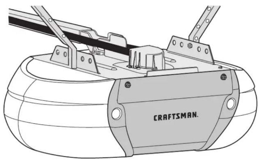
USER MANUAL CMXEOCG781 Craftsman
SMART GARAGE DOOR OPENER
For Residential Use Only
MODEL CMXEOCG781

natural_image
Technical line drawing of a mechanical assembly with labeled 'CRAFTSMAN.' component (no other text or symbols)READ AND FOLLOW ALL SAFETY RULES AND OPERATING INSTRUCTIONS BEFORE FIRST USE OF THIS PRODUCT.
FASTEN THE MANUAL NEAR THE GARAGE DOOR AFTER INSTALLATION.
PERIODIC CHECKS OF THE OPENER ARE REQUIRED TO ENSURE SAFE OPERATION.
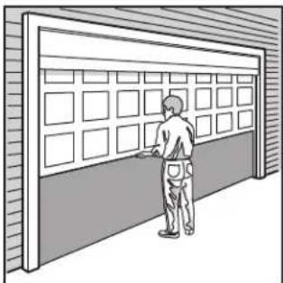
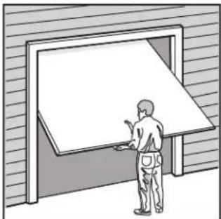
DO NOT INSTALL ON A ONE-PIECE DOOR IF USING DEVICES OR FEATURES PROVIDING UNATTENDED CLOSE.
UNATTENDED DEVICES AND FEATURES ARE TO BE USED ONLY WITH SECTIONAL DOORS. SEE PAGE 3.
WRITE DOWN THE CRAFTSIGNAL NUMBER LOCATED ON THE GARAGE DOOR OPENER:

WWW.CRAFTSMAN.COM
TABLE OF CONTENTS
INTRODUCTION 3-9
Safety Symbol Review and Signal Word Review ....3
Unattended Operation....3
Preparing your Garage Door 4
Test the Wi-Fi ^® Strength in Your Garage .....5
Tools Needed....5
Planning 6-7
Carton Inventory 8
Hardware Inventory....9
ASSEMBLY 10-13
Assemble the Rail and Install the Trolley 10
Fasten the Rail to the Motor Unit 10
Install the Idler Pulley....11
Install the Belt 12
Tighten the Belt 12
Install the Sprocket Cover ....13
INSTALLATION 13-29
Installation Safety Instructions....13
Determine the Header Bracket Location ....14
Install the Header Bracket 15
Attach the Rail to the Header Bracket 16
Position the Opener....17
Hang the Opener 18
Install the Lights....19
Attach the Emergency Release Rope and Handle 19
Fasten the Door Bracket 20-21
Connect Door Arm to Trolley 22-23
Attach the Warning Labels 23
Install the LCD Door Control 24
Install the Safety Reversal System 25-27
Electrical Requirements 28
Aligning the Safety Reversing Sensors 29
ADJUSTMENT 30-32
Introduction....30
Program the Travel 31
Test the Safety Reversal System 32
Test the Safety Reversing Sensors 32
BATTERY BACKUP 33
Install the Battery....33
Test the Battery....33
Charge the Battery ....33
Battery Status LED 33
myQ® SMARTPHONE CONTROL 34
Connect With Your Smartphone 34
OPERATION 35-41
Important safety instructions ....35
Features 36
LCD Door Control....37
Programming 39
To Erase the Memory 40
To Open the Door Manually ....41
Care of Your Opener 41
TROUBLESHOOTING 42-43
REPAIR PARTS 44-45
Rail Assembly Parts 44
Installation Parts 44
Motor Unit Assembly Parts 45
ACCESSORIES 46
WARRANTY 46
AUTOMATIC GARAGE DOOR OPENER SAFETY & MAINTENANCE GUIDE 47-48
INTRODUCTION
SAFETY SYMBOL REVIEW AND SIGNAL WORD REVIEW
This garage door opener has been designed and tested to offer safe service provided it is installed, operated, maintained and tested in strict accordance with the instructions and warnings contained in this manual.

WARNING
Mechanical

WARNING
Electrical

CAUTION
When you see these Safety Symbols and Signal Words on the following will alert you to the possibility of serious injury or death if you do not comply with the warnings that accompany them. The hazard may come from a mechanical or from electric shock. Read the warnings carefully.
When you see this Signal Word on the following pages, it will alert possibility of damage to your garage door and/or the garage door oper not comply with the cautionary statements that accompany it. Read their carefully.

WARNING: This product can expose you to chemicals including lead, which are known to the State of California to cause cancer or birth defects or other reproductive harm. For more information go to www.P65Warnings.ca.gov
UNATTENDED OPERATION
The Timer-to-Close (TTC) feature and examples of unattended close and are to be used ONLY with sectional doors. Any device or feature that allows the door to close without being in the line of sight of the door is considered unattended close. The Timer-to-Close (TTC) feature and any myQ® devices are to be used ONLY with sectional doors.
PREPARING YOUR GARAGE DOOR
Before you begin:
- Disable locks and remove any ropes connected to the g
- Lift the door halfway up. Release the door. If balanced, place, supported entirely by its springs.
- Raise and lower the door to check for binding or stick binds, sticks, or is out of balance, call a trained door
- Check the seal on the bottom of the door. Any gap the bottom of the door must not exceed 1/4" (6 mm). reversal system may not work properly.
- The opener should be installed above the center of the torsion spring or center bearing plate in the way of that may be installed within 4 feet (1.2 m) to the left or See page 14.
WARNING
age prevent possible SERIOUS INJURY or DEATH:
it should stay in
• ALWAYS can a trained door systems technician if garage door binds,
g. or is out of balance. An unbalanced garage door may NOT reverse
required
systematic technician. NEVER technician. Never try to loosen, move or adjust garage door, door springs, cabl tween the floor and pulleys, the brackets or their hardware, ALL of which are under EXTREME otherwise the safety tension.
Disable ALL locks and remove ALL ropes connected to garage door BEFOI door. If there is a installation and operating garage door opener to avoid entanglement. header or wacket on a one-piece door if using devices or features prght DO NOT install on a one-piece door if using devices or features prght of the door center unattended close. Unattended devices and features are to be used Of with sectional doors.
natural_image
Line drawing of a person standing beside a large window with grid panels (no text or symbols)Sectional Door One-Piece Door
natural_image
Illustration of a person standing beside a large open door, viewed from the side (no text or symbols present)CAUTION
To prevent damage to garage door and opener:
- ALWAYS disable locks BEFORE installing and operating the opener.
- ONLY operate garage door opener at 120V, 60 Hz to avoid malfunction damage.
TEST THE W# SIGNAL STRENGTH IN YOUR GARAGE
Monitor and control your garage door from anywhere® Apping Yothe with need a router with Wi-Fi and a smartphone or other mobile devi mobile device is connected to your Wi-Fi network. Hold your mobile place where your garage door opener will be installed and check strength.
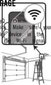
Check Signal Strength. If you see:


Wi-Fi signal is strong.
You're all set!
Install your new garage door opener.
Wi-Fi signal is weak.
The garage door opener will likely connect to your Wi-Fi network. If not, try one of the options below.
No Wi-Fi signal.
Try one of the following:
- Move your router closer to the garage door opener to minimize interference from walls and other objects
• Buy a Wi-Fi range extender
Visit support.chamberlaingroup.com for more details
See my App Control page 34 to connect your garage door opener to network. Do NOT connect prior to installation.
Wi-Fi® is a registered trademark of Wi-Fi Alliance
TOOLS NEEDED
During assembly, installation and adjustment of the opener, instructions will call for hand tools as illustrated below.
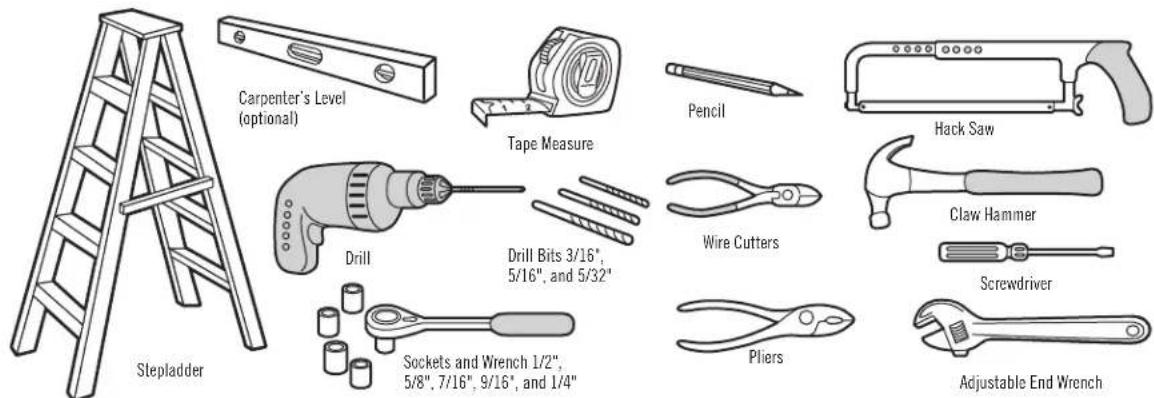
PLANNING
Identify the type and height of your garage door. Survey your garage area to see if any of the conditions below apply to your installation. Additional materials may be the garage door where it meets the floor. Any gap be required. You may find it helpful to refer back to this page and the accompanying illustrations as you proceed with the installation of your opener. Depending on Adjustment Step 2. Floor or door should be repaired. Your requirements, there are several installation steps which may call for materials or hardware not included in the carton.
- Installation Step 1 - Look at the wall or ceiling above to SECTIONAL DOOR INSTALLATION The header bracket must be securely fastened to structural supports.
- Installation Step 5 - Do you have a finished ceiling in your garage? You have a steel, aluminum, fiberglass or glass panel door? so, a support bracket and additional fastening hardware may be horizontal and vertical reinforcement is required (Installation Step 8 required.
- The opener should be installed above the center of the door. If
- Installation Step 12 – Depending upon garage construction, extension torsion spring or center bearing plate in the way of the header brackets or wood blocks may be needed to install sensors. may be installed within 4 feet (1.22 m) to the left or right
- Installation Step 12 - Alternate floor mounting of the safety reverseter. See Installation Steps 1 and 8. sensor will require hardware not provided.
- If your door is more than 7 feet (2.13 m) high, see rail ext
- Do you have an access door in addition to the garage door? If listed, on Accessories page. emergency key release is required.
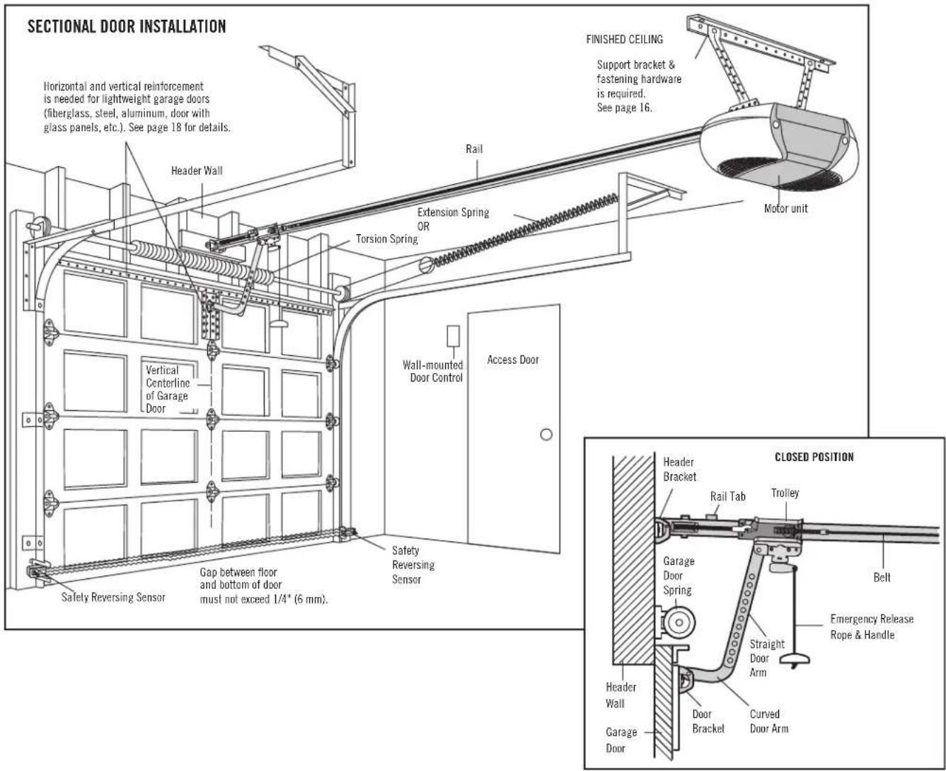
PLANNING (CONTINUED)
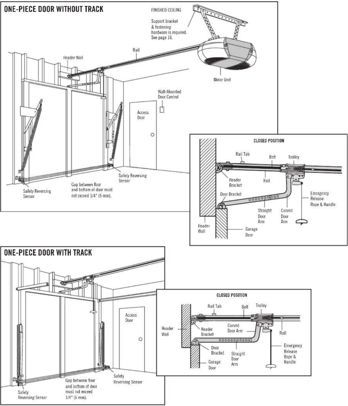
ONE-PIECE DOOR INSTALLATIONS
- Generally, a one-piece door does not require reinforcement. lightweight, refer to the information relating to sectional Installation Step 8.
- Depending on your door's construction, you may need additional hardware for the door bracket (Installation Step 8).
WARNING
Without a properly installed safety reversing sensor, persons (particularly if children) could be SERIOUSLY INJURED or KILLED by a closing garage poors in
- The gap between the bottom of the garage door and the floor MUS
onal opening/4" (6 mm). Otherwise, the safety reversal system may NOT
properly.
• The floor or the garage door MUST be repaired to eliminate the ga
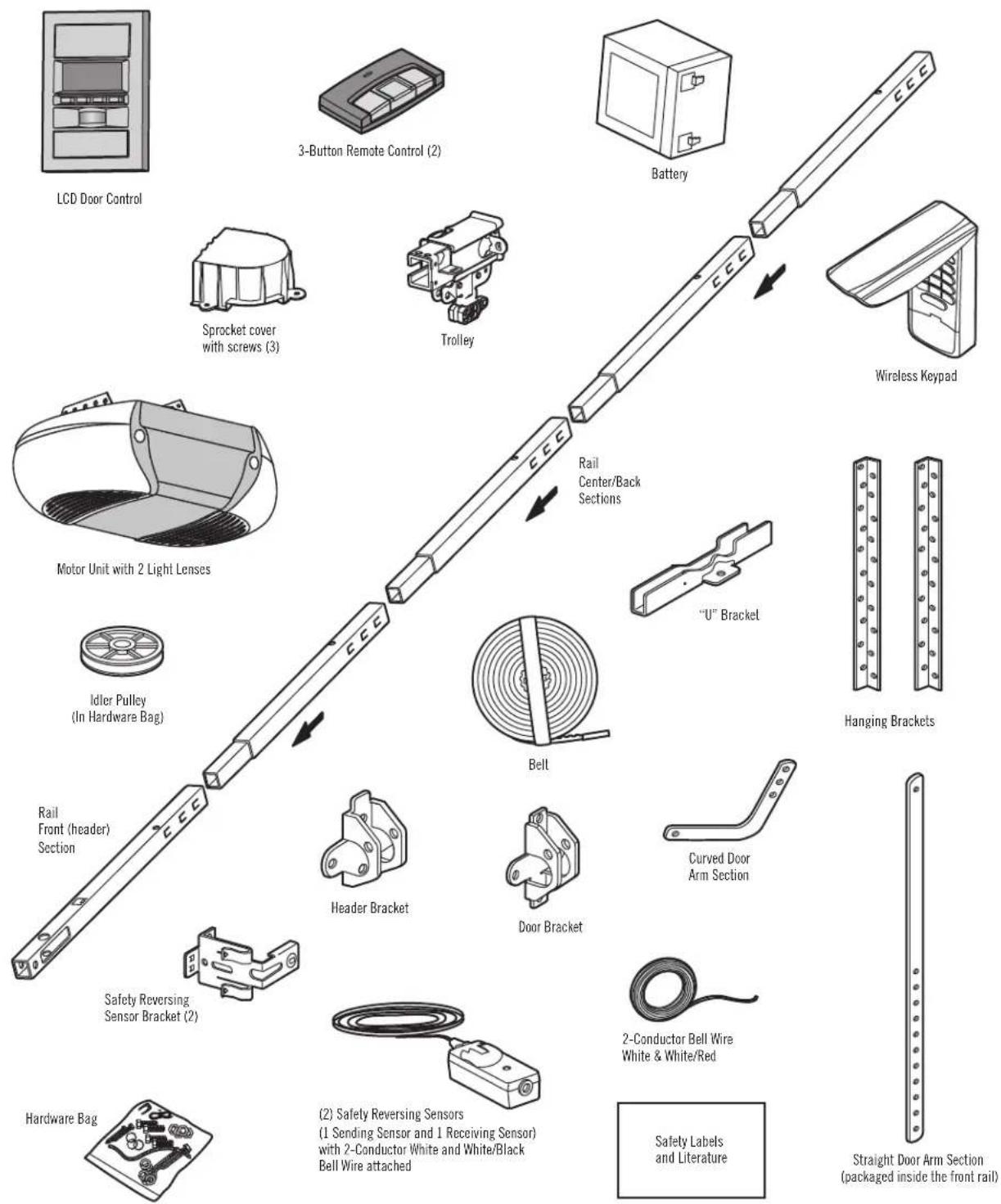
CARTON INVENTORY
Your garage door opener is packaged in one carton which contains Hardware motor assembly and installation is shown on the next page. Sa and all parts illustrated below. Accessories will depend on the mode art purchased packing material until installation and adjustment is complete. If anything is missing, carefully check the packing material.
HARDWARE INVENTORY
Separate all hardware and group as shown below for the assembly and installation procedures.
ASSEMBLY HARDWARE

Lock Nut 1/4"-20

Lock Washer 3/8"

Nut 3/8"
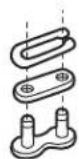
Master Link
natural_image
Line drawing of a hexagonal bolt with threaded shaft (no text or symbols on the bolt itself)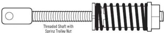
INSTALLATION HARDWARE
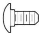
Carriage Bolt 1/4"-20x1/2" (2)
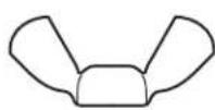
Wing Nut 1/4"-20 (2)
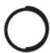
Ring
Fastener (3)

Nut 5/16"-18 (4)
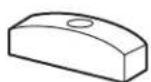
Handle
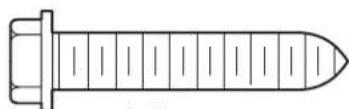
Lag Screw
5/16"-9x1-5/8" (4)
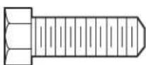
Hex Bolt
5/16"-18x7/8" (4)

Lock Washer 5/16" (4)
Insulated Staples (Not shown)
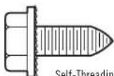
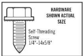
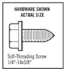
Self-Threading Screw 1/4"-14x5/8" (2)
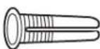
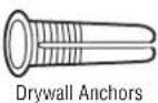
Drywall Anchors (2)
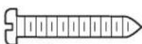
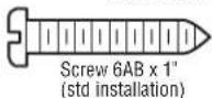
Screw
6ABx1" (2)
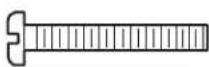
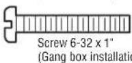
Screw 6-32x1" (2)
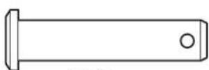
Clevis Pin
5/16"x1-1/2"
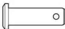
Clevis Pin 5/16"x1"
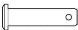
Clevis Pin
5/16"x1-1/4"
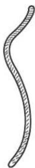
Rope
ASSEMBLY STEP 1
ASSEMBLE THE RAIL AND INSTALL THE TROLLEY
To avoid installation difficulties, do not run the garage door instructed to do so.
CAUTION
To prevent INJURY from pinching, keep hands and fingers away while assembling the rail.
from the
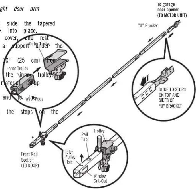
The front rail has a cut out "window" at the door end. The front rail has a rail tab. This tab MUST be on the top of the rail when assembled.
- Remove the straight door arm and hanging bracket packaged inside the
front rail and set aside for Installation Step 5 and 9. NOTE: To prevent
INJURY while unpacking the rail carefully remove the straight door arm stored within the rail section. - Align the rail sections on a flat surface as shown and slide the tapered ends into the larger ones. Tabs along the side will lock into place.
- Place the motor unit on packing material to protect the cover, and rest the back end of the rail on top. For convenience, put a support under the front end of the rail.
- As a temporary stop, insert a screwdriver into the hole 10" (25 cm) from the front end of the rail, as shown. Inner Trolley
- Check to be sure there are 4 plastic wear pads inside the inner tip. If they became loose during shipping, check all packing material. Snap them back into position as shown.
- Slide the trolley assembly along the rail from the back end to the wdr pads screwdriver.
- Slide the rail onto the "U" bracket, until it reaches all the stops on the top and sides of the "U" bracket.
ASSEMBLY STEP 2
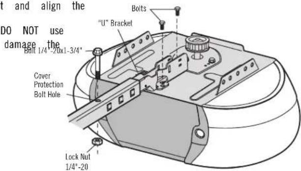
FASTEN THE RAIL TO THE MOTOR UNIT
-
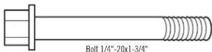
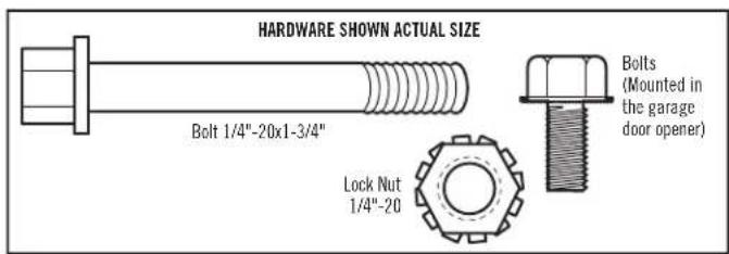
Insert a 1/4"-20 x 1-3/4" bolt into the cover protection back end of the rail as shown. Tighten securely with a DO NOT overtighten.
-
Remove the bolts from the top of the motor unit.
-
Use the carton to support the front end of the rail.
-
Place the "U" bracket, flat side down onto the motor unit and align the bracket holes with the bolt holes.
-
Fasten the "U" bracket with the previously removed bolts; any power tools. The use of power tools may permanently garage door opener.
To avoid on Serious damage to garage door opener, use ONLY those bolts/fasteners mounted in the top of the opener.
CAUTION
ASSEMBLY STEP 3
INSTALL THE IDLER PULLEY
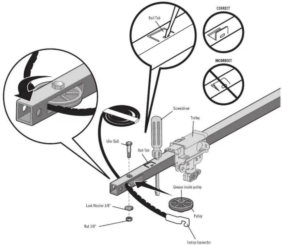
- Lay the belt beside the rail, as shown. Grasp the end with the hooked trolley connector and pass approximately 12" (30 cm) of belt through the window. Keep the ribbed side toward the rail, and allow it to hang until Assembly Step 4.
- Remove the tape from the idler pulley. The inside center should be pre-greased. If dry, regrease to ensure proper operation.
- Place the idler pulley into the window as shown.
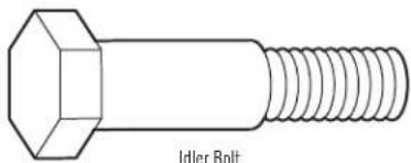
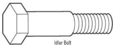
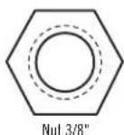
- Insert the idler bolt from the top through the rail and pulley. Tighten with a 3/8" lock washer and nut underneath the rail until the lock washer is compressed.
- Rotate the pulley to be sure it spins freely.
- Locate the rail tab. The rail tab is between the idler bolt and the trolley in the front rail section. Use a flathead screwdriver and lift the rail tab until the tab is vertical (90°).
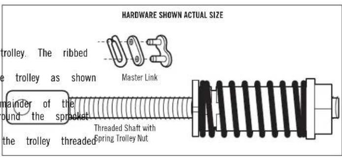
HARDWARE SHOWN ACTUAL SIZE

ASSEMBLY STEP 4
INSTALL THE BELT
- Pull the belt around the idler pulley and toward the side must contact the pulley.
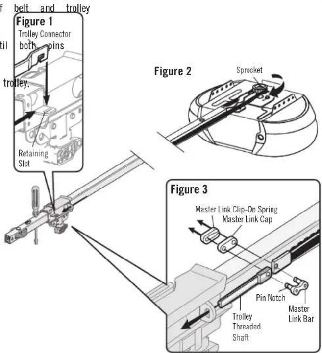
- Hook the trolley connector into the retaining slot on (Figure 1).
- With the trolley against the screwdriver, dispense the belt along the rail length toward the motor unit and (Figure 2). The sprocket teeth must engage the belt.
-
Check to make sure the belt is not twisted. Connect shaft with the master link (Figure 3).
-
Push pins of master link bar through holes in end of threaded shaft.
- Push master link cap over pins and past pin notches.
-
Slide clip-on spring over cap and onto pin notches until are securely locked in place.
-
Remove the spring trolley nut from the threaded shaft.
-
Insert the trolley threaded shaft through the hole in the
ASSEMBLY STEP 5
TIGHTEN THE BELT
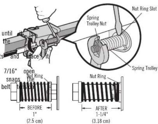
- By hand, thread the spring trolley nut on the threaded shaft finger tight against the trolley. Do not use any tools. Remove screwdriver.
- Insert a flathead screwdriver tip into one of the nut ring slot firmly against the trolley.
- Tighten the spring trolley nut with an adjustable wrench or a end wrench about a quarter turn until the spring releases and nut ring against the trolley. This sets the spring to optimum
ASSEMBLY STEP 6
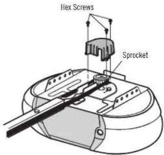
INSTALL THE SPROCKET COVER
- Position the sprocket cover over the sprocket as shown mounting plate with #8x3/8" hex screws provided.
WARNING
and To avoid possible SERIOUS INJURY to finger from moving garage
- ALWAYS keep hand clear of sprocket while operating opener.
- Securely attach sprocket cover BEFORE operating.
You have now finished assembling your garage door opener. Please read the following warnings before proceeding to the installation section.
HARDWARE SHOWN ACTUAL SIZE
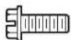
Hex Screw #8x3/8"
(Packed with the
sprocket cover)
INSTALLATION
IMPORTANT INSTALLATION INSTRUCTIONS
WARNING
To reduce the risk of SEVERE INJURY or DEATH:
- READ AND FOLLOW ALL INSTALLATION WARNINGS AND INSTRUCTIONS. Install wall-mounted garage door control:
- Install garage door opener ONLY on properly balanced and lubricated garage sight of the garage door.
door. An improperly balanced door may NOT reverse when required and outludof reach of small children at a minimum height of 5 feet result in SEVERE INJURY or DEATH. (1.5 m) above floors, landings, steps or any other adjacent wa - ALL repairs to cables, spring assemblies and other hardware MUST be surface.
by a trained door systems technician BEFORE installing opener. • away from ALL moving parts of the door. - Disable ALL locks and remove ALL ropes connected to garage0. doPlaceBEORmpment warning label on wall next to garage door control installing opener to avoid entanglement. prominent location.
- Where possible, install the door opener 7 feet (2.13 m) or 11 more placebo emergency release/safety reverse test label in plain view on ins floor. garage door.
- Mount the emergency release within reach, but at least 6 feet Upon3 complete of installation, test safety reversal system. Door MUST the floor and avoiding contact with vehicles to avoid accidental release. on contact with a 1-1/2" (3.8 cm) high object (or a 2x4 la
- NEVER connect garage door opener to power source until instructed to do so.
- NEVER wear watches, rings or loose clothing while installing 10 Servicing install on a one-piece door if using devices or features p opener. They could be caught in garage door or opener mechanism attended close. Unattended devices and features are to be used ON sectional doors.
INSTALLATION STEP 1
DETERMINE THE HEADER BRACKET LOCATION
WARNING
To prevent possible SERIOUS INJURY or DEATH:
- Header bracket MUST be RIGIDLY fastened to structural support wall or ceiling, otherwise garage door might NOT reverse who DO NOT install header bracket over drywall.
- Concrete anchors MUST be used if mounting header bracket masonry.
- NEVER try to loosen, move or adjust garage door, springs, or pulleys, brackets, or their hardware, ALL of which are under tension.
- ALWAYS call a trained door systems technician if garage door sticks, or is out of balance. An unbalanced garage door m reverse when required.
Installation procedures vary according to garage door types. Follow the which apply to your door.
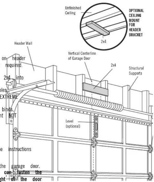
- Close the door and mark the inside vertical centerline of the garage door.
- Extend the line onto the header wall above the door. You can fasten the header bracket within 4 feet (1.22 m) of the left or right of the door center only if a torsion spring or center bearing plate is in the way; or you can attach it to the ceiling (see page 15) when clearance is minimal. (It may be mounted on the wall upside down if necessary, to gain
approximately 1/2" (1 cm). If you need to install the header bracket 2x4 (on wall or ceiling), use lag screws (not provided) to securely fasten-2" (5 cm) Track the 2x4 to structural supports as shown here and on page 15. Open your door to the highest point of travel as shown. Draw an intersecting horizontal line on the header wall above the high point:
- 2" (5 cm) above the high point for sectional door and one-piece door track.
- 8" (20 cm) above the high point for one-piece door without track.
This height will provide travel clearance for the top edge of the door.
NOTE: If the total number of inches exceeds the height available in your garage, use the maximum height possible, or refer to page 15 for ceiling installation.
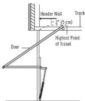
One-piece door with horizontal track
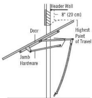
One-piece door without track: jamb hardware
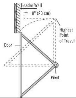
One-piece door without track: pivot hardware
INSTALLATION STEP 2
INSTALL THE HEADER BRACKET
You can attach the header bracket either to the wall above the garage the ceiling. Follow the instructions which will work best for your particular requirements. Do not install the header bracket over drywall. If installing masonry, use concrete anchors (not provided).
WALL HEADER BRACKET INSTALLATION
- Center the bracket on the vertical centerline with the bottom edge of the bracket on the horizontal line as shown (with the arrow pointing toward the ceiling). — Header Wall
- Mark the vertical set of bracket holes. Drill 3/16" pilot holes and fasten the bracket securely to a structural support with the hardware provided.
Figure 1
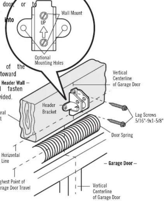
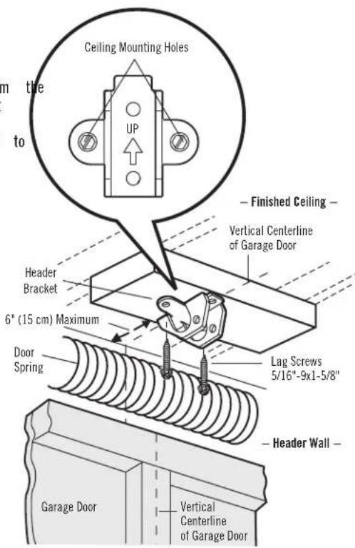
CEILING HEADER BRACKET INSTALLATION
- Extend the vertical centerline onto the ceiling as shown.
- Center the bracket on the vertical mark, no more than 6" (15 cm) from wall. Make sure the arrow is pointing away from the wall. The bracket can be mounted flush against the ceiling when clearance is minimal.
- Mark the side holes. Drill 3/16" pilot holes and fasten bracket securely to a structural support with the hardware provided.
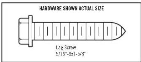
Figure 2
INSTALLATION STEP 3
ATTACH THE RAIL TO THE HEADER BRACKET
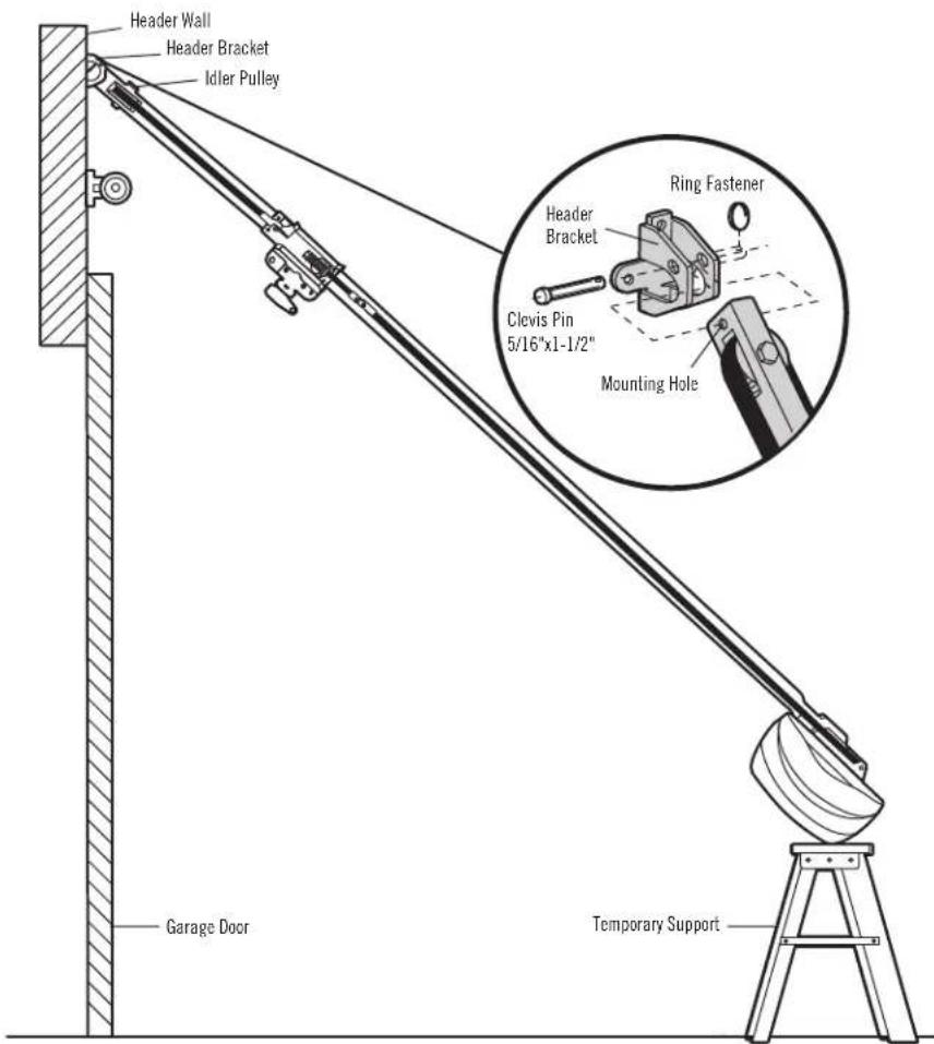
- Position the opener on the garage floor below the header bracket. Use packing material as a protective base.
NOTE: If the door spring is in the way, you will need help. Have someone hold the opener securely on a temporary support to allow the rail to clear the spring.
- Position the rail bracket against the header bracket.
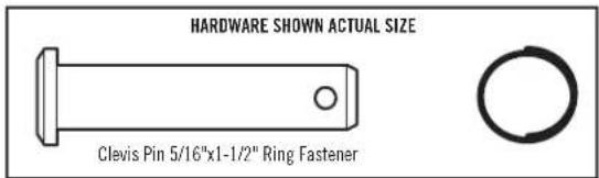
- Align the bracket holes and join with a clevis pin as shown.
- Insert a ring fastener to secure.
INSTALLATION STEP 4
POSITION THE OPENER
Follow instructions which apply to your door type as illustrated.
CAUTION
To prevent damage to garage door, rest garage door opener on top section of door.
rail on
SECTIONAL DOOR OR ONE-PIECE DOOR WITH TRACK
A 2x4 laid flat is convenient for setting an ideal door-to-rail distance.
- Raise the opener onto a stepladder. You will need help at this ladder is not tall enough.
- Open the door all the way and place a 2x4 laid flat on the beneath the rail (Figure 1).
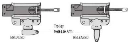
- If the top section or panel hits the trolley when you raise the down on the trolley release arm to disconnect inner and outer s Slide the outer trolley toward the motor unit. The trolley can rer disconnected until Installation Step 12 is completed.
ONE-PIECE DOOR WITHOUT TRACK
A 2x4 on its side is convenient for setting an ideal door-to-rail distance.
- Raise the opener onto a stepladder. You will need help at this point if the ladder is not tall enough.
- Open the door all the way and place a 2x4 on its side on the top section of the door beneath the rail (Figure 2).
- The top of the door should be level with the top of the motor unit. Do not position the opener more than 4" (10 cm) above this point. Figure 2
Figure 1
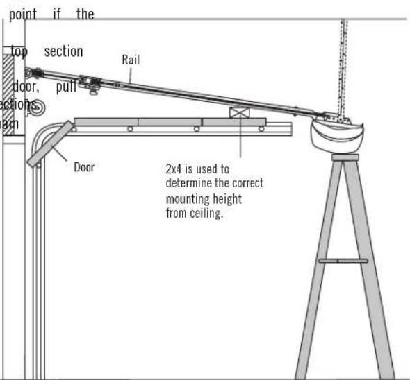
Figure 2
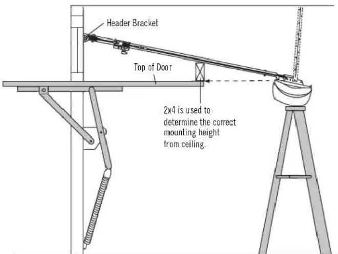
INSTALLATION STEP 5
HANG THE OPENER

WARNING
To avoid possible SERIOUS INJURY from a falling garage door SECURELY to structural supports of the garage. Concrete anchors used if installing ANY brackets into masonry.
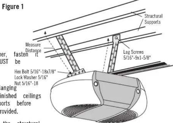
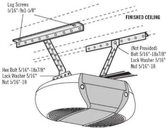
Three representative installations are shown. Yours may be different. Hanging brackets should be angled (Figure 1) to provide rigid support. On finished ceilings (Figures 2 and 3), attach a sturdy metal bracket to structural supports before installing the opener. This bracket and fastening hardware are not provided.
- Measure the distance from each side of the motor unit to the structural support.
- Cut both pieces of the hanging bracket to required lengths.
- Drill 3/16" pilot holes in the structural supports.
- Attach one end of each bracket to a support with 5/16"-9x1-5/8" screws.
- Fasten the opener to the hanging brackets with 5/16"-18x7/8" hex lock washers and nuts.
- Check to make sure the rail is centered over the door (or header bracket if the bracket is not centered above the door).
- Remove the 2x4. Operate the door manually. If the door hits the header bracket.
NOTE: DO NOT connect power to opener at this time.
the str Figure 2
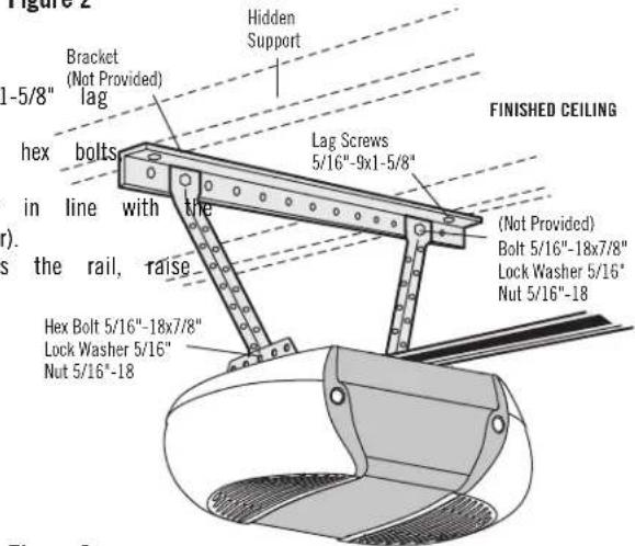
Figure 3
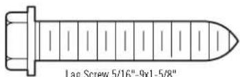
HARDWARE SHOWN ACTUAL SIZE
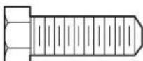
Hex Bolt
5/16"-18x7/8"

Nut 5/16"-18

Lock Washer 5/16"
INSTALLATION STEP 6
INSTALL THE LIGHTS
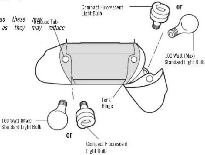
- Press the release tabs on both sides of lens. Gently downward until the lens hinge is in the fully open p remove the lens.
- Insert an A19 incandescent (100 watt maximum) or com (26W, 100W equivalent) light bulb into the light socket. turn ON and remain lit for approximately 4-1/2 minutes connected. Then the lights will turn OFF.
- Reverse the procedure to close the lens.
- If the bulbs burn out prematurely due to vibration, rep door opener bulb. Use A19, standard neck garage door replacement.
CAUTION
| To prevent possible OVERHEATING of the end panel or light socket: rotate lens back and position Use ONLY A19 incandescent (100W maximum) or compact fluorescent (26' maximum) light bulbs. pact fluorescent DO NOT use incandescent bulbs larger than 100W. The DO NOT use compact fluorescent light bulbs larger than 26W (100W when power is equivalent). DO NOT use halogen bulbs. DO NOT use short neck or specialty light bulbs. place with a garage |
opener for
NOTE: Do not use halogen, short neck, or specialty light bulbs as these overheat the end panel or light socket. Do not use LED bulbs as they the range or performance of your remote control(s).
INSTALLATION STEP 7
ATTACH THE EMERGENCY RELEASE ROPE AND HANDLE
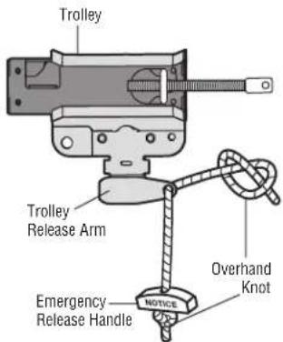
- Insert one end of the emergency release rope through the sure that "NOTICE" is right side up. Secure with an over 1" (2.5 cm) from the end of the rope to prevent slipping;
- Insert the other end of the emergency release rope through trolley release arm. Mount the emergency release within react 6 feet (1.83 m) above floor, avoiding contact with vehicles accidental release and secure with an overhand knot.
NOTE: If it is necessary to cut the emergency release rope, seal match or lighter to prevent unraveling. Ensure the emergency release handle are above the top of all vehicles to avoid entanglement.
WARNING
| To prevent make possible SERIOUS INJURY or DEATH from a falling garage d |
| rhand knot at least |
| . If possible, use emergency release handle to disengage trolley ONLY w |
| ng. garage door is CLOSED. Weak or broken springs or unbalanced door |
| h the hole in the |
| result in an open door falling rapidly and/or unexpectedly. |
| ch. NEVER use least emergency release handle unless garage doorway is clear |
| to prevent |
| persons and obstructions. |
| . NEVER use handle to pull door open or closed. If rope knot become |
| you could fall |
| the cut end with a |
| se rope and |
INSTALLATION STEP 8
FASTEN THE DOOR BRACKET
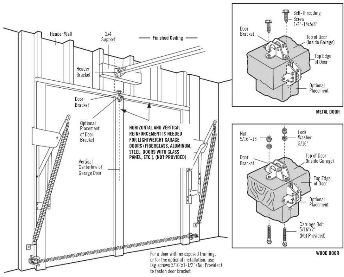
Follow instructions which apply to your door type as illustrated be following page.
A horizontal reinforcement brace should be long enough to be three vertical supports. A vertical reinforcement brace should cover the top panel.
Figure 1 shows one piece of angle iron as the horizontal brace. brace, 2 pieces of angle iron are used to create a U-shaped solution is to check with your garage door manufacturer for an door reinforcement kit.
NOTE: Many door reinforcement kits provide for direct attachment of and door arm. In this case you will not need the door bracket.
SECTIONAL DOORS
- Center the door bracket on the previously marked vertical for the header bracket installation. Note correct UP placement stamped inside the bracket.
- Position the top edge of the bracket 2"-4" (5-10 cm) below of the door, OR directly below any structural support across door.
- Mark, drill holes and install as follows, depending on your construction.
Metal or light weight doors using a vertical angle iron brace panel support and the door bracket:
- Drill 3/16" fastening holes. Secure the door bracket using the two 1/4"-14x5/8" self-threading screws. (Figure 2A)
- Alternately, use two 5/16"-18x2" bolts, lock washers and nuts provided). (Figure 2B)
Metal, insulated or light weight factory reinforced doors:
- Drill 3/16" fastening holes. Secure the door bracket using the threading screws. (Figure 3)
Wood doors:
- Use top and bottom or side to side door bracket holes. Through the door and secure bracket with 5/16"-18x2" carriage washers and nuts (not provided). (Figure 4)
NOTE: The 1/4"-14x5/8" self-threading screws are not intended for figure 2A wood doors.
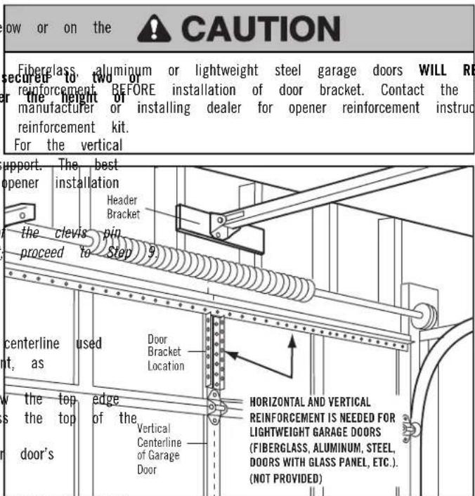
between the door Figure 1
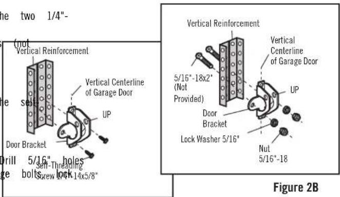
Figure 2Awood
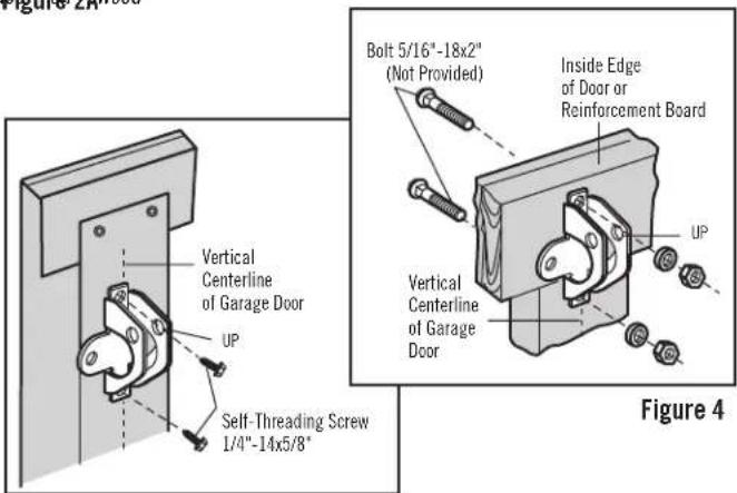
Figure 3
FASTEN THE DOOR BRACKET (CONTINUED)
ONE-PIECE DOORS
Please read and comply with the warnings and reinforcement instructions on the previous page. They apply to one-piece doors also.
- Center the door bracket on the top of the door, in line with the header bracket as shown. Mark either the left and right, or the top and bottom holes.
- Metal Doors: Drill 3/16" pilot holes and fasten the bracket with the 1/4"-14x5/8" self-threading screws provided.
- Wood Doors: Drill 5/16" holes and use 5/16"x2" carriage bolts, lock washers and nuts (not provided) or 5/16"x1-1/2" lag screws (not provided) depending on your installation needs.
NOTE: The door bracket may be installed on the top edge of the door if required for your installation. (Refer to the dotted line optional placement drawing.)
INSTALLATION STEP 9
CONNECT DOOR ARM TO TROLLEY
Follow instructions which apply to your door type as illustrated below and following page.
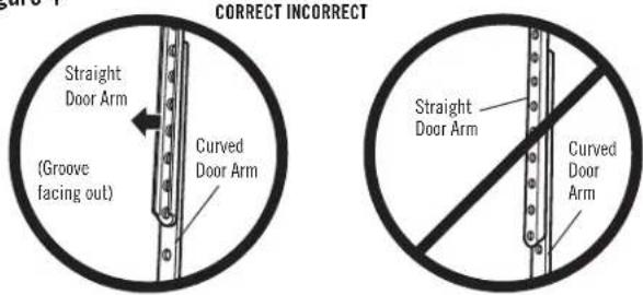
IMPORTANT: The groove on the straight door arm MUST face away from the door arm (Figure 4).
SECTIONAL DOORS ONLY
- Make sure garage door is fully closed. Pull the emergency release to disconnect the outer trolley from the inner trolley. Slide the outer back (away from the pulley) about 8" (20 cm) as shown in Figure 3.
- Fasten straight door arm section to outer trolley with the 5/16"x1" pin. Secure the connection with a ring fastener (Figure 1).
- Fasten curved section to the door bracket in the same way, using 5/16"x1-1/4" clevis pin.
- Bring arm sections together. Find two pairs of holes that line up and join sections. Select holes as far apart as possible to increase door arm rigidity (Figure 2).
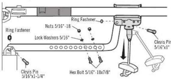
Hole alignment alternative (Figure 3):
- If holes in curved arm are above holes in straight arm, disconnect arm. Cut about 6" (15 cm) from the solid end. Reconnect to trolle end down as shown.
- Bring arm sections together.
- Find two pairs of holes that line up and join with bolts, lock nuts.
Pull the emergency release handle toward the opener at a 45^ angle so that the trolley release arm is horizontal. Trolley will re-engage automatically when opener is operated during the adjustments.
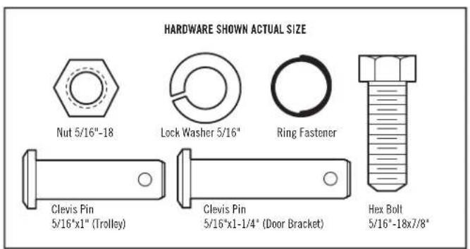
Figure 1
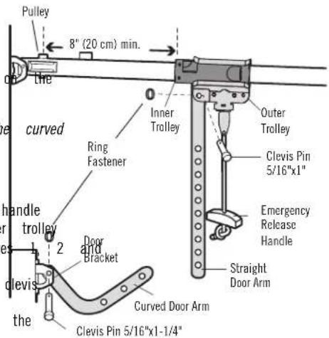
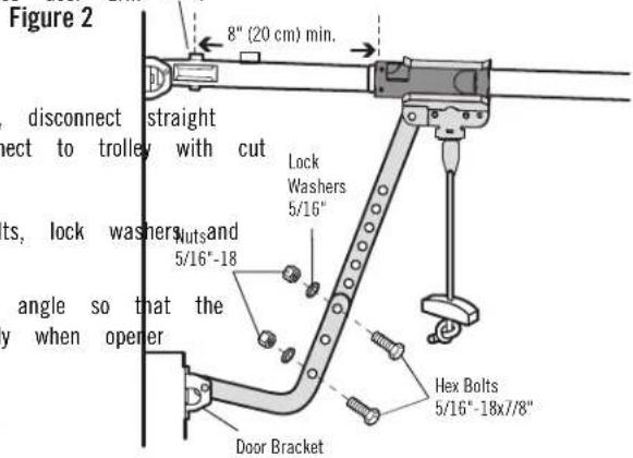
Figure 3
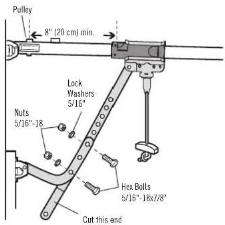
Figure 4
CONNECT DOOR ARM TO TROLLEY (CONTINUED)
ALL ONE-PIECE DOORS
IMPORTANT: The groove on the straight door arm MUST face away from door arm (Figure 5).
- Close the door. Disconnect the trolley by pulling the emergency handle.
- Fasten the straight door arm and the curved door arm together to the longest possible length (with a 2 or 3 hole overlap) using the bolts and lock washers.
- Attach the straight door arm to the door bracket using the 5/16"x1-1/4" clevis pin. Secure with the ring fastener.
- Attach the curved door arm to the trolley using the 5/1 Secure with the ring fastener.
- Pull the emergency release handle toward the garage door the trolley release arm is horizontal.
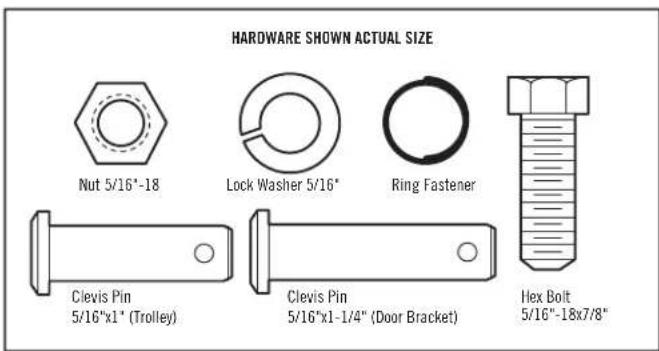
Figure 5
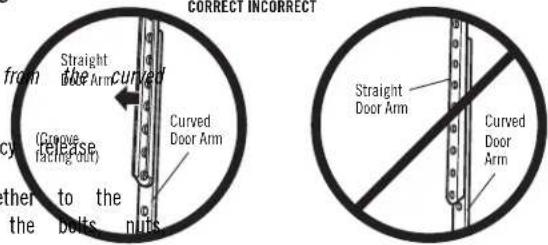
Figure 6 One-Piece Door Without Track "x1" clevis pin.
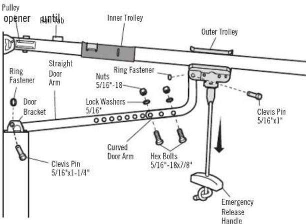
Figure 7 One-Piece Door With Track
INSTALLATION STEP 10
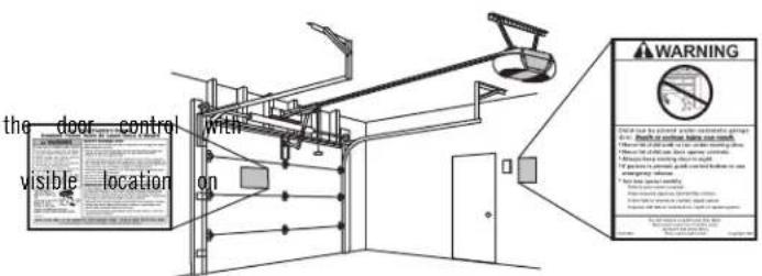
ATTACH THE WARNING LABELS
- Attach the entrapment warning label on the wall near tacks or staples.
- Attach the manual release/safety reverse test label in a the inside of the garage door.
INSTALLATION STEP 11
INSTALL THE LCD DOOR CONTROL
INTRODUCTION
NOTE: Older door controls and third party products are not compa Install the door control within sight of the door at a minimum m) above floors, landings, steps or any other adjacent walking su small children cannot reach, and away from the moving parts of
NOTE: For gang box installations it is not necessary to drill hole drywall anchors. Use the existing holes in the gang box.
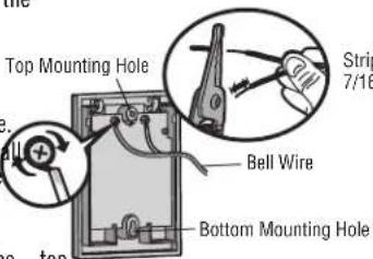
WIRE THE DOOR CONTROL (FIGURE 1)
- Strip 7/16" (11 mm) of insulation from one end of the the wires.
- Connect one wire to each of the two screws on the b control. The wires can be connected to either screw. Pre-wired installations: Choose any two wires to connect, of which wires are used so that the correct wires are garage door opener in a later step.
MOUNT THE DOOR CONTROL (FIGURE 2)
- Mark the location of the bottom mounting hole and drill a 5/32" hole.
- Install the bottom screw, allowing 1/8" (3 mm) to protrude from the wa
- Position the bottom hole of the door control over the screw and slide down into place.
- Lift the push bar and mark the top hole.
- Remove the door control from the wall and drill a 5/32" hole for the screw.
- Position the bottom hole of the door control over the screw and slide down into place. Attach the top screw. Figure 2
WIRE THE DOOR CONTROL TO THE GARAGE DOOR OPENER (FIGURE 3)
Pre-wired installations: When wiring the door control to the garage door opener make sure you use the same wires that are connected to the door control.
- Run the white and red/white wire from the door control to the garage opener. Attach the wire to the wall and ceiling with the staples (not applicable for gang box or pre-wired installations). Do not pierce the wire with the staple as this may cause a short or an open circuit.
- Strip 7/16" (11 mm) of insulation from the other end of the wire ne garage door opener.
- Connect the wire to the red and white terminals on the garage door opener.
HARDWARE SHOWN ACTUAL SIZE
Insulated Staples (Not shown)
WARNING
To prevent possible SERIOUS INJURY or DEATH from electrocution:
- Be sure power is NOT connected BEFORE installing door control. - Connect door control ONLY to 12 VOLT low voltage wires. Height of 5 feet (1.5) Face White To prevent possible SERIOUS INJURY or DEATH from a closing ga
the door. Door control within sight of garage door, out of reach of s children at a minimum height of 5 feet (1.5 m) above floors, landing steps or any other adjacent walking surface, and away from ALL parts of door.
- NEVER permit children to operate or play with door control push by remote control transmitters. wire Active separate ONLY when it can be seen clearly, is properly adjusted there are no obstructions to door travel.
ck. ALWAYS keep garage door in sight until completely closed. NEVER p anyone to cross path of closing garage door. make note
connected to the
Figure 1
Strip wire 7/16" (11 mm)
Figure 2
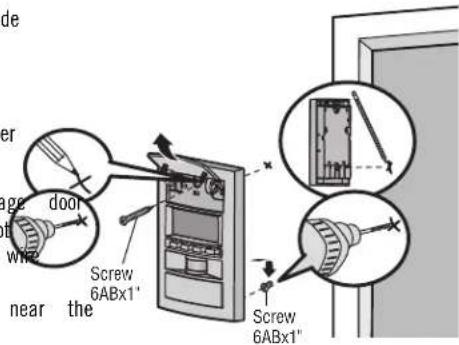
Figure 3

INSTALLATION STEP 12
IMPORTANT INFORMATION ABOUT THE SAFETY REVERSING SENSORS
The safety reversing sensors must be connected and aligned
garage door opener will move in the down direction.
The sending sensor (with an amber LED) transmits an invisible I receiving sensor (with a green LED). If an obstruction breaks the the door is closing, the door will stop and reverse to the full garage door opener lights will flash 10 times.
NOTE: For energy efficiency the garage door opener will enter sleep mode when garag the floor. door is fully closed. The sleep mode shuts the garage door opener down until activated. The sleep mode is sequenced with the garage door opener lights; as the lights turns off, the sensor LEDs will turn off and whenever the garage door opener lights turn on, the sensor LEDs will light. The garage door opener will not go into the sleep mode until the garage door opener has completed 5 cycles upon power up.
When installing the safety reversing sensors check the following:
- Sensors are installed inside the garage, one on either side of the door.
- Sensors are facing each other with the lenses aligned and the receiving sensor lens does not receive direct sunlight.
- Sensors are no more than 6 inches (15 cm) above the floor and the light beam is unobstructed.
WARNING
Be sure power is NOT connected to the garage door opener
correctly before reversing sensor.
To prevent SERIOUS INJURY or DEATH from closing garage door:
lightCorrection conflict and align the safety reversing sensor. This opensafety device and must NOT be disabled.
• Install the safety reversing sensor so beam is NO HIGHER
madeve where the floor.
er down until
.
required
than 6"
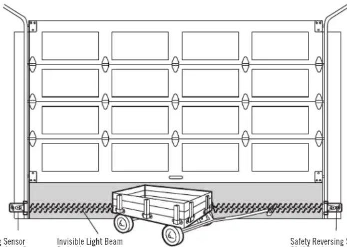
Safety Reversing Sensor 6" (15 cm) max. above floor
Invisible Light Beam Protection Area
Safety Reversing Sensor 6" (15 cm) max. above floor
Facing the door from inside the garage
INSTALL THE SAFETY REVERSAL SYSTEM (CONTINUED)
INSTALLING THE BRACKETS
Be sure power to the opener is disconnected. Install and align the brackets sensors will face each other across the garage door, with the beam no higher 6" (15 cm) above the floor. They may be installed in one of three ways as
Garage door track installation (preferred):
- Slip the curved arms over the rounded edge of each door track, curved arms facing the door. Snap into place against the side of track. It should lie flush, with the lip hugging the back edge of as shown in Figure 1.
If your door track will not support the bracket securely, wall installation is recommended.
Wall installation (Figures 2 and 3):
- Place the bracket against the wall with curved arms facing the door. sure there is enough clearance for the sensor beam to be unobstructed.
- If additional depth is needed, an extension bracket (see Accessories) or wood blocks can be used.
- Use bracket mounting holes as a template to locate and drill (2) 3/16" diameter pilot holes on the wall at each side of the door, no higher 6" (15 cm) above the floor.
- Attach brackets to wall with lag screws (not provided).
- If using extension brackets or wood blocks, adjust right and left assemblies to the same distance out from the mounting surface. Make sure all door hardware obstructions are cleared.
Floor installation (Figure 4):
- Use wood blocks or extension brackets (see Accessories) to elevate sensor brackets so the lenses will be no higher than 6" (15 cm) above the floor.
- Carefully measure and place right and left assemblies at the same distance out from the wall. Be sure all door hardware obstructions are cleared.
- Fasten to the floor with concrete anchors as shown.
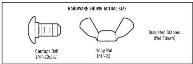
Figure 1
DOOR TRACK MOUNT (RIGHT SIDE)
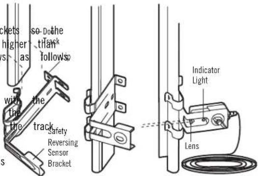
Figure 2
WALL MOUNT (RIGHT SIDE)
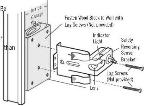
WALL MOUNT (RIGHT SIDE)
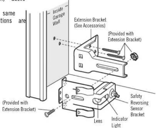
Figure 4
FLOOR MOUNT (RIGHT SIDE)
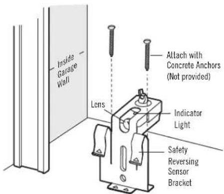
INSTALL THE SAFETY REVERSAL SYSTEM (CONTINUED)
MOUNTING AND WIRING THE SAFETY REVERSING SENSORS
Mounting:
- Slide a 1/4"-20 x 1/2" carriage bolt head into the slot on each section, nuts to fasten sensors to brackets, with lenses pointing toward each other across the door. Be sure the lens is not obstructed by a bracket extension (Figure 5).
- Finger tighten the wing nuts.
Option A - Installation Without Pre-Wiring:
- Run the bell wire from both sensors to the garage door opener. wire to the wall and ceiling with the staples (Figure 6).
Option B - Pre-Wired Installation:
If your garage already has wires installed for the safety reversing sensors, follow the instructions below:
- Cut the end of the safety sensor wire, making sure there is enough wire to reach the pre-installed wires from the wall (Figure 7). Figure 7
- Separate the safety sensor wires and strip 7/16" (11 mm) of insulation from each end. Choose two of the pre-installed wires and strip 7/16" (11 mm) of insulation from each end. Make sure that you choose the same color pre-installed wires for each sensor (Figure 8).
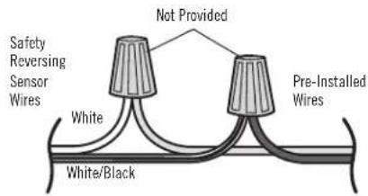
- Connect the pre-installed wires to the sensor wires with making sure the colors correspond for each sensor (Figure
CONNECT TO GARAGE DOOR OPENER:
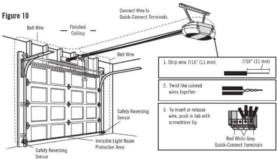
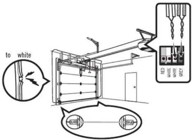
- Strip 7/16" (11 mm) of insulation from each set of wires. Separate and white/black wires sufficiently to connect to the opener quick-co terminals. Twist like colored wires together. Insert wires into quick-connect holes: white to white and white/black to grey (Figure 10).
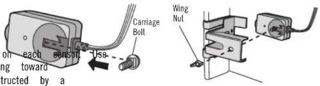
Figure 6
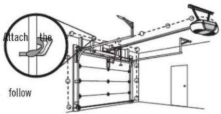
Figure 8
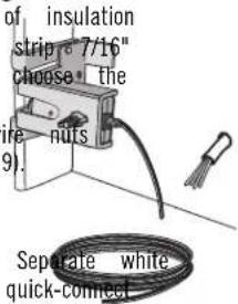
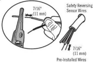
Figure 9
INSTALLATION STEP 13
ELECTRICAL REQUIREMENTS
To avoid installation difficulties, do not run the opener at this
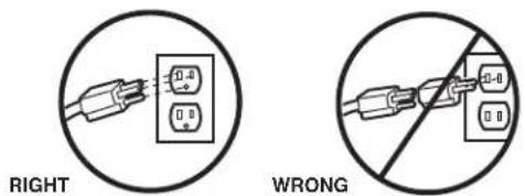
To reduce the risk of electric shock, your garage door opener has plug with a third grounding pin. This plug will only fit into a If the plug doesn't fit into the outlet you have, contact a qual install the proper outlet.
WARNING
To prevent possible SERIOUS INJURY or DEATH from electrocution or fire
- a Be grounding power is NOT connected to the opener, and disconnect pow circuit BEFORE removing cover to establish permanent wiring connection type outlet. Garage door installation and wiring MUST be in compliance with ALLied electrical and building codes.
- NEVER use an extension cord, 2-wire adapter, or change plug in A make it fit outlet. Be sure the opener is grounded.
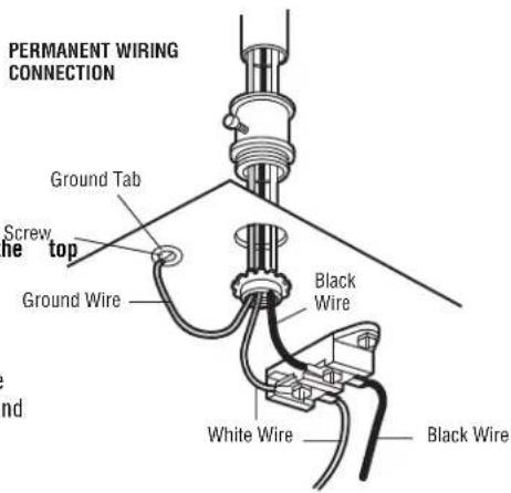
If permanent wiring is required by your local code, refer to the following procedure. To make a permanent connection through the 7/8 inch hole in the of the motor unit (according to local code):
- Remove the motor unit cover screws and set the cover aside.
- Remove the attached 3-prong cord.
- Connect the black (line) wire to the screw on the brass terminal; the white (neutral) wire to the screw on the silver terminal; and the ground wire to the green ground screw. The opener must be grounded.
- Reinstall the cover.
INSTALLATION STEP 14
ALIGNING THE SAFETY REVERSING SENSORS
The door will not close if the sensors have not been installed and aligned correctly.
When the light beam is obstructed or misaligned while the door is closing, door will reverse and the garage door opener lights will flash ten times. If is already open, it will not close.
- Check to make sure the LEDs in both sensors are glowing steadily. LEDs in both sensors will glow steadily if they are aligned and wire correctly.
The sensors can be aligned by loosening the wing nuts, aligning the tightening the wing nuts.
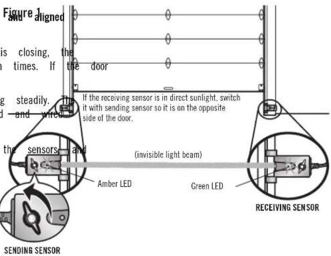
IF THE AMBER LED ON THE SENDING SENSOR IS NOT GLOWING:
- Make sure there is power to the garage door opener.
- Make sure the sensor wire is not shorted/broken.
- Make sure the sensor has been wired correctly: white wires terminal and white/black wires to grey terminal.
IF THE GREEN LED ON THE RECEIVING SENSOR IS NOT GLOWING:
- Make sure the sensor wire is not shorted/broken.
- Make sure the sensors are aligned.
ADJUSTMENT
INTRODUCTION
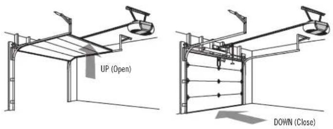
Your garage door opener is designed with electronic controls to m adjustments easy. The adjustments allow you to program where the in the open (UP) and close (DOWN) position. The electronic control amount of force required to open and close the door. The force automatically when you program the travel.
NOTE: If anything interferes with the door's upward travel it will interferes with the door's downward travel, it will reverse.
WARNING
Without a properly installed safety reversal system, persons (particularly small set-up children) could be SERIOUSLY INJURED or KILLED by a closing door will stop s sense the incorrect adjustment of garage door travel limits will interfere with operation of safety reversal system.
- After ANY adjustments are made, the safety reversal system MUST b stop. tested. Door. MUST reverse on contact with 1-1/2" (3.8 cm) high o 2x4 laid flat) on floor.
CAUTION
To prevent damage to vehicles, be sure fully open door provides a clear clearance.
ONE-PIECE DOORS ONLY
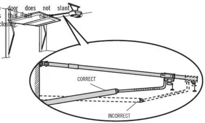
When setting the UP travel for a one-piece door ensure that the backwards when fully open (UP). If the door is slanted backwards unnecessary bucking and/or jerking when the door is opening or cl
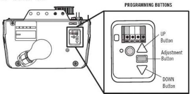
PROGRAMMING BUTTONS
The programming buttons are located on the left side panel of the garage door opener and are used to program the travel.
ADJUSTMENT STEP 1
PROGRAM THE TRAVEL
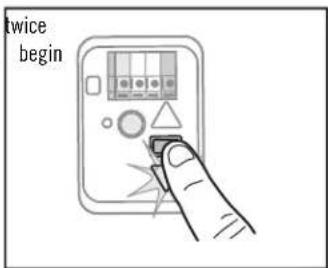
- Press and hold the Adjustment Button until the UP Button begins to flash and/or a beep is heard.
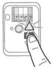
- Press and hold the UP Button
until the door is in t UP position. NOTE: The DOWN Buttons can be move the door up and needed.
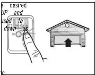
- Once the door is in the
desired UP position press and release the Adjustment Button. The garage door opener lights will flash twice and the DOWN Button will begin to flash. IMPORTANT NOTE: For one-piece door installations refer to page 30.
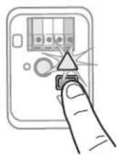
- Press and hold the DOWN
Button until the door is in the desired DOWN position. NOTE:
The UP and DOWN B be used to move the and down as needed.
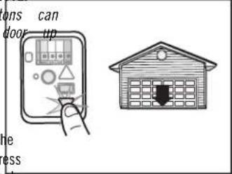
- Once the door is in the desired DOWN position press and release the Adjustment
Button. The garage door opener lights will flash and the UP Button will to flash.
WARNING
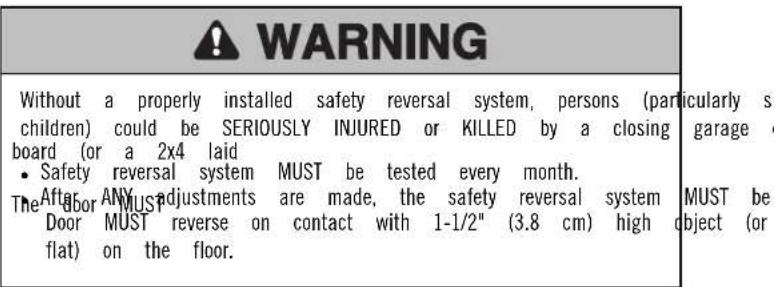
Without a properly installed safety reversal system, persons (particularly small children) could be SERIOUSLY INJURED or KILLED by a closing door.
- Incorrect adjustment of garage door travel limits will interfere with operation of safety reversal system.
-
After ANY adjustments are made, the safety reversal system tested. Door MUST reverse on contact with 1-1/2" (3.8 cm) high o 2x4 laid flat) on floor.
-
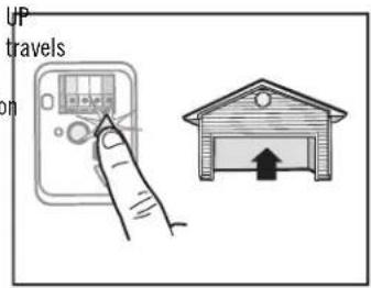
Press and release the UP Button. When the door to the programmed UP position, the DOWN Button will begin to flash.
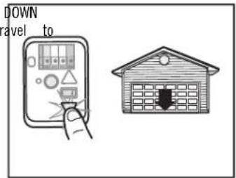
- Press and release the Button. The door will the programmed DOWN position. Programming is complete.
* If the garage door opener lights are flashing 5 times during the s the Travel, the programming has timed out. If the garage door opene flashing 10 times during the steps for Program the Travel, the safety sensors are misaligned or obstructed (refer to page 29). When the se aligned and unobstructed, cycle the door through a complete up and using the remote control or the UP and DOWN buttons. Programming If you are unable to operate the door up and down, repeat the ste Programming the Travel.
ADJUSTMENT STEP 2
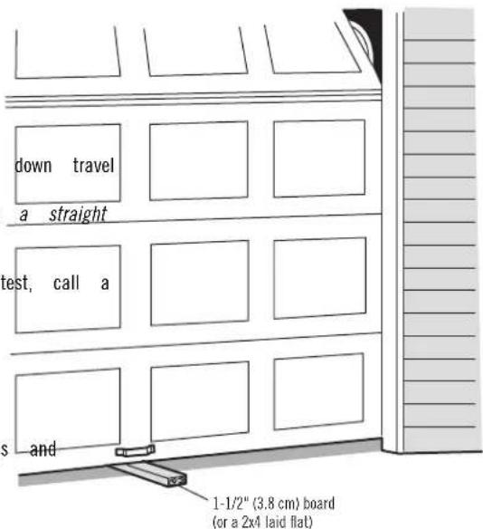
- With the door fully open, place a 1-1/2 inch (3.8 cm) flat) on the floor, centered under the garage door.
- Press the remote control push button to close the door. reverse when it makes contact with the board.
If the door stops but does not reverse:
- Review the installation instructions provided to insure all steps were followed;
- Repeat Program the Travel (see Adjustment Step 1);
- Repeat the Safety Reversal test.
If the test continues to fail, call a trained door systems technician.
ADJUST
- If the door stops and does not reverse on the obstruction, the needs to be increased (refer to Adjustment Step 1). NOTE: On a sectional door, make sure adjustments do not force the door arm beyond up and down position.
- Repeat the test.
- If the garage door opener continues to fail the safety reversal trained door systems technician.
IMPORTANT SAFETY CHECK:
Test the Safety Reverse System after:
• Each adjustment of door arm length, limits, or force controls.
- Any repair to or adjustment of the garage door (including springs hardware).
• Any repair to or buckling of the garage floor.
- Any repair to or adjustment of the opener.
ADJUSTMENT STEP 3
TEST THE SAFETY REVERSING SENSORS
- Press the remote control push button to open the door.
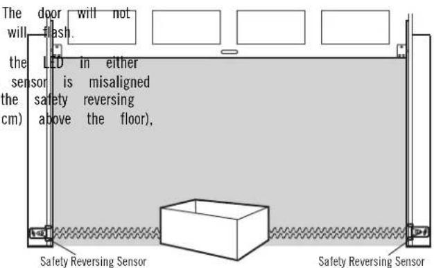
- Place the opener carton in the path of the door.
- Press the remote control push button to close the door. move more than an inch (2.5 cm), and the opener lights
The garage door opener will not close from a remote control if the safety reversing sensor is off (alerting you to the fact that the sensor or obstructed). If the garage door opener closes the door when the sensor is obstructed (and the sensors are no more than 6" (15 cm) call for a trained door systems technician.
WARNING
Without a properly installed safety reversing sensor, persons (particularly children) could be SERIOUSLY INJURED or KILLED by a closing garage
BATTERY BACKUP
INSTALL THE BATTERY
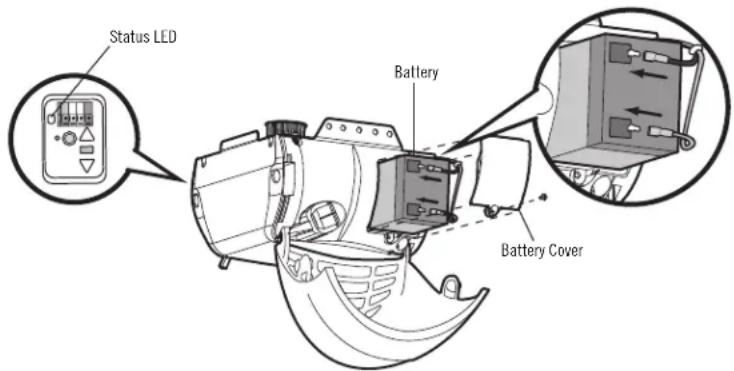
- Unplug the garage door opener.
- Open the light lens on the right side panel of the a Phillips head screwdriver to remove the battery cover door opener.
- Partially insert the battery into the battery compartment terminals facing out.
- Connect red (+) and black (-) wires from the garage corresponding terminals on the battery.
- Replace the battery cover.
- Plug in the garage door opener.
- Wait for the green Battery Status LED to start flashing to test the battery.
WARNING
To reduce the risk of FIRE or INJURY to persons:
garage Donnect ALL electric and battery power BEFORE performing ANY ser on the or maintenance.
• Use only battery part # G4228 for replacement battery.
• the DO NOT dispose of battery in fire. Battery may explode.
codes for disposal instructions.
opener to the
CAUTION
before proceeding
ALWAYS wear protective gloves and eye protection when changing the I or working around the battery compartment.
TEST THE BATTERY
-
Unplug the garage door opener. The battery status LED solid orange indicating opener is operating on battery p indicating low battery power. NOTE: Make sure the garage door opener is unplugged.
-
Open and close the door using the remote control or garage door opener may run slower if the battery is battery will take 24 hours to fully charge.
-
Plug in the garage door opener. Verify the battery sta green, indicating the battery is charging.
BATTERY STATUS LED
NOTE:the gloBattery Status LED is most visible with the garage door op. Batterywilloeslashot have to be fully charged to operate the garage door
GREEN LED:
All control. The are normal. fully charged. The
- A solid green LED light indicates the battery is fully charged.
LED • iA flashing green LED indicates the battery is being charged.
CHARGE THE BATTERY
ORANGE LED:
The battery charges when the garage door opener is plugged into a 110Vac electrical outlet that has power and requires 24 hours to fully charge. A fully charged battery supplies 12Vdc to the garage door opener for one to two sdays orange LED with beep, sounding approximately every 2 seconds normal operation during an electrical power outage. After the electrical power indicates the garage door opener is operating on battery power. been restored, the battery will recharge within 24 hours. The battery willA latashing orange LED with beep, sounding every 30 seconds, in approximately 1 to 2 years with normal usage. Instructions for replacementthearebattery is low.
provided with the battery. To obtain maximum battery life and prevent damage, disconnect the battery when the garage door opener is unplugged for an extended
period of time, such as a summer or winter home.
RED LED:
The garage door opener's 12V battery needs to be replaced.
NOTE: When the garage door opener is in battery backup mode the opener lights, Timer-to-Close, and Remote Close features are unavailable.
garage door A solid red LED with beep, sounding every 30 seconds, indicates battery will no longer hold a charge and needs to be replaced for replacement battery to allow your system to operate during a outage.
myQ® SMARTPHONE CONTROL
CONNECT WITH YOUR SMARTPHONE
YOU WILL NEED:
• Wi-Fi enabled smartphone, tablet or laptop
- Broadband Internet Connection
• Wi-Fi signal in the garage (2.4 Ghz, 802.11b/g/n required), see 5
- Password for your home network (router's main account, not network)
- myQ ^® serial number located on the garage door opener
DOWNLOAD THE @myAPP TO SET UP AN ACCOUNT AND CONNECT
Open and close your door, get alerts and set schedules from anywhere. Connected smart garage door openers also receive software updates to ensure the opener has the latest operational features.
- Download the App.
- Set up an account and connect.
For more information on connecting your garage door opener, visit support.chamberlaingroup.com.
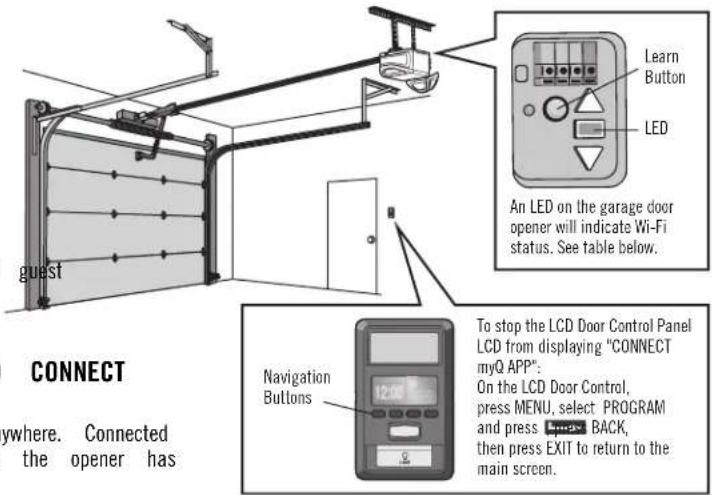
| WI-FI STATUS | |
| LED Definition | |
| Blue Off - Wi-Fi is not turned on.Blinking - Garage door opener is in Wi-Fi leaSolid - Mobile device connected to the garage. | |
| Blue and Greer | Blinking - Attempting to connect to router. |
| Green Blinking | - Attempting to connect to the Internet server.Solid - Wi-Fi has been set up and garage connected to the internet. |
NOTES:
myQ® App control WILL NOT work if the garage door opener is operatin, power.
To erase the Wi-Fi settings, see 40.
OPERATION
IMPORTANT SAFETY INSTRUCTIONS


WARNING
To reduce the risk of SEVERE INJURY or DEATH:
- READ AND FOLLOW ALL WARNINGS AND INSTRUCTIONS.
- ALWAYS keep remote controls out of reach of children. NEVER permit to operate or play with garage door control push buttons or remote Safetrols reversal system MUST be tested every month. Garage door
- ONLY activate garage door when it can be seen clearly, it is properly on contact with 1-1/2" (3.8 cm) high object (or a 2x4 adjusted, and there are no obstructions to door travel. on the floor. Failure to adjust the garage door opener properly
- ALWAYS keep garage door in sight and away from people and objects increases the risk of SEVERE INJURY or DEATH. completely closed. NO ONE SHOULD CROSS THE PATH OF THE MOVING ALDOORS KEEP GARAGE DOOR PROPERLY BALANCED (see page 4).
- NO ONE SHOULD GO UNDER A STOPPED, PARTIALLY OPENED DOOR. improperly balanced door may NOT reverse when required and could be possible, use emergency release handle to disengage trolley ONLY would in SEVERE INJURY or DEATH.
garage door is CLOSED. Use caution when using this release with 2. the ALL door repairs to cables, spring assemblies and other hardware, ALL open. Weak or broken springs or unbalanced door could result in an when are under EXTREME tension, MUST be made by a trained door falling rapidly and/or unexpectedly and increasing the risk of SEVEREMs technician.
INJURY or DEATH. - NEVER use emergency release handle unless garage doorway is clear BEFORE making ANY repairs or removing covers.
persons and obstructions. - This operator system is equipped with an unattended operation
- NEVER use handle to pull garage door open or closed. If rope knot become the door could move unexpectedly. NO ONE SHOULD CRO: untied, you could fall. THE PATH OF THE MOVING DOOR.
- DO NOT install on a one-piece door if using devices or feature providing unattended close. Unattended devices and features are to used ONLY with sectional doors.
16. SAVE THESE INSTRUCTIONS.
FEATURES
Your garage door opener is equipped with features to provide you control over your garage door operation.
myQ® (DO NOT ENABLE ON ONE-PIECE DOORS)
myQ® technology uses a 900 MHz signal to provide two-way comm between the garage door opener® and blendyQaccessories. Your garage opener is compatible with up ®tacce&someQ
TIMER-TO-CLOSE (DO NOT ENABLE ON ONE-PIECE DOORS)
The Timer-to-Close feature automatically closes the door after a special period that can be adjusted using the door control. Prior to the will be an audible and visual alert.
REMOTE CONTROLS AND DOOR CONTROLS
Your garage door opener has already been programmed at the face with your remote control, which changes with each use, randomly 100 billion new codes.
| myQ®Accessories | MEMORY | CAPACITY |
| Remote Controls Up to 8 | ||
| Door Controls Up to 2 myQ | ®door controls | |
| Keyless Entries Up to 1 | ||
When properly connected and aligned, the safety reversing sensors obstruction in the path of the infrared beam. If an obstruction beam while the door is closing, the door will stop and reverse position, and the opener lights will flash 10 times. If the door the safety reversing sensors are not installed, or are misaligned, close from a remote control. However, you can close the door on the door control or keyless entry until the door is fully close reversing sensors do not effect the opening cycle.
ENERGY GREATE CONSERVATION
For energy efficiency the garage door opener will enter sleep mode when is fully closed. The sleep mode shuts the garage door opener down up. The sleep mode is sequenced with the garage door opener light bulb; incubation turns off the sensor LEDs will turn off and whenever the garage lights turn on the sensor LEDs will light. The garage door opener will the sleep mode until the garage door opener has completed 5 cycles up.
LIGHTS
The garage dosing dotherepener light bulbs will turn on when the opener is in; power is restored after interruption, or when the garage door opener activated. The lights will turn off automatically after 4-1/2 minutes. An incandescent A19 light bulb (100 watt maximum) or for maximum energy a 26W (100W equivalent) compact fluorescent light (CFL) bulb may be story to operate
BATTERY BACKUP
The battery backup system allows access in and out of your garage, a power is out. When the garage door opener is operating on battery port garage door opener will run slower, the light will not function, the Ba LED will glow solid orange, and a beep will sound approximately every
USING YOUR GARAGE DOOR OPENER
The garage door opener can be activated through a wall-mounted door remote control, wireless keyless entry® access.
When the door is closed and the garage door opener is activated the open. If the door senses an obstruction or is interrupted while opening will affect When the door is in any position other than closed and then be aware the activated the door will close. If the garage door opener sens obstruction, while closing, the door will reverse. If the obstruction interrupt sensor fully be open, the garage door opener lights will blink 10 times. However, these do the wloor not if you hold the button on the door control or keyless door is hold fully the closed.
ed. The safety The safety reversing sensors do not affect the opening cycle. The safety sensor must be connected and aligned correctly before the garage door move in the down direction.
LCD DOOR CONTROL
SYNCHRONIZE THE DOOR CONTROL
To synchronize the door control to the garage door opener, press the garage door opener activates (it may take up to 3 presses). control by pressing the push bar, each press of the push bar garage door opener.
USING THE LCD DOOR CONTROL
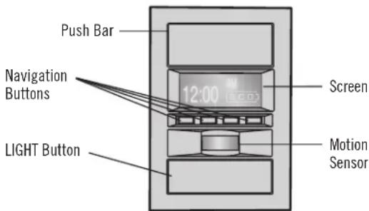
PUSH BAR
Press the push bar to open or close the door.
LIGHT BUTTON
Press the LIGHT button to turn the garage door opener lights on lights are turned on they will stay on until the LIGHT button is until the garage door opener is activated. Once the garage door is activated the lights will turn off after the specified period of time setting is 4-1/2 minutes). The LIGHT button will not control the door is in motion.
NAVIGATION BUTTONS
Use the navigation buttons to make selections and program feature
SCREEN
The screen will display the time and temperature until the menu pressed, and then it will display the menu options. If there is a garage door opener the screen will display the Diagnostic Code. I Troubleshooting section.
The following features are accessible through the screen using the na buttons on the LCD Door Control:
LEARN the device will activate the
Any compatible remote controls, wireless keyless entracement Q can be programmed to the garage door opener by accessing the menu and navigation buttons on the LCD Door Control.
LOCK
The LOCK feature is designed to prevent activation of the garage door remote controls while still allowing activation from the door control and entry. This feature is useful for added peace of mind when the home vacation).
TIMER-TO-CLOSE (TTC)
DO NOT enable TTC if operating a one-piece door. TTC is to be used in sectional doors.
Factory default is set to off. TTC can be set to automatically close door from the fully open position after a specified period of time (1, intervals). The LCD Door Control also has a custom setting up to 99 Garage door opener will beep and the lights will flash before closing screen on the door control will display the status of the TTC such a close, paused, or an error. If the door encounters an obstruction while a garage offdoor when pen there will make a second attempt to close the door. If a sobstressed again, nor been cleared after the second attempt, the garage openereverse open, stop and WILL NOT close until the obstruction has made the Factory WILL NOT work if the garage door opener is operating by lighter when if the safety reversing sensors are misaligned. This feature is intended to be the primary method of closing the door. A keyless engine installed in the event of an accidental lock out when using this fan
AUTOMATIC LIGHT
Motion Sensor
Factory default is set to on. This feature will automatically turn on the button lights when motion is sensed. The lights will come on for the problem with the time, then shut off. Refer to the
If using the garage door opener light as a work light disable the A Feature, otherwise the light will turn off automatically if you are beyond of the sensor.
Light Feature
The lights will turn on when someone enters through the open garage safety reversing sensor infrared beam is broken.
LCD DOOR CONTROL (CONTINUED)
SCREEN AND MENU NAVIGATION
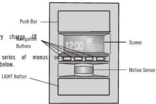
The main screen displays the time, temperature, and current battery applicable).
The features on the door control can be programmed through a series of menus the screen and the navigation buttons. Refer to the descriptions below.
FEATURES
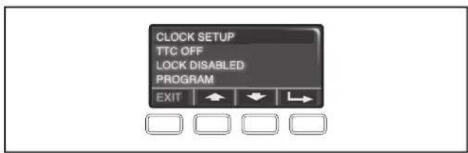
Press the navigation button below "MENU" to view the Features
Clock Setup: Set the time, choose 12 or 24 hour clock and show/ hide clock.
TTC settings (for sectional doors only): Set the Timer-to-Close set the time interval before door closes. NOTE: DO NOT enable TTC if operating a one-piece door. TTC is to be used ONLY with sectional doors.
Lock: Enable/disable lock.
Program: Add remote controls, an extra remote button to control opener lights, or a keyless entry.
SETTINGS
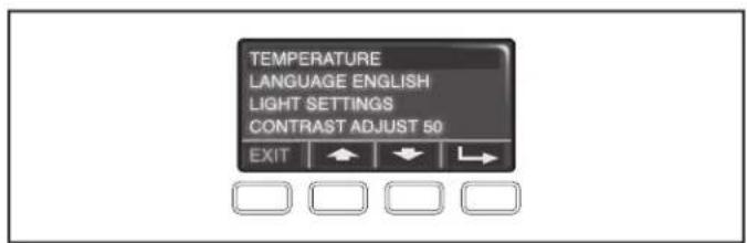
Press the navigation button below the down arrow till you see TEMPERA menu the Settings menu.
Temperature: Display the temperature in Fahrenheit or Celsius and show/h feature on/off and
Language: Select a language (English, French, or Spanish).
Light Settings: Set duration for garage door opener light to stay on a selectable range of 1-1/2 to 4-1/2 minutes. Turn the Motion sensor off/ the entry light feature off/on. your garage door
Contrast: Adjust the contrast of the screen.
To program a remote control or keyless entry to the garage door open door control see page 39.
PROGRAMMING
Your garage door opener has been programmed at the factory to operate with your remote control. Older accessories are not compatible. See page 46 for compatible accessories. Programming can be done through the door control or the learn button on the garage door opener. To program additional remote controls refer to the instructions provided with the additional remote controls.
IMPORTANT NOTE: If your vehicle is equipped with you Homelinkrequire an external adapter depending on the make, model and year of your www.homelink.com for additional information.
PROGRAM A REMOTE USING THE LEARN BUTTON
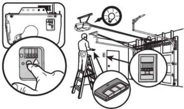
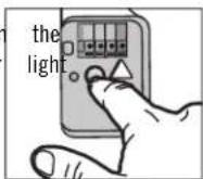
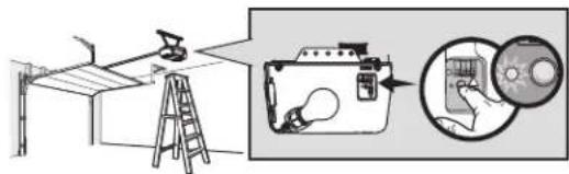
- Press and release the Learn button on garage door opener. The Learn indicator will glow steadily for 30 seconds.
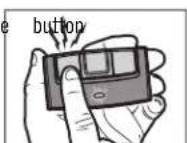
- Within 30 seconds, press and hold the on the remote control.
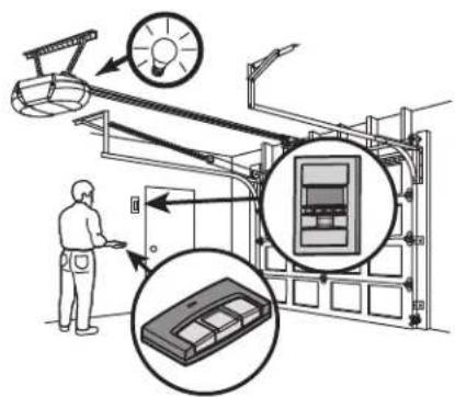
- Release the button when the garage d opener light blinks. It has learned the light bulbs are not installed, two click heard.

When replacing the light lens cover, ensure the antenna wires are down.
TO ADD, REPROGRAM, OR CHANGE A REMOTE CONTROL/ KEYLESS ENTRY THE LCD DOOR CONTROL
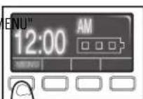
- Press the navigation button below "ME to view the Features menu.
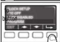
- Use the navigation buttons to scroll "PROGRAM" and press the navigation under to continue.
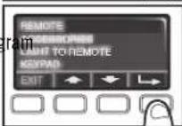
- Select "REMOTE" or "KEYPAD" to program from the program menu. Press to continue.
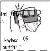
- Press the button on the remote control you wish to operate your garage door.
Enter a 4-digit personal identification number (PIN) of your choice on the entry keypad. Then press the ENTER
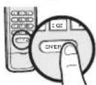
TO ERASE THE MEMORY
ERASE ALL REMOTE CONTROLS AND KEYLESS ENTRIES
ERASE THE CONNECTION FROM GARAGE DOOR OPENER TO
WI-FI NETWORK
- Press and hold the LEARN button on garage door opener LED goes out (approximately 6 seconds). All remote control entry codes are now erased. Reprogram any accessory you
until the learn
and 1. keypress and hold the black adjustment button on the garage door wish tountuse.3 beeps are heard (Approximately 6 seconds).
ERASE ALL DEVICES (INCLUDING ENAPCLED ACCESSORIES)
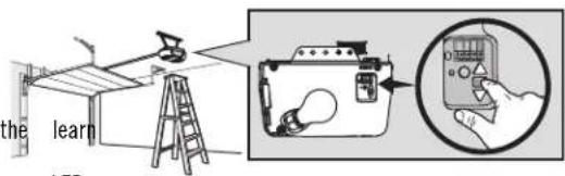
- Press and hold the LEARN button on garage door opener until the leaf LED goes out (approximately 6 seconds).
- Immediately press and hold the LEARN button again until the learn LED goes out. All codes are now erased. Reprogram any accessory you wish to use.
TO OPEN THE DOOR MANUALLY
- The door should be fully closed if possible.
- Pull down on the emergency release release arm handle so the trolley release arm covers the vertical position. The door can now be raised and lowered as often as necessary.
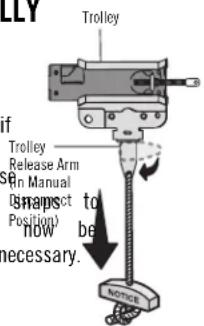
- Pull the emergency release handle (Note: the garage door opener so the trolley release arm snaps to the horizontal position. The trolley will reconnect on next UP or DOWN operation, either manually or by using the door control remote control.
Lockout position (Manual disconnect)
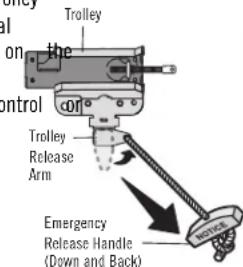
To reconnect
WARNING
To prevent possible SERIOUS INJURY or DEATH from a falling
- If possible, use emergency release handle to disengage trolley garage door is CLOSED. Weak or broken springs or unbalanced door result in an open door falling rapidly and/or unexpectedly.
- NEVER use emergency release handle unless garage doorway is clear persons and obstructions.
- NEVER use handle to pull door open or closed. If rope knot become you could fall.
ONLY w
d door
clear
t become
THE REMOTE CONTROL BATTERY
WARNING
To prevent possible SERIOUS INJURY or DEATH:
- NEVER allow small children near batteries.
- If battery is swallowed, immediately notify doctor.
To reduce risk of fire, explosion or chemical burn: - Replace ONLY with 3V CR2032 coin batteries.
• DO NOT recharge, disassemble, heat above 212°F (100°C) or
garage d
incinerate.
The Lithium battery should produce power to 3 years.
To replace battery, use the visor clip or screwdriver blade to pry open the case as shown. Insert battery positive side up (+).
Replace the battery with only 3V CR2032 coin cell batteries. Dispose of old battery properly.
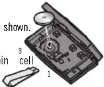
2
CARE OF YOUR OPENER
MAINTENANCE SCHEDULE
Every month
- Manually operate door. If it is unbalanced or binding, call a systems technician.
- Check to be sure door opens and closes fully. Adjust if nec page 30.
- Test the safety reversal system. Adjust if necessary, see page
Every year
- Oil door rollers, bearings and hinges. The garage door opener additional lubrication. Do not grease the door tracks.
- Test the battery backup and consider replacing the battery to door opener will operate during an electrical power outage, set the battery backup.
NOTICE: This device complies with Part 15 of the FCC rules and Industry Canada's license-exempt RSSs. Ope subject to the following two conditions: (1) this device may not cause harmful interference, and (2) this de accept any interference received, including interference that may cause undesired operation.
Any changes or modifications not expressly approved by the party responsible for compliance could void the authority to operate the equipment.
This device must be installed to ensure a minimum 20 cm (8 in.) distance is maintained between users/by obtained door
This device has been tested and found to comply with the limits for a Class B digital device, pursuant to the rules and Industry Canada ICES standard. These limits are designed to provide reasonable protection again harmful interference in a residential installation. This equipment generates, uses and can radiate radio frequency energy and, if not installed and used in accordance with the instructions, may cause harmful interference to communications. However, there is no guarantee that interference will not occur in a particular installation. If equipment does cause harmful interference to radio or television reception, which can be determined by turnin equipment off and on, the user is encouraged to try to correct the interference by one or more of the following measures:
• Reorient or relocate the receiving antenna.
up increase the separation between the equipment and receiver.
- Connect the equipment into an outlet on a circuit different from that to which the receiver is connected.
• Consult the dealer or an experienced radio/TV technician for help.
ensure the garage
TROUBLESHOOTING
DIAGNOSTIC CHART
Your garage door opener is programmed with self-diagnostic capabilities. The UP and DOWN arrows on the garage door opener flash the diagnostic codes.
| UP ARROW FLASH(ES) | DOWN ARROW FLASH(ES) | SYMPTOM SOLUTION | |
| 1 | 1 | The garage door opener will not the light bulbs flash. | Safety reversing sensors are not installed, connected, or wires inspect sensor wires for a disconnected or cut wire. |
| 1 | 2 | The garage door opener will not the light bulbs flash. | Close and a short or reversed wire for the safety reversing sensors. I sensor wire at all staple and connection points, replace wire or corre needed. |
| 1 | 3 | The door control will not function. | The wires for the door control are shorted or the door control is door control wires at all staple and connection points, replace wire as needed. |
| 1 | 4 | The garage door opener will not the light bulbs flash. | Safety reversing sensors are misaligned or were momentarily obstructed. Realign both sensors to ensure both LEDs are steady and not flicker sure nothing is hanging or mounted on the door that would interrupt sensor's path while closing. |
| 1 | 5 | Door moves 6-8" (15-20 cm) stop reverses. | Manually open and close the door. Check for binding or obstructions, broken spring or door lock, correct as needed. Check wiring connection travel module and at the logic board. Replace travel module if necessary. |
| No movement, only a single click. | Manually open and close the door. Check for binding or obstructions broken spring or door lock, correct as needed. Replace logic board if necessary. | ||
| Opener hums for 1-2 seconds no movement. | Manually open and close the door. Check for binding or obstructions broken spring or door lock, correct as needed. Replace motor if necessary. | ||
| 1 | 6 | Door coasts after it has come to complete stop. | Program travel to coasting position or have door balanced by a train systems technician. |
| 2 1-5 | No movement, or sound. | Replace logic board. | |
| 3 | 2 | Unable to set the travel or retain position. | Check travel module for proper assembly, replace if necessary. |
| 3 | 3 | The battery status LED is constantly flashing green. | Battery backup charging circuit error, replace the logic board. |
| 4 1-4 | Door is moving stops or reverses. | Manually open and close the door. Check for binding or obstructions broken spring or door lock, correct as needed. If the door is binding contact a trained door systems technician. If door is not binding or attempt to reprogram travel (refer to page 31). | |
TROUBLESHOOTING
| UP ARROW FLASH(ES) | DOWN ARROW FLASH(ES) | SYMPTOM SOLUTION | ||||
| 4 | 5 | Opener runs approximately 6-8" (15 Communication error to travel module. Check travel module connections, cm), stops and reverses. | replace travel module if necessary. | |||
| 4 | 6 | The garage door opener will not the light bulbs flash. | Safety reversing sensors are misaligned or were momentarily obstructed. | |||
| Realign both sensors to ensure both LEDs are steady and not flicker sure nothing is hanging or mounted on the door that would interrupt sensor's path while closing. | ||||||
These are additional troubleshooting issues that will not show up in the diagnostic codes:
My garage door opener beeps every 30 seconds:
- Operating on battery power or the 12 Vdc battery needs See page 33.
- Garage door opener has been activated through a device to-Close or garage door monitor. See page 37.
My remote control will not activate the garage door:
- Verify the lock feature is not activated on the door controErase the memory from your garage door opener and reprogram the ren
- Reprogram the remote control. control(s).
• If the remote control will still not activate the door check the diagnostic
codes to ensure the garage door opener is working properly. Cannot connect garage door opener to home Wi-Fi network:
- Ensure both antenna wires are hanging down from the garage door. Ensure the CRAFTSMAN serial number was entered correctly and trans- opener. The CRAFTSMAN serial number uses the characters A-F and 0-9
- If your black adjustment button is not solid green go to support.chamberlaingroup.com.
REPAIR PARTS
RAIL ASSEMBLY PARTS
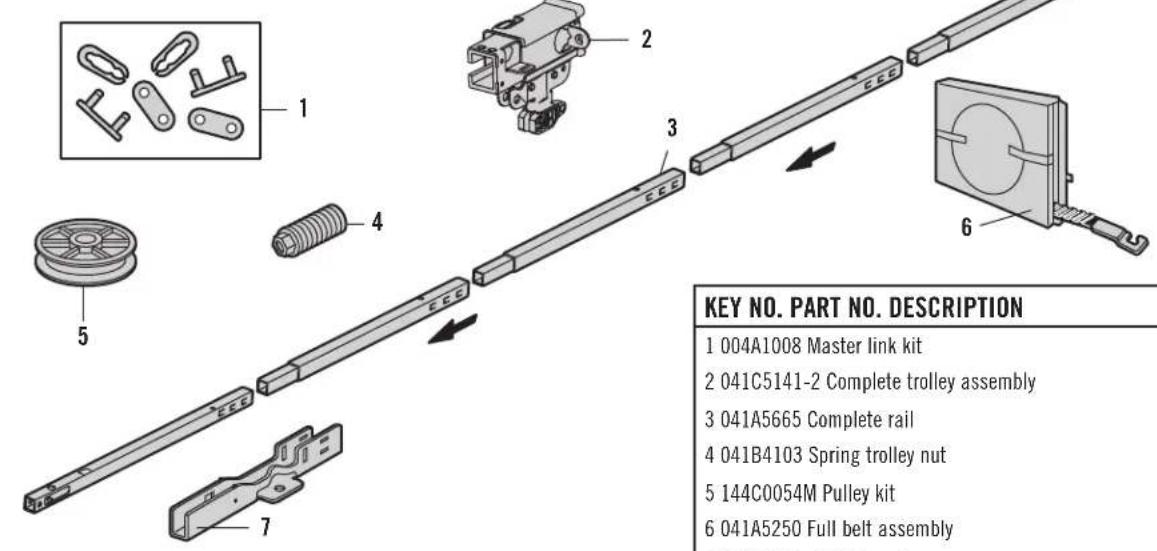
KEY NO. PART NO. DESCRIPTION
1 004A1008 Master link kit
2 041C5141-2 Complete trolley assembly
3 041A5665 Complete rail
4 041B4103 Spring trolley nut
5 144C0054M Pulley kit
6 041A5250 Full belt assembly
7 041D0598-1 "U" bracket
NOT SHOWN
041A7276 Wear pads
INSTALLATION PARTS
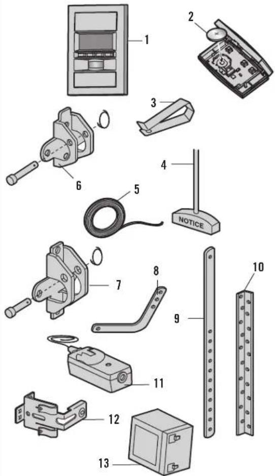
KEY NO. PART NO. DESCRIPTION
1 041A9502 LCD Door Control
2 K010A0020 3V CR2032 lithium battery
3 K029B0137 Visor clip
4 041A2828 Emergency release rope and handle assembly
5 041B4494-1 2-Conductor bell wire: white and white/red
6 041A5047-2 Header bracket with clevis pin and fastener
7 041A5047 Door bracket with clevis pin and fastener
8 041B0035B Curved door arm section
9 4178B0034B Straight door arm section
10 012B0776 Hanging bracket
11 041A5034 Safety reversing sensor kit (receiving and sending sensors) with 2-conductor bell wire attached
12 041A5266-3 Safety reversing sensor bracket
13 G4228 Battery
NOT SHOWN
K010A0016 9V battery for wireless keypad
041A7920-2 Installation hardware bag (includes hardware listed on page 9)
114-5311 Owner's manual
MOTOR UNIT ASSEMBLY PARTS
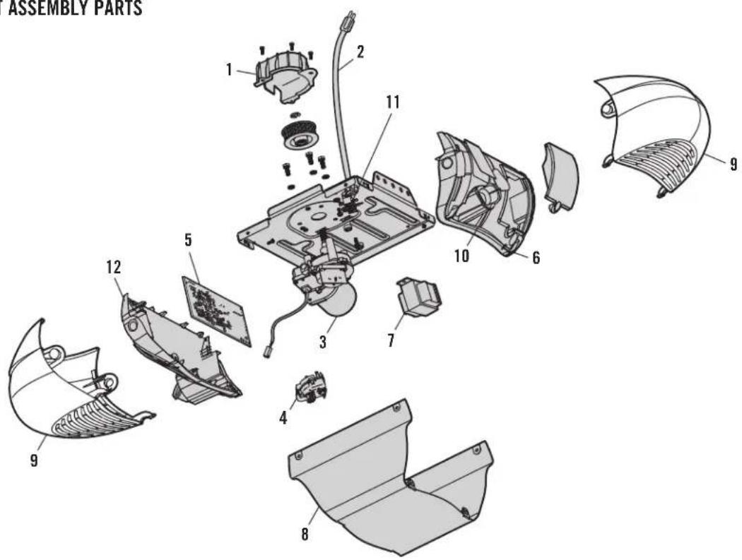
KEY NO. PART NO. DESCRIPTION KEY NO. PART NO. DESCRIPTION
1 041C1751 Sprocket and Sprocket Cover 8 041D0503-23 Cover
2 041B4245-1 Line Cord 9 108D0077M Light Lens
3 041D8006-1 Motor with Travel Module 10 041C0279 Light Socket
4 041D8071-4 Travel Module 11 041A3150 Terminal Block
5 050DCTWF Receiver Logic Board
12 041D9491 Receiver Logic Board End Panel
6 041D8385-1 End Panel with Light Socket
7 041D0277-1 Transformer
ACCESSORIES
CMXZDCG498 8 Foot (2.4 m) Rail Extension:
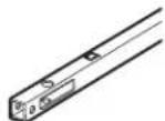
To allow an 8 foot (2.4 m) door to open fully.
CMXZDCG453 Remote Control:
fully. Works with all CRAFTSMAN openers 1993-Present. Includes visor clip.
CMXZDCG4910 10 Foot (3 m) Rail Extension:
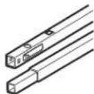
To allow a 10 foot (3 m) door to open fully.
CMXZDCG440 Wireless Keypad:
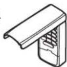
For use outside of the home to enable access to the using a 4-digit PIN. Works with ALL CRAFTSMAN opened 1993-Present.
041A5281-1 Extension Brackets:
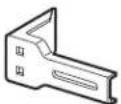
(Optional) For safety sensor installation onto the floor.
041A9502 LCD Door Control:
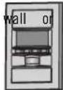
Displays temperature, time and systems diagnostics, includes a push bar to open and close the door and feature for extra security.
WARRANTY
The Chamberlain Group,® (the Seller") warrants to the first retail purchaser of this product, for the residence in which this product is originally installed, that it is free from defects in materials and/or workmanship for a specific period of time as defined below (the "Warranty Period"). The warranty period commences from the date of purchase.
| WARRANTY PERIOD | ||||
| Parts Motor Accessories | Belt Battery Backup | |||
| 5 years Lifetime 1 year | Lifetime 1 year | |||
The proper operation of this product is dependent on your compliance with the instructions regarding installation, operation, and maintenance and testing. Failure to comply strictly with those instructions will void this limited warranty in its entirety.
If, during the limited warranty period, this product appears to contain a defect covered by this limited warranty, call 1-888-331-4569, toll free, before dismantling this product. You will be advised of disassembly and shipping instructions when you call. Then send the product or component, pre-paid and insured, as directed to our service center for warranty repair. Please include a brief description of the problem and a dated proof-of-purchase receipt with any product returned for warranty repair. Products returned to Seller for warranty repair, which upon receipt by Seller are confirmed to be defective and covered by this limited warranty, will be repaired or replaced (at Seller's sole option) at no cost to you and returned pre-paid. Defective parts will be repaired or replaced with new or factory-rebuilt parts at Seller's sole option. [You are responsible for any costs incurred in removing and/or reinstalling the product or any component].
ALL IMPLIED WARRANTIES FOR THE PRODUCT, INCLUDING BUT NOT LIMITED TO ANY IMPLIED WARRANTIES OF MERCHANTABILITY AND FITNESS FOR A PARTICULAR PURPOSE, ARE LIMITED IN DURATION TO THE APPLICABLE LIMITED WARRANTY PERIOD SET FORTH ABOVE FOR THE RELATED COMPONENT(S), AND NO IMPLIED WARRANTIES WILL EXIST OR APPLY AFTER SUCH PERIOD. Some States and Provinces do not allow limitations on how long an implied warranty lasts, so the above limitation may not apply to you. THIS LIMITED WARRANTY DOES NOT COVER NON-DEFECT DAMAGE, DAMAGE CAUSED BY IMPROPER INSTALLATION, OPERATION OR CARE (INCLUDING, BUT NOT LIMITED TO ABUSE, MISUSE, FAILURE TO PROVIDE REASONABLE AND NECESSARY MAINTENANCE, UNAUTHORIZED REPAIRS OR ANY ALTERATIONS TO THIS PRODUCT), LABOR CHARGES FOR REINSTALLING A REPAIRED OR REPLACED UNIT, REPLACEMENT OF CONSUMABLE ITEMS (E.G., BATTERIES IN REMOTE CONTROL TRANSMITTERS AND LIGHT BULBS), OR UNITS INSTALLED FOR NON-RESIDENTIAL USE. THIS LIMITED WARRANTY DOES NOT COVER ANY PROBLEMS WITH, OR RELATING TO, THE GARAGE DOOR OR GARAGE DOOR HARDWARE, INCLUDING BUT NOT LIMITED TO THE DOOR SPRINGS, DOOR ROLLERS, DOOR ALIGNMENT OR HINGES. THIS LIMITED WARRANTY ALSO DOES NOT COVER ANY PROBLEMS CAUSED BY INTERFERENCE. UNDER NO CIRCUMSTANCES SHALL SELLER BE LIABLE FOR CONSEQUENTIAL, INCIDENTAL OR SPECIAL DAMAGES ARISING IN CONNECTION WITH USE, OR INABILITY TO USE, THIS PRODUCT. IN NO EVENT SHALL SELLER'S LIABILITY FOR BREACH OF WARRANTY, BREACH OF CONTRACT, NEGLIGENCE OR STRICT LIABILITY EXCEED THE COST OF THE PRODUCT COVERED HEREBY. NO PERSON IS AUTHORIZED TO ASSUME FOR US ANY OTHER LIABILITY IN CONNECTION WITH THE SALE OF THIS PRODUCT.
Some states and provinces do not allow the exclusion or limitation of consequential, incidental or special damages, so the above limitation or exclusion may not apply to you. This limited warranty gives you specific legal rights, and you may also have other rights, which vary from state to state and province to province.
AUTOMATIC GARAGE DOOR OPENER SAFETY & MAINTENANCE GUIDE
GARAGE DOOR OPENER SAFETY — AN AUTOMATIC DECISION
A garage door is the largest moving object in the home. An improperly adjusted garage door and opener can exert deadly force when the door closes – which could lead to entrapment of children or adults and subsequent injury or death.
Proper installation, operation, maintenance, and testing of the garage door and automatic opener are necessary to provide a safe, trouble-free system. Careless operation or allowing children to play with or use garage door opener controls are also dangerous situations that can lead to tragic results. A few simple precautions can protect your family and friends from potential harm. Please review the safety and maintenance tips in this guide carefully and keep it for reference. Check the operation of your garage door and opener to ensure they function in a safe and trouble-free manner. Be sure to read all Important Safety Information found in your garage door opener's manual as it provides more details and safety considerations than can be supplied with this guide.
GARAGE DOOR OPENERS ARE NOT TOYS
Discuss garage door and opener safety with your children. Explain the danger of being trapped under the door.
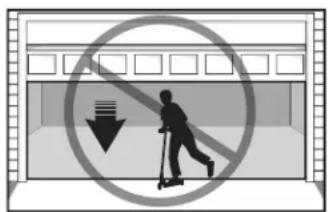
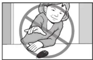
natural_image
Illustration of a person sitting with arms crossed, enclosed in a prohibition symbol (no text or symbols present)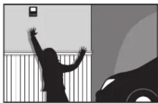
natural_image
Silhouette of a person reaching for a wall near a vehicle, with no visible text or symbols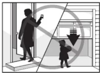
natural_image
Illustration showing a woman taking a phone to a child near a window, with a crossed-out arrow and building silhouette (no text or symbols)Stay away from a moving door.
Keep transmitters and remote controls out of reach of children. Do not let children play with or use transmitters or other remote control devices.
The wall-mounted push button should be out of reach of children, at least 5 feet from the nearest standing surface and away from all moving parts. Mount and use the button where you can clearly see the clos
Keep the door in sight until it completely closes when using the wall-mounted push button or transmitter.
ROUTINE MAINTENANCE CAN PREVENT TRAGEDIES
Make monthly inspection and testing of your garage door and opener system a part of your regular routine. Review your owner's manual for both the door and door opener. If you don't have the owner's manuals, contact the manufacturer(s) and request a copy for your specific model(s). Look for the opener model number on the back of the power unit.

WARNING - SPRINGS ARE UNDER HIGH TENSION. ONLY QUALIFIED INDIVIDUALS SHOULD ADJUST THEM.
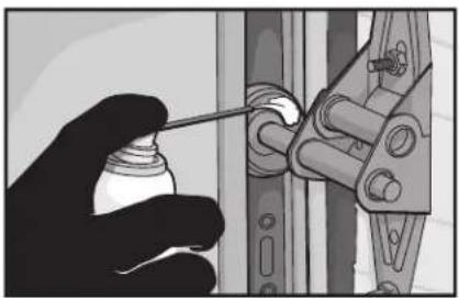
natural_image
Illustration of a hand using a tool to adjust or install a mechanical component (no text or symbols visible)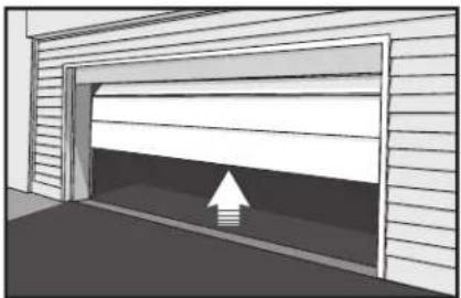
natural_image
Exterior view of a garage with an upward arrow indicating clearance (no text or symbols)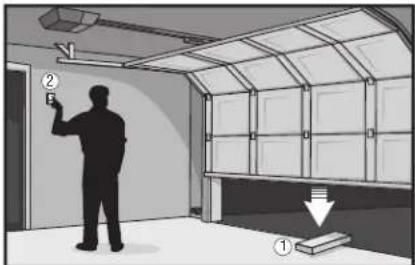
Visually check the door and installation:
- Starting with the door in the closed position, use the manual disconnect on the open disconnect the door.
- Look for signs of wear or damage on hinges, rollers, springs, and door panels.
- These parts may require periodic lubrication. Check the owner's manual for suggested maintenance.
- If any signs of damage are evident, contact a trained door systems technician for assistance.
- Verify the photoeye height is no higher than 6" from the garage floor.
Test the door for proper operation:
- Open and close the door manually using handles or suitable gripping points.
• The door should move freely and without difficulty. - The door should balance and stay partially open 3–4 feet above the floor.
- If you detect any signs of improper operation, contact a trained door systems technician for assistance.
Test the opener safety features:
- Reconnect the opener to the door using the manual disconnect and open the door.
- Place a 2x4 board flat in the path of the door (1) and try to close it (2). The door should stop when it comes in contact with the 2x4 and then reverse direction.
- Block the photoelectric sensor by waving an object in front of the sensor and attempt to close the door. The door should not close unless the wall-mounted push button is manually he operation.
- If the opener does not perform as described, contact a trained door systems technician for assistance.

DASMA
Door & Access Systems Manufacturers Association International
CRAFTSMAN®
Product questions or problems?
Customer Care Hot Line
Get answers to questions, troubleshoot problems, or order parts.
Be sure to register your product at https://www.craftsman.com/registration
natural_image
Technical line drawing of a mechanical assembly with labeled 'CRAFTSMAN.' component (no other text or symbols)natural_image
Line drawing of a person standing beside a large wall-mounted door with windows (no text or symbols)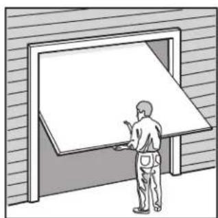
natural_image
Illustration of a person standing beside a large openboard with a blank sheet, against a textured wall background (no text or symbols)natural_image
Technical line drawing of a hexagonal bolt with threaded shaft (no text or symbols)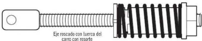
natural_image
Line drawing of a hexagonal bolt with threaded shaft (no text or symbols on the object itself)

ENSAMBLAJE PASO 4
INSTALE LA CORREA
natural_image
Technical line drawing of a mechanical device with no visible text or symbols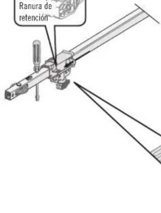
PARA ABRIR LA PUERTA MANUALMENTE
DESCONECTE EL CARRO
natural_image
Illustration of a person sitting with hands crossed, enclosed in a prohibition symbol (no text or symbols present)natural_image
Silhouette of a person reaching for a wall near a vehicle, with no visible text or symbolsnatural_image
Illustration showing a person taking a photo of a child near a window, with a crossed-out arrow and grid lines (no text or symbols)natural_image
Illustration of a hand using a spray gun to adjust or install a mechanical component (no text or symbols visible)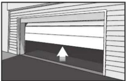
natural_image
Diagram of a garage with an upward arrow indicating clearance or storage (no text or symbols)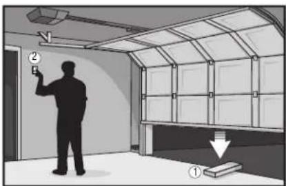
Door & Access Systems Manufacturers Association International
CRAFTSMAN®
Product questions or problems?
Customer Care Hot Line
Get answers to questions, troubleshoot problems, or order parts.
Be sure to register your product at https://www.craftsman.com/registration
- SMART GARAGE DOOR OPENER
- MODEL CMXEOCG781
- TABLE OF CONTENTS
- INTRODUCTION 3-9
- ASSEMBLY 10-13
- INSTALLATION 13-29
- ADJUSTMENT 30-32
- BATTERY BACKUP 33
- myQ® SMARTPHONE CONTROL 34
- OPERATION 35-41
- TROUBLESHOOTING 42-43
- REPAIR PARTS 44-45
- ACCESSORIES 46
- WARRANTY 46
- AUTOMATIC GARAGE DOOR OPENER SAFETY & MAINTENANCE GUIDE 47-48
- INTRODUCTION
- SAFETY SYMBOL REVIEW AND SIGNAL WORD REVIEW
- UNATTENDED OPERATION
- PREPARING YOUR GARAGE DOOR
- WARNING
- CAUTION
- TEST THE W# SIGNAL STRENGTH IN YOUR GARAGE
- Check Signal Strength. If you see:
- Visit support.chamberlaingroup.com for more details
- TOOLS NEEDED
- PLANNING
- PLANNING (CONTINUED)
- ONE-PIECE DOOR INSTALLATIONS
- CARTON INVENTORY
- HARDWARE INVENTORY
- ASSEMBLY STEP 1
- ASSEMBLE THE RAIL AND INSTALL THE TROLLEY
- ASSEMBLY STEP 2
- FASTEN THE RAIL TO THE MOTOR UNIT
- ASSEMBLY STEP 3
- INSTALL THE IDLER PULLEY
- ASSEMBLY STEP 4
- INSTALL THE BELT
- ASSEMBLY STEP 5
- TIGHTEN THE BELT
- ASSEMBLY STEP 6
- INSTALL THE SPROCKET COVER
- INSTALLATION
- IMPORTANT INSTALLATION INSTRUCTIONS
- To reduce the risk of SEVERE INJURY or DEATH:
- INSTALLATION STEP 1
- DETERMINE THE HEADER BRACKET LOCATION
- INSTALLATION STEP 2
- INSTALL THE HEADER BRACKET
- WALL HEADER BRACKET INSTALLATION
- CEILING HEADER BRACKET INSTALLATION
- INSTALLATION STEP 3
- ATTACH THE RAIL TO THE HEADER BRACKET
- INSTALLATION STEP 4
- POSITION THE OPENER
- SECTIONAL DOOR OR ONE-PIECE DOOR WITH TRACK
- ONE-PIECE DOOR WITHOUT TRACK
- INSTALLATION STEP 5
- HANG THE OPENER
- INSTALLATION STEP 6
- INSTALL THE LIGHTS
- INSTALLATION STEP 7
- ATTACH THE EMERGENCY RELEASE ROPE AND HANDLE
- INSTALLATION STEP 8
- FASTEN THE DOOR BRACKET
- SECTIONAL DOORS
- FASTEN THE DOOR BRACKET (CONTINUED)
- ONE-PIECE DOORS
- INSTALLATION STEP 9
- CONNECT DOOR ARM TO TROLLEY
- SECTIONAL DOORS ONLY
- Hole alignment alternative (Figure 3):
- CONNECT DOOR ARM TO TROLLEY (CONTINUED)
- ALL ONE-PIECE DOORS
- INSTALLATION STEP 10
- ATTACH THE WARNING LABELS
- INSTALLATION STEP 11
- INSTALL THE LCD DOOR CONTROL
- WIRE THE DOOR CONTROL (FIGURE 1)
- MOUNT THE DOOR CONTROL (FIGURE 2)
- WIRE THE DOOR CONTROL TO THE GARAGE DOOR OPENER (FIGURE 3)
- INSTALLATION STEP 12
- INSTALL THE SAFETY REVERSAL SYSTEM (CONTINUED)
- INSTALLING THE BRACKETS
- Garage door track installation (preferred):
- Wall installation (Figures 2 and 3):
- Floor installation (Figure 4):
- Mounting:
- Option A - Installation Without Pre-Wiring:
- Option B - Pre-Wired Installation:
- CONNECT TO GARAGE DOOR OPENER:
- INSTALLATION STEP 13
- ELECTRICAL REQUIREMENTS
- INSTALLATION STEP 14
- ALIGNING THE SAFETY REVERSING SENSORS
- IF THE AMBER LED ON THE SENDING SENSOR IS NOT GLOWING:
- IF THE GREEN LED ON THE RECEIVING SENSOR IS NOT GLOWING:
- ADJUSTMENT
- ONE-PIECE DOORS ONLY
- PROGRAMMING BUTTONS
- ADJUSTMENT STEP 1
- PROGRAM THE TRAVEL
- ADJUSTMENT STEP 2
- ADJUST
- IMPORTANT SAFETY CHECK:
- ADJUSTMENT STEP 3
- TEST THE SAFETY REVERSING SENSORS
- BATTERY BACKUP
- INSTALL THE BATTERY
- TEST THE BATTERY
- BATTERY STATUS LED
- GREEN LED:
- CHARGE THE BATTERY
- ORANGE LED:
- RED LED:
- myQ® SMARTPHONE CONTROL
- CONNECT WITH YOUR SMARTPHONE
- YOU WILL NEED:
- DOWNLOAD THE @myAPP TO SET UP AN ACCOUNT AND CONNECT
- NOTES:
- OPERATION
- IMPORTANT SAFETY INSTRUCTIONS
- SAVE THESE INSTRUCTIONS.
- FEATURES
- TIMER-TO-CLOSE (DO NOT ENABLE ON ONE-PIECE DOORS)
- REMOTE CONTROLS AND DOOR CONTROLS
- ENERGY GREATE CONSERVATION
- LIGHTS
- USING YOUR GARAGE DOOR OPENER
- LCD DOOR CONTROL
- SYNCHRONIZE THE DOOR CONTROL
- PUSH BAR
- LIGHT BUTTON
- NAVIGATION BUTTONS
- SCREEN
- LEARN the device will activate the
- LOCK
- TIMER-TO-CLOSE (TTC)
- AUTOMATIC LIGHT
- Motion Sensor
- Light Feature
- LCD DOOR CONTROL (CONTINUED)
- SCREEN AND MENU NAVIGATION
- SETTINGS
- PROGRAMMING
- TO ERASE THE MEMORY
- ERASE ALL REMOTE CONTROLS AND KEYLESS ENTRIES
- ERASE THE CONNECTION FROM GARAGE DOOR OPENER TO
- WI-FI NETWORK
- ERASE ALL DEVICES (INCLUDING ENAPCLED ACCESSORIES)
- TO OPEN THE DOOR MANUALLY
- THE REMOTE CONTROL BATTERY
- CARE OF YOUR OPENER
- MAINTENANCE SCHEDULE
- Every month
- Every year
- TROUBLESHOOTING
- DIAGNOSTIC CHART
- My garage door opener beeps every 30 seconds:
- My remote control will not activate the garage door:
- REPAIR PARTS
- KEY NO. PART NO. DESCRIPTION
- NOT SHOWN
- KEY NO. PART NO. DESCRIPTION KEY NO. PART NO. DESCRIPTION
- ACCESSORIES
- WARRANTY
- AUTOMATIC GARAGE DOOR OPENER SAFETY & MAINTENANCE GUIDE
- GARAGE DOOR OPENERS ARE NOT TOYS
- ROUTINE MAINTENANCE CAN PREVENT TRAGEDIES
- CRAFTSMAN®
- ENSAMBLAJE PASO 4
- INSTALE LA CORREA
- PARA ABRIR LA PUERTA MANUALMENTE
- DESCONECTE EL CARRO
Brand : Craftsman
Model : CMXEOCG781
Category : Garage door opener