
57953 - Garage door opener Craftsman - Free user manual and instructions
Find the device manual for free 57953 Craftsman in PDF.


| Product Type | Garage Door Opener |
| Brand | Craftsman |
| Model | 57953 |
| Drive Type | Chain Drive |
| Motor Power | 1/2 HP |
| Voltage | 120V AC, 60Hz |
| Dimensions (H x W x D) | 12 x 10 x 8 inches |
| Weight | 18 lbs |
| Remote Control Frequency | 315 MHz |
| Number of Remotes Included | 2 |
| Safety Sensors | Photoelectric sensors (auto-reverse) |
| Manual Release | Emergency release cord |
| Lighting | Integrated 60W bulb |
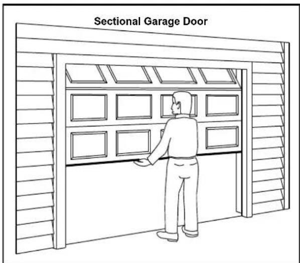
| Compatible Door Types | Sectional or one-piece doors |
| Maximum Door Weight | 250 lbs |
| Maximum Door Height | 7 feet |
| Warranty | 1 year limited |
| Maintenance | Lubricate moving parts annually; check safety sensors monthly |
| Spare Parts Availability | Remote controls, sensors, motor assembly available |
| Repair Service | DIY with manual or professional service |
Frequently Asked Questions - 57953 Craftsman
User questions about 57953 Craftsman
0 question about this device. Answer the ones you know or ask your own.
Ask a new question about this device
Download the instructions for your Garage door opener in PDF format for free! Find your manual 57953 - Craftsman and take your electronic device back in hand. On this page are published all the documents necessary for the use of your device. 57953 by Craftsman.
USER MANUAL 57953 Craftsman
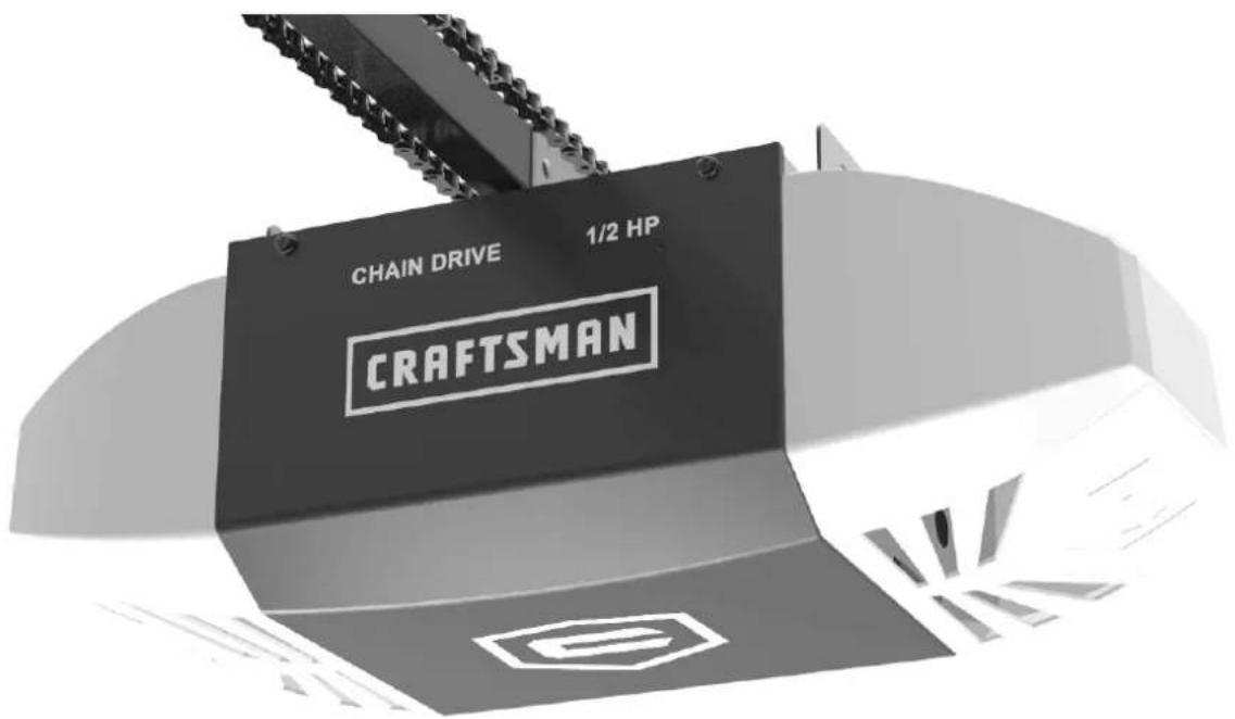
GARAGE DOOR OPENER Abridor de puerta de cochera MODEL/MODELO 200.57953
For Residential Use Only Sólo para uso residencial
Read and follow all safety rules and operating instructions before first use of this product.
Fasten the manual near the garage door after installation.
Periodic checks of the opener are required to ensure safe operation.
DO NOT install on a one-piece door.
Preparation / Tools Required 4
Assembly
Rail and Trolley Assembly 5
Installing the Cable and Chain 6
Important Installation Instructions 7
Mounting Header Bracket 8
Installation
Attaching Rail to Header Bracket and Mounting Door Bracket 9
Mounting Opener to Ceiling 10
Attaching Door Arms 11
Installing Light and Emergency Release Handle 12
Wiring
Wiring Instructions 13
Connecting Photo Eye Safety System 14
Connecting Door Control Console 15
Connecting Power 16
Adjustment
Aligning the Photo Eye Safety System 16
Travel Limit Adjustment 17
Force Adjustment 18
Final Adjustment and Testing 19
Operation
Programming 3-Button Remote 20
Programming Keyless Entry Pad 21
Important Safety Instructions 22
Operating the Opener 23-24
Maintenance 25
Troubleshooting 25
Repair Parts and Service
Rail Assembly Parts / Installation Parts / Accessories 26
Opener Assembly parts 27
Warranty 28
Symbols and Icons

WARNING
READ WARNINGS CAREFULLY to prevent SERIOUS INJURY or DEATH caused by electrocution or mechanical hazard.
DO NOT connect power
Please connect power
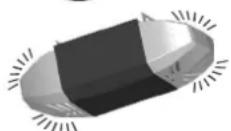
Courtesy light turns on/flashes with audible 'click'. (If light bulb is not installed, 'click' represents the light)
Installation hardware
Inventory
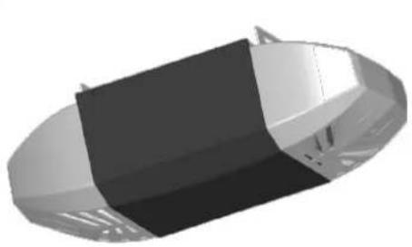
natural_image
3D rendered illustration of a capsule-shaped object with black and white sections (no text or symbols)Opener Unit + Light Lens Cover
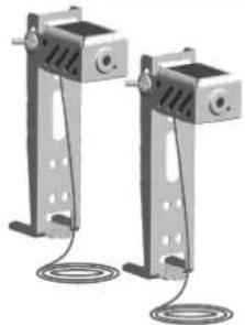
natural_image
Two identical metal frame holders with circular base connections, no text or symbols visiblePhoto Eye Safety System
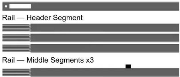
Rail — End Segment with Trolley Stop Bolt
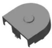
Sprocket Cover
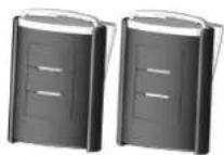
Two 3-Button Mini Remotes
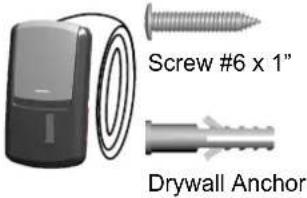
Door Control Console
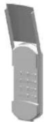
Wireless Keyless Entry Keypad
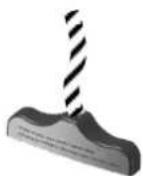
Emergency Release Handle + Rope
Literature + Safety Labels
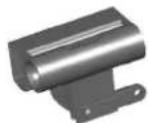
Trolley
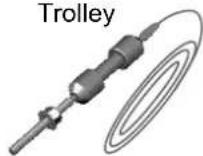
Trolley Shaft and Cable
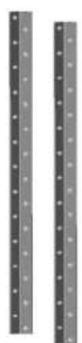
Hanging Brackets
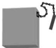
Chain
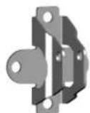
Door Bracket
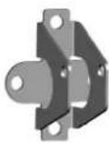
Header Bracket

Pulley
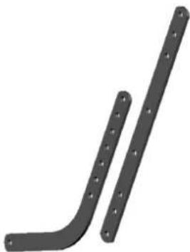
natural_image
Two black metal pipe fittings with bolt holes, no text or symbols presentDoor Arms
INSTALLATION HARDWARE, LOCATED IN HARDWARE BAG (SHOWN IN ACTUAL SIZE)
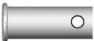
x 2
Clevis Pin — Door arms 5/16" x 1"
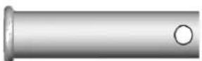
x 1
Clevis Pin — Header Bracket 5/16" x 1-1/2"
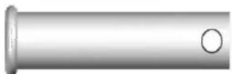
x 1
Clevis Pin — Pulley 3/8" x 1-3/4"
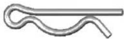
x 4
Hitch Pin — Locking Clevis Pins
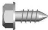
x 2
Self-Threading Screw 1/4" x 5/8"
Door Bracket
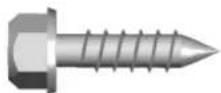
x 4
Lag Screw #12 x 1"— Photo Eye System
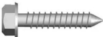
natural_image
Close-up of a metallic hexagonal bolt with threaded shaft (no text or symbols visible)x 4
Lag Screw 5/16" x 1-1/2"
— Header Bracket / Mounting Opener
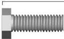
x 4
Bolt 5/16" x 1"
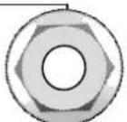
x 4
5/16" Flange Nut
— Door arms / Mounting Opener

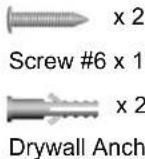
Screw #6 x 1-1/4" - Push Button
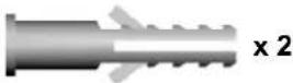
Drywall Anchor - Push Button
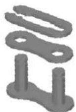
x 1
Master Link Set
—Trolley Shaft
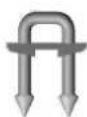
x 30
Insulated Staples — Securing wires

WARNING
To prevent SERIOUS INJURY or DEATH:
- Before beginning installation of the opener please complete the following test to ensure that your door is balanced and in good working condition.
- A poorly balanced door can cause serious injury and damage to the opener.
- Always have a qualified garage door service technician make any required adjustments and/or repairs to your door before proceeding with installation.
- DISABLE ALL LOCKS and REMOVE ALL ROPES connected to the garage door BEFORE installing and/or operating the opener.
To prevent damage to the door and opener:
- DO NOT connect power until instructed.
- Operate this opener with AC 120V/60Hz power supply ONLY.
DO NOT REUSE PARTS FROM ANOTHER BRAND OF OPENER!!!
BEFORE beginning Installation:
- Disable locks and remove all ropes connected to the garage door.
- Perform the following door test to ensure your door is balanced and in good working condition.
To Test Your Garage Door
- Raise and lower the door to check if there is any sticking or binding.
- Check for loose hinges, damaged rollers, frayed cables and damaged or broken springs.
- Lift the door approximately halfway and release. The door should stay at the point under proper spring tension.
Call a qualified garage door service technician if your door binds, sticks or is unbalanced.
Tools Required
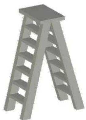
natural_image
3D illustration of a gray ladder-like structure with no text or symbolsStep Ladder
Level
Pencil
Screwdriver
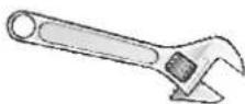
Adjustable Wrench
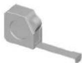
Tape Measure
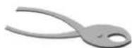
Pliers
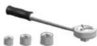
Ratchet with
5/16", 7/16" and 1/2" sockets
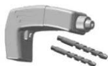
Drill, 3/16" and 5/16" Drill Bits
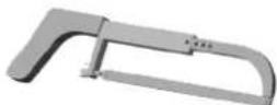
Hack Saw
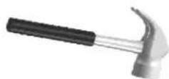
Hammer
To Assemble Rail and Opener
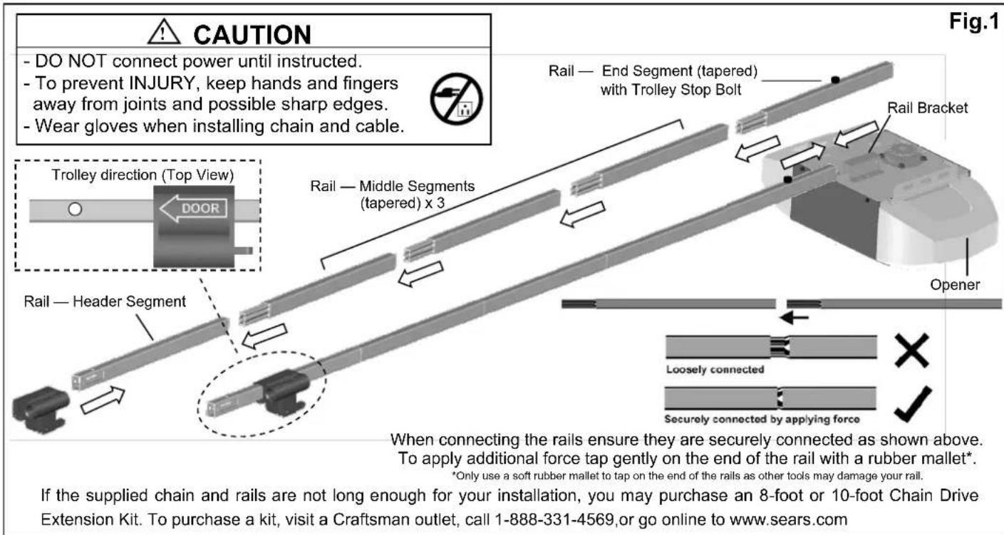
- Prepare the rails as shown in Fig.1.
- Connect the rails starting with the header segment. Insert the tapered ends into open ends, apply any additional force necessary by tapping the rail on padded flooring. Ensure the end segment has trolley stop bolt facing up. Make sure the rails are securely joined together as shown.
- Slide the trolley onto the rail from the header segment. Make sure the arrow is pointing towards the door as shown in Fig.1.
- Connect the rail assembly to the rail bracket on the opener.
To Assemble the Header Section of Rail
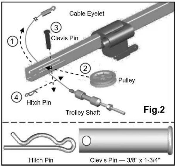
Follow steps shown in Fig.2:
- Remove the "trolley shaft and cable" from the chain carton and lay it beside the rail assembly. Hold cable eyelet on the end of cable and thread about 20" (50cm) through the slot on the Header Segment of the rail.
- Insert the pulley into the opening while the cable is hanging.
- Secure the pulley by inserting the 3/8" x 1-3/4" clevis pin through the top of the rail.
- Lock the clevis pin with a hitch pin. Rotate the pulley to ensure it spins smoothly.
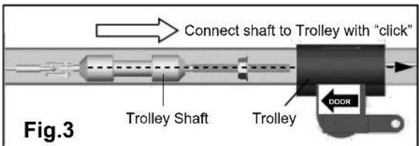
Refer to Fig.3 to connect the trolley shaft to the trolley. Slide both the trolley shaft and trolley towards each other. A "click" will be heard when they are connected.
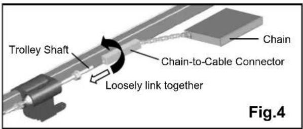
To Link Cable with Chain
Refer to Fig.4. Place the chain carton beside the rail, hold the "chain to cable connector" and pull about 8" (20cm) of chain from the box. Thread the chain to cable connector onto the trolley shaft so that they are loosely linked together.

WARNING
To prevent SERIOUS INJURY:
- DO NOT connect power until instructed.
- Keep hands and fingers clear from sprocket during operation.
- Wear gloves when installing chain and cable.
- Keep hands and fingers away from joints and possible sharp edges.
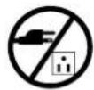
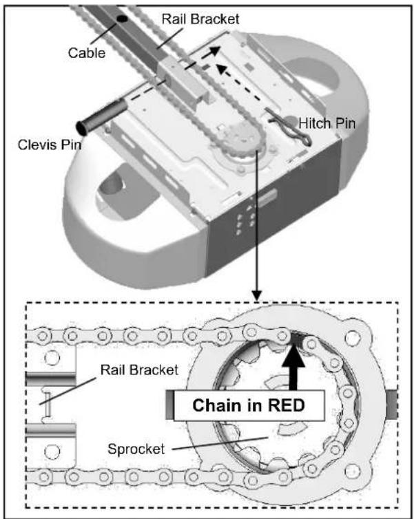
Fig.1
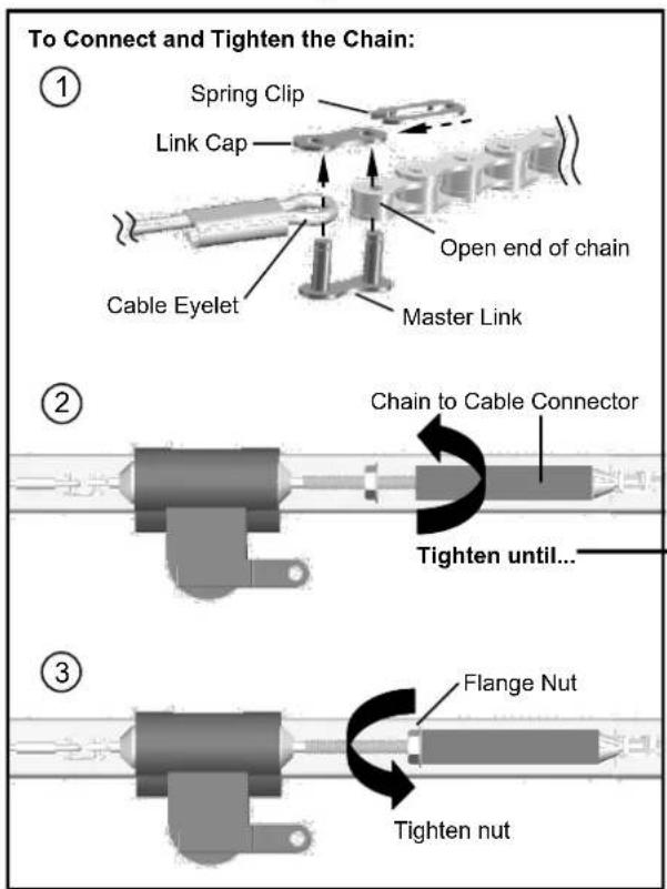
Fig.2
To Install Chain
- Pull the remaining chain along the rail toward the opener.
- A segment of chain marked in RED will be seen. Place this segment in the approximate location on the sprocket as shown in Fig.1.
- When the chain is aligned properly around the sprocket, pull the chain-to-cable connector towards the trolley shaft.
Follow steps shown in Fig.2 to connect & tighten the chain:
- Align the open end of the chain to the cable eyelet and connect together using the master link set.
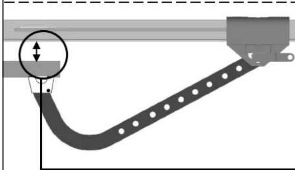
- Turn the chain-to-cable connector on the trolley shaft until the chain is about 1/4" (6mm) above the base of the rail. Compare with the illustration below.
- Tighten the flange nut on trolley shaft against the chain-to-cable connector.
When the chain and cable are tightened around the rail and sprocket on the opener, check and make sure the chain is properly aligned and not twisted. Attach the sprocket cover to the opener as shown in Fig.3.
Notice
During operation, it is normal for the chain to appear loose when the door is closed. If the chain returns to the position as shown below when the door is opened, the chain is adjusted properly. DO NOT re-tighten the chain.
When performing maintenance, always PULL the emergency release to DISCONNECT the door from opener before adjusting the chain.
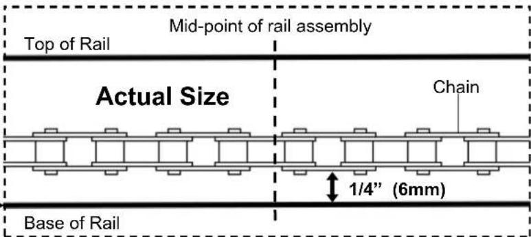
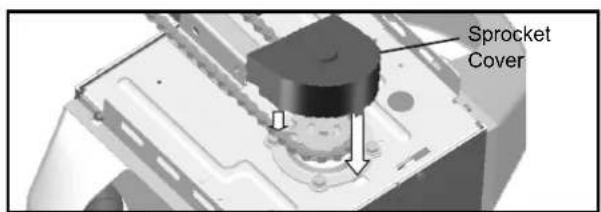
Fig.3
Important Installation Instructions
IMPORTANT INSTALLATION INSTRUCTIONS
WARNING
To reduce the risk of severe injury or death:
- READ AND FOLLOW ALL INSTALLATION INSTRUCTIONS.
- Install only on a properly balanced garage door. An improperly balanced door has the potential to inflict severe injury. Have a qualified service person make repairs to cables, spring assemblies, and other hardware before installing the opener.
- Remove all ropes and remove or make inoperative all locks connected to the garage door before installing opener.
- Where possible, install the door opener 7 feet or more above the floor. For products having an emergency release, mount the emergency release within reach, but at least 6 feet above the floor and avoiding contact with vehicles to avoid accidental release.
- Do not connect the opener to source of power until instructed to do so.
- Locate the push button: (a) within sight of door, (b) at a minimum height of 5 feet so small children are not able to reach it, and (c) away from all moving parts of the door.
- Install the Entrapment Warning Label next to the wall-mount push button in a prominent location. In case the adhesive does not adhere on the surface, the label should be attached to the surface by mechanical means.
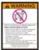
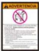
Place entrapment warning label on wall next to garage door control.
8. After installing the opener, the door must reverse when it contacts a 1-1/2-inch high object (or a 2 by 4 board laid flat) on the floor.

WARNING
To prevent SERIOUS INJURY:
- DO NOT connect power until instructed.
- The header bracket MUST be SECURELY fastened to the structural support on the mounting wall or ceiling, otherwise the door may not reverse when required. DO NOT install the header bracket over drywall.
- Concrete anchors MUST be used when mounting the header bracket into masonry.
- NEVER try to loosen, move or adjust garage door springs, cables, pulleys, brackets, or hardware.
- Contact a qualified garage door service technician if your door binds, sticks or is unbalanced. An unbalanced door might not reverse when required.
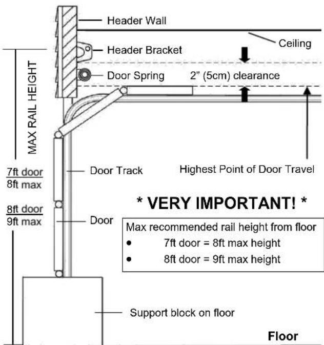
Fig.1
To Install Header Bracket
Note: Installation procedures may vary according to door type.
- While inside your garage, close the door and mark the vertical centerline of the garage door. Extend the line onto the header wall above the door spring.
- Open the door to the highest point of travel. Mark a line on the header wall 2" (5cm) above the highest point of travel.
Note: DO NOT install the header bracket over drywall. In some installations, it may be necessary to install a 2x4 across two wall studs to create a suitable location for the header bracket.
If installing into masonry, use concrete anchors (not provided).
Wall-Mounting
As shown in Fig.2, place the header bracket on the vertical centerline in direction shown.
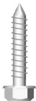
Mark and drill two 3/16" holes. Fasten the header bracket securely to a structural support using two 5/16" x 1-1/2" lag screws.
Alternative Ceiling-Mounting
Ceiling-mounting is suggested ONLY when clearance is minimal.
Extend the vertical centerline onto the ceiling as shown in Fig.3. Center the header bracket on the vertical mark, no more than 6" (15cm) from the header wall. Mark and drill holes to fasten the header bracket securely to a structural support.
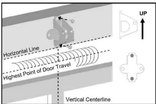
Fig.2 (Wall-Mounting)
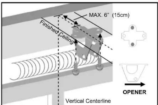
Fig.3 (Ceiling-Mounting)
natural_image
3D illustration of a hexagonal bolt with threaded shaft and hex nut (no text or symbols)Lag Screw 5/16" x 1-1/2"
Attaching Rail to Header Bracket and Mounting Door Bracket

CAUTION
To prevent SERIOUS INJURY:
- DO NOT connect power until instructed.
- Horizontal and vertical REINFORCEMENT is needed for fiberglass, aluminum or lightweight steel garage doors BEFORE installing the door bracket. Contact your door manufacturer for reinforcement options.

Fig.1
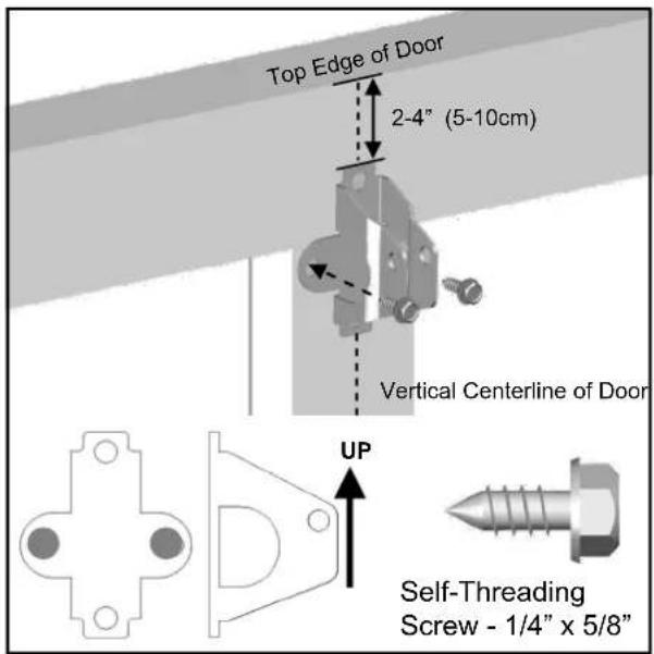
Fig.2
To Attach the Opener to the Header Bracket
- As shown in Fig.1, use the packaging carton as temporary support for the opener. Place the opener on carton to prevent damage.
- Align the mounting hole on the header rail to the mounting hole on the Header Bracket.
- Connect the header rail and the door bracket together with a 5/16" x 1-1/2" clevis pin and lock it in place with a hitch pin.
To mount the Door Bracket
Note: Some door reinforcement kits may provide direct attachment of the door arm to the reinforcement bracket. If you have a door reinforcement bracket with this option, skip this step and proceed with the next step "mounting opener to ceiling".
- Position the door bracket on the centerline of the door approximately 2" - 4" (5-10cm) below the top edge of the door, as shown in Fig.2.
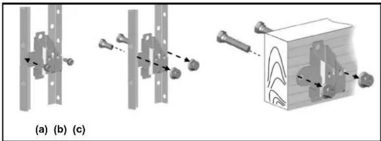
- Depending on the construction of your door, install using one of the steps shown if Fig. 3 below:
For lightweight steel doors, with factory equipped vertical steel reinforcement and horizontal strut.
(a) Mark and drill two 3/16" holes. Make sure not to drill through the garage door. Secure the door bracket with two 1/4" x 5/8" self-threading screws (provided) as shown in Fig.3(a).
(b) Alternative installation: Drill two 5/16" holes through the door. Secure the door bracket using two 5/16" bolts, lock washers and nuts (not provided) as shown in Fig.3(b). The length of bolts will depend on the thickness of your door.
Wood door
(c) Mark and drill two 5/16" holes through the garage door. Secure the door bracket using two 5/16" carriage bolts, washers and nuts (not provided) as shown in Fig.3(c). The length of bolts will depend on the thickness of your door.
Note: DO NOT use Self-Threading Screws on a wood door.
natural_image
Diagram showing three mechanical assembly steps: (a) fixed supports, (b) clamping joints, and (c) assembled with a block with arrows indicating motion.Fig.3

WARNING
To prevent SERIOUS INJURY or DEATH:
- DO NOT connect power until instructed.
- Install the opener at least 7 feet (2.13m) above the floor.
- Fasten the opener SECURELY to STRUCTURAL SUPPORTS of the garage to prevent falling.
- If installing brackets to masonry, concrete anchors (not provided) MUST be used.
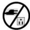
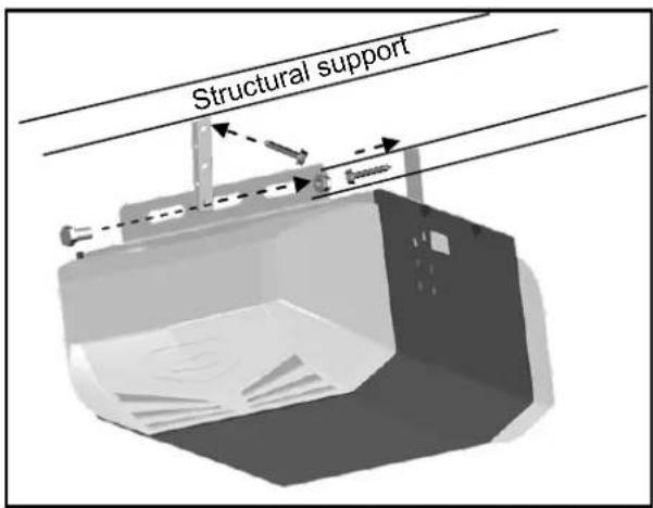
Fig.1
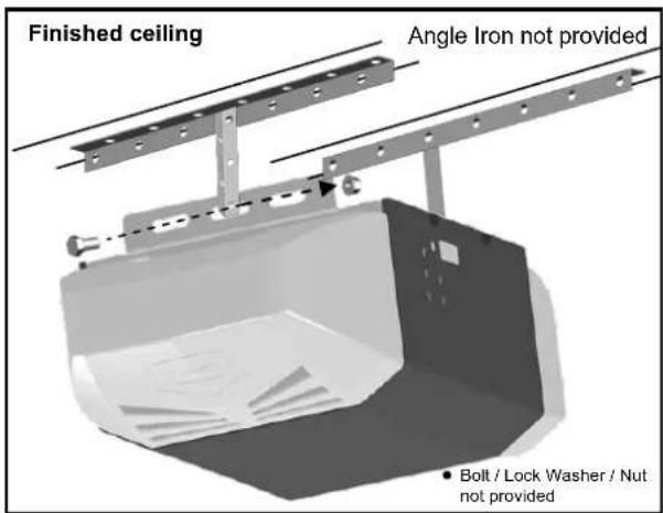
Fig.2
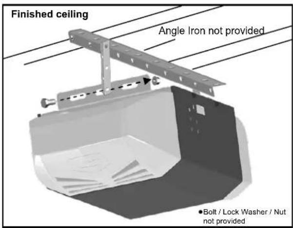
Fig.3
To Mount the Opener to Ceiling
The three most common installation options are shown in Fig.1-3.
Fig.1 shows mounting the opener directly to structural support on the ceiling. Fig.2 and 3 show mounting on a finished ceiling, with heavy duty angle iron ^ . ^ (angle iron not included)
Determine the mounting option that works best for your application and follow installation steps below:
- Raise the opener and rail assembly and temporarily place it on a stepladder.
- Position the opener and rail assembly so that it is aligned to the center line of the garage door. If the header bracket was mounted off center, align the opener with the header bracket.
- Measure the distance from each side of the opener to the structural supports.
- Cut both hanging brackets to appropriate length.
- Drill 3/16" holes in the structural supports.
- Secure one end of each of the hanging brackets to the structural supports using 5/16" x1-1/2" lag screws (provided).
- Secure the opener to the hanging brackets and secure each side with a 5/16" x 1" bolt and flange nut (provided).
- Move the door manually to check clearance between highest point of travel of the door and rail. If the door hits the rail, raise the header bracket or adjust the mounting of opener.
- Remove the ladder ONLY when the opener is securely mounted to the structural supports.
Fastening Hanging Brackets to structural supports
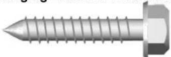
natural_image
Close-up of a metallic screw with threaded shaft and hexagonal end (no text or symbols)Lag Screw 5/16" x 1-1/2"
Securing Opener to Hanging Brackets
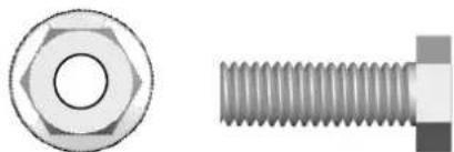
natural_image
Two technical illustrations of a hexagonal bolt and a threaded screw (no text or symbols)Bolt 5/16" x 1" Flange Nut
WARNING
To prevent SERIOUS INJURY:
- DO NOT connect power until instructed.
- Keep hands and fingers away from the sprocket during operation.
- Wear gloves when installing chain and cable.
- Keep hands and fingers away from joints and possible sharp edges.

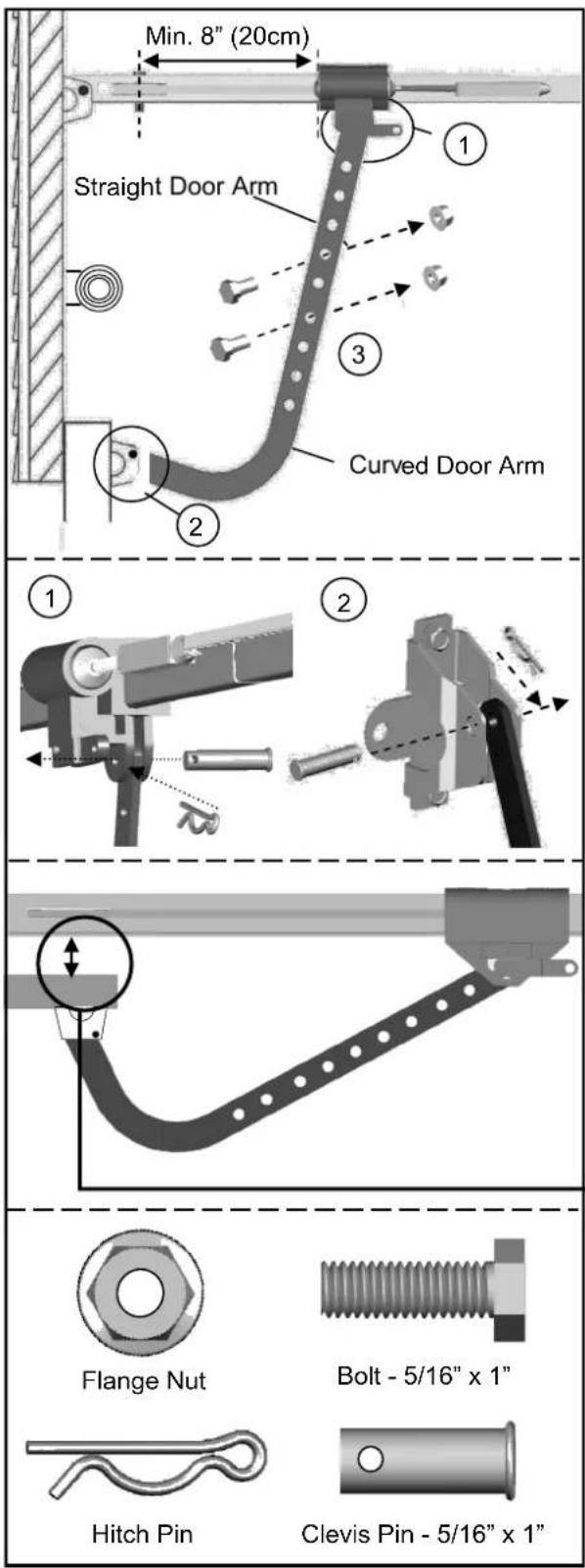
Fig.1
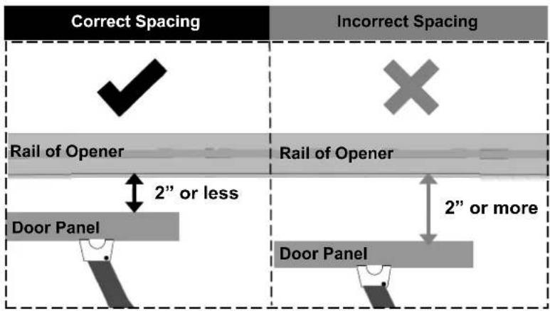
NOTE: The trolley must be a minimum of 8" (20cm) away from the pulley.
To Connect Door Arm
Follow the steps shown in Fig. 1
- Fasten the straight door arm to the trolley with a 5/16" x 1" clevis pin and lock it with a hitch pin.
- Fasten the curved door arm to the door bracket with 5/16" x 1" clevis pin and lock it with a hitch pin.
- To connect the door arms together, choose two pairs of holes which are as far apart as possible. Fasten the arms using two 5/16" x 1" bolts and flange nuts.
Installing Light and Emergency Release Handle

WARNING
To prevent SERIOUS INJURY or DEATH from electrocution:
- Disconnect power cord before installing/replacing light bulb.
To prevent possible OVERHEATING or damage to opener: - Use ONLY A19 (E26) incandescent bulbs* (100W max.).
- DO NOT use short neck or specialty light bulbs.
- DO NOT use halogen bulbs.
* CFL or LED light bulbs will work but may interfere with hand-held remotes.
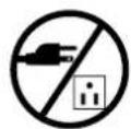
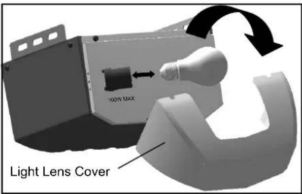
Fig. 1
To install the light:
- Insert screw driver between lens and the cover at the detents, pry and pull the light lens cover from the top and detach it from the opener.
- Install a standard A19 (E26) 100 watt maximum light bulb.
- Re-attach the light lens cover.
Notice
When replacing the light bulb, make sure the bulb on the opener has cooled down to prevent injury.

WARNING
To prevent SERIOUS INJURY or DEATH from a falling garage door:
- In case of power failure or door obstruction, PULL EMERGENCY HANDLE to release door from opener.
- When emergency release is in the released position, the door can be operated manually.
- To reconnect, flip the lever on the trolley towards opener, back to connect position, it will reconnect automatically upon pressing push button or remote control.
- DO NOT use emergency handle to pull the door open or closed.
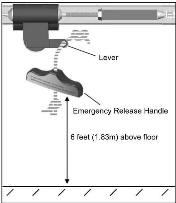
Fig. 2
To attach the Emergency Release Handle:
- Thread one end of the rope through the hole of the emergency release handle and secure with an overhand knot.
- Thread the other end of the rope through the hole in the trolley lever.
- Measure the rope length so that the handle is 6 feet (183cm) above the floor and is clear from the top of your vehicle. Secure with an overhand knot.
\* VERY IMPORTANT! \*
Emergency release handle must clear all vehicles. An emergency release handle set too low may get caught by the vehicle and cause damage to the door and opener. Measure from the floor to the top of your vehicle and set the emergency release handle above this measurement.
Wiring Instructions

WARNING
To prevent SERIOUS INJURY or DEATH from electrocution:
- Power MUST NOT be connected until instructed.
- NO exposed part of the wire should be visible outside of the terminal for proper connection.
* VERY IMPORTANT! *
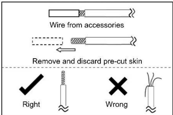
Fig. 1
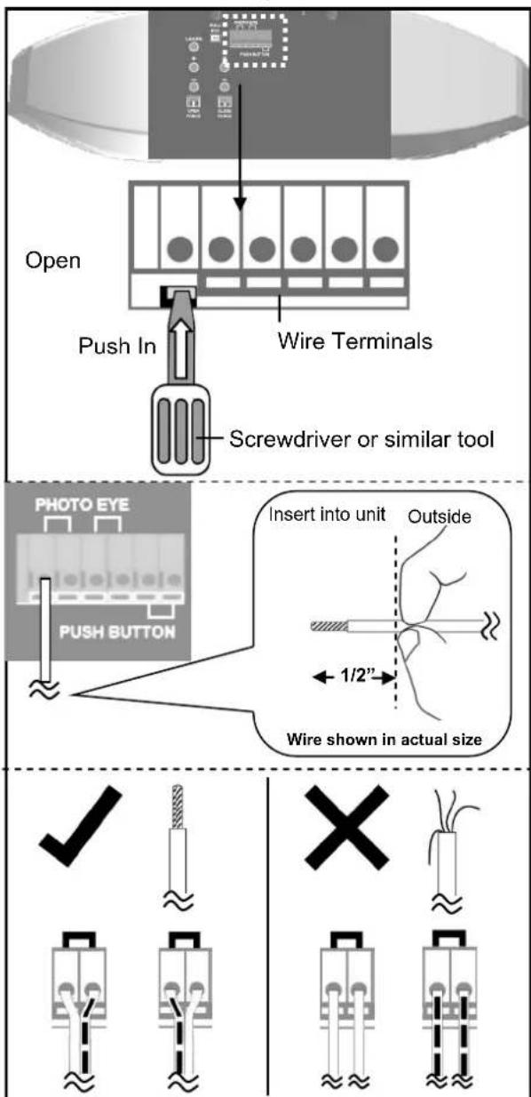
Fig. 2
In the following section, the photo eye safety system and push button will be connected to the opener. Please read and understand the wiring instructions before connecting wires.
- Remove the pre-cut skin on the open end of wire from accessories. Wires MUST NOT be frayed. Wires must be connected as shown in Fig.1.
- To connect a wire to an assigned terminal, use a small "flat head" screwdriver to push in the orange tab on the Wire terminal as shown in Fig.2.
- Insert approximately 1/2" (13mm) of the wire into the terminal while pushing in the tab as shown in Fig.2.
- Each accessory requires a pair of terminals. Each pair of terminals MUST be connected with one white wire and one striped wire (non-polarized) from the SAME accessory as shown in Fig.2.
- Check for proper connection by gently pulling on the wire. The wire should not come out of the terminal. NO exposed part of the wire should be visible outside of the terminal.
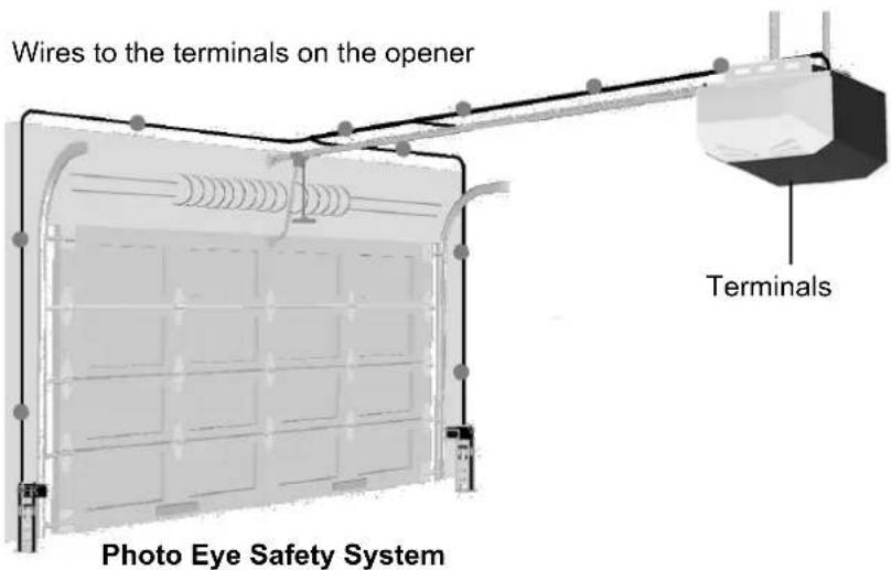
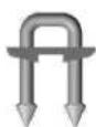
- Use the insulated staples provided to secure the wires to the wall and/or ceiling. Be careful not to damage the wires while securing the staples.

Suggested placement of insulated staples
Connecting Photo Eye Safety System

WARNING
To prevent SERIOUS INJURY or DEATH from electrocution:
- Power MUST NOT be connected BEFORE photo eye safety system is connected and aligned.
- The opener will not operate until the photo eye safety system is properly connected and aligned.
- Install the photo eyes NO higher than 6" (15cm) above the floor.
No part of garage door or other objects should obstruct the photo eye safety system during door-closing.
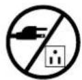
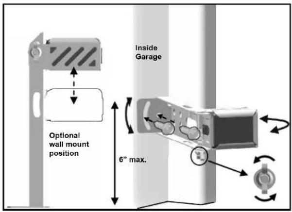
Fig. 1 (Wall Mount)
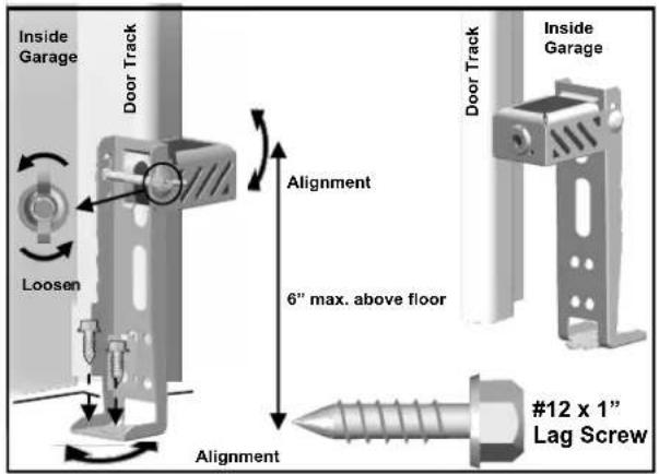
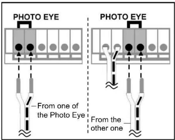
Fig. 3
About the Photo Eye Safety System
The photo eye safety system provides protection against entrapment while the door is closing. When properly connected and aligned, the emitter photo eye emits an invisible infrared light beam while the sensor photo eye monitors that beam.
If the beam is obstructed during door-closing, the entrapment protection will be triggered and the door will stop and reverse to the open position. The courtesy light will flash for 30 seconds indicating an obstruction.
Installing The Photo Eye Safety System
Wall-mounting
- Place the photo eyes facing each other on each side of the garage door. Position the sensors so they are no higher than 6" (15cm) above the floor, as shown in Fig.1.
- Drill 3/16" holes using the mounting holes on the bracket as a template. Secure with #12 x 1" lag screws (provided).
- Be sure brackets, when mounted, are NOT in contact with the door track.
- If necessary use the optional wall-mount position (Fig.1) to better fit your door-track and improve obstacle avoidance. To adjust the position, loosen the wing nut, disassemble the bracket and move the photo eye to the lower position on the holder.
- If necessary, align the photo eyes by loosening the wing nut. (This step may be further required in Aligning the Photo Eye Safety System on page 16.)
Alternative Floor-mounting
- Place the photo eyes facing each other on each side of the garage door, as shown in Fig.2.
- If attaching to concrete, secure the photo eyes using concrete anchors and bolts (not provided).
- Be sure brackets, when mounted, are NOT in contact with the door track.
- If necessary, align the photo eyes by loosening the wing nut. (This step may be further required in Aligning the Photo Eye Safety System on page 16.)
To Connect Photo Eye Safety System
- Connect a pair of wires from either one of the photo eyes to a pair of "PHOTO EYE" terminals on the rear of the opener as shown in Fig. 3. Refer to Wiring Instructions on page 13 for proper connections.
- Repeat above step to connect the other photo eye.
- Refer to Wiring Instructions on page 13 to ensure wires are connected properly.
WARNING
To prevent SERIOUS INJURY or DEATH from electrocution:
- Power MUST NOT be connected until instructed.
To prevent SERIOUS INJURY or DEATH from using the push button and a closing door:
- Install the push button within sight of the door at a minimum height of 5 feet (1.5m) above the floor. Make sure it is out of the reach of children and moving parts of door and hardware.
- NEVER permit children to access the door control console or remote controls.
- Operate the door ONLY when it is adjusted properly with no obstructions present and is in clear sight.
- ALWAYS keep a moving door in sight until it's completely closed.
- NEVER cross the path of a moving door.
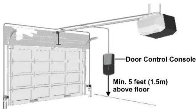
The Door Control Console is a wired, illuminated door control placed inside your garage.
Door Control Console Installation
● Inside your garage, install the control console within sight of the door at a minimum height of 5 feet (1.5 m) above the floor.
- Ensure that the console is installed out of reach of children and is free from contact with moving parts of the door.
- Install the console onto a solid mounting surface. If mounting to drywall, drill 3/16" holes and use provided drywall anchors.
- Hold the console against the mounting surface and mark the console bottom hole position on the surface.
- Remove the console from the surface. Drill a 5/32" pilot hole at the mark. Install the bottom screw into the surface. Allow 1/8" of the screw to protrude above the surface. Position bottom hole on back of console over the screw and slide console down into place.
- Lift the console actuation cover to expose the top screw hole. Mark the top screw hole position on the mounting surface. Remove the console from the surface and drill a 5/32" pilot hole at the mark.
- Position bottom hole on back of console over the bottom screw and slide console down into place. Install the top screw through the top screw hole and into the mounting surface.
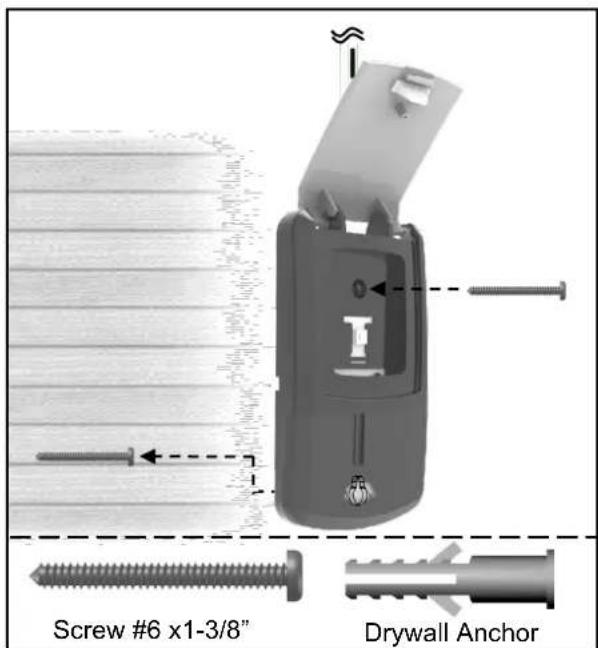
Fig. 1
To Connect the Door Control Console to the Opener
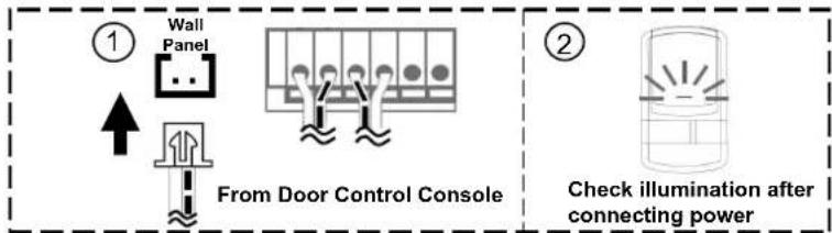
Connect the plug from the Door Control Console to the "Wall Panel" outlet on the rear of the Opener, as shown in Fig.2.
flowchart
graph TD
    A["① Wall Panel"] --> B["From Door Control Console"]
    B --> C["Check illumination after connecting power"]
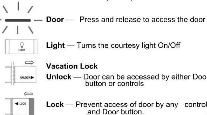
Using the Door Control Console
(ONLY after installation is completed)
Fig. 2
Connecting Power

WARNING
To prevent SERIOUS INJURY or DEATH from electrocution or fire:
- Power MUST be DISCONNECTED BEFORE proceeding with permanent wiring procedures.
- Garage door opener installation and wiring MUST be in compliance with all local electrical and building codes. Make sure the opener is ALWAYS grounded.
- NEVER use an extension cord, 2-wire adapter or modify the power plug in any way to make it fit the outlet.
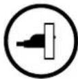
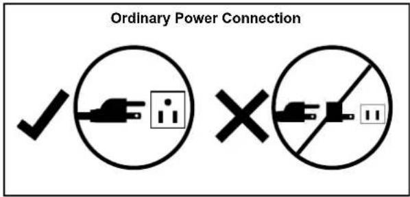
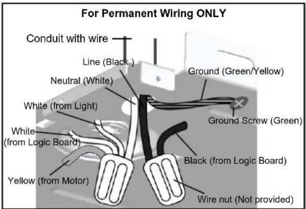
DO NOT OPERATE OPENER AT THIS TIME.
To Connect Power
Plug the opener into a grounded outlet ONLY. If there is no grounded outlet present, call a qualified electrician to replace the outlet. Use of a surge protector is highly recommended.
Permanent Wiring (If Required by Local Code)
- Remove the enclosure by removing the 6 screws located on the sides and rear of the opener.
- Cut the two cable pressure connectors connecting line (black) and neutral (white) wire from the power cord.
- Remove the grounding screw connecting the green wire.
- Remove the power cord.
- Group neutral (white) wires from power source with 2 white wires from light cable, and logic board, and yellow wire from motor, inside the opener. Connect them with a wire nut.
- Group line (black) wires from power source with another black wires from logic board inside the opener. Connect them with a wire nut.
- Secure the ground (green or bare) wire from the power source with a grounding screw.
- Reinstall the enclosure.
- Turn on power supply. If the wiring is properly connected, a "click" should be heard and the light will illuminate (if a bulb is installed). If there is no response from the opener, check power source and wiring.
Aligning the Photo Eye Safety System

WARNING
To prevent SERIOUS INJURY or DEATH from a closing garage door:
- The photo eye safety system MUST be installed BEFORE connecting power.
- The photo eye safety system MUST be properly connected and aligned BEFORE operating the opener.
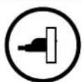
NOTICE: The opener will not close until the photo eyes are installed. Photo eyes are required by federal law to be installed on all openers.
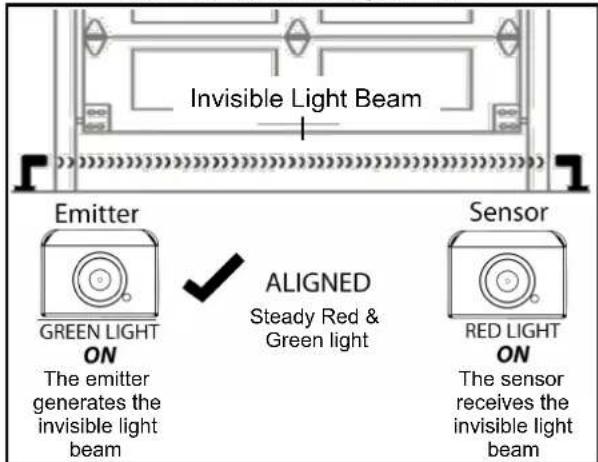
Aligning the Photo Eye Safety System:
- When power is supplied, the green photo eye (Emitter) will flash until it is aligned with the red photo eye (sensor). The red photo eye will not light until it is aligned with the green eye.
- When the photo eye system is properly aligned the green photo eye (emitter) will emit a steady green light and the red photo eye (sensor) will emit a steady red light.
- If either of the photo eye lights are unsteady, flash or dim, check for an obstruction and carefully adjust the position of the photo eyes until they give a steady green light and steady red light.
Note: The path of the invisible light beam MUST NOT be obstructed. No part of the garage door or any hardware should interfere or block either sensor.

WARNING
To prevent SERIOUS INJURY or DEATH from improper force adjustment:
- Improper adjustment of travel limits will cause operation of safety reversal mechanism.
- If travel limit adjustment is made, force adjustment may also needed.
- After ANY adjustments, the safety reverse test MUST be performed to ensure the door reverses on contact with a 1-1/2" thick object (2x4 laid flat).
If the door reverses unintentionally during closing, check below symptoms:
- The photo eye system may be improperly connected, misaligned or obstructed The courtesy light will flash continuously for 30 seconds. Refer to Troubleshooting on Page 25.
- Binding door — disconnect the door from the opener by using the emergency release handle. Open and close the door manually and check the following steps.
2.1 If the door is balanced, refer to Force Adjustment on Page 18 to adjust Close force.
2.2 If the door is unbalanced, binding or jammed, call a trained service person to adjust the door.
About Travel Limits
Limit adjustments regulate the position at which the door will stop when opening and closing.
BEFORE making any adjustments, operate the door by using the push button or remote. Run the opener through a complete cycle.
If the door opens and closes completely without unintended reversing upon closing — NO adjustment is necessary.
If the door does not open or close at desired positions, proceed with the instructions below to adjust the travel limits.
Adjusting Travel Limits
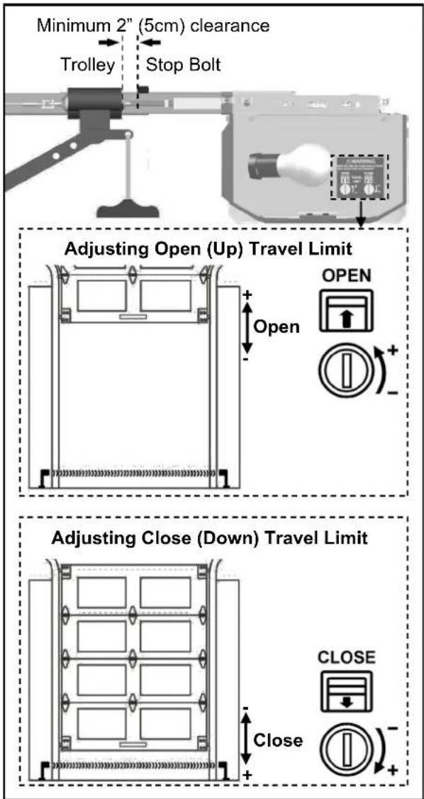
Open and close limits can be increased (+) or decreased (-) by turning the corresponding screws on the opener. Use a "flat head" screwdriver to make adjustments. One full turn of the screw is about 2" (5cm) of actual travel.
NOTE: The opener motor includes an automatic thermal protection system which will shut down the motor in an overheat situation. The thermal protector will reset itself once the motor cools down. Opening and closing the opener multiple times (in a short period of time) may cause the motor to overheat and shut down. If this happens, wait about 15 minutes for the motor to cool and retry operation.
Setting OPEN (UP) Travel Limit
- CLOSE the garage door by using either the remote or push button.
- Adjust the OPEN limit screw.
- OPEN garage door and check for proper adjustment.
- Repeat steps 1-3 until the door opens to the desired position. When the door is in the open position, make sure there is enough clearance for your vehicle(s), and there is a minimum 2" (5cm) gap between trolley and stop bolt.
- Perform Safety Reverse Test on page 19.
If the door does not open past 5 feet (1.5m), follow Force Adjustment on page 18 to adjust the open force.
Setting CLOSE (DOWN) Travel Limit
- OPEN the garage door by using either the remote or large push button.
- Adjust the CLOSE limit screw.
- CLOSE the garage door and check for proper adjustment.
- Repeat steps 1-3 until door closes to the desired position.
- Perform Safety Reverse Test on page 19.

WARNING
To prevent SERIOUS INJURY or DEATH from improper force adjustment:
- DO NOT adjust force to compensate for binding or sticking of the garage door. Call a qualified garage door service technician to make necessary adjustments in case of binding.
- DO NOT increase the force beyond minimum force required for closing the door. Too much force will cause improper operation of safety reversal mechanism.
- If either the force or travel limit adjustment is made, the other adjustment may also needed.
- After ANY adjustments, the safety reverse test MUST be performed to ensure the door reverses on contact with a 1-1/2" thick object (2x4 laid flat).
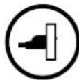
For safe operation, the force setting should always be set at the MINIMUM FORCE required to run the door.
Adjusting Force
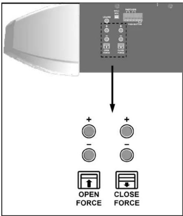
- Force adjustment controls are located on the rear panel of the opener. The force adjustments regulate the amount of force required to open or close the door.
- Force adjustment is applied only to compensate for the minor resistance caused by weather or other conditions.
- Note: Force is preset at level 6 for both open and close adjustments. The size and operating conditions of the garage door will determine the correct level of force/sensitivity. Weather conditions may also affect the operation of the door requiring further adjustments as needed.
- Note: If the close force is set too light the opener will reverse the door during closing. If the open force is set too light the opener will stop the door during opening.
- Note: There are 12 levels for open and close force settings. When either the maximum or minimum level is reached, the light will flash 6 times.
- Never adjust the force setting by more than 1 level (1 press) at a time.
Setting Force
Setting Close Force
- If the door completes a full close cycle without reversing, decrease (-) the close force by 1 level at a time until the door reverses. If the door reverses during closing, increase (+) close force by 1 level. The close force is now properly adjusted.
- During the "door-close" cycle, the opener will reverse if the force required to close the door is exceeded.
Setting Open Force
-
If the door completes a full open cycle without stopping, decrease (-) the amount of force by 1 level until the door stops during the opening. Once the door stops during opening, increase (+) open force by 1 level. The close force is now properly adjusted.
-
During the "door-open" cycle the opener will stop if the force required to open the door is exceeded.

WARNING
To prevent SERIOUS INJURY or DEATH from a closing garage door:
- The Safety Reversal Test MUST be conducted ONCE A MONTH.
- NO ONE should cross the path of moving door during operation and/or testing.
- If either force or travel limit adjustment is made, the other adjustment may also needed.
- After ANY adjustments to the door system, the Safety Reverse Test MUST be performed to ensure the door reverses on contact with a 1-1/2" thick (2x4 laid flat) object.
- The photo eye safety system MUST be properly aligned, and tested regularly.
natural_image
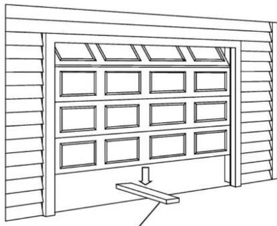
Line drawing of a modular storage unit with 12 windows and a central load (no text or symbols)1-1/2" (3.8cm) thick solid object (or 2x4 laid flat)
natural_image
Illustration of a capsule-shaped object with radiating lines and an hourglass, labeled '30 seconds' (no text or symbols on the object itself)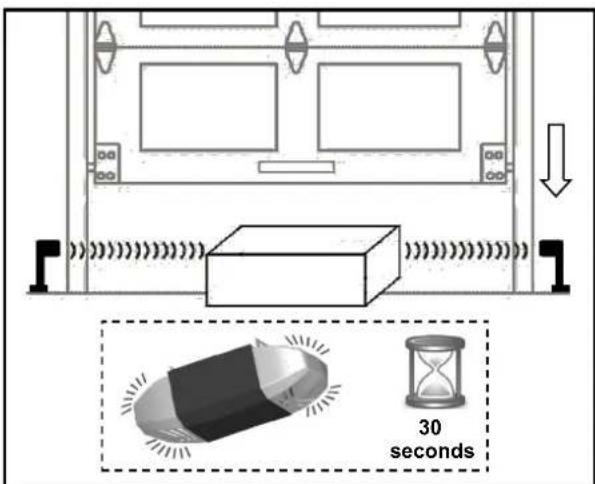
Testing the Safety Reverse System
The Safety Reverse System prevents the door from closing when an obstruction is present.
- Open the door by using the large push button or remote
- Place a 1-1/2" (3.8cm) thick solid object (or 2x4 laid flat) on floor under the center of garage door.
- Keeping the door in sight, use the large push button on the control console or remote to close the door.
- The door MUST REVERSE upon striking the object within 1.5 seconds, and stop at the fully opened position.
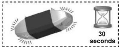
- The courtesy light will start flashing for 30 seconds upon triggering the Safety Reverse System.
If the door just stops on the object, adjust the opener as follows:
The close travel maybe inadequate, Increase close travel limit by 1/4 turn (See Limit Adjustment on page 17)
Conduct the test again. If the door reverses on contact, remove the object and run at least 3 COMPLETE travel cycles to ensure proper adjustment.
If the door still does not reverse on the object, decrease the close force (see Force Adjustment on page 18) and repeat the test.
If the opener still fails the safety reverse test, call a qualified technician for door adjustment.
Testing the Photo Eye Safety System
- Open the door by using the large push button or remote
- Make sure both photo eyes steadily emit the green and red indicator lights. (If not, check alignment)
- Place an object under the door about 8" (20cm) high by 12" (30cm) wide (the opener carton can be used),
- The red indicator light on the sensor eye should be dimmed.
- Keep the door in sight and use the large push button or remote to try to close the door.
- The door should NOT move more than 1" (2.5cm) and the courtesy light should flash for 30 seconds.
Programming 3-Button Remote

WARNING
To prevent SERIOUS INJURY or DEATH:
- Keep remote and battery out of reach of children.
- NEVER permit children to access the wall panel nor remotes.
- Operate the door ONLY when it is properly adjusted, and there are no obstructions present.
- ALWAYS keep a moving door in sight until completely closed. NEVER cross the path of a moving door.
To reduce risk of fire, explosion or electric shock:
- DO NOT short circuit, recharge, dissemble or heat the battery, batteries may explode or leak.
- NEVER allow small children near batteries.
- Replace with 27AE 12 volt batteries ONLY. Dispose of batteries properly.
natural_image
Illustration showing a hand pressing a device next to a 3D rendered object labeled 'x2' (no text or symbols on the object itself)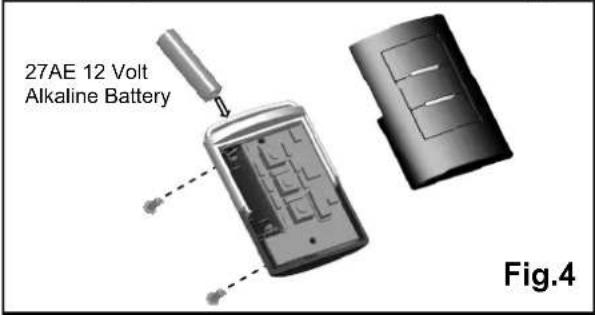
To Program Remote(s):
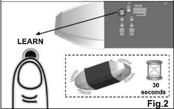
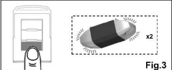
- See Fig.2 to add a remote. Press the "LEARN" button on the rear control panel of the opener. The courtesy light will illuminate with an audible click*. The unit is now ready to learn a remote.
- Within 30 seconds, press the button on the remote.
- The courtesy light will flash twice indicating remote has been stored successfully**.
Up to 20 remotes (including keyless entry pad codes) can be added to the unit by repeating the above procedures.
If more than 20 remotes are stored, the first stored remote will be replaced. (i.e. the 21st remote replaces the 1st stored remote.)
* If the courtesy light is already on, it will flash once and stay illuminated for 30 seconds.
** If a remote is not accepted, the courtesy light will stay on for 30 seconds, flash 4 times and then stay on for 2-1/2 minutes. Retry programming the remote by repeating the steps above.
Removing all Remotes:
To remove all remotes from memory, press and hold the "LEARN" button for 5 seconds. The courtesy light will flash 7 times indicating all remotes have been removed from memory.
Replacing Remote Battery:
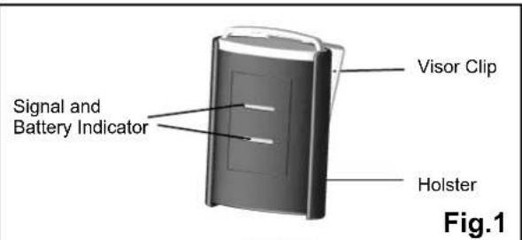
When the battery of the hand held remote is low, the indicator light will become dim and/or the range of the remote will diminish. To replace the battery, remove the battery cover from the remote as shown in Fig 4. Replace with a 27AE 12 volt alkaline battery with polarity shown in Fig.4.
Warning: Changes or modifications to this unit not expressly approved by the party responsible for compliance could void the user's authority to operate the equipment.
NOTE: This equipment has been tested and found to comply with the limits for a Class B digital device, pursuant to Part 15 of the FCC Rules. These limits are designed to provide reasonable protection against harmful interference in a residential installation. This equipment generates, uses and can radiate radio frequency energy and, if not installed and used in accordance with the instructions, may cause harmful interference to radio communications.
However, there is no guarantee that interference will not occur in a particular installation. If this equipment does cause harmful interference to radio or television reception, which can be determined by turning the equipment off and on, the user is encouraged to try to correct the interference by one or more of the following measures:
- Reorient or relocate the receiving antenna.
- Increase the separation between the equipment and receiver.
- Connect the equipment into an outlet on a circuit different from that to which the receiver is connected.
Consult the dealer or an experienced radio/TV technician for help.
Programming Wireless Keyless Entry Keypad
WARNING
To prevent SERIOUS INJURY or DEATH:
- Keep remote and battery out of reach of children.
- NEVER permit children to access the wall panel, push button nor remotes.
- Operate door only when it is adjusted properly with no obstructions to door travel and is in clear sight.
- ALWAYS keep a moving door in sight until completely closed. NO ONE should cross the path of a moving door.
To reduce risk of fire, explosion or electric shock: - DO NOT short circuit, recharge, dissemble or heat the battery, batteries may explode or leak.
- Replace with 1.5 volt AAA batteries ONLY. Dispose of batteries properly.
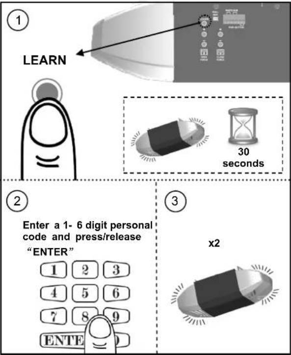
Fig.1
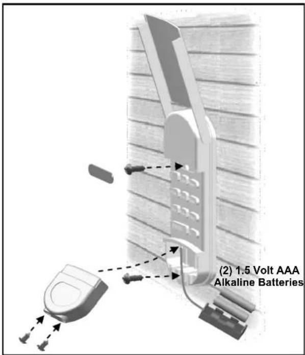
Fig.2
To Add Personal Codes:
- Press the "LEARN" button on the rear control panel, "OK" LED will glow and beep. The unit is ready to accept a keypad code in the next 30 seconds as shown in Fig.1.
- Enter a 1 - 6 digit personal code on the keyless entry within 30 seconds and press/release "ENTER" button. "OK" LED will flash and beep twice indicating personal code is stored in memory.
Up to 20 personal codes (including 1-button remotes) can be added to the unit by repeating the above procedures.
If more than 20 personal codes are stored, the previously stored one from the very beginning will be replaced, (i.e. the 21st code replaces the 1st stored one.)
Operation:
To access the door, enter a pre-stored personal code and press "ENTER" to transmit code, and within 20 seconds, "ENTER" button can be used to stop or reverse the door.
If the code is entered incorrectly, correction can be made by pressing "ENTER" to reset and re-enter code.
When dark, "ENTER" may be pressed in advance to turn on back light.
Removing ALL Personal Code(s):
To remove ALL personal code(s) from memory, press and hold the "LEARN" button for 5 seconds. "OK" LED will flash and beep, indicating all codes/remotes have been removed from memory.
Mounting the Keyless Entry:
Keyless entry may be secured on door jamb face outside your garage. Locate keyless entry within sight of door at minimum height of 5 feet (1.5m), ensure it is away from reach of children and moving parts of door and hardware. Test the reception of the keyless entry before mounting. Change location for better reception if necessary.
Use the mounting holes on the keyless entry as template to mark position on the mounting surface. To attach to a wooden surface use the screws provided. In case of a drywall surface, drill holes and use drywall anchors provided.
Replacing Keyless Entry Battery:
When the battery of keyless entry is low, dimmed illumination is observed. To replace battery, remove the battery cover by loosening the screws underneath, and replace the battery with two 1.5 volt AAA batteries.
IMPORTANT SAFETY INSTRUCTIONS
⚠ WARNING
To reduce the risk of severe injury or death:
- READ AND FOLLOW ALL INSTRUCTIONS.
- Never let children operate or play with door controls. Keep the remote control away from children.
- Always keep the moving door in sight and away from people and objects until it is completely closed. NO ONE SHOULD CROSS THE PATH OF THE MOVING DOOR.
- NEVER GO UNDER A STOPPED, PARTIALLY OPEN DOOR.
- Test door opener monthly. The garage door MUST reverse on contact with a 1-1/2-inch high object (or a 2 by 4 board laid flat) on the floor. After adjusting either the force or the limit of travel, retest the door opener. Failure to adjust the opener properly increases the risk of severe injury or death.
- Use the emergency release only when the door is closed. Use caution when using this release with the door open. Weak or broken springs are capable of increasing the rate of door closure and increasing the risk of severe injury or death.
- KEEP GARAGE DOORS PROPERLY BALANCED. See owner's manual. An improperly balanced door increases the risk of severe injury or death. Have a qualified service person make repairs to cables, spring assemblies, and other hardware.
SAVE THESE INSTRUCTIONS.
Operating the Opener

WARNING
To prevent SERIOUS INJURY or DEATH:
- READ AND FOLLOW ALL INSTRUCTIONS AND WARNINGS IN THE OWNER'S MANUAL AND LABELS
- Keep remote and battery out of reach of children.
- NEVER permit children to access the door control console or remotes.
- Operate the door ONLY when it is properly adjusted, and there are no obstructions and is in clear sight.
- ALWAYS keep a moving door in sight until completely closed. NEVER cross the path of a moving door.
- If travel limit adjustment is made, force adjustment may also needed.
- After ANY adjustments, the safety reverse test MUST be performed to ensure the door reverses on contact with a 1-1/2" thick object (2x4 laid flat).
- ALWAYS ensure that your door is balanced and in good working condition.
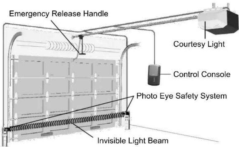
Actual Operating Scenario
Activating the Opener
| Controls Operation | ||
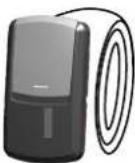 | Door Control Console (Indoor) | Press and hold the push button until the door starts to move, and controls as follows:- Open or close the door.- Reverse the door while it is closing- Stops the door while it is opening.- Close the door when the photo eye safety system is not installed, misaligned or obstructed INTENTIONALLY. |
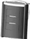 | 3-Button Mini Remote Control | Remote distance up to 100 ft. in open field.For safety concerns, the hand-held remote WILL NOT work if the photo eye safety system is not properly installed and aligned. |
 | Wireless Keyless Entry Keypad | Program the keyless entry pad accordingly and access the door using the PIN code. |
Door Status vs. Activation
| Door status |  | Activation using Door Control Console / Remote |
| Door at fully open / close position | Door will move to fully close / open position | |
| Door is closing | Door will reverse | |
| Door is opening | Door will stop | |
| Door is stopped as intended in partially open position | Close | |
| Door is obstructed while closing | Door will reverse while flashing courtesy light | |
| Door is obstructed while opening | Door will stop | |
| Door is fully opened and photo eye system is obstructed | Door will not close | |
Courtesy Light Responses
| Operation / Condition |  | Courtesy Light Response |
| Opener is initially plugged-in / Power restored | Flashes five times | |
| Upon opener activation | Turns on for 4-1/2 minutes and turns off automatically | |
| “LEARN” button is pressed Turns on for 30 seconds | ||
| Remote / Keyless entry PIN code accepted Flashes twice | ||
| The photo eye system is obstructed during door-closing or door is obstructed during opening | Flashes for 30 seconds (Re-align and clear obstruction) | |
| Opener motor overheat (Thermal Protection) | Flashes 5 times (Wait about 15 minutes to cool down) | |
Manual Operation
 | WARNING | |
| To prevent SERIOUS INJURY or DEATH:- Use emergency release to disconnect trolley ONLY when the door is CLOSED to prevent unexpected rapid falling in case of a unbalanced / poor-conditioned door.- Use emergency release ONLY when doorway is clear of persons and obstructions.- DO NOT use emergency release to pull the door open or closed. | ||
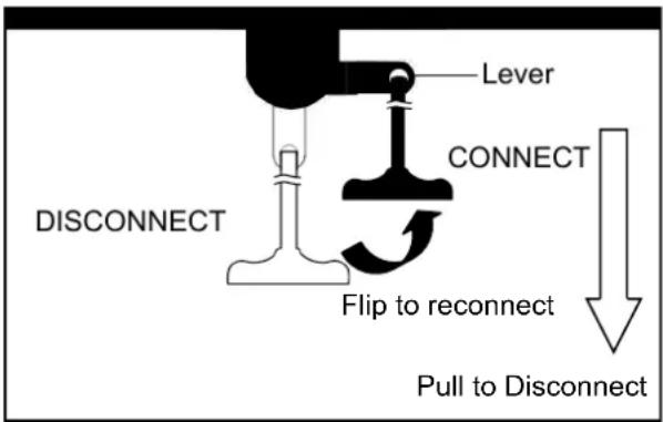
In case of a power failure or door obstruction, PULL EMERGENCY handle to release door from opener.
To Disconnect Trolley for Manual Operation
With the door closed, pull down the emergency release handle to the DISCONNECT position. The door can be raised / lowered manually.
To Re-connect Trolley
Pull the handle toward the opener so that the lever will flip up to the CONNECT position. The trolley will reconnect itself when the opener is activated or when the door is manually opened/closed
Maintenance
| Schedule Maintenance | |
| Once a month | Door balance test, refer to page 4.Safety reverse test, refer to page 19. |
| Twice a year | Check chain tension (refer to page 6 for adjustment if necessary). |
| Once a year | - Limit and force adjustment may be necessary due to weather conditions.Refer to pages 17-18 for adjustment. Conduct safety reverse test after ANY adjustments.- Lubricate door rollers, bearings and hinges. The opener is permanently lubricated, DO NOT lubricate or grease the opener, rail or door tracks. |
Troubleshooting
| Problem Possible Cause / Solution | |
| Opener does not close and light flashes | The photo eye safety system is misaligned or obstructed, refer to pages 16 for proper alignment. |
| Opener does not respond to remote | - Refer page 20 to reprogram remote.- Check remote battery |
| Opener stops before reaching full open / close position | Either the travel limit or force is not properly adjusted, check adjustment referring to pages 17-18. Conduct safety reverse test after ANY adjustment. |
| The door reverses unintentionally | - Make sure the photo eye safety system is aligned and clear of obstructions.- Refer to page 4 to check the door balance- Refer to page 18 to re-adjust the force |
| The door reverses upon touching the floor and the courtesy light flashes | Refer to page 17 to decrease close limit by 1/4 turn until door stops as intended at the fully closed position. Conduct safety reverse test after ANY adjustment. |
| The courtesy light flashes 5 times and the Opener does not start | Opener motor overheat, please wait about 15 minutes and retry. |
| The opener does not close the door and the green LED on the photo eyes flashes | The photo eye safety system is misaligned or obstructed, refer to page16 for proper alignment. |
| The opener is working properly but the courtesy light does not turn on | Replace light bulb (A19 incandescent Max.100W). |
| The courtesy light does not turn off Defective logic board. | |
| The opener hums as the trolley hits the trolley stop bolt in open travel | 1. Make sure the trolley is towards the trolley stop bolt.2. Disconnect the trolley by using the emergency release.3. Close the door manually4. Relieve the chain tension by loosening both the chain-to-cable connector and the flange nut (see page 6)5. Operate the opener so the trolley shaft travels towards the door (Trolley should be kept disconnected)6. Refer to page 17 to decrease open travel limit by 2 full turns7. Refer to page 6 to re-tighten the chain until it is 1/4" (6mm) above the base of rail (reference the figure shown on page 6).8. Repeat the above steps if the trolley still hits the stop bolt. |
To purchase repair parts, call 1-888-331-4569.
Rail Assembly Parts
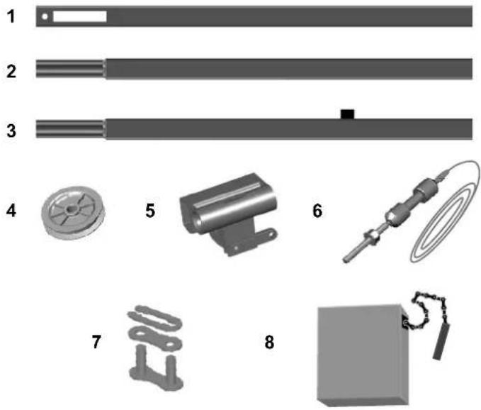
| Item | Part No. | Name / Description |
| 1 | RP-001 | Rail—Header Segment |
| 2 | RP-002 | Rail—Middle Segments |
| 3 | RP-003 | Rail—End Segment with Stop Bolt |
| 4 | GUT-840 | Pulley |
| 5 | RP-004 | Trolley |
| 6 | RP-005 | Trolley Shaft and Cable |
| 7 | GUT-410 | Master Link Set |
| 8 RP-006 Chain | ||
Installation Parts
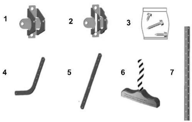
| Item | Part No. | Name / Description |
| 1 | RP-007 | Header Bracket |
| 2 | GUAT-022 | Door Bracket |
| 3 RP-008 | Hardware Bag with Emergency Release Handle& Rope (Installation hardware shown on P.3) | |
| 4 | GUAT-024 | Curved Door Arm |
| 5 | GUAT-025 | Straight Door Arm |
| 6 | GUAT-026 | Emergency Release Handle + Rope |
| 7 | RP-009 | Hanging Bracket |
Accessories
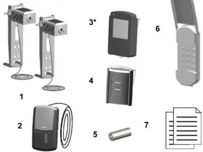
| Item | Part No. | Name / Description |
| 1 | GUAT-201 | Photo Eye Safety System (Emitter + Sensor with Brackets) |
| 2 | CR-007 | Door Control Console |
| 3 | 58502 | 1-Button Remote |
| 4 | 57938 | 3-Button Mini Remote |
| 5 | GUAT-210 | 27AE 12 Volt Alkaline Battery |
| 6 | 57939 | Keyless Entry Pad |
| 7 | CR-008 | Owner's Manual |
*Optional
To purchase optional accessories, visit a Craftsman outlet, call 1-888-331-4569, or go online to www.sears.com
Opener Assembly Parts
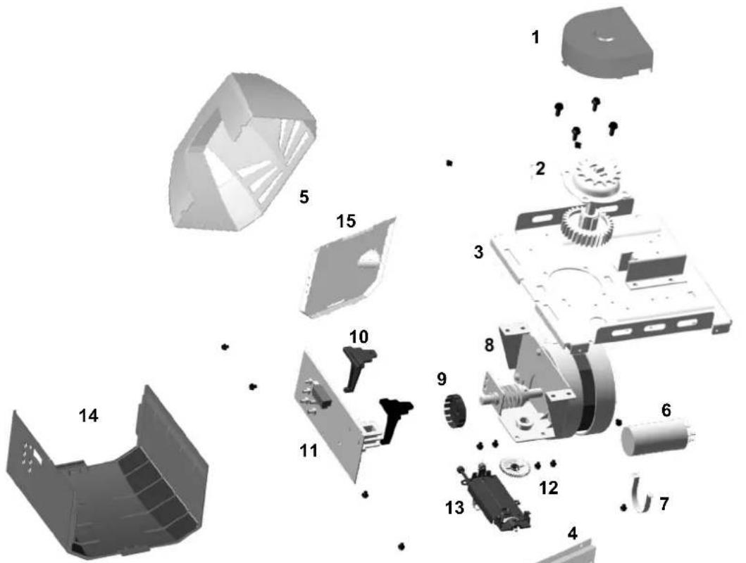
| Item | Part No. | Name / Description |
| 1 | GUAT-327 | Sprocket Cover |
| 2 | GUAT-323 | Sprocket and gear assembly |
| 3 | GUAT-341 | Chassis |
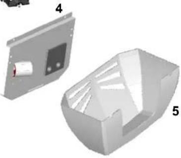
| 4 | GUAT-319 | Lamp Plate w/Limit Adj |
| 5 | CR-003 | Light Lens Cover |
| 6 | GUAT-305 | Capacitor |
| 7 | GUAT-306 | Capacitor holder |
| 8 CR-004 | AC Service Motor & Bracket Assembly | |
| 9 GUAT-308 | Garage Door Opener RPM Wheel | |
| 10 | GUAT-309 | Logic Board holder |
| 11 | GUAT-310 | Logic Board |
| 12 | GUAT-311 | Limit system driving gear |
| 13 | GUAT-312 | Limit system assembly |
| 14 | CR-035 | Opener cover |
| 15 | GUAT-303 | Lamp Plate |
natural_image
3D CAD model of a mechanical housing component with two views labeled 4 and 5 (no text or symbols on the housing itself)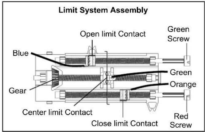
* Should be replaced by qualified technician only
CRAFTSMAN WARRANTY
90-DAY IN-HOME LIMITED WARRANTY
FOR 90 DAYS from the date of sale this product is warranted against defects in material or workmanship. With proof of purchase a defective product will be repaired free of charge.
LIMITED WARRANTY ON PARTS
FROM THE 91st DAY THROUGH 1 YEAR from the date of sale this product is warranted against defective parts. With proof of purchase a new part will be furnished to replace a defective one free of charge. Any costs for professional installation are not included.
LIMITED WARRANTY ON MOTOR
FROM THE 91st DAY THROUGH 10 YEARS from the date of sale the motor on this product is warranted against defects in material or workmanship. With proof of purchase a new motor will be furnished to replace a defective one free of charge. Any costs for professional installation are not included.
WARRANTY SERVICE
For warranty coverage details to obtain product repair or replacement parts, call this number: 1-888-331-4569
WARRANTY RESTRICTION
This warranty does not cover light bulbs, which are expendable parts, or repair parts necessary because of operator abuse or negligence, including the failure to install, adjust and operate this garage door opener according to instructions contained in the owner's manual. This warranty also does not cover any problems caused by interference.
LIMITATION ON LIABILITY
Seller will not be liable for loss or damage to property or any incidental or consequential loss or expense from property damage due directly or indirectly to the use of this product. Some states do not allow the exclusion or limitation of incidental or consequential damages, so the above limitation or exclusion may not apply to you.
DISCLAIMER OF IMPLIED WARRANTIES
Except for the motor, all implied warranties for this product, including but not limited to any implied warranties of merchantability and fitness for a particular purpose, are limited in duration to the 90 day and 91st day through 1-year limited warranty period set forth above. All implied warranties with respect to the motor are limited in duration to the 91st day through 10-year limited warranty period set forth above. No implied warranties will exist or apply after such periods. Some states do not allow limitations on how long an implied warranty lasts, so the above limitations may not apply to you.
This warranty applies only while this product is in use in the United States.
This warranty gives you specific legal rights, and you may also have other rights which vary from state to state.
Transform SR Brands Management LLC, Hoffman Estates, IL 60179
Introducción
Símbolos e íconos 29
Inventario 30
natural_image
3D rendered object resembling a capsule or pill with a black band (no text or symbols)natural_image
Pure mechanical components without any text or symbolsSoportes Colgantes
Soporte de cabecera

Polea
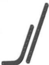
Brazos de la Puerta
natural_image
Diagram showing mechanical assembly steps: (a) fixed supports, (b) clamped joints, and (c) assembled frame with a handle (no text or symbols)Fig.3

ADVERTENCIA
natural_image
Close-up of a metallic screw with threaded shaft and hexagonal end (no text or symbols)Tornillos de Tirafondo 5/16" x 1-1/2"
natural_image
Diagram of a mechanical linkage system with a circular component and connecting rod (no text or symbols)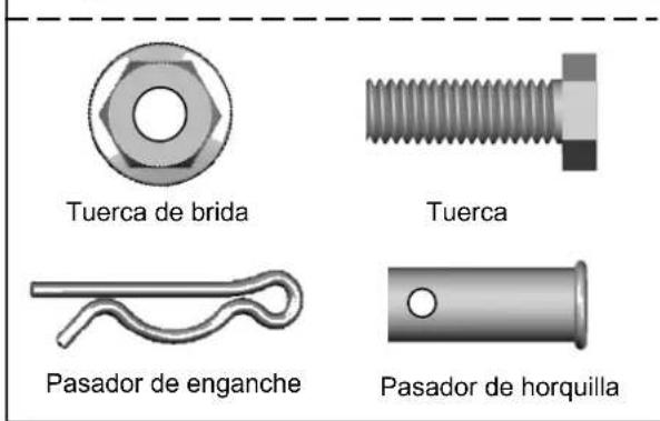
Fig.1
Para instalar la luz:
natural_image
Diagram showing a device with a finger pressing it and a 3D object labeled 'x2' inside a dashed box, marked as Fig.3 (no text or symbols on the diagram itself)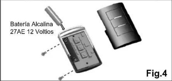
natural_image
Collection of mechanical parts and components, including a ruler, shafts, housing, and accessories (no text or symbols visible)To order replacement parts or schedule repair service
- Assembly
- Installation
- Wiring
- Adjustment
- Operation
- Repair Parts and Service
- Symbols and Icons
- WARNING
- Inventory
- INSTALLATION HARDWARE, LOCATED IN HARDWARE BAG (SHOWN IN ACTUAL SIZE)
- DO NOT REUSE PARTS FROM ANOTHER BRAND OF OPENER!!!
- BEFORE beginning Installation:
- To Test Your Garage Door
- Tools Required
- To Assemble Rail and Opener
- To Assemble the Header Section of Rail
- To Link Cable with Chain
- To prevent SERIOUS INJURY:
- To Install Chain
- Notice
- Important Installation Instructions
- To reduce the risk of severe injury or death:
- To Install Header Bracket
- Wall-Mounting
- Alternative Ceiling-Mounting
- Attaching Rail to Header Bracket and Mounting Door Bracket
- CAUTION
- To Attach the Opener to the Header Bracket
- To mount the Door Bracket
- Wood door
- To Mount the Opener to Ceiling
- To Connect Door Arm
- Installing Light and Emergency Release Handle
- To install the light:
- To attach the Emergency Release Handle:
- \* VERY IMPORTANT! \*
- Wiring Instructions
- Connecting Photo Eye Safety System
- About the Photo Eye Safety System
- Installing The Photo Eye Safety System
- Alternative Floor-mounting
- To Connect Photo Eye Safety System
- Door Control Console Installation
- To Connect the Door Control Console to the Opener
- Connecting Power
- DO NOT OPERATE OPENER AT THIS TIME.
- To Connect Power
- Permanent Wiring (If Required by Local Code)
- Aligning the Photo Eye Safety System
- Aligning the Photo Eye Safety System:
- If the door reverses unintentionally during closing, check below symptoms:
- About Travel Limits
- Adjusting Travel Limits
- Setting OPEN (UP) Travel Limit
- Setting CLOSE (DOWN) Travel Limit
- Adjusting Force
- Setting Force
- Setting Close Force
- Setting Open Force
- Testing the Safety Reverse System
- The Safety Reverse System prevents the door from closing when an obstruction is present.
- Testing the Photo Eye Safety System
- Programming 3-Button Remote
- To Program Remote(s):
- Removing all Remotes:
- Replacing Remote Battery:
- Programming Wireless Keyless Entry Keypad
- To prevent SERIOUS INJURY or DEATH:
- To Add Personal Codes:
- Operation:
- Removing ALL Personal Code(s):
- Mounting the Keyless Entry:
- Replacing Keyless Entry Battery:
- IMPORTANT SAFETY INSTRUCTIONS
- ⚠ WARNING
- SAVE THESE INSTRUCTIONS.
- Operating the Opener
- Door Status vs. Activation
- To Disconnect Trolley for Manual Operation
- To Re-connect Trolley
- Maintenance
- Opener Assembly Parts
- CRAFTSMAN WARRANTY
- 90-DAY IN-HOME LIMITED WARRANTY
- LIMITED WARRANTY ON PARTS
- LIMITED WARRANTY ON MOTOR
- WARRANTY SERVICE
- WARRANTY RESTRICTION
- LIMITATION ON LIABILITY
- DISCLAIMER OF IMPLIED WARRANTIES
- Introducción
- ADVERTENCIA
- Para instalar la luz:
Brand : Craftsman
Model : 57953
Category : Garage door opener