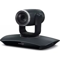
VC110 - Video Conferencing System Yealink - Free user manual and instructions
Find the device manual for free VC110 Yealink in PDF.


| Product Type | All-in-one HD Video Conferencing Endpoint |
| Model | VC110 |
| Brand | Yealink |
| Video Resolution | 1080p full HD |
| Camera Digital Zoom | 4x |
| Camera Pan Range | ±100° |
| Camera Tilt Range | ±30° |
| Built-in Microphone | Yes |
| External Audio Support | VCM60 wireless microphone, VCM30 microphone array, VCP40/41 video conferencing phone |
| Video Outputs | 2x HDMI (Display1 and Display2) |
| Network Connectivity | 10/100/1000 Mbps Ethernet (RJ45) |
| Power Supply | DC 12V/2A or PoE (IEEE 802.3af) |
| Remote Control | VCR10 with IR sensor |
| Mounting Options | Table or wall mount using included L-bracket |
| Included Accessories | VC110 unit, cable hub, remote control, AAA batteries, power adapter, DVI cable, HDMI cable, Ethernet cable (2m), HDMI-VGA cable, cable ties, L-bracket, mounting screws, expansion bolts, velcro, quick start guide |
| Web Interface | Yes (for configuration and management) |
| Supported Cloud Platforms | Yealink Cloud, YMS, StarLeaf, Zoom, BlueJeans, Pexip, Mind, Custom |
| Security Features | Administrator password, meeting blacklist, USB disable |
| Languages | English, Chinese, French, German, Italian, Polish, Portuguese, Spanish, Turkish, Russian, Czech |
| Compliance | RoHS |
| Maintenance | Clean with a soft, dry, anti-static cloth. Do not use liquid or aerosol cleaners. |
| Safety | Keep device dry, avoid direct sunlight, use only Yealink original power adapter. Do not disassemble. |
| Spare Parts | Contact Yealink authorized reseller for spare parts availability. |
Frequently Asked Questions - VC110 Yealink
User questions about VC110 Yealink
0 question about this device. Answer the ones you know or ask your own.
Ask a new question about this device
Download the instructions for your Video Conferencing System in PDF format for free! Find your manual VC110 - Yealink and take your electronic device back in hand. On this page are published all the documents necessary for the use of your device. VC110 by Yealink.
USER MANUAL VC110 Yealink
VC110 Video Conferencing Endpoint User Guide
Version 30.20
Aug.2017
Copyright
Copyright © 2017 YEALINK (XIAMEN) NETWORK TECHNOLOGY
Copyright © 2017 Yealink (Xiamen) Network Technology CO., LTD. All rights reserved. No parts of this publication may be reproduced or transmitted in any form or by any means, electronic or mechanical, photocopying, recording, or otherwise, for any purpose, without the express written permission of Yealink (Xiamen) Network Technology CO., LTD. Under the law, reproducing includes translating into another language or format.
When this publication is made available on media, Yealink (Xiamen) Network Technology CO., LTD. gives its consent to downloading and printing copies of the content provided in this file only for private use but not for redistribution. No parts of this publication may be subject to alteration, modification or commercial use. Yealink (Xiamen) Network Technology CO., LTD. will not be liable for any damages arising from use of an illegally modified or altered publication.
Trademarks
Yealink®, the logo and the name and marks is trademark of Yealink (Xiamen) Network Technology CO., LTD, which are registered legally in China, the United States, EU (European Union) and other countries.
All other trademarks belong to their respective owners. Without Yealink's express written permission, recipient shall not reproduce or transmit any portion hereof in any form or by any means, with any purpose other than personal use.
Warranty
(1) Warranty
THE SPECIFICATIONS AND INFORMATION REGARDING THE PRODUCTS IN THIS GUIDE ARE SUBJECT TO CHANGE WITHOUT NOTICE. ALL STATEMENTS, INFORMATION, AND RECOMMENDATIONS IN THIS GUIDE ARE BELIEVED TO BE ACCURATE AND PRESENTED WITHOUT WARRANTY OF ANY KIND, EXPRESS OR IMPLIED. USERS MUST TAKE FULL RESPONSIBILITY FOR THEIR APPLICATION OF PRODUCTS.
(2) Disclaimer
YEALINK (XIAMEN) NETWORK TECHNOLOGY CO., LTD. MAKES NO WARRANTY OF ANY KIND WITH REGARD TO THIS GUIDE, INCLUDING, BUT NOT LIMITED TO, THE IMPLIED WARRANTIES OF MERCHANTABILITY AND FITNESS FOR A PARTICULAR PURPOSE. Yealink (Xiamen) Network Technology CO., LTD. shall not be liable for errors contained herein nor for incidental or consequential damages in connection with the furnishing, performance, or use of this guide.
(3) Limitation of Liability
Yealink and/or its respective suppliers are not responsible for the suitability of the information contained in this document for any reason. The information is provided "as is", and Yealink does not provide any warranty and is subject to change without notice. All risks other than risks caused by use of the information are borne by the recipient. In no event, even if Yealink has been suggested the occurrence of damages that are direct, consequential, incidental, special, punitive or whatsoever (Including but not limited to loss of business profit, business interruption or loss of business information), shall not be liable for these damages.
End User License Agreement
This End User License Agreement ("EULA") is a legal agreement between you and Yealink. By installing, copying or otherwise using the Products, you: (1) agree to be bounded by the terms of this EULA, (2) you are the owner or an authorized user of the device, and (3) you represent and warrant that you have the right, authority and capacity to enter into this agreement and to abide by all its terms and conditions, just as if you had signed it. The EULA for this product is available on the Yealink Support page for the product.
Patent Information
China, the United States, EU (European Union) and other countries are protecting one or more patents of accompanying products and/or patents being applied by Yealink.
Customer Feedback
We are striving to improve our documentation quality and we appreciate your feedback. Email your opinions and comments to DocsFeedback@yealink.com.
Technical Support
Visit Yealink WIKI (http://support.yealink.com) for the latest firmware, guides, FAQ, Product documents, and more. For better service, we sincerely recommend you to use Yealink Ticketing system (https://ticket.yealink.com) to submit all your technical issues.
GNU GPL INFORMATION
Yealink VC110 video conferencing endpoint firmware contains third-party software under the GNU General Public License (GPL). Yealink uses software under the specific terms of the GPL. Please refer to the GPL for the exact terms and conditions of the license.
The original GPL license, source code of components licensed under GPL and used in Yealink products can be downloaded online:
http://www.yealink.com/GPLOpenSource.aspx?BaseInfoCateId=293&NewsCateId=293&CateId=293.
About This Guide
Thank you for choosing the Yealink VC110 full HD video conferencing endpoint. It is an all-in-one unit that supports 1080P-full HD video conferencing and includes outstanding features such as good compatibility, easy deployment and intelligent network adaptability.
These make it the best choice for SME.
The Yealink VC110 full-HD video conferencing endpoint is designed to help enterprises organize video conferences easily and efficiently. Users can expect to enjoy the high-quality video conferencing experience very cost-effectively.
This guide provides everything you need to start using your new video conferencing endpoint quickly. First, verify with your system administrator that the IP network is ready for endpoint configuration. Also be sure to read the Overview and Getting Started sections in this guide before you set up and use the VC110 video conferencing endpoint.
See the Yealink Products Regulatory Notices Guide for all regulatory and safety guidance.
Chapters in This Guide
Topics provided in this guide include:
• Chapter 1 Overview
• Chapter 2 Getting Started
• Chapter 3 Customizing the VC110 Video Conferencing Endpoint
• Chapter 4 Using the VC110 Video Conferencing Endpoint
• Chapter 5 Using Cloud Platform
• Chapter 6 Using the VCM60 Video Conferencing Wireless Microphone
• Chapter 7 Using the VCM30 Video Conferencing Microphone Array
• Chapter 8 Using VCP41 with the PC or Mobile Device
• Chapter 9 Troubleshooting
Documentations
The following table shows documentations available for the VC110 video conferencing endpoint.
| Name | Contents | Where found | Language |
| Yealink VC110All-in-one HD Video ConferencingEndpoint Quick Start Guide | Endpoint installation and network configuration | On the website/In the package | English/Chinese |
| Yealink VC110All-in-one HD Video ConferencingEndpoint User Guide | Endpoint/Web user interface settingsCustomizing and using the endpoint | On the website | English/Chinese |
| Yealink VC110 Video Conference RoomDeployment Solution | Conference room layout, environmental requirements and installation recommendations for the endpoint | On the website | English/Chinese |
| Yealink VC SeriesVideo Conferencing System NetworkDeployment Solution | Network deployment for the VCS under various scenarios | On the website | English/Chinese |
| Yealink VC110All-in-one HD Video ConferencingEndpoint administrator Guide | Functionality and configuration of the Yealink VCS | On the website | English/Chinese |
Note
You can also download the latest documents online:
http://support.yealink.com/documentFront/forwardToDocumentFrontDisplayPage.
Typographic Conventions
Yealink documentations contain a few typographic conventions.
You need to know the following basic typographic conventions to distinguish types of in-text information:
| Convention | Description |
| Bold | Highlights the web/phone user interface items such as menus, menu selections, soft keys, or directory names when they are involved in a procedure or user action (e.g., Click on Setting ->General). Also used to emphasize text |
| Blue Text | Used for cross references to other sections within this documentation (e.g., refer to Troubleshooting). |
| Blue Text in Italics | Used for hyperlinks to Yealink resources outside of this documentation such as the Yealink documentations (e.g., For more information, refer to Yealink VC110 All-in-one HD Video Conferencing Endpoint Administrator Guide). |
You also need to know the following writing conventions to distinguish conditional information:
| Convention | Description |
| -> | Indicates that you need to select an item from a menu. For example, Settings->Basic Settings indicates that you need to select Basic Settings from the Settings menu. |
Terms
As you read this guide, you'll notice that the same terms are used repeatedly. Make sure you familiarize yourself with these terms.
Cloud platform: This term refers to Yealink VC Cloud Management Service, Yealink Meeting Server, Zoom, BlueJeans, Pexip, Mind and Custom platform.
Cloud account: This term refers to Yealink Cloud, YMS, BlueJeans, Pexip, Mind and Custom account.
Cloud contact: This term refers to Yealink Cloud contact and YMS contact.
Summary of Changes
This section describes the changes to this guide for each release and guide version.
Changes for Release 23, Guide Version 23.20
The following section is new for this version:
• Using the Yealink Meeting Server on page 117
Changes for Release 23, Guide Version 23.6
The following section is new for this version:
• Using the Yealink Meeting Server on page 117
Major updates have occurred to the following section:
- Placing a Call via Web User Interface on page 93
- Configuring Camera Presets on page 103
Changes for Release 22, Guide Version 22.15
The following section is new for this version:
• Account Polling on page 88
• Using the StarLeaf Cloud Platform on page 128
Major update has occurred to the following section:
• Changing the Video Input Source on page 101
Changes for Release 22, Guide Version 22.5
The following sections are new for this version:
• Virtual Remote Control on page 48
• Meeting Blacklist on page 57
• USB Configuration on page 62
• Using Cloud Platform on page 116
Major updates have occurred to the following sections:
• Icon Instructions on page 19
• Setup Wizard on page 35
• Registration on page 40
• Idle Screen Display on page 40
• Call History Management on page 73
- Configuring Camera Presets on page 103
• Video Recording on page 105
• Screenshot on page 110
Changes for Release 21, Guide Version 21.20
The following sections are new for this version:
- Keyboard Input Method on page 43 Major updates have occurred to the following sections:
• Icon Instructions on page 19
• Setup Wizard on page 35
• Directory on page 63
• Bandwidth Settings on page 80
- Placing a Call Using the Remote Control on page 92
Changes for Release 21, Guide Version 21.15
The following sections are new for this version:
• VCP41 Video Conferencing Phone on page 15
• Website Snapshot on page 57
• Hiding Icons in a Call on page 61
• Auto Recording on page 109
• Using VCP41 with the PC or Mobile Device on page 152
Major updates have occurred to the following sections:
• Packaging Contents on page 1
• Endpoint Component Instructions on page 7
• Icon Instructions on page 19
- Setup Wizard on page 35
Table of Contents
About This Guide ...... v
Chapters in This Guide....v
Documentations ......vi
Typographic Conventions......vii
Terms ......vii
Summary of Changes......viii
Changes for Release 23, Guide Version 23.15......viii
Changes for Release 23, Guide Version 23.6......viii
Changes for Release 22, Guide Version 22.15......viii
Changes for Release 22, Guide Version 22.5......viii
Changes for Release 21, Guide Version 21.20 ix
Changes for Release 21, Guide Version 21.15 ix
Table of Contents....xi
Overview....1
Packaging Contents....1
VC110 All-in-one Package .... 1
VCM60 Package....3
VCP40 Package 4
VCP41 Package 4
VCM30 Package....6
Endpoint Component Instructions....7
VC110 All-in-One Unit 7
Cable Hub 11
VCM60 Video Conferencing Wireless Microphone....12
Video Conferencing Phone....13
CPE80 Expansion Microphone....15
VCM30 Video Conferencing Microphone Array 16
VCR10 Remote Control 17
Icon Instructions....19
Icons on Display Device 19
Icons on Video Conferencing Phone 21
LED Instructions....23
User Interfaces....24
Web User Interface....24
Remote Control 25
Getting Started....28
Endpoint Connection and Installation 28
Connecting the VC110 Video Conferencing Endpoint 29
Installing the VC110 Video Conferencing Endpoint 30
Installing Batteries for the Remote Control....32
Powering the Endpoint On or Off 33
Setup Wizard 35
Controlling Local Camera 39
Registration 40
Idle Screen Display 40
Navigating Menus on the Display Device 42
Keyboard Input Method....43
Entering Data and Editing Fields....44
Endpoint Status....45
Customizing the VC110 Video Conferencing Endpoint......48
General Settings 48
Virtual Remote Control....48
Automatic Sleep Time....49
Backlight 50
Site Name....51
Language....52
Date & Time....54
Key Tone....56
Meeting Blacklist....57
Website Snapshot....58
Volume Settings 59
Hiding Icons in a Call....61
USB Configuration....62
Directory....63
Adding Local Contacts....64
Placing Calls to Contacts....65
Editing Local Contacts....66
Deleting Local Contacts 67
Searching for Contacts 68
Search Source List in Dialing 69
Importing/Exporting Local Contact Lists 71
Call History Management....73
Viewing Call History....74
Placing a Call from the Call History List....75
Deleting an Entry from the Call History List....76
Adding a Local Contact from the Call History List....78
Call Protocol....79
Bandwidth Settings 80
Audio Settings 82
Audio Output Device 82
Audio Input Device....83
Far-end Camera Control 85
Controlling Far-end Camera....86
Using the VC110 Video Conferencing Endpoint ....88
Account Polling....88
Placing Calls 90
Placing a Call Using the Remote Control 92
Placing a Call Using the Video Conferencing Phone 92
Placing a Call via Web User Interface 93
Placing Multiple Calls 93
Answering or Rejecting Calls....94
Auto Answer 95
Do Not Disturb (DND) 96
Ending Calls....98
Call Management....99
Call Mute....99
Call Statistics....100
Changing the Video Input Source....101
Presentation....102
Configuring Camera Presets....103
Video Recording....105
Screenshot 110
Video Layout....112
Using Cloud Platform 116
Using the Yealink VC Cloud Management Service Platform 116
Dialing Yealink Cloud Accounts 116
Using the Yealink Meeting Server 117
Dialing YMS Accounts....118
YMS Video Conference....118
Using the StarLeaf Cloud Platform....128
Dialing StarLeaf Cloud Numbers....128
Joining the StarLeaf Meeting 129
Using the Zoom Cloud Platform....130
Joining the Zoom Meeting....130
Using the BlueJeans Cloud Platform 131
Joining the BlueJeans Meeting....131
Using the Pexip Platform 132
Dialing Pexip Alias 132
Joining the Pexip Meeting....133
Using the Mind Platform....134
Joining the Mind Meeting....134
Using the Custom Platform....135
Using the VCM60 Video Conferencing Wireless Microphone136
Placing the VCM60....136
Turning On or Off the VCM60 137
Connecting VCM60 to the Video Conferencing Endpoint....137
Standby Mode....139
Muting or Unmuting the VCM60....139
Viewing VCM60 Information....140
Registering and Unregistering the VCM60....141
Charging the VCM60....143
VCM60 Working Frequency....145
Using the VCM30 Video Conferencing Microphone Array ....148
Placing the VCM30....148
Muting or Unmuting the VCM30....148
Viewing VCM30 Information....149
Using VCP41 with the PC or Mobile Device ....152
Connecting a PC or Mobile Device to the VCP41....152
Adjusting the Volume of the PC or Mobile Audio....153
Removing the PC or Mobile Audio....153
Troubleshooting....154
Endpoint Diagnostics....154
General Issues....155
Camera Issues....157
Display Issues....158
Video & Audio Issues....158
Endpoint Maintenance....159
Regulatory Notices ....166
Service Agreements ....166
Limitations of Liability 166
Safety Instructions 166
Restriction of Hazardous Substances....168
Appendix A - Time Zones....170
Index....174
Overview
This chapter provides an overview of the VC110 video conferencing endpoint. Topics include:
- Packaging Contents
- Endpoint Component Instructions
- Icon Instructions
- LED Instructions
- User Interfaces
- Documentations
If you require additional information or assistance with your new endpoint, contact your system administrator.
Packaging Contents
We provide the following packaging contents. You can purchase any combination according to your needs:
- VC110 Package
• VC110 Package+VCM60 Package
• VC110 Package+VCP40 Package
• VC110 Package+VCP41 Package
• VC110 Package+VCM30 Package
Note
We recommend that you use the accessories provided or approved by Yealink. The use of unapproved third-party accessories may result in reduced performance.
VC110 All-in-one Package
• VC110 All-in-one Unit
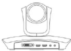
- Cable Hub
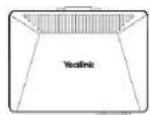
• L-Bracket (for installing the VC110 all-in-one unit)

• Velcro×2 (one Velcro is on the bracket)

• Mounting Accessories (for installing the VC110 all-in-one unit)
Expansion bolts

Screws(Specificaiton: T4×30)

Screws(Specificaiton: M3×8)

• VCR10 Remote Control

• AAA Batteries×2

- Power Adapter
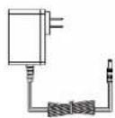
- Cables

DVI Cable

HDMI-VGA Direct Cable

HDMI Cable
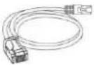
Ethernet Cable (2m)
- Cable Ties×5

• VC110 Quick Start Guide

VCM60 Package
• VCM60 Video Conferencing Wireless Microphone

- Power Adapter

- USB Cable

- Dongle

• VCM60 Quick Start Guide

VCP40 Package
• VCP40 Video Conferencing Phone

- Ethernet Cable (7.5m)

Locate the Audio In port of the cable hub, and connect it to the Audio Out port of the VCP40 with the 7.5m Ethernet cable. VCP40 video conferencing phone can work as an audio device for the VC110 endpoint. You can also place calls, answer calls or view directory and history on the VCP40 video conferencing phone.
VCP41 Package
• VCP41 Video Conferencing Phone

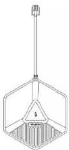
- Expansion Microphone CPE80×2
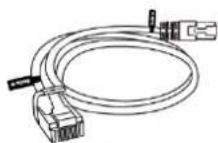
- Ethernet Cable (7.5m)
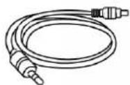
• 3.5mm Audio Cable (for connecting a PC/Mobile device to the VCP41)
Locate the Audio In port on the cable hub, and connect it to the Audio Out port of the VCP41 video conferencing phone with the 7.5m Ethernet cable. VCP41 Video conferencing phone can work as an audio device for the VC110 endpoint. You can also place calls, answer calls or view directory and history on the VCP41 video conferencing phone.
VCM30 Package
• VCM30 Video Conferencing Microphone Array
- Ethernet Cable (7.5m)

Locate the Audio In port of the cable hub, and connect it to the Audio Out port of the VCM30 with the 7.5m Ethernet cable. VCM30 video conferencing microphone array can work as the audio input device for the VC110 endpoint. For more information, refer to Audio Input Device on page 83.
Note
Check the list before installation. If you find that anything is missing, contact your system administrator.
Endpoint Component Instructions
Before installing and using the VC110 video conferencing endpoint, you need to be familiar with the following endpoint components, including:
• VC110 All-in-One Unit
- Cable Hub
• VCM60 Video Conferencing Wireless Microphone
• Video Conferencing Phone
• CPE80 Expansion Microphone
• VCM30 Video Conferencing Microphone Array
• VCR10 Remote Control
VC110 All-in-One Unit
The VC110 all-in-one unit integrates the camera, the built-in microphone and the codec into a unit. VC110 all-in-one unit compresses outgoing video and audio data, transmits this information to the far end, and decompresses incoming data. It supports 16:9 and 4:3 aspect ratios. It can be compatible with different audio output devices, and can adapt to the display devices automatically.
Lens cover
The lens cover is used for protecting the lens, which shall not receive dust pollution and all possible brush, collision.

The front of VC110 all-in-one unit
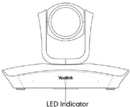
The HD camera supports 4x digital zoom, white balance and automatic gain. You can place the VC110 all-in-one unit on the table or mount it on a wall. The LED indicator in front of the camera indicates different statuses of the endpoint. For more information, refer to LED Instructions on page 23.
You can use the remote control to adjust the position or focus of the camera. The VC110 camera can be panned (± 100 degrees range), tilted (± 30 degrees range).


Infrared Sensor
The infrared sensor is located within the Yealink logo. Aim the remote control at the camera IR sensor to operate the unit.

Note
When the endpoint is powered on, avoid physically turning the camera. This may cause permanent damage to the camera. Always use the remote control to pan and tilt it.
The right side of the VC110 all-in-one unit

| Port Name | Description | |
| 1 | USB | Inserts a USB flash drive to one of the two USB ports for storing screenshots, recording videos or capturing packets.Inserts a dongle to one of the two USB ports for connecting the VCM60 video conferencing wireless microphone.Note:The wireless microphone dongle and USB flash drive can work at the same time.If two USB flash drives are connected, only the latter one can be identified. |
The left side of the VC110 all-in-one unit
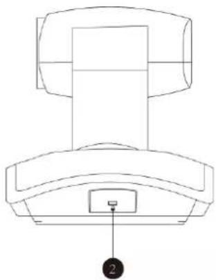
| Port Name | Description | |
| 2 | Security Slot | Allows you to connect a universal security cable to VC110 all-in-one unit, so you can lock it down. The endpoint cannot be removed when locked. |
The back of VC110 all-in-one unit

| Port Name | Description | |
| 3 | Reset Key | Resets the endpoint to factory defaults. |
| 4 | DVI Port | Connects to the cable hub. |
| 5 | Display1 | Connects to a display device for displaying video images.When connecting to only one display device, Display1 port on the VC110 all-in-one unit is the only available port. |
| 6 | Display2 | Connects to another display device for displaying video images. |
| 7 | Line In | Connects to an audio input device using an audio cable (3.5mm). |
| 8 | Line Out | Connects to an audio output device using an audio cable (3.5mm). |
Cable Hub
The front of cable hub:
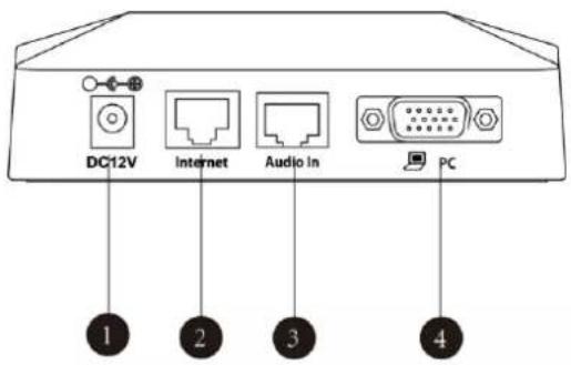
| Port Name | Description | |
| 1 | DC12V | Connects to the power source via a power adapter. |
| 2 | Internet | Connects to the network device. |
| 3 | Audio In | Connects to the video conferencing phone or the VCM30 video conferencing microphone array. |
| 4 | PC | Connects to a PC for sharing documents or videos during a call. |
The back of cable hub:
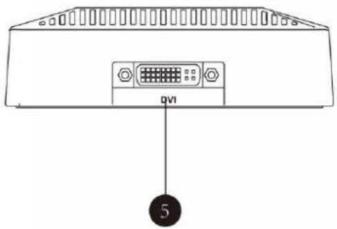
| Port Name | Description | |
| 5 | DVI Port | Connects to the VC110 all-in-one unit. |
VCM60 Video Conferencing Wireless Microphone
The VCM60 is a video conferencing wireless microphone which can work as the audio input device for VC110 video conferencing endpoint. It supports 360-degree audio pickup at a radius of up to 2 meters. There are a mute button and a battery indicator LED on its top. You can mute or unmute the VCM60 by tapping the mute button. There is a power switch on its bottom. You can turn off this switch if the VCM60 is not in use for a long period of time.

| Name | Description | |
| 1 | Battery Indicator LED | Indicates the battery information. For more information on the mute indicator LED, refer toLED Instructionson page 23. |
| 2 | Built-in Microphone | Supports 360-degree audio pickup at a radius of up to 2 meters. |
| 3 | Mute Button | Mutes or unmutes the VCM60. For more information on the mute indicator LED, refer toLED Instructionson page 23.Activates the VCM60 to search for the dongle when it is in the offline standby mode. For more information, refer toStandby Modeon page 23.Enters registration mode. For more information, refer toRegistering and Unregistering the VCM60on page 141. |
| 4 | Charging Interface | Connects the VCM60 to a power adapter or a computer's USB port using a USB cable to charge the VCM60. |
| 5 | Switch | Turns on or off the VCM60. |
For more information on how to use VCM60 video conferencing wireless microphone, refer to Using the VCM60 Video Conferencing Wireless Microphone on page 136.
Video Conferencing Phone
VCP40 Video Conferencing Phone
The VCP40 video conferencing phone supports 360-degree audio pickup to achieve ultra-HD voice.
Connect the VCP40 video conferencing phone to the cable hub. It can work as an audio device for the VC110. You can also place calls, answer calls or view directory and history on the VCP40 video conferencing phone.

Endpoint component instructions of the VCP40 video conferencing phone are:
| Item | Description | |
| 1 | LCD Screen | Shows information about calls, messages, soft keys, time, date and other relevant data:Call information-call durationIcons (for example,Missed call informationTime and date |
| 2 | Soft Keys | Label automatically to identity their context-sensitive features. |
| 3 | On-hook Key | Rejects or ends a call or returns to the previous screen. |
| 4 | Scrolls upwards through the displayed information. | |
| 5 | Enters list or answers incoming calls. | |
| 6 | Scrolls downwards through the displayed information. | |
| 7 | Keypad | Generates the digits and special characters "." "##". |
| 8 | Off-hook Key | Initiates a call or answers a call. |
| 9 | Presentation Key | Enables or disables presentation. |
| 10 | Mute Key | Toggles the mute feature. |
| 11 | Volume Key | Adjusts the volume of the speakerphone and ringer. |
| 12 | Microphone | Picks up voice. |
| 13 | LED Indicators | Indicate phone and call statuses. |
| 14 | Speakerphone | Provides ringer and hands-free (speakerphone) audio output. |
| 15 | MIC Port | Connects a CPE80 expansion microphone to one of two MIC ports. |
| 16 | Security Slot | Allows you to connect a universal security cable to lock down your phone. The phone cannot be removed when locked. |
| 17 | Audio Out Port | Connects to the video conferencing phone using the 7.5m Ethernet cable labeled Audio in.Provides the power supply for the video conferencing phone. |
VCP41 Video Conferencing Phone
The features of VCP41 video conference phone are similar to VCP40. For more information, refer to VCP40 Video Conferencing Phone on page 13. The only difference is that the back of VCP41 has a PC/Mobile port, which allows you to connect to an optional PC or Mobile Device, so that you can listen to the PC or mobile audio using your VCP41 video conferencing phone.
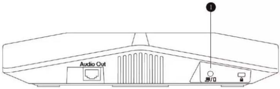
| Item | Description | |
| 1 | PC/Mobile Port | Allows you to connect an optional PC or Mobile Device to your phone so that you can listen to the PC or mobile audio using your VCP41 video conferencing phone. |
For more information on how to use VCP41 with the PC or mobile device, refer to Using VCP41 with the PC or Mobile Device on page 152.
CPE80 Expansion Microphone
If your video conferencing room is large, you can add extra CPE80 expansion microphones to the MIC ports on the video conferencing phone to expand the audio range.
Video conferencing phone has two MIC ports. Up to two expansion microphones can be connected to a video conferencing phone. CPE80 is a directional microphone. Its coverage range is a 120 degree. Always ensure that the speaker faces the expansion microphone.
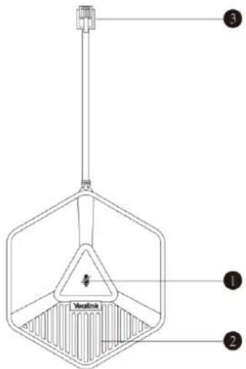
| Item | Description | |
| 1 | Mute Indicator LED | Toggles and indicates mute feature. |
| 2 | Microphone | Transmits sound to other phones. |
| 3 | MIC Connector | Allows you to connect to the MIC port on the video conferencing phone. |
VCM30 Video Conferencing Microphone Array
The VCM30 is a video conferencing microphone array which can work as the audio input device for VC110 video conferencing endpoint. It has 3 built-in microphones which support 360-degree audio pickup at a radius of up to 3 meters. There is a mute button on its top. You can mute or unmute the VCM30 by tapping the mute button during a call.
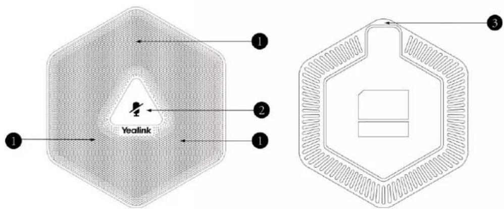
| Name | Description | |
| 1 | Built-in Microphones | Support 360-degree audio pickup at a radius of up to 3 meters. |
| 2 | Mute Button | Mutes or unmutes the VCM30. For more information on the mute indicator LED, refer toLED Instructionson page 23. |
| 3 | Audio Out Port | Connects to the Audio In port of cable hub using the 7.5m Ethernet cable labeled Audio In.Provides the power supply for the VCM30. |
For more information on how to use VCM30 video conferencing microphone array, refer to Using the VCM30 Video Conferencing Microphone Array on page 148.
VCR10 Remote Control
The VCR10 remote control provides 3 shortcut keys. It can help users to organize conference easily with intuitive and efficient operation in all screens.
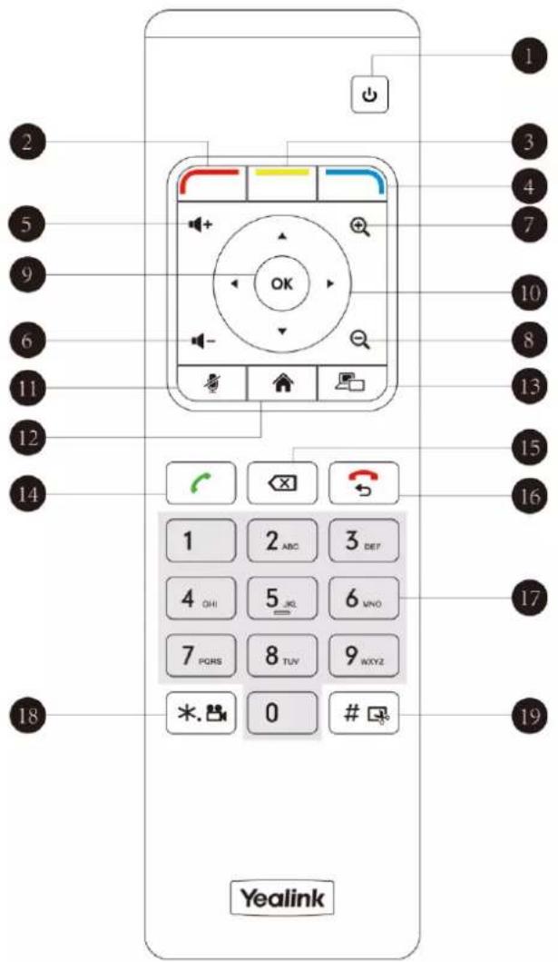
Hardware components of the remote control:
| Item | Description | |
| 1 | Sleep Key | Puts the endpoint to sleep or wakes the endpoint up. |
| 2 | Red Shortcut Key | Located at the bottom left of the screen. Label automatically identifies context-sensitive features.In the idle screen, this is used to enter the main menu screen and corresponds to the Menu soft key. |
| 3 | Yellow Shortcut Key | Located at the bottom center of the screen. Label automatically identifies context-sensitive features.In the idle screen, this is used to enter the pre-dialing screen, and corresponds to the Call soft key. |
| 4 | Blue Shortcut Key | Located at the bottom right of the screen. Label identifies context-sensitive features.In the idle screen, this is used to save and check the camera preset position, and corresponds to the Preset soft key. |
| 5 | Vol+ | Increases the endpoint volume. |
| 6 | Vol- | Decreases the endpoint volume. |
| 7 | Zoom in Key | Increases the camera zoom or the captured image magnifications.Behaves as page up in a multiple page list. |
| 8 | Zoom out Key | Decreases the camera zoom or the captured image magnifications.Behaves as page down in a multiple page list. |
| 9 | OK Key | Confirms actions or answers incoming calls. |
| 10 | Navigation Key | In the menu screen, press ▲ ▶to change menus, press ▲or ▼ to select items.In the idle screen, pan and tilt the camera to adjust the viewing angle. |
| 11 | Mute Key | Toggles the mute feature. |
| 12 | Home Key | Returns to the idle screen when in the menu screen.Enters the pre-dialing screen during a call. |
| 13 | Video Source Key | Switches the input source between Camera, Camera-PC, or PC. |
| 14 | Off-hook Key | Enters the pre-dialing screen.Places a call.Answers a call. |
| 15 | Delete key | Deletes one character at a time.Long press to delete all characters in the input field.Long press it for 2 seconds to start capturing packets and long press it for 2 seconds again to stop capturing packets. |
| 16 | On-hook Key | Ends a call or exits from a conference call.Returns to the previous screen when not in a call. |
| 17 | Keypad | Enters digits.Long press0to generate a special character “@” in the input fieldEnters the pre-dialing screen.Stores the preset position of the camera. |
| 18 | Video Recording Key | Generates a special characters “.”On the idle screen, press*,#to start/stop recording video.During a call, long press*,#to start/stop recording video. |
| 19 | Snapshot Key | Generates a pound key (#).On the idle screen, press#to capture the image from the camera.During a call, long press#to capture the image from the camera. |
Icon Instructions
Icons on Display Device
Icons appearing on the display device are described in the following table:
| Icon | Description |
 (flashing) (flashing) | Network is disconnectedNetwork is available |
 | Packet loss |
 | SIP account is registered |
 | H.323 account is registered |
 | Log into the Yealink VC Cloud Management Service/Yealink Meeting Server |
 | Log into the StarLeaf/Zoom/Pexip/BlueJeans/ Mind platform |
 | Auto answer |
 | Missed calls (this icon displays on the status bar) |
 | Volume is 0 |
 | Do not disturb |
 | Do not disturb during a call |
 | PC/Mobile mode (when a PC or mobile device is connected to the VCP41) |
 | Dongle is connected, while the VCM60 is unregistered |
 | Dongle is connected, and the VCM60 is registered |
 | The VCM60 is charging |
 | The standby time of VCM60 is less than one hour |
 | Dual screen mode |
 | Dual video sources (when a PC is connected to the PC port on the cable hub) |
 | A USB flash drive is inserted to the USB port of the VC110 all-in-one unit |
 | VPN is enabled |
 | Call mute |
 | Call encryption |
 | Call Hold |
 | Output volume is 0 during a call |
 | Camera that being controlled |
 | Indicates the content displayed on the second display device |
 | Camera position |
 | Record a video |
 | Dialed calls (H.323 account/SIP account/IP Call) |
 | Dialed calls (Cloud platform) |
 | Received calls (H.323 account/SIP account/IP Call) |
 | Received calls (Cloud platform) |
 | Missed calls (H.323 account/SIP account/IP Call) |
 | Missed calls (Cloud platform) |
 | Local contact |
 | Yealink Cloud contact or YMS contact |
 | Permanent Virtual Meeting Room |
Icons on Video Conferencing Phone
Icons appearing on the video conferencing phone are described in the following table:
| Icon | Description |
(Flashing) | Network is unavailableSIP account is registered (the icon flashes when it is not registered successfully) |
 | H.323 account is registered (the icon flashes when it is not registered successfully) |
 | Log into the Yealink VC Cloud Management Service/Yealink Meeting Server |
 | Log into the StarLeaf/Zoom/Pexip/BlueJeans/ Mind platform |
 | Auto answer |
 | Do not disturb |
 | Call is muted |
 | Volume is 0 |
 | A USB flash drive is inserted to the port of the VC110 all-in-one unit |
| [7HZK] | Record a video |
 | Local contact |
 | Yealink Cloud contact or YMS contact |
| V | Permanent Virtual Meeting Room |
 | Dialed calls (H.323 account/SIP account/IP Call) |
 | Dialed calls (Cloud platform) |
 | Received calls (H.323 account/SIP account/IP Call) |
 | Received calls (Cloud platform) |
 | Missed calls (H.323 account/SIP account/IP Call) |
 | Missed calls (Cloud platform) |
 | PC/Mobile mode (when a PC or mobile device is connected to the VCP41) |
LED Instructions
Indicator LED on the VC110 all-in-one unit:
| LED Status | Description |
| Solid green | The VC110 is powered on. |
| Solid red | The VC110 is in sleep mode. |
| Solid orange | The VC110 is abnormal (e.g., network unavailable, update failure). |
| Flashing green | Press the key on the remote control. |
| Off | The VC110 is powered off, or is not connect to the power adapter. |
Indicator LED on the video conferencing phone:
| LED Status | Description |
| Solid red | The phone is initializing.The video conferencing phone is muted when the VC110 is during a call. |
| Flashing red | The phone is ringing. |
| Solid green | The phone is placing a call.There is an active call on the phone. |
| Off | The phone is not connected to the cable hub.The phone is idle. |
Battery indicator LED on the VCM60 video conferencing wireless microphone:
| LED Status | Description |
| Solid green | The VCM60 is turned on within the first 5 seconds.The battery capacity reaches 100% during charging. |
| Flashing red | The battery capacity can maintain less than 1 hour. |
| Flashing green | The VCM60 is charging. |
| Off | Other status. |
Mute indicator LED on the VCM60 video conferencing wireless microphone:
| LED Status | Description |
| Fast flashing green | The VCM60 is searching for the dongle. |
| Green and in breathing state | The VCM60 registers with the dongle, and then enters the online standby mode. |
| Solid green | The VC110 is placing a call.The VC110 is in a call. |
| Solid red | The VC110 is muted during a call. |
| Fast flashing orange | The VCM60 enters registration mode. |
| Slowly flashing orange | The VCM60 fails to search for the dongle, and then enters the offline standby mode. |
| Off | The VCM60 is turned off.The VCM60 runs out of battery. |
Mute Indicator LED on the VCM30 video conferencing microphone array:
| LED Status | Description |
| Solid red | The VCM30 is muted when the VC110 is during a call. |
| Flashing red | The VC110 is ringing. |
| Solid green | The VCM30 is connected to the cable hub within the first 5 seconds.The VC110 is placing a call.The VCM30 is unmuted when the VC110 is during a call. |
| Off | The VCM30 is not connected to the cable hub.The VCM30 is idle. |
User Interfaces
There are two ways to customize the configurations of your VC110 video conferencing endpoint:
- Web User Interface
- Remote Control
Note
The display device and remote control constitute the endpoint user interface. This allows the user to execute all call operation tasks and basic configuration changes directly. Detailed operational steps will be explained in the feature section.
Web User Interface
You can customize your endpoint via the web user interface. To access the web user interface, you need to know the IP address of your new endpoint.
To obtain the IP address, do one of the following:
- The IP address of the endpoint is shown on the top right corner of the display device.
- Press (Menu soft key) on your remote control and select Status ->Network.
The display device shows network information about the endpoint.
- Press OK on the video conferencing phone when the phone is idle and select Network.
The LCD screen of the phone displays the network information of the endpoint.
Log into the web user interface:
- Enter the IP address (e.g., http://192.168.0.10 or 192.168.0.10) in the address bar of a web browser on your PC, and then press the Enter key.
- Enter the administrator user name and password.
The default user name is "admin" (case-sensitive), and the default password is "0000".
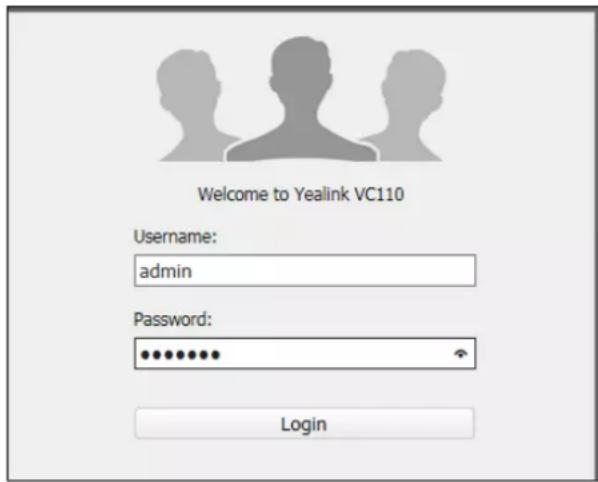
3. Click Login.
After you log into the web user interface successfully, you can click Logout on the top right corner of the web interface to log out.
Remote Control
You can use the remote control and display device to configure and use the VC110 video conferencing endpoint. The Advanced option is only accessible to the administrator. The default administrator password is "0000".
- For more information on the function of each key on the remote control, refer to VCR10 Remote Control on page 17.
- For more information on how to view menu settings on the display device, refer to Navigating Menus on the Display Device on page 42
- For more information on how to enter and edit the menu settings on the display device, refer to Entering Data and Editing Fields on page 44.
- You can also use virtual remote control on the web user interface to configure the VC110 video conferencing endpoint. For more information, refer to Virtual Remote Control on page 48.
Getting Started
This chapter provides the following basic installation instructions and information for achieving the best performance from your VC110 video conferencing endpoint. Topics include:
• Endpoint Connection and Installation
• Powering the Endpoint On or Off
- Setup Wizard
- Registration
- Idle Screen Display
- Navigating Menus on the Display Device
- Keyboard Input Method
- Entering Data and Editing Fields
- Endpoint Status
If you require additional information, or assistance to help you use your new phone, contact your system administrator.
Endpoint Connection and Installation
This section introduces the following:
- Connecting the VC110 video conferencing endpoint
- Installing the VC110 video conferencing endpoint
• Installing batteries in the remote control
Note
Up to two display devices can be connected to the VC110 all-in-one unit. Because the display device is not included in the package, you need to purchase it separately if required. Ensure that the purchased display device supports HDMI input.
When connecting only one display device to the VC110 all-in-one unit, Display1 port is the only available port. If dual screen mode is required, you can connect another display device to the Display2 port.
Because DVI cable is tailor-made, please use the Yealink-supplied DVI cable.
To prevent shock, do not connect the power adapter and turn on the power before connecting all endpoint components.
Connecting the VC110 Video Conferencing Endpoint
Do the following:
- Locate the DVI port on the back of the VC110 all-in-one unit, and connect it to the DVI port of the cable hub with the supplied DVI cable.
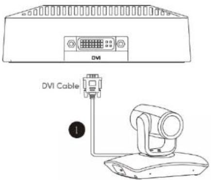
- Locate the Display1 port of the VC110 all-in-one unit, and connect it to the HDMI port on the display device with the supplied HDMI cable (Make sure the display device is powered on).

-
Locate the Internet port on the cable hub, and connect it to the port on the in-line power switch/hub with the supplied 2m Ethernet cable.
-
(Optional.) Locate the Audio In port of the cable hub, and do one of the following:
- Connect it to the Audio Out port on the video conferencing phone with the 7.5m Ethernet cable that labeled Audio In, and then connect the free end of the expansion microphone cables to MIC ports on the video conferencing phone.
- Connect it to the Audio Out port of the VCM30 video conferencing microphone array with the 7.5m Ethernet cable labeled Audio In.
-
(Optional.) Locate the PC port of the cable hub and connect it to the HDMI port on the PC with the supplied HDMI-VGA direct cable for sharing content.
-
Locate the DC19V port of the VC110 all-in-one unit, and connect it to an AC power outlet
with the supplied power adapter and power cord.
The cable hub also can be powered from a PoE-compliant switch or hub. For more information, refer to on Power over Ethernet on page 34.
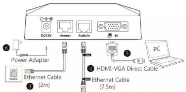
Connect to a Video Conferencing Phone or VCM30 audio device

You can fasten all cables with cable ties after all devices are connected.
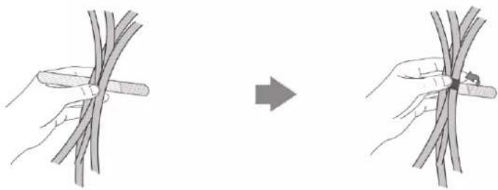
Installing the VC110 Video Conferencing Endpoint
Installing the Cable Hub
You can hang the cable hub on the wall. To use this method, you need to purchase the screws (specification: T4×30) separately.

Installing the VC110 All-in-one Unit
You can choose to mount the VC110 all-in-one unit on your TV or a wall, depending on your actual needs.
a) Mounting the VC110 all-in-one unit on a TV
When the thickness of your TV is between 35-120 mm, you can mount the VC110 all-in-one unit on your TV.

Do the following:
- Lock the VC110 all-in-one unit to the L-bracket.
- Remove one Velcro.
- Put the L-bracket on the top of the TV.
- Stick a Velcro onto the back of the TV, and make sure that the bracket and the back of the TV are tightly positioned against each other.
b) Mounting the VC110 all-in-one unit on a wall
You can also decide to mount the VC110 all-in-one unit on a wall. The recommended height for VC110 all-in-one unit positioning is 1.5m-1.8m above the ground.
Do the following:

- Punch holes into the wall and then insert the expansion bolts. Installation location for the expansion bolts and punching requirement are shown above.
- Lock the L-bracket with the M3×8 screws.
- Move the setscrews on the L-bracket to the left holes.
-
Lock the L-bracket to the wall with T4×30 screws.
-
Connect one end of the DVI cable to the VC110 all-in-one unit and put the other end of the DVI cable through the L-bracket.
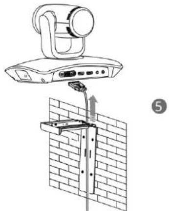
- Lock the VC110 all-in-one unit to the L-bracket, and then connect the other end of the DVI cable to the cable hub.

Installing Batteries for the Remote Control
Do the following:
- Open the battery cover on the back of the remote control.
-
Insert the batteries with the correct polarity.
-
Replace the battery cover.
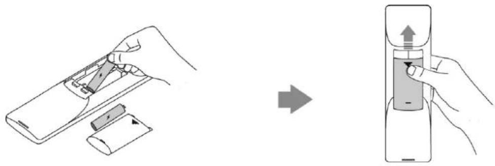
Remote Control Battery Safety Information
- Never make wrong polarity connection when charging and discharging battery packs.
- Avoid crushing, puncturing, or putting a high degree of pressure on any battery, as this can cause an internal short-circuit, resulting in overheating.
- Remove the batteries if they are not in use for long period of time. Battery leakage and corrosion can damage the remote control, dispose batteries safely.
- Do not dispose used batteries in domestic waste. Dispose batteries at special collection points or return to stores if applies.
- Do not dispose batteries in a fire.
Powering the Endpoint On or Off
You have two options for power and network connections. Your system administrator will advise you which one to use.
- AC power (Optional.)
• Power over Ethernet (PoE)
AC Power (Optional)
To connect the AC power:
-
Locate the DV12V port on the cable hub, and connect it to the electrical power outlet with the supplied power adapter.
-
Locate the Internet port on the cable hub, and connect it to the internet port on the wall or on the switch/hub device with the supplied 2m Ethernet cable.

Note
The VC110 video conferencing endpoint should be used with Yealink original power adapter (12V/2A) only.
Power over Ethernet
With the included or a regular Ethernet cable, the VC110 video conferencing endpoint can be powered from a PoE-compliant switch or hub.
To connect the PoE:
- Locate the Internet port on the cable hub, and connect it to the port on the in-line power switch/hub with the Ethernet cable.

IEEE 802.3af compliant PoE Hub/Switch
Note
If in-line power is provided, you don't need to connect the cable hub to the power adapter. Make sure the switch/hub is PoE-compliant.
Important! Do not remove power from the cable hub while it is updating firmware and configurations.
Remove power to power off the endpoint if long time no use.
Setup Wizard
When you first start up or reset the endpoint, the display device will display the setup wizard.
To configure the setup wizard via the remote control:
- Set the language displayed on the display device.
The default language is English.

- Press (Next soft key) to continue.
3. Set the date and time.
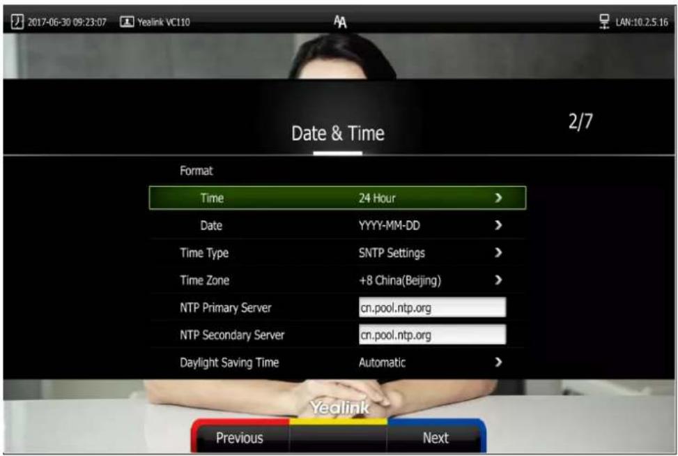
- Press (Next soft key) to continue or press (Previous soft key) to return to the previous screen.
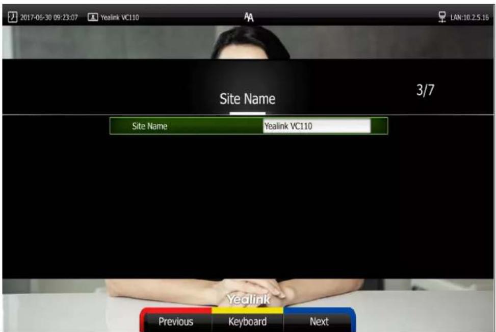
5. Edit the site name.
The default site name is "Yealink VC110".
-
Press (Next soft key) to continue or press (Previous soft key) to return to the previous screen.
-
Change the administrator password.
The default administrator password is "0000".

Note
Do remember the new administrator password or keep a copy of the password in a safe place. If you forget the password, you will need to reset the endpoint to the factory settings, and then reset the password or use the default password "0000".
- Press 📄 (Next soft key) to continue or press 📄 (Previous soft key) to return to the previous screen.
The display device shows firewall port mapping information.

- Press (Next soft key) to continue or press (Previous soft key) to return to the
previous screen.
10. Configure network settings.
The phone will attempt to contact a DHCP server in your network to obtain an IP address, subnet mask, default gateway address and DNS address by default. If you uncheck the DHCP checkbox, you will then need to configure IPv4 or IPv6 network manually.

-
Press 📄 (Next soft key) to continue or press 📄 (Previous soft key) to return to the previous screen.
-
(Optional) Log into the Cloud platform.
Yealink video conferencing endpoint supports Yealink VC Cloud Management
Service/Yealink Meeting Server/StarLeaf/Zoom /Pexip/BlueJeans/Mind/Custom platform.
For more information, refer to
Yealink_VC110_All_in_one_HD_Video_Conferencing_Endpoint_Administrator_Guide

- Press (Complete soft key) to complete the setup wizard.
For more information on how to configure endpoint features using the remote control, refer to Navigating Menus on the Display Device on page 42 and Entering Data and Editing Fields on page 44. For more information on how to configure language, time and date, refer to
Customizing the VC110 Video Conferencing Endpoint on page 48.
Note
Wrong network settings may result in the inaccessibility of your endpoint. They may also have an impact on your network performance. For more information on these parameters, contact your system administrator.
Controlling Local Camera
Before placing a video call, you need to be familiar with how to adjust the angle and focus of the camera. Avoid physically adjusting the camera to prevent damaging it. Always use the remote control to control the camera.
To control local camera via the remote control:
- Press the navigation key to adjust the angle of the camera.
- Long press - or + to adjust the focus of the camera.
Registration
You can register the H.323 account, SIP account and log into Cloud platform (Yealink VC Cloud Management Service/Yealink Meeting Server/StarLeaf/Zoom/Pexip/BlueJeans/Mind/Custom platform). Generally, your system administrator will configure the account beforehand, so that after you start up the endpoint, the endpoint will already be registered and ready for use. If your endpoint is not registered, you may have to register it. For more information on how to register an account for the endpoint, refer to Yealink VC110 All-in-one HD Video Conferencing Endpoint Administrator Guide.
Idle Screen Display
Idle screen of the display device
If the endpoint starts up, the idle screen will be shown. The following figure shows an example of the idle LCD screen:

| Name | Description |
| Time and Date | The phone's time and date are displayed on the left of the status bar. |
| Site name | The site name of the endpoint.For more information on how to change the site name,refer to Site Name on page 51. |
| Status icon | Status icons are displayed in the center of the status bar. For more information on the status icon, refer to Icons on Display Device on page 19. |
| IP address | LAN: X.X.X.X: Indicates the endpoint has obtained an IP address.Network disconnected: Indicates the endpoint does not connect to an Ethernet cable. Please check the Ethernet cable.255.255.255.255: Indicates the endpoint fails to obtain an IP address. Check the connection between the endpoint and the DHCP server, or you can configure a static IP address for the endpoint. For more information on how to configure a static IP address, refer to Setup Wizard on page 35. |
| Registered account | When the VC110 endpoint is registered with the SIP server, the account icon isSIP. For more information, refer toYealink_VC110_All_in_one_HD_Video_Conferencing_End point_Administrator_Guide. |
| When the VC110 endpoint is registered with an H.323 gatekeeper, the account icon isH323. For more information, refer toYealink_VC110_All_in_one_HD_Video_Conferencing_End point_Administrator_Guide. | |
| When the VC110 endpoint logs into Yealink VC Cloud Management Service/Yealink Meeting Server, the icon isVC.When the VC110 endpoint logs into StarLeaf/Zoom/Pexip/BlueJeans/Mind platform, the icon isFor more information, refer to Yealink VC110 All-in-one HD Video Conferencing Endpoint Administrator Guide. | |
| Video image | Video image is displayed. |
| Soft keys | The display device shows the names of shortcut keys, and users can press these shortcut keys on the remote control to execute corresponding action. |
Idle screen of the video conferencing phone

| Name | Description |
| Status icon | Displays the phone's status icon. |
| Soft Keys | Displays four soft keys.History:Enters the History screen.Directory:Enters the Directory screen.DND:Enables or disables the Do Not Disturb mode.Redial:Redials the last dialed number. |
| Site name | Displays the site name. |
| Time and Date | Displays the time and date. |
Navigating Menus on the Display Device
You can use the remote control to enter the main menu screen, and view the items on the display device.
Note
The endpoint will automatically return to the idle screen after 60 seconds of inactivity.
To navigate menus and fields, you can:
| If you want to | You can |
| Enter the main menu. | Press [IMAGE] (Menu soft key). |
| Return to the idle screen. | Press [IMAGE]. |
| Go back to the previous menu. | Press [IMAGE] (Back soft key) or [IMAGE]. |
| Navigate through menus. | Press ◀ or ▶ to select a menu.Press ▲ or ▼ to select an item. |
| Expand pull-down list. | Press [IMAGE] or ▶ to expand a pull-down list. |
| Select an option from the pull-down list. | From the pull-down list, Press ▲ or▼ to scroll to the settings and then press OK . |
| Enable or disable features. | Press OK . |
Keyboard Input Method
The on-screen keyboard supports English and Russian input methods.
You can enter characters using the input method only when the input method is enabled.
Changing keyboard input method is configurable via web user interface only.
To configure keyboard input method via web user interface:
-
Click on Setting ->General.
-
In the Keyboard IME block, select the desired list from the Disabled column and click → .
The selected input method appears in the Enabled column.
-
Repeat step 2 to add more input methods to the Enabled column.
-
(Optional.) To remove a list from the Enabled column, select the desired list and then click ← .
-
To adjust the display order of the enabled input methods, select the desired list, and click or ↓.


- Click Confirm to accept the change.
To change keyboard input method via the remote control:
-
In the editing field, press ☐ (Keyboard soft key) or ☐ (Keyboard soft key). The display device displays the on-screen keyboard.
-
Press (abc soft key) to change the input method.
Entering Data and Editing Fields
You can enter data and edit fields using the keypad on the remote control or the on-screen keyboard on the display device:
To enter or edit data:
- Select the field.
- Do one of the following:
| If you want to | You can |
| Entering numbers. | Press the digit keys on the remote control. |
| Entering letters. | 1. Press (Keyboard soft key) to open theon-screen keyboard. If the endpoint is in the dialing screen, press (Keyboard soft key) to open the on-screen keyboard.2. Press the navigation keys on the remote control to select desired letters.3. Press (abc soft key) to change input method.4. Press OK.5. Press (Exit Keyboard soft key) to exit from the on-screen keyboard. |
| Entering special characters. | 1. Press (Keyboard soft key) to open the on-screen keyboard. If the endpoint is in the dialing screen, press (Keyboard soft key) to open the on-screen keyboard.2. Press (abc soft key) to switch the input method to @#%.3. Press the navigation keys on the remote control to select desired characters.4. Press OK.5. Press (Exit Keyboard soft key) to exit from the on-screen keyboard. |
| Delete text you entered. | Press to delete one character at a time.Long press for 2 seconds to delete the entire field of text. |
- Press to save.
Endpoint Status
When the endpoint is idle, you can view its status via the remote control, video conferencing phone or web user interface.
Available endpoint status information includes:
• System information (device model, firmware, hardware version and product ID)
- Network status (LAN type, IP address, MAC, subnet mask, gateway and DNS server, public IP address can also be viewed if the static NAT is enabled)
• Account status (register status of Cloud platform, SIP account and H.323 account)
• Camera (status, device model, SPEC and hardware version)
• Audio (the active audio input and output devices)
• VCS Phone (status, device model, hardware version and serial number)
• Wired Micpod (status, model, hardware, serial number)
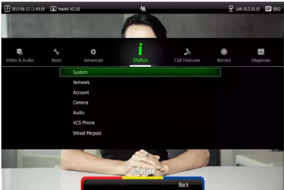
To view the endpoint status via the remote control:
1. Press (Menu soft key).
The display device shows the Status menu.
-
Press ▲ or ▼ to select the desired list.
-
Press OK to view the specific information.
To view the endpoint status via the web user interface:
- Click Status.
The endpoint status is displayed on the web user interface.

To view the endpoint status via phone user interface:
- Press OK.
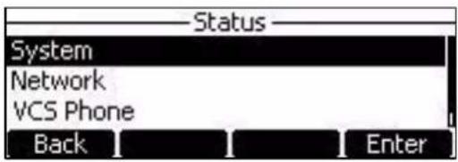
- Press □ or ▼ to select the desired list.
- Press OK or the Enter soft key to view the specific information.
Customizing the VC110 Video Conferencing
Endpoint
You can customize your VC110 video conferencing endpoint by personally configuring certain settings, for example, site name, time & date and language. You can add contacts to the local directory manually or from the call history.
This chapter provides basic operating instructions for customizing your endpoint. Topics include:
- General Settings
- Directory
- Call History Management
- Call Protocol
- Bandwidth Settings
- Audio Settings
• Far-end Camera Control
If you require additional information or assistance with your new endpoint, contact your system administrator.
General Settings
Virtual Remote Control
In addition to using the remote control, you can also control the VC110 video conferencing endpoint via virtual remote control.
To control endpoint via the virtual remote control:
- Click Home->Remote Control when the endpoint is idle or during a call.

- Click the keys on the virtual remote control to control the endpoint.
- Click Remote Control to hide the virtual remote control.
Automatic Sleep Time
The endpoint will enter the sleep mode automatically when it has been inactive for a period of time (the default period is 10 minutes).
When the endpoint is in sleep mode, it will still accept incoming calls. The display device will prompt "No Signal", and the video conferencing phone LCD screen prompts "Sleeping Press any key to resume". You can press any key on the remote control or video conferencing phone to wake the endpoint up. When receiving a call, the endpoint will be woken up automatically.
You can change the automatic sleep time via the remote control or web user interface. You can also press the sleep key on the remote control to make the endpoint sleep immediately.
To configure the automatic sleep time via the remote control:
-
Press (Menu soft key) to enter main menu.
-
Press ◀ or ▶ to select the Basic menu.
-
Press ▲ or ▼ to scroll to Automatic Sleep Time, and then press OK.
-
Select desired time from the pull-down list of Automatic Sleep Time.
If Always On is selected, the endpoint will not enter the sleep mode automatically.

- Press (Save soft key) to accept the change.
Automatic sleep time is configurable via the web user interface at the path
Setting->General->Automatic Sleep Time.
Backlight
The backlight of the video conferencing phone is always on by default. You can configure backlight time for the video conferencing phone's LCD screen via the web user interface.
You can configure the LCD screen's backlight time in the following formats:
• Always On: Backlight is on permanently.
- 15s, 30s, 1Min, 2 Min, 5 Min, 10 Min, 30 Min: Backlight goes out when the phone has been inactive for the time you set.
To configure the backlight of the video conferencing phone via the web user interface:
- Click on Setting->General.
- Select the desired value from the pull-down list of Backlight Time.

- Click Confirm to accept the change.
Site Name
Site name is displayed on the status bar of the display device and video conferencing phone.
You can make an IP address call to the other party, the endpoint site name will be displayed on the remote display device. Site names can consist of letters, numbers or special characters.
Site name is configurable via the remote control or web user interface.
To configure the site name via the remote control:
- Press (Menu soft key) to enter main menu.
- Press ◀ or ▶ to select the Basic menu.
- Press ▲ or ▼ to scroll to Site Name.
4. Edit the site name.
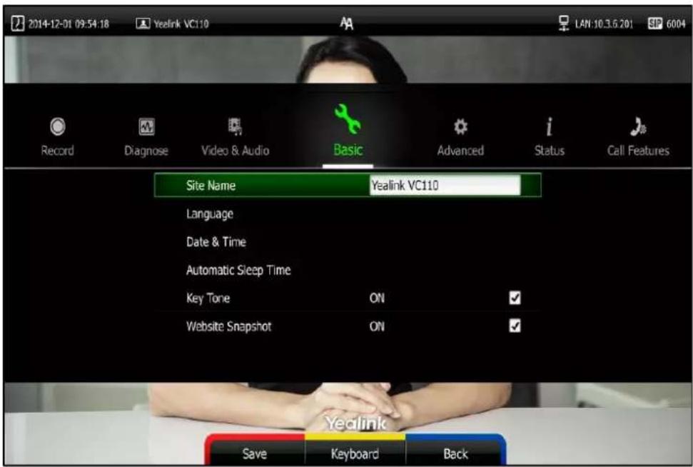
- Press (Save soft key) to accept the change.
Site name is configurable via the web user interface at the path Setting->General->Site Name.
Language
The default language of the display device is English, and you can change it via the remote control. The video conferencing phone will detect and use the same language as which of the display device.
The default language of the web user interface is English. You can change the web user interface language via web user interface. The available languages for the endpoint are English, Chinese Simplified, Chinese Traditional, French, German, Italian, Polish, Portuguese, Spanish, Turkish, Russian and Czech.
To change the language on the display device via the remote control:
- Press (Menu soft key) to enter main menu.
- Press ◀ or ▶ to select the Basic menu.
-
Press ▲ or ▼ to scroll to Language, and then press OK.
-
Select the desired language from the pull-down list of Language.
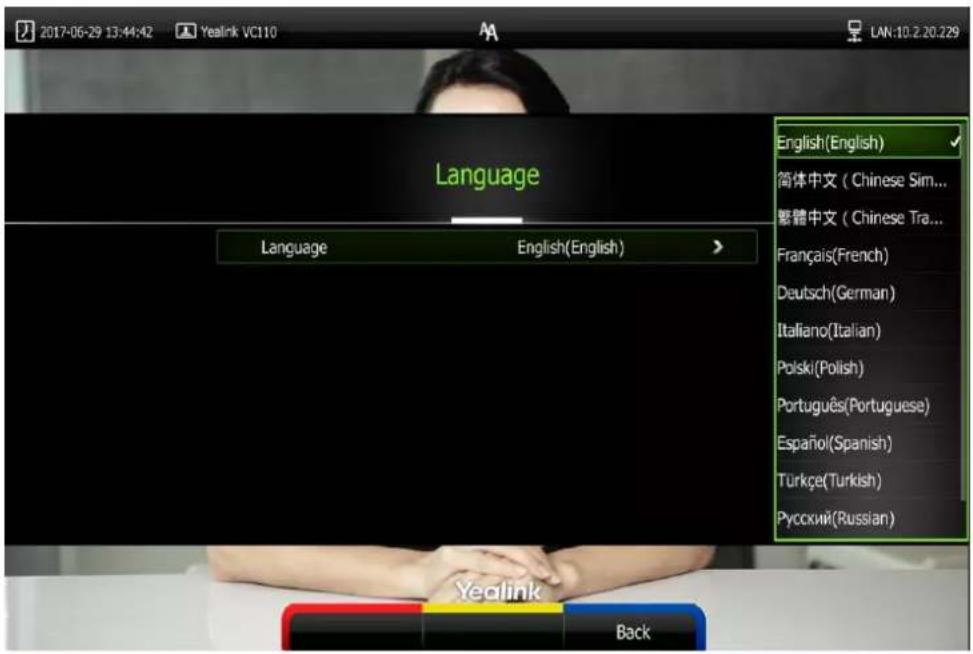
- Press (Save soft key) to accept the change.
Text displayed on the display device and LCD screen of video conferencing phone will change to the selected language.
To change the language for the web user interface:
- Click on Language at the top right corner of the web page.
- Select the desired language from the pull-down list of Language.

Text displayed on the web user interface will change to the selected language.
Date & Time
The time and date are displayed on the LCD screen of the video conferencing phone and display device. You can configure the endpoint to obtain the time and date from the SNTP (Simple Network Time Protocol) server automatically. The SNTP allows the endpoint to synchronize time to a main server. This keeps all network machine clocks on the same time. Enter the NTP Server name that you want to follow.
If the phone cannot take the time and date from the SNTP server, you can configure the time and date manually, or contact your system administrator for more information.
There are 7 available date formats. For example, for the date format "WWW DD MMM", "WWW" represents the abbreviation of week. "DD" represents the two-digit day, and "MMM" represents the first three letters of the month.
The available date formats you need to know are:
| Date Format | Example (2017-5-23) |
| WWW MMM DD | Tue May 23 |
| DD-MMM-YY | 23-May-17 |
| YYYY-MM-DD | 2017-05-23 |
| DD/MM/YYYY | 23/05/2017 |
| MM/DD/YY | 05/23/17 |
| DD MM YYYY | 23 May 2017 |
| WWW DD MMM | Tue 23 May |
To configure the NTP server and date & time format via the remote control:
- Press (Menu soft key) to enter main menu.
- Press ◀ or ▶ to select the Basic menu.
- Press ▲ or ▼ to scroll to Date & Time, and then press OK.
- Select the desired time format from the pull-down list of Time.
- Select the desired date format from the pull-down list of Date.
- Select SNTP Settings from the pull-down list of Time Type.
- Select the time zone that applies to your area from the pull-down list of Time Zone. The default time zone is "+8 China(Beijing)".
- Enter the domain names or IP addresses in the NTP Primary Server and NTP Secondary Server fields respectively.
- Select the desired value from the Daylight Saving Time field.
When Automatic is selected, the endpoint will use daylight saving time corresponding to the selected time zone.
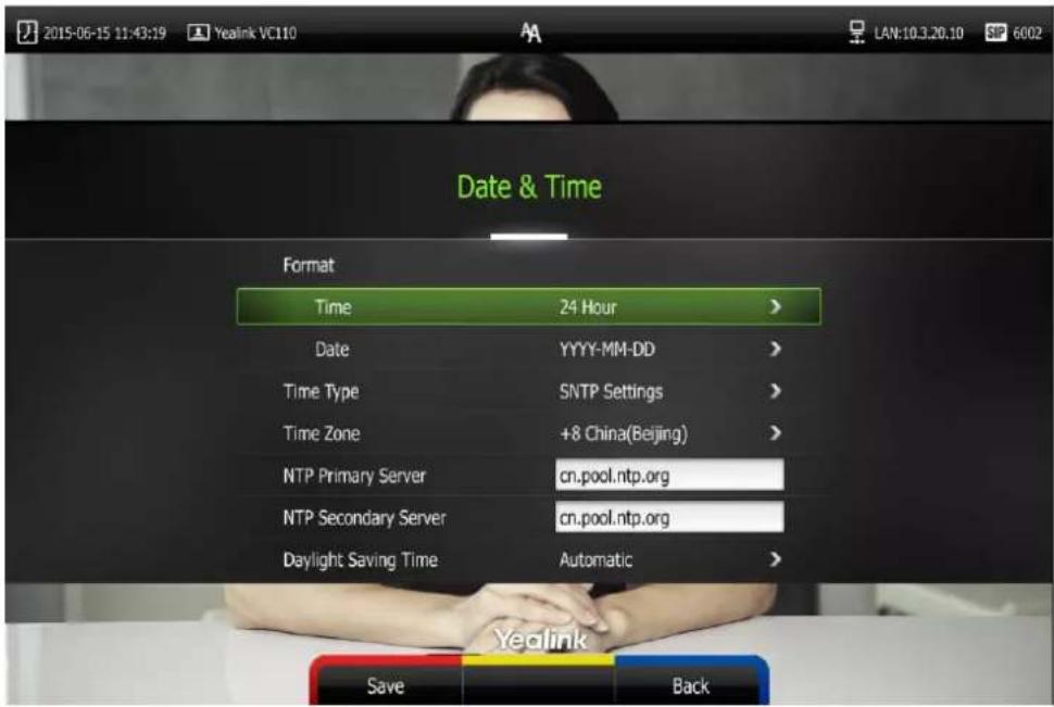
- Press (Save soft key) to accept the change.
Note
Please refer to Appendix A - Time Zones for the list of available time zones on the endpoint.
To configure the time and date manually via the remote control:
- Press (Menu soft key) to enter main menu.
- Press ◀ or ▶ to select the Basic menu.
- Press ▲or ▼ to scroll to Date & Time, and then press OK.
- Select the Manual Settings from the pull-down list of Time Type.
- Select the desired year from the pull-down list of Year.
- Select the desired month from the pull-down list of Month.
- Select the desired day from the pull-down list of Day.
- Select the desired hour from the pull-down list of Hour.
- Select the desired minute from the pull-down list of Minute.
10. Select the desired second from the pull-down list of Second.

11. Press (Save soft key) to accept the change.
Time and date is configurable via the web user interface at the path Setting-> Date&Time.
Key Tone
You can enable the key tone feature to play a key tone when you press the key on the remote control.
Key tone is configurable via the remote control or web user interface. Key tone feature is enabled by default.
Note
If ringer volume is adjusted to 0, you cannot hear the key tone. For more information on how to adjust the ringer volume, refer to Volume Settings on page 59.
To configure the key tone via the remote control:
-
Press (Menu soft key) to enter main menu.
-
Press ◀ or ▶ to select the Basic menu.
-
Press ▲ or ▼ to scroll to Key Tone, and then press OK to enable or disable this feature.
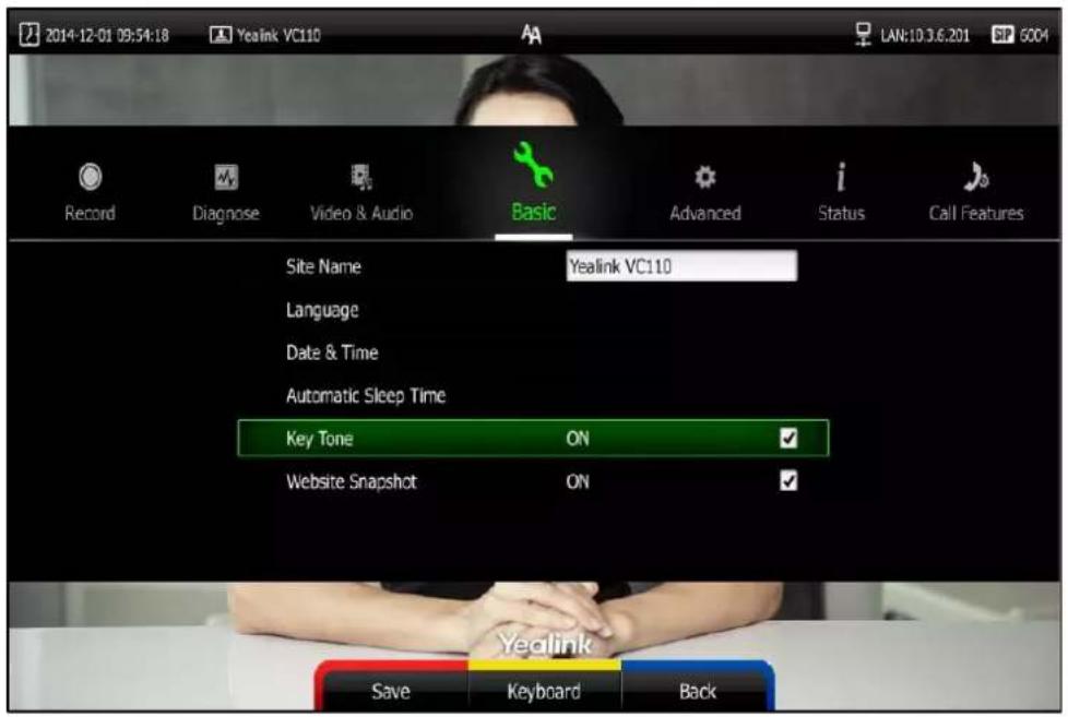
- Press (Save soft key) to accept the change.
Key tone is configurable via the web user interface at the path Setting->General->Key Tone.
Meeting Blacklist
You can add the IP address, account or domain name of the remote endpoint to the meeting blacklist. VC110 will refuse incoming calls from the blacklist automatically. VC110 will not remind incoming calls and save call history from blacklist.
VC110 supports up to 100 blacklist records. Blacklist is configurable via web user interface only.
To add the blacklist numbers via web user interface:
- Click on Directory->Meeting Blacklist.
- Enter the user's IP address, account or domain name in the Meeting Blacklist Number field.
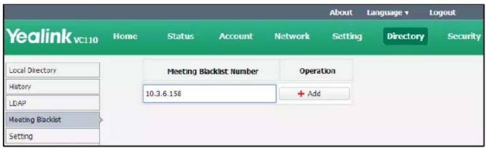
- Click Add.
- Repeat step 2-3 to add more numbers to the meeting blacklist.
To delete the blacklist numbers via web user interface:
- Click on Directory-> Meeting Blacklist.
- Click Delete beside the numbers that you want to delete.
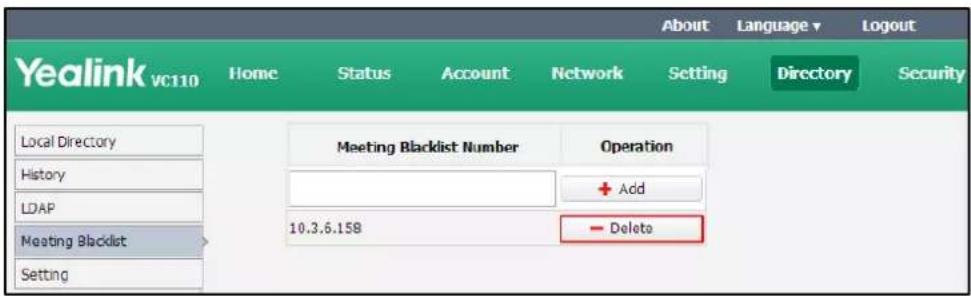
The web user interface prompts the message "Warning: Are you sure delete the black number?".
- Click Confirm.
Website Snapshot
You can enable the website snapshot feature to allow the user to watch video images captured by local camera on the web user interface.
Website snapshot is configurable via the remote control only and it is enabled by default.
To configure the website snapshot via the remote control:
- Press (Menu soft key) to enter main menu.
-
Press ◀ or ▶ to select the Basic menu.
-
Press ▲or ▼ to scroll to Website Snapshot, and then press OK to enable or disable this feature.

- Press (Save soft key) to accept the change.
To watch video images via the web user interface at the path Home.
Volume Settings
You can use the remote control or video conferencing phone to adjust the ringer volume of the endpoint when it is idle or ringing. You can also adjust the receiver volume of engaged audio devices when the endpoint is in use.
To adjust the volume when the endpoint is idle or ringing:
Do one of the following:
- Press 📋 – or 📋 + on the remote control to adjust the ringer volume of the endpoint.
The current ringer volume of the endpoint is displayed on the left of the display device.

- Press ☐ on the video conferencing phone to adjust the ringer volume. The LCD screen of the video conferencing phone displays the current ringer volume.
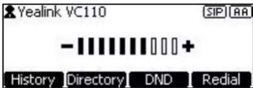
The display device will display the ringer volume simultaneously.
Note
If ringer volume is adjusted to 0, the 📋 icon will appear on the display device. The 🖱️ icon will appear on the LCD screen of the video conferencing phone.
To adjust the volume when the endpoint is during a call:
- Press ▶-or ▶+on the remote control to adjust the receiver volume of the endpoint.
The current receiver volume of the endpoint is displayed on the left of the display device.
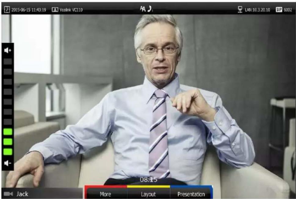
- Press - on the video conferencing phone to adjust the receiver volume.
The LCD screen of the video conferencing phone displays the current receiver volume.

The display device will display the receiver volume simultaneously.
Note
If the video conferencing phone is not the active audio device of the endpoint, you can still use it to adjust the endpoint volume.
Hiding Icons in a Call
During a call, the display device displays some icons to indicate the call status. You can hide these icons as needed to achieve the best video effects. Hiding icons in a call feature is configurable via web user interface only.
To hide icons in a call via web user interface:
- Click on Setting->General.
-
Select the desired values from the pull-down lists of Time Icon, Mute Icon, Camera Icon, Recording Icon, Sitename Icon, Hold Icon, Encrypt Icon, OutPut Mute Icon, and SecondScreen Icon.
-
If you select Disabled, the endpoint displays corresponding icons during a call.
- If you select Hide with UI, the endpoint displays corresponding icons during a call, but the icons will disappear when the operation menu is hidden automatically.
- If you select Enabled, the endpoint does not display corresponding icons during a call.
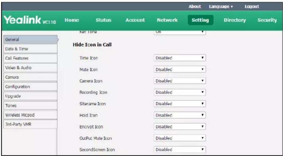
- Click Confirm to accept the change.
USB Configuration
If you have high requirement for data security, you can disable the USB feature. If you disable the USB feature, you cannot view the videos and screenshots stored in the USB flash driver via the remote control, and cannot record video or capture screenshots too.
To configure USB configuration via web user interface:
- Click on Setting-> Video & Audio.
2. Select the desired value from the pull-down list of USB Enable.

3. Click Confirm to accept the change.
Directory
VC110 endpoint can display: local contacts, Yealink Cloud contacts and YMS contacts.
- Local contacts: VC110 endpoint can store up to 500 local contacts. You can import or export local contact list to different endpoints to share the local directory. The endpoint only supports the XML and CSV format contact lists. You can view local directory via web user interface, remote control and the video conferencing phone. But you can edit or delete the local directory via web user interface and remote control.
- Yealink Cloud contacts: If you log into the Yealink VC Cloud Management Service platform, Yealink Cloud contacts which are created by your administrator, appear in your directory. Note that only the administrator can add, edit and delete Yealink Cloud contacts on the Yealink VC Cloud management service. On your VC110, you can only search for and place calls to the Yealink Cloud contacts. For more information on Yealink VC Cloud management service, refer to Yealink VC Cloud Management Service Administrator Guide.
- YMS contacts: If you log into the Yealink Meeting Server, enterprise directory which is created by your administrator, appears in your directory. Note that only the administrator can add, edit and delete the YMS contacts and permanent VMR on the Yealink Meeting Server (YMS). The administrator can also determine whether synchronize the permanent VMR to the VC110. On your VC110, you can only search for and place calls to the YMS
contacts and permanent VMR. For more information on Yealink Meeting Server, refer to Yealink Meeting Server Administrator Guide.
Note
Starleaf/Zoom/BlueJeans/Pexip/Mind platform does not provide Cloud contacts for video conferencing endpoint.
This chapter provides operating instructions for the directory. Topics include:
- Adding Local Contacts
- Placing Calls to Contacts
- Editing Local Contacts
- Deleting Local Contacts
- Searching for Contacts
- Search Source List in Dialing
- Importing/Exporting Local Contact Lists
Adding Local Contacts
You can add local contacts to the endpoint via the remote control or web user interface.
To add a local contact via the remote control:
- Press □ (Call soft key).
- Press ◀ or ▶ to select the Directory menu.
- Press (New Contact soft key).
- Enter contact name in the Name field.
- Enter contact number or IP address in the Number 1 field.
- Press ▲or ▼to scroll to Add New Number, and then press OK to add more numbers. Up to 3 numbers can be added to a local contact.
- Enter the second number of the local contact in the Number 2 field.
You can repeat the step 6 to add the third number to the local contact, and enter the third number in the Number 3 field.
8. Select the desired contact bandwidth from the pull-down list of Bandwidth.
The default contact bandwidth is Auto. The endpoint will select the appropriate bandwidth automatically.
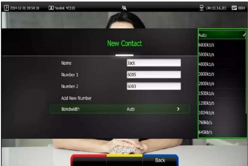
9. Press (Save soft key) to save the local contact.
Note
If the contact already exists in the directory, the display device will prompt "Contact already exists!".
You can also add local contacts via web user interface at the path Directory->Local Directory.
Placing Calls to Contacts
You can place calls to contacts via the remote control, video conferencing phone or web user interface.
To place a call to a contact via the remote control:
- Press □ (Call soft key).
- Press ◀ or ▶ to select the Directory menu.
- Select the desired contact type from the pull-down list of the All Contacts first.
- Press ▲ or ▼ to select the desired contact.
- Press OK.
- If only one number is stored for the contact, the contact number will be dialed out directly.
- If multiple numbers are stored for the contact, press ▲or ▼ to highlight the desired
number, and then press OK or 📞 to dial out the number.
To place a call to a contact via the video conferencing phone:
-
Press the Directory soft key to enter the Directory list.
-
Press ▲ or ▼ to select the desired directory list.
-
Press the Enter soft key or (OK) to view the contacts in the selected directory.
-
Press ▲ or ▼ to select the desired contact.
You can press the ◀ or ▶ soft key to change the directory list.
- Do one of the following:
- If only one number is stored for the contact, press the Send soft key, OK or to call the contact.
- If multiple numbers are stored for the contact, press the Enter soft key or OK to view the contact numbers.
- Press ▲ or ▼ to highlight the desired number.
- Press the Send soft key, OK or to call the contact.
You can also place calls to local contacts via the web user interface at the path
Directory->Local Directory.
Editing Local Contacts
You can only edit local contacts via the remote control or web user interface:
To edit a local contact via the remote control:
-
Press □ (Call soft key).
-
Press ◀ or ▶ to select the Directory menu.
-
Press ▲ or ▼ to select the desired local contact.
-
Press (Detail soft key).
-
Edit contact information.
You can select Add New Number to add new numbers for the local contact.
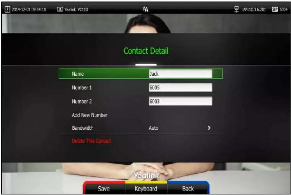
- Press (Save soft key) to accept the change or press (Back soft key) to cancel.
You can also edit local contacts via the web user interface at the path Directory->Local Directory.
Deleting Local Contacts
You can only delete local contacts via the remote control or web user interface.
To delete a local contact via the remote control:
- Press □ (Call soft key).
- Press ◀ or ▶ to select the Directory menu.
- Press ▲ or ▼ to select the desired local contact.
- Press (Detail soft key).
-
Press ▲ or ▼ to highlight the Delete This Contact, and then press OK. The display device prompts "Delete this contact?".
-
Press ▲ or ▼ to highlight OK.

- Press OK to delete this local contact.
You can also delete local contacts via the web user interface at the path Directory->Local Directory.
Searching for Contacts
You can search for local contacts via the remote control, video conferencing phone or web user interface.
If you log into the Yealink VC Cloud Management Service platform or Yealink Meeting Server, you can also search for Yealink Cloud contacts or YMS contacts via the remote control or video conferencing phone.
To search for contacts via the remote control:
-
Press □ (Call soft key).
-
Press ◀ or ▶ to select the Directory menu.
-
Press ▲ or ▼ to select the searching box.
You can select the desired contact type from the pull-down list of the All Contacts first.
- Enter a few or all characters of the contact name or numbers.
The contacts whose names or phone numbers match the characters entered will appear on the display device.

- You can press ▲ or ▼ to select the desired contact, and then call this contact.
Search Source List in Dialing
You can search for a contact from the desired lists when the phone is in the pre-dialing screen. The lists can be History, Local Directory, Cloud Contacts (including your Yealink Cloud contacts and YMS contacts) and LDAP.
In the pre-dialing screen, when you enter a few characters, the endpoint will search for the matched contacts from the enabled search source lists, and display the result in the dialing screen.
If you want to match the LADP list, make sure LDAP is configured already. For more information on how to configure LDAP, contact your system administrator.
To configure search source list in dialing via the web user interface:
-
Click on Directory->Setting.
-
In the Search Source List In Dialing block, select the desired list from the Disabled column and click →.
The selected list appears in the Enabled column.
-
Repeat step 2 to add more lists to the Enabled column.
-
(Optional.) To remove a list from the Enabled column, select the desired list and then click ← .
-
To adjust the display order of the enabled list, select the desired list, and click or ↓.
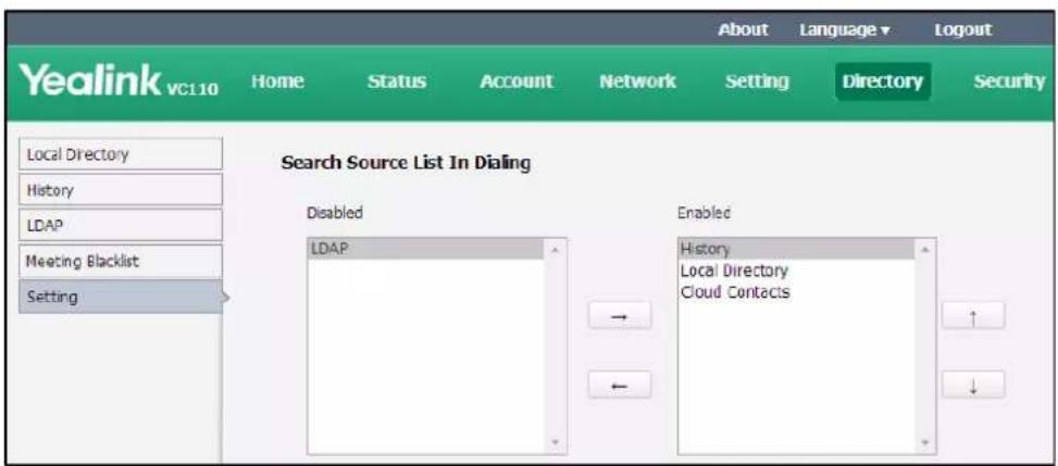
- Click Confirm to accept the change.
Note
Search source list in dialing is only configurable via the web user interface.
To place a call via search source lists:
-
Press □ (Call soft key).
-
Enter a few or all characters of the contact name or numbers.
The contacts whose names or phone numbers match the characters entered will appear on the display device.
- Press ▲ or ▼ to select the desired contact, and then press 📁 or OK to call the contact.

Importing/Exporting Local Contact Lists
You can import or export the local contact list to share local contacts between different endpoints or between endpoint and application software (e.g., Outlook).
The VC110 video conferencing endpoint only supports the XML and CSV format local contact lists. You can only import or export the local contact list via the web user interface.
To import an XML file of the local contact lists via the web user interface:
- Click on Directory->Local Directory.
- Select Import from the pull-down list of Import/Export.
- Click Browse to locate a local contact list file (file format must be *.xml) from your local system.
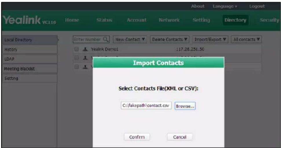
-
Click Confirm to import the local contact list.
The web user interface prompts "The original contact will be covered, continue?". -
Click Confirm to complete importing the local contact list.
The web user interface prompts "Contacts imported successfully!".
To import a CSV file of local contact lists via the web user interface:
- Click on Directory->Local Directory.
- Select Import from the pull-down list of Import/Export.
- Click Browse to locate a local contact list file (file format must be *.csv) from your local system.
4. Click Confirm.
The web user interface is shown as below:

5. (Optional.) Check the The first line as the title checkbox.
It will prevent importing the title of the local contact information which is located in the first line of the CSV file.
6. (Optional.) Check the Delete Old Contacts checkbox.
It will delete all existing local contacts while importing the contact list.
7. Select the desired value from the pull-down list.
- If Ignore is selected, this column will not be imported to the endpoint.
- If Display Name is selected, this column will be imported to the endpoint as the local contact's name.
- If number is selected, this column will be imported to the endpoint as the local contact's number.
- If Bandwidth is selected, this column will be imported to the endpoint as the contact's bandwidth.
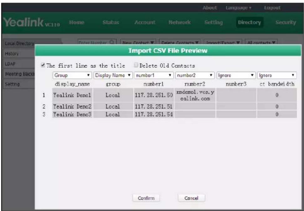
- Click Confirm to complete importing the local contact list.
The web user interface prompts "Contacts imported successfully!".
Note
The display name must be imported to the endpoint. If not, the CSV file cannot be imported.
To export a XML/CSV file of the local contact list via web user interface:
- Click on Directory->Local Directory.
- Select Export XML or Export CSV from the pull-down list of Import/Export.
The local contact list is saved to your local endpoint.
Call History Management
The VC110 video conferencing endpoint maintains call history lists of All Calls, Missed Calls, Placed Calls and Received Calls. The endpoint supports up to 100 history entries, including local history entries and Cloud history entries. You can view the call history, place a call or delete an entry from the call history list.
To save call history on the endpoint, you need to enable the history record feature in advance. The history record feature is enabled by default, and you can configure it via the remote control or web user interface.
To configure history record feature via the remote control:
-
Press (Menu soft key) to enter main menu.
-
Press ◀ or ▶ to select the Call Features menu.
- Press ▲or ▼to scroll to History record, and then press OK to enable or disable this feature.
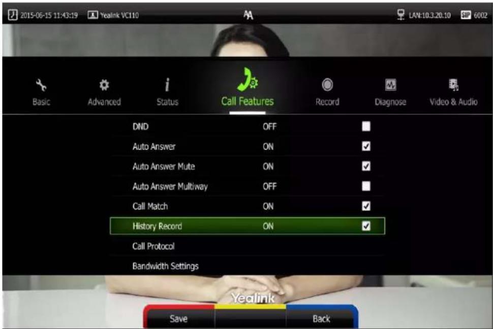
- Press (Save soft key) to accept the change.
The history record feature is configurable via the web user interface at the path Setting->Call Features->History Record.
Viewing Call History
You can view call history via the remote control, video conferencing phone or web user interface.
To view call history via the remote control:
- Press □ (Call soft key).
- Press ◀ or ▶ to select the History menu.
The display device shows recent call history.
- Press OK to expand the pull-down list of All Calls.
- Press ▲ or ▼ to select the desired call history list, and then press OK.
- Press ▲ or ▼ to view the desired call history.
If the call history is more than one page, you can press ⚠ or ⏱ to turn pages.
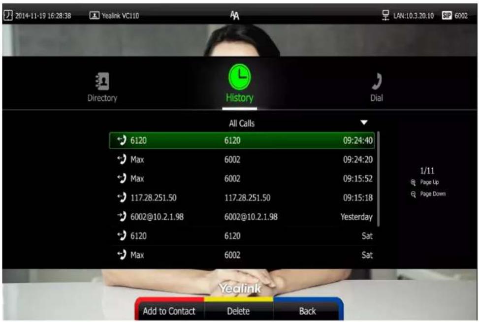
To view call history via the video conferencing phone:
- Press the History soft key.
The LCD screen of video conferencing phone displays all call records.

- Press ◀ or ▶ soft key to switch between All Calls, Missed Calls, Placed Calls, and Received Calls list.
- Press ▲ or ▼ to view the desired call history.
Call history can be viewed via the web user interface at the path Directory->History.
Placing a Call from the Call History List
You can place calls to contacts from the call history list via the remote control, video conferencing phone or web user interface.
To place a call from the call history list via the remote control:
-
Press □ (Call soft key).
-
Press ◀ or ▶ to select the History menu.
The display device shows recent call history.
- Select the desired call history list from the pull-down list of All Calls, and then press

- Press or to select the desired call history.
If the call history is more than one page, you can press + or - to turn pages.
- Press OK or
To place a call from the call history list via the video conferencing phone:
- Press the History soft key.
The LCD screen of video conferencing phone displays all call records.

-
Press ◀ or ▶ soft key to switch between All Calls, Missed Calls, Placed Calls, and Received Calls list.
-
Press 🙏 or 📋 to select the desired call history.
-
Press the Send soft key, ok or
Deleting an Entry from the Call History List
You can delete an entry from the call history list via the remote control or web user interface.
To delete an entry from the call history list via the remote control:
-
Press □ (Call soft key).
-
Press ◀ or ▶ to select the History menu.
The display device shows recent call history.
- Press ▲ or ▼ to select the desired call history.
If the call history is more than one page, you can press + or - to turn pages.
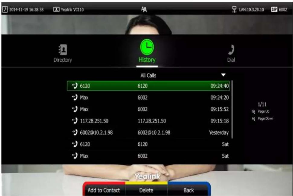
- Press □ (Delete soft key) to delete the entry.
To clear call history via the remote control:
-
Press □ (Call soft key).
-
Press ◀ or ▶ to select the History menu.
The display device shows recent history records.
- Press (Clear soft key) to clear all history records.
You can also select the call history list you want to clear from the pull-down list of All Calls, and then press (Clear soft key) to clear the selected list.
The display device prompt "Delete all records?".

-
Press ▲ or ▼ to select OK.
-
Press OK to clear the history records.
Adding a Local Contact from the Call History List
To add a local contact from the call history list via the remote control:
-
Press □ (Call soft key).
-
Press ◀ or ▶ to select the History menu.
The display device shows recent call history.
- Press ▲ or ▼ to select the desired call history.
If the call history is more than one page, you can press ✅ or 🔍 to turn pages.

-
Press (Add to Contact soft key).
-
Enter contact name in the Name field.
You can add more than one number for the local contact. For more information, refer to Adding Local Contacts on page 64.
- Press (Save soft key) to save the contact.
Call history management feature is configurable via the web user interface at the path Directory->History.
Call Protocol
The VC110 video conferencing endpoint supports SIP and H.323 call protocols. H.323 is commonly used to communicate to other video conferencing endpoints. SIP is commonly used to communicate with other VoIP devices. You can configure which protocol is to be used when the endpoint is making calls. When the Auto call protocol is used, the endpoint preferentially uses the H.323 protocol to place calls. If there is no available H.323 account on the endpoint, the endpoint will switch to the SIP protocol. You can also specify the desired protocol for the endpoint to place calls via the remote control or web user interface.
Note
Before configuring call protocol, ensure the remote endpoint supports the call protocol too. For more information, contact your system administrator.
To configure the call protocol via the remote control:
- Press (Menu soft key) to enter main menu.
- Press ◀ or ▶ to select the Call Features menu.
- Press ▲ or ▼ to scroll to Call Protocol, and then press (ok).
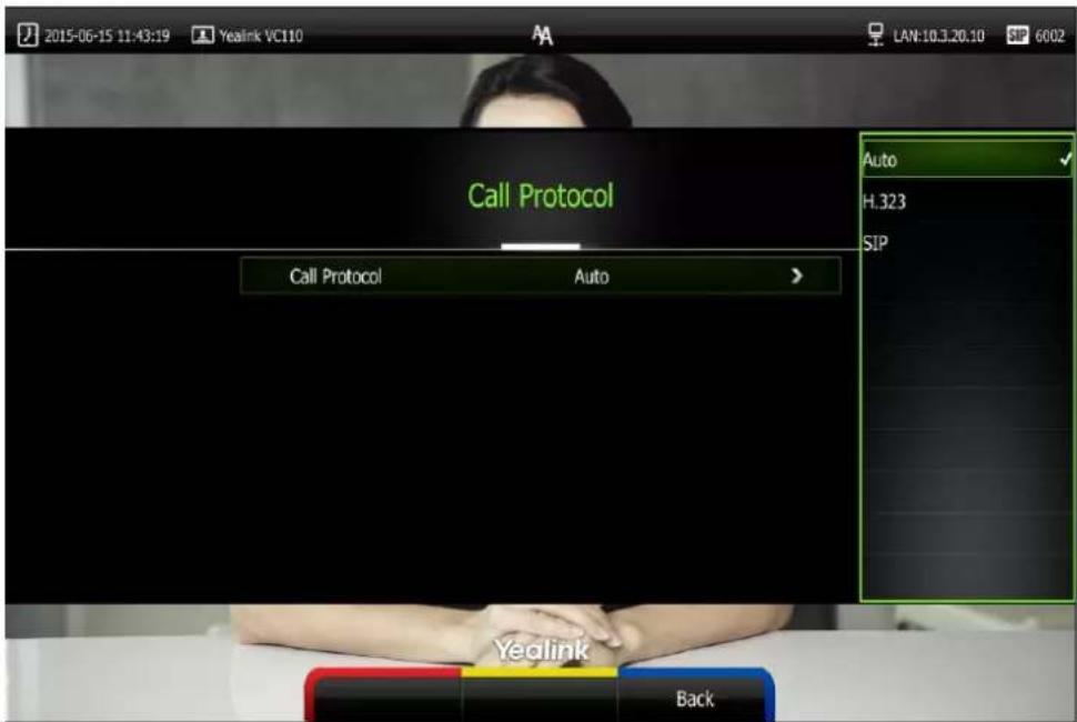
- Select desired protocol or Auto from the pull-down list of Call Protocol.
- Press (Save soft key) to accept the change.
Call protocol is configurable via the web user interface at the path Setting->Call Features->Call Protocol.
Bandwidth Settings
By default, the endpoint automatically detects the available bandwidth and uses it to connect other endpoints. The VC110 supports connecting to other devices with different bandwidth. If a device with lower bandwidth joins a call, the video quality will stay the same or will not reduce a lot.
You can specify the uplink and downlink bandwidths for the endpoint to achieve the best result. The uplink bandwidth refers to the max bandwidth of outgoing calls. The downlink bandwidth refers to the max bandwidth of incoming calls.
Available bandwidths for the endpoint are: Auto, 256kb/s, 384kb/s, 512 kb/s, 640 kb/s, 768 kb/s, 1024kb/s, 1280kb/s, 1500kb/s, 2000kb/s, 3000kb/s, 4000kb/s.
You can configure the uplink and downlink bandwidth of the endpoint via the remote control or web user interface.
Note
The actual bandwidth depends on the performance of the remote endpoint, and is affected by the quality of the communication channel.
To configure the uplink and downlink bandwidth via the remote control:
-
Press (Menu soft key) to enter main menu.
-
Press ◀ or ▶ to select the Call Features menu.
-
Press ▲ or ▼ to scroll to Bandwidth Settings, and then press OK.
-
Select desired bandwidth from the pull-down list of Uplink Bandwidth.
If Auto is selected, the endpoint will negotiate the appropriate bandwidth automatically.
- Select desired bandwidth from the pull-down list of Downlink Bandwidth.
If Auto is selected, the endpoint will negotiate the appropriate bandwidth automatically.

- Press (Save soft key) to accept the change.
Note
The priority of bandwidth is as follows:
Endpoint bandwidth> Contact bandwidth (refer to Adding Local Contacts).
For example: the endpoint bandwidth is 512kbps, if contact bandwidth is set to a value greater than 512bps, then the actual contact bandwidth will be 512bps. If contact bandwidth is set to a value less than 512bps, then the actual contact bandwidth will be the value set by user.
Bandwidth is configurable via the web user interface at the path Setting->Call
Features->Uplink Bandwidth/Downlink Bandwidth.
Audio Settings
Audio Output Device
The endpoint supports the following audio output devices:
• Auto (audio output device with the highest priority is selected automatically)
• VCS Phone (video conferencing phone)
• HDMI (built-in speakerphone of the display device)
• Line Output (speakerphone connected to the Line Out port on the VC110 all-in-one unit)
By default, the endpoint automatically selects the audio output devices with the highest priority. The priority is: VCS Phone> HDMI>Line Output. If the audio output device with the highest priority is removed from the VC110, the VC110 will select the next highest priority device.
![graph TD A["VC110"] --> B["Auto"] A --> C["VCS Phone"] A --> D["HDMI"] A --> E["Line Output"] B --> F["The priority order is from top to bottom."] C --> F D --> F E --> F](/content/2026/05/921811/images/640302d069d011b42618a93c5b8dc498484a1503d66a0207f80e4ead54a76d57.jpg)
You can also specify the desired audio output device via the remote control or the web user interface.
To configure the audio output device via the remote control:
- Press (Menu soft key) to enter main menu.
- Press ◀ or ▶ to select the Video & Audio menu.
- Press ▲ or ▼ to scroll to Audio Settings, and then press OK.
- Select desired audio output device from the pull-down list of Audio Output.
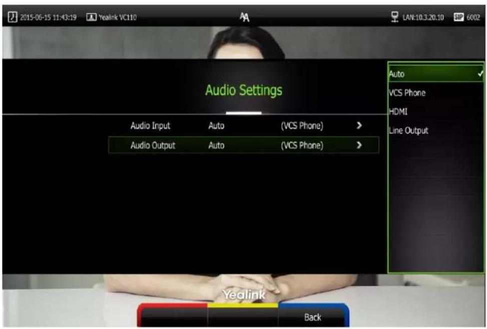
- Press (Save soft key) to accept the change.
Audio output device is configurable via the web user interface at the path Setting->Video & Audio->Audio Output.
Audio Input Device
The endpoint supports the following audio input devices:
• Auto (select the audio input device with the highest priority)
• VCS Phone (video conferencing phone)
• Wired Micpod (VCM30)
• Wireless Micpod (VCM60)
• Built-in Micphone (built-in microphone of VC110)
• Line Input (microphone connected to the Line In port on the VC110 all-in-one unit)
• Line In + VCS Phone
• Line In + Wired Micpod
• Line In + Wireless Micpod
The priority of audio input device is:
![graph TD A["VC110"] --> B["Auto"] A --> C["VCS Phone (Line In + VCS Phone)"] A --> D["Wired Micpod (Line In + Wired Micpod)"] A --> E["Wireless Micpod (Line In + Wireless Micpod)"] A --> F["Built-in Micphone"] A --> G["Line Input"] H["The priority order is from top to bottom."] --> I](/content/2026/05/921811/images/c9c50eb443873a33d3e09b80086bc36b81c3c48c10161fabb2d68a0bb412921a.jpg)
By default, the VC110 automatically selects the audio input devices with the highest priority. If you select "Line In + device" option, the VC110 will use microphone connected to the Line In port and the corresponding device to pick up audio at the same time.
You can also specify the desired audio input device via the remote control or the web user interface.
To configure the audio input device via the remote control:
- Press (Menu soft key) to enter main menu.
- Press ◀ or ▶ to select the Video & Audio menu.
- Press ▲ or ▼ to scroll to Audio Setting, and then press OK.
-
Select desired audio input device from the pull-down list of Audio Input.
-
If VCS Phone is selected as the audio output device manually or automatically, the audio input device must be VCS Phone or Line Input +VCS Phone.
- If Line Input is selected as the audio input device, the near-end audio output device will not play sound from the Line Input device.
- If "Line In + device" is selected as the audio input device, the near-end audio output device will play sound from the Line Input device.
During a video training for main office and branch office, both offices need to hear the video sound, you can select this option.
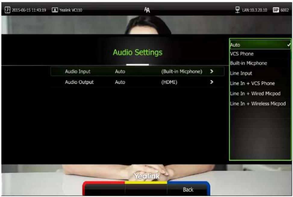
- Press (Save soft key) to accept the change.
Audio input device is configurable via the web user interface at the path Setting->Video & Audio->Audio Input.
Far-end Camera Control
Local video is displayed on the display device of the far site during a call. For the best view, you can enable the Far Control of Camera feature to allow the far site to control the focus and angle of the local camera. You can also specify whether the far site is allowed to store and use the local camera presets.
You can configure the far-end camera control feature via the remote control or web user interface.
Far-end camera control features you need to know:
| Parameters | Description |
| Far Control of Camera | Allows the far-end to control the local camera. |
| Far Set of Camera Presets | Allows the far-end to create presets for the local camera |
| Far Move to Camera Presets | Allows the far-end to point local camera at pre-defined locations. |
To configure Far-end Camera Control via the remote control:
-
Press (Menu soft key) to enter main menu.
-
Press ◀ or ▶ to select the Video & Audio menu.
-
Press ▲ or ▼ to scroll to Far-end Camera Control, and then press (OK).
-
Press ▲ or ▼ to scroll to Far Control of Camera, and then press OK to enable or disable this feature.
-
Press ▲ or ▼ to scroll to Far Set of Camera Presets, and then press OK to enable or disable this feature.
-
Press ▲ or ▼ to scroll to Far Move to Near Camera Presets, and then press OK to enable or disable this feature.
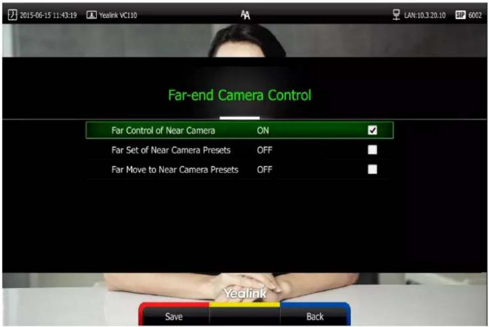
- Press (Save soft key) to accept the change.
Far-end Camera Control is configurable via the web user interface at the path Setting->Video & Audio->Far Control Near Camera/Far Set of Camera Presets/Far Move to Camera Presets
Controlling Far-end Camera
To control far-end camera via the remote control during a video call:
- Press (More soft key) during an active call.
- Press ▲ or ▼ to scroll to Near/Far Camera, and then press OK.
- Select the remote video, and then press OK.
- Press the navigation key to adjust the angle of the camera.
- Long press 🔒 or ⊕ to adjust the focus of the camera.
Note
If you want to configure presets for the far-end, refer to Configuring Camera Presets on page 103.
Using the VC110 Video Conferencing Endpoint
The VC110 video conferencing endpoint can be used to place calls, answer calls, or conduct a conference call. You can change layout, record videos or capture screenshots during a call.
This chapter provides basic operating instructions for the VC110 video conferencing endpoint.
Topics include:
- Placing Calls
- Answering or Rejecting Calls
- Call Management
- Ending Calls
If you require additional information or assistance with your new phone, contact your system administrator.
Account Polling
When you dial account numbers of other endpoint, account polling feature enables your endpoint to use different call types according to this priority: Cloud platform>H.323
account>SIP account. If you cannot call other endpoints using all your registered accounts, then this call fails.
Account polling is disabled by default. When you register multiple accounts (2 or more) for your endpoint, you can enable account polling feature. You can configure account polling feature via web user interface only.
To configure account polling via web user interface:
- Click on Setting->Call Features.
- Select the desired value from the pull-down list of Account Polling.
- If you select Disabled, the endpoint can only call other endpoints using the call type with the highest priority.
- If you select Enabled, the endpoint will attempt to call other endpoint using different call types according the priority.

- Click Confirm to accept the change.
The following example shows the way calls are placed when account polling is enabled or disabled.
Scenario:
-
Endpoint A is registered with a Yealink Cloud account and a SIP account.
-
On endpoint A, select Auto from the pull-down list of Call Type before calling.

- On endpoint A, dial the account numbers of endpoint B.
Result:
- If account polling is disabled, endpoint A can only use its Cloud account (highest priority) to call endpoint B.
- If account polling is enabled, endpoint A will use its Cloud account (highest priority) to call endpoint B first. If this call fails, endpoint A continues to use its SIP account (next priority) to call endpoint B.
Placing Calls
You can place a call in three ways using your VC110 video conferencing endpoint:
• Using the remote control
• Using the video conferencing phone
• Via the web user interface
The VC110 video conferencing endpoint supports two call modes:
- Voice Call
- Video Call
Note
The endpoint supports placing calls using contact numbers, SIP URI, IP address, H. 323 account or extension. SIP URI and IP addresses can be up to 32 characters. For example: SIP URI:2210@sip.com, IP: 192.168.1.15.
For more information, contact your system administrator.
You can search and dial a contact from the call history or local directory. For more information, refer to Directory on page 63 and Call History Management on page 73.
If the endpoint fails to call, you can troubleshoot the problems according to the following prompts:
| Prompts | Description |
| Call Failed Busy Here | Remote endpoint rejects your SIP call.Remote endpoint does not answer your SIP call.Remote endpoint has reached maximum sessions when you place a SIP call. |
| Call Failed Remote endpoint refused call | Remote endpoint rejects your H.323 callRemote endpoint does not answer your H.323 call.Remote endpoint has reached maximum sessions when you place an H.323 call. |
| Network disconnected | Local network is disconnected. |
| Call Failed Request Time Out | Remote endpoint network anomalyRemote endpoint is powered off. |
| Maximum number of sessions reached | Local endpoint has reached maximum sessions. |
During a video call, the call duration and video of remote endpoint are displayed on the display device.
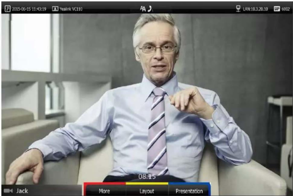
Placing a Call Using the Remote Control
To place a call using the remote control:
- Press □(Call soft key), ▼ or any numeric key to enter the dialing screen.
- Select the desired account type from the pull-down list of Call Type before calling.
If you select Auto, the endpoint will select the desired account type according to the priority.
If you dial an account, the priority is: Cloud platform>H.323 account>SIP account. For more information, refer to on page.
If you dial an IP address, the priority is: H.323 IP Call>SIP IP Call.
- Enter the desired number using the keypad or the on-screen keyboard.
You can also select the desired record from the recent call history.
- Press (Voice/Video soft key) to switch call mode.

- Press ok or
Placing a Call Using the Video Conferencing Phone
To place a call using the video conferencing phone:
- Enter the desired number using the keypad.
- Press OK, or the Send soft key.
Placing a Call via Web User Interface
To place a call via web user interface:
-
Click Home.
-
Enter the desired number in the Enter Number field.
-
(Optional.) Select the desired account type.
If you select Auto, the endpoint will select the desired account type according to the priority.
If you dial an account, the priority is: Cloud platform>H.323 account>SIP account. For more information, refer to on page.
If you dial an IP address, the priority is: H.323 IP Call>SIP IP Call.
- (Optional.) Select the desired bandwidth from the pull-down list of Auto.
If you select Auto, the endpoint will select the appropriate bandwidth automatically.
- Click Video Call or Voice Call.

Placing Multiple Calls
The VC110 video conferencing endpoint supports one video call and one voice call. You can use the remote control, video conferencing phone or web user interface to place multiple calls.
To place a multiple call via the remote control:
-
Place a call to the first party.
-
When the first party answers the call, press (More soft key) to open More screen.
-
Press ▲ or ▼ to scroll to Dial, and then press OK to place a new call.
-
Enter the number of the second party, and then press OK or ☑.
When the second party answers the call, you have created a three-way conference.
By default, the first call is video call, and the second call is voice call.
Note
You can press 🙏 or 🕒 to enter the pre-dialing screen during a call.
When you try to invite a new party during the third-way conference, the endpoint will prompt "Maximum number of sessions reached".
New incoming call will be rejected automatically during a third-way conference, and the number of missed calls will be displayed on the display device.
To place a multiple call via the video conferencing phone:
- Enter the desired number using the keypad.
- When the first party answers the call, press Dial soft key to place a new call.
- Enter the number of the second party, and then press OK, or the Send soft key. When the second party answers the call, you have created a three-way conference.
To place a multiple call via the web user interface:
- Click Home.
- Enter the desired number in the Enter Number field.
- (Optional.) Select the desired account type.
If you select Auto, the endpoint will select the desired account type according to the priority.
If you dial an account, the priority is: Cloud platform>H.323 account>SIP account. For more information, refer to on page.
If you dial an IP address, the priority is: H.323 IP Call>SIP IP Call.
- (Optional.) Select the desired bandwidth from the pull-down list of Auto.
If you select Auto, the endpoint will select the appropriate bandwidth automatically.
- Click Video Call or Voice Call.
When the first party answers the call, the call is established.

- Repeat the steps 3 to 6 to invite another party to join the conference.
Note
The endpoint supports one video call and one voice call, or two voice calls.
If you click Video Call twice to place multiple calls. The first call will be a video call and the second call will be a voice call by default.
Answering or Rejecting Calls
When the endpoint receives a call, you can answer or reject the call in the following ways:
• Using the remote control
• Using the video conferencing phone
If the endpoint accepts multiple calls, a conference call will be established.
To answer a call:
Do one of the following:
- Press OK or 📋 on the remote control.
- Press OK, or the Answer soft key on the video conferencing phone.
To reject a call:
Do one of the following:
- Press 📋 or select Reject first, and then press OK on the remote control.
- Press 📊 or the Reject soft key on the video conferencing phone.
Auto Answer
You can enable the auto answer feature for the endpoint to automatically answer the incoming call.
Auto answer features you need to know:
| Parameters | Description |
| Auto Answer | Enables or disables the endpoint to automatically answer the incoming call. |
| Auto Answer Mute | Enables or disables the endpoint to turn off the microphone when an incoming call is answered automatically. The auto answer mute feature can be enabled only when the auto answer feature is enabled. |
| Auto Answer Multiway | Enables or disables the endpoint to answer a new incoming call automatically during an active call. The auto answer multiway feature is available only when the auto answer is enabled. |
Auto answer is configurable via the remote control or web user interface.
To configure auto answer via the remote control:
-
Press (Menu soft key) to enter main menu.
-
Press ◀ or ▶ to select the Call Features menu.
-
Press ▲ or ▼ to scroll to Auto Answer, and then press OK to enable or disable this feature.
-
Press ▲ or ▼ to scroll to Auto Answer Mute, and then press OK to enable or disable this feature.
If you disable the auto answer feature, the endpoint will disable the auto answer mute feature automatically.
- Press ▲ or ▼ to scroll to Auto Answer Multiway, and then press OK to enable or disable this feature.

- Press (Save soft key) to accept the change.
If the auto answer feature is enabled, the AA icon will appear on the status bar of the display device. The AA icon will appear on the LCD screen of the video conferencing phone.
Auto answer is configurable via the web user interface at the path Setting->Call
Features->Auto Answer/Auto Answer Mute/Auto Answer Multiway.
Do Not Disturb (DND)
You can use DND to reject incoming calls automatically on the endpoint. Callers will receive a busy message.
You can enable/disable DND for the endpoint via the remote control, video conferencing phone or web user interface. You can also enable DND for the endpoint to reject incoming call automatically during an active call.
To enable the DND mode via the remote control:
-
Press (Menu soft key) to enter main menu.
-
Press ◀ or ▶ to select the Call Features menu.
-
Press ▲ or ▼ to scroll to DND, and then press OK to enable this feature.

- Press (Save soft key) to accept the change.
The icon will appear on the status bar of display device, and "DND ON!" will be prompted at intervals. The DND icon will appear on the LCD screen of the video conferencing phone.
The endpoint will reject all incoming calls automatically, and the icon and numbers of missed calls are displayed on the status bar of the display device. If the endpoint places a call, after the call is established, the DND mode will be disabled automatically.
When video conferencing phone is idle, you can also press the DND soft key to enable or disable this feature.
DND is configurable via the web user interface at the path Setting->Call Features->DND.
DND during an active call
You can use the DND mode to reject incoming calls automatically during an active call.
You can enable/disable the DND mode for the endpoint via the remote control, video conferencing phone or web user interface. The DND mode will be disabled after the call ends.
To enable the DND mode during a video call via the remote control:
-
Press (More soft key) during a video call.
-
Press ▲ or ▼ to scroll to DND, and then press OK to enable this feature.
The - icon will appear on the status bar of display device, the DND icon will appear on the LCD screen of the video conferencing phone.
- Press (Back soft key) to return.
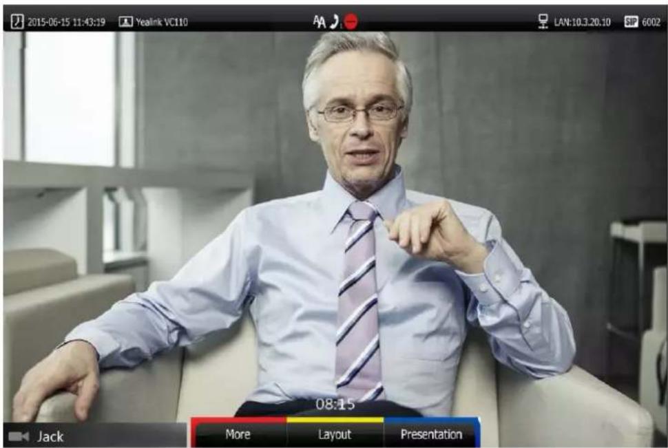
To enable the DND mode during a voice call via the remote control:
- Press (DND) during a voice call.
The -icon will appear on the status bar of display device, the DND icon will appear on the LCD screen of the video conferencing phone.
You can also press the DND soft key on the video conferencing phone to enable or disable the DND feature during a voice call.
DND during an active call feature is configurable via the web user interface at the path Home->DND.
Ending Calls
During a two-way call, do one of the following to end the call.
- Press 📞 on the remote control.
- Press 📋 or the End Call soft key on the video conferencing phone.
- Click Hang Up All button on the web user interface.
The interface prompts "Hang up?"
Click Confirm to end the call.
During a multi-way call, do one of the following to end the call.
- Press 📞 on the remote control.
The display device prompts" End All Active Calls?"
Select Yes, and then press OK.
- Press 📋 or the End Call soft key on the video conferencing phone.
The LCD screen of the video conferencing phone prompts "End All Active Calls?"
Press OK or the Yes soft key to end all calls.
- Click Hang Up All button on the web user interface.
The interface prompts "Hang up?"
Click Confirm to end the call.
During a multi-way call, you can remove any party via the remote control or web user interface.
To remove any party via the remote control:
- Press (More soft key) during a multi-way call.
- Press ▲ or ▼ to scroll to Remove, and then press OK.

- Select the party you want to remove, and then press (ok).
- Press (Remove soft key).
To remove any party from a multi-way call via the web user interface, go to the path Home (Hover your cursor over the number of the remote endpoint, and then click 📄).
Call Management
You can enable mute mode, record video, control the video and change video layout during an active call.
Call Mute
You can enable mute mode to mute the microphone of the active audio device during an active
call, and then the other party cannot hear you.
To mute a call:
Do one of the following:
- Press on the remote control.
- If VCM60 works as the audio input device of the VC110 video conferencing endpoint.
You can tap 📋 to mute the call. The mute indicator LED will illuminate solid red.
- If VCM30 is connected to the Audio In port of cable hub.
You can tap 📁 to mute the call. The mute indicator LED will illuminate solid red.
- If video conferencing phone is connected to the Audio In port of cable hub.
You can press 📄 to mute the call. The LED indicators on the video conferencing phone will illuminate solid red. And the LCD screen on the video conferencing phone is shown as below:
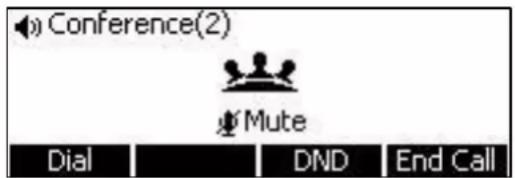
- Log into the web user interface, check the Mute checkbox.
If video conferencing endpoint is muted, the icon will appear on the local video.
Call Statistics
If voice quality is poor during a call, you can enter the Call Statistics screen to view the current status of the call to find out why.
Codec, bandwidth, total packet lost and other parameters about presentation are included in the call statistics. For example, when a delay occurs or the video has a 'mosaic' look, you can view the total packet loss to check whether the packet has been lost.
Call statistics is configurable via the remote control or web user interface.
To view call statistics via the remote control:
-
Press (More soft key) during an active call.
-
Press ▲ or ▼ to scroll to Call Statistics, and then press OK to enter the Call Statistics screen.
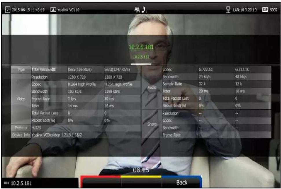
-
During multi-way call, press ◀ or ▶ to see call statistic for every participant.
-
Press (Back soft key) to return.
To view call statistics via the web user interface, go to the path Home (Hover your cursor over the other party on the left side of the screen, and then click ⓘ).
- During multi-way call, press ◀ or ▶ to see call statistic for every participant.
Changing the Video Input Source
VC110 video conferencing endpoint supports two video input sources: camera and PC.
When the PC is connected to the cable hub, the display device shows the presentation from the connected PC. If two display devices are connected to the VC110 all-in-one unit, the video image from the camera is shown on the primary display device, and the presentation from the PC is shown on the secondary display device.
During a call, the display device will display differently depending on whether it has connected to a secondary display device or the selected video input source.
You can change the video input source via the remote control and web user interface.
To change video input when the endpoint is idle via the remote control:
- Press

The display device shows Camera and PC input sources.
- Press ◀ or ▶ to select the desired input source, and then press OK.
The display device shows the selected source.
To change video input during a call:
1. Press

The display device shows Camera, Camera and PC and PC input sources.
- If you select PC, the remote video image is shown in full screen.
- If you select Camera and PC or PC, the PC presentation is shown in big size, and other video images along the right side of the screen are shown in small size.
- If you select Camera, the remote video image is shown in full screen.
2. Press ◀or ▶ to select the desired input source, and then press OK.
The display device shows the selected source.
Video input is configurable via web user interface at the path Home->Input.
Presentation
The endpoint supports sharing video and documents on a PC while simultaneously displaying the main video. We recommend using a dual display configuration for sharing contents. During a call, if a PC is connected to the cable hub, the endpoint will start a presentation automatically. Both local and remote display devices will share contents.
You can also start/end a presentation during a call via the remote control or video conferencing phone (ensure a PC is connected to the cable hub). If you disconnect the PC, the presentation will end automatically.
Only one presentation can be shared at a time. A presentation started later will replace the previous presentation.
o start/stop presentation manually during a call:
Do one of the following:
- Press (Presentation soft key) on the remote control to start or stop a presentation.

- Press 📄 on the VCP40 phone to start or stop a presentation.
Configuring Camera Presets
You can store the preset to a numeric key via the remote control or web user interface. Each camera preset stores the camera pan, tilt, and zoom settings. This means that you can point a camera at pre-defined locations by pressing stored keys.
You can store up to 10 preset camera positions using the remote control. If you want to store more than 10 preset camera positions, you can enable the multiple preset feature. For more information, refer to Yealink VC110 All-in-one HD Video Conferencing Endpoint Administrator Guide.
Storing a Local Camera Preset
To store a local camera preset when the endpoint is idle:
-
Press (Preset soft key).
-
Press the navigation key to adjust the angle of the camera or press ⚠ or ⏱ to adjust the focus of the camera.
-
Long press any number key (0-9) on the remote control until the screen prompts "Preset Key 'X' successfully saved" ("X" stands for the saved key).
Current camera position and focus are stored to the numeric key.
- Press (Exit soft key) to return to the idle screen.
To store a local camera preset during a call:
-
Press (More soft key) during an active call.
-
Press ▲ or ▼ to scroll to Camera Preset, and then press OK.
-
Press the navigation key to adjust the angle of the camera or press ⚠ or ⏰ to adjust the focus of the camera.
-
Long press any number key (0-9) on the remote control until the screen prompts "Preset Key 'X' successfully saved" ("X" stands for the saved key).
Current camera position and focus are stored to the numeric key.
- Press (Exit soft key) to return to the idle screen.
Moving Local Camera to a Preset Position
To move the local camera to a preset position when the endpoint is idle:
-
Press (Preset soft key).
-
Press the numeric key that is already associated with a preset.
The local camera will adjust to the preset.
- Press (Exit soft key) to return to the idle screen.
To move the local camera to a preset position during a call:
-
Press (More soft key) during an active call.
-
Press ▲ or ▼ to scroll to Camera Preset, and then press OK.
-
Press the numeric key that is already associated with a preset.
The local camera will adjust to the preset.
- Press (Exit soft key) to return to the idle screen.
To move local camera to a preset position via web user interface, go to the path Home (Hover your cursor over your number, and then click 📷 and click a numeric key that is already associated with a preset).
Storing a Far-end Camera Preset
If the far-end camera enables the far-end camera control feature (For more information, refer to Far-end Camera Control on page 85) and corresponding camera control protocol is enabled (For more information, refer to your system administrator), you can configure camera preset for the far-end camera during the video call.
To store a far-end camera preset during a call:
-
Press (More soft key) during an active call.
-
Press ▲ or ▼ to scroll to Near/Far Camera, and then press OK.
-
Select the remote video, and then press OK.
-
Press the navigation key to adjust the angle of the far-end camera or press + or - to adjust the focus of the far-end camera.
-
Press (More soft key).
-
Press ▲ or ▼ to scroll to Camera Preset, and then press OK.
-
Long press any number key (0-9) on the remote control, far-end camera position and focus are stored to the numeric key.
-
Press (Exit soft key).
Moving Far-end Camera to a Preset Position
To move the far-end camera to a preset position during a call:
-
Press (More soft key) during an active call.
-
Press ▲ or ▼ to scroll to Near/Far Camera, and then press OK.
-
Select the remote video, and then press OK.
-
Press (More soft key).
-
Press ▲ or ▼ to scroll to Camera Preset, and then press OK.
-
Press the numeric key that is already associated with a preset. The far-end camera will adjust to the preset.
-
Press (Exit soft key).
Clearing the Local Camera Presets
To clear the stored local camera presets via remote control:
-
Press (Menu soft key) to enter main menu.
-
Press ◀ or ▶ to select the Video & Audio menu.
-
Press ▲ or ▼ to scroll to Camera General Settings, and then press OK.
-
Press ▲ or ▼ to scroll to Clear Preset Position, and then press OK.
-
Select Ok, and then press OK to delete all presets.
Video Recording
When the endpoint is idle, you can record local video via the remote control. During a call, the video and presentation which are shown on the display device can be recorded via the remote control and video conferencing phone.
Before recording video, you need to insert a USB flash drive to the USB port on the VC110 all-in-one unit to store recorded video and make sure the USB feature is enabled. For more information, please refer to USB Configuration on page 62. The recorded video will be saved in .mkv format and named as the recorded time and date. Video can be played on either the endpoint itself or on a computer using an application capable of playing .wav files.
Note
The endpoint supports FAT32 and NTFS format USB flash drive or removable hard drive. When using the NTFS format, only the first partition is supported.
After the USB flash drive is inserted to the USB port on the VC110 all-in-one unit and the USB feature is enabled, the display device will prompt "USB device available now".
The icon will appear on the status bar of the display device, and the USB icon will appear on the LCD screen of the VCP40 phone.
Before recording video, you need to know the following:
- When recording video, it is not allowed to play or delete the video from the menu.
- When recording video, it is not allowed to capture screenshots, but you can view and delete screenshots.
- When playing video recording, it is not allowed to record again. But when the video is paused, you can press *,告 to record again.
- When receiving or making a call, it is not allowed to record.
- When there is an incoming call during recording, the endpoint will quit recording.
- When recording during a video call, the record will be finished automatically after the call ends.
- When playing or recording video, it is unavailable to press 🤒 to return to the idle screen.
- When playing, recording or pausing video, the endpoint will not go to sleep automatically.
- If you remove the working USB flash drive or insert another USB flash drive during recording, the recording will be stopped.
To configure video recording via web user interface:
- Click on Setting->Video & Audio.
2. Select the Enabled from the pull-down list of Recording.
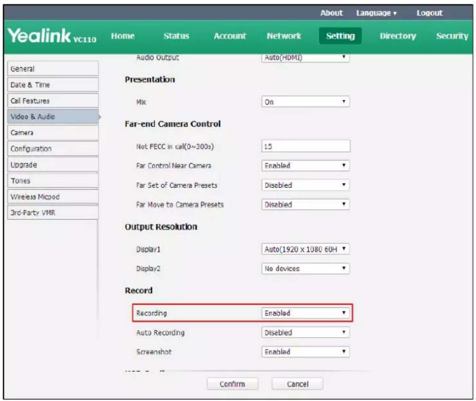
3. Click Confirm to accept the change.
To record video when the endpoint is idle via the remote control:
- Press *.B to start recording and press *.B again to stop recording.
To record video during a call via the remote control:
-
Do one of the following:
-
Long press *.to start recording and long press *. again to stop recording.
- Press (More soft key) to open More screen.
Press ▲ or ▼ to scroll to USB Recording, and then press OK to start recording.
Open the More screen, scroll to USB Recording again, and then press ok to stop recording.
To record video during a call via the video conferencing phone:
- Press the Start REC soft key to start recording and press the Stop REC soft key again to stop recording.
When you start recording, the display device will show 🙏 and the recording time. When you stop recording, the recording icon disappears from the screen. The display device prompts "Successfully video recording!"
Note
If you start recording during a call, both your display device and remote display devices will show the icon on your video image.
To view recorded video via the remote control:
Insert the USB flash drive with the recorded video to the VC110 all-in-one unit.
-
Press (Menu soft key) to enter main menu.
-
Press ◀ or ▶ to select the Record menu.
-
Press ▲ or ▼ to scroll to Videos, and then press OK.
-
Press ▲ or ▼ to select the desired Video.
-
Press OK or (Play soft key).
You can do the following:
- To pause the video, press ☐ (Pause soft key). The ☐ (Play soft key) appears on the LCD TV screen.
Press □ (Play soft key) to continue playing video.
- To skip forward the video, press ▶. Press once to skip forward 8 seconds.
- To rewind the video, press ◀. Press once to rewind 8 seconds.
- To adjust the volume of the speakerphone, press 📄 - or 📄 + .
- To stop the video, press (Stop soft key).
When receiving an incoming call while you are playing video, the endpoint will stop playing video automatically.
To delete recorded video via the remote control:
-
Press (Menu soft key) to enter main menu.
-
Press ◀ or ▶ to select the Record menu.
-
Press ▲ or ▼ to scroll to Videos, and then press OK.
-
Press ▲ or ▼ to select the desired video.
-
Press (Delete soft key).
The display device prompts "Delete this video?"

- Select OK, and then press OK to delete the video.
Auto Recording
Auto recording feature is available only when the recording feature is enabled. If it is enabled, the endpoint will start recording automatically once a call is established. Make sure a USB flash drive has been inserted to the USB port on the VC110 all-in-one unit and the USB feature is enabled. You can configure auto recording feature via web user interface only.
To configure auto recording feature via web user interface:
- Click on Setting->Video & Audio.
2. Select the desired value from the pull-down list of Auto Recording.

3. Click Confirm to accept the change.
Screenshot
You can capture the screenshot from the camera via the remote control or web user interface. You need to insert a USB flash drive to the USB port on the VC110 all-in-one unit to store screenshots when you are using remote control and make sure the USB feature is enabled. For more information, please refer to USB Configuration on page 62.
You can view, delete or scale the screenshots via the remote control.
When you capture a screenshot via the web user interface, you can save the screenshots to the computer. The stored screenshot will be saved in .jpg format and named as the captured time and date. You can view the screenshot using an application capable of viewing .jpg pictures.
Note
The endpoint supports FAT32 and NTFS format USB flash drive or removable hard drive. When using the NTFS format, only the first partition is supported.
After the USB flash drive is inserted to the USB port on the VC110 all-in-one unit and the USB feature is enabled, the display device will prompt "USB device available now".
The icon will appear on the status bar of the display device, and the USB icon will appear on the LCD screen of the VCP40 phone.
Before capturing screenshots, you need to know the following:
- When receiving or making a call, it is not allowed to capture screenshots.
- When recording video, it is not allowed to capture screenshots.
- If two USB flash drives are connected, and you remove the working USB flash drive, the remained one can continue to work seamlessly.
To capture screenshots when the endpoint is idle via the remote control:
- Press #
To capture screenshots during a call via the remote control:
-
Do one of the following:
-
Long press #
- Press (Menu soft key) to open More screen.
Press ▲ or ▼ to scroll to Screenshot, and then press OK to capture screenshots.
The icon at the status bar of the display device shows "+1" animated effects.
To view screenshots via the remote control:
- Press (Menu soft key) to enter main menu.
- Press ◀ or ▶ to select the Record menu.
- Press ▲ or ▼ to scroll to Screenshots, and then press OK.
- Press ▲ or ▼ to select desired screenshots.
- Press OK or View soft key).
You can do one of the following:
- Press ◀ or ▶ to view previous or next screenshot.
- Press + or - to zoom screenshot in/out.
- Press (Original size soft key) to view the original size of the screenshot.
To delete screenshots via the remote control:
- Press (Menu soft key) to enter main menu.
- Press ◀ or ▶ to select the Record menu.
- Press ▲ or ▼ to scroll to Screenshots, and then press OK.
- Press ▲ or ▼ to select desired screenshots.
- Press (Delete soft key).
The display device prompts "Delete this screenshot?"
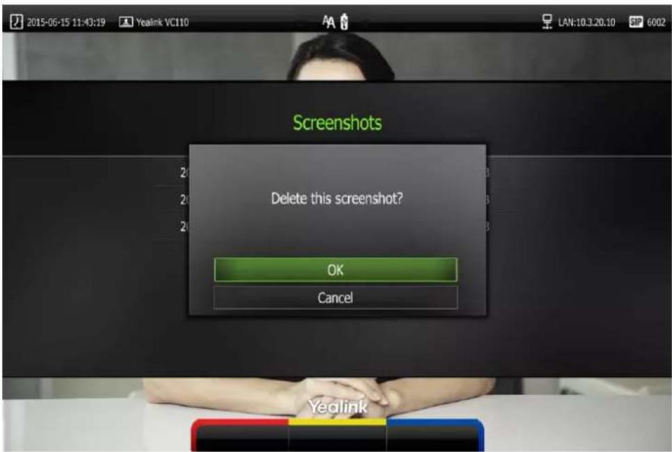
- Select OK, and then press OK to delete the screenshot.
Screenshot is configurable via the web user interface at the path Setting->Video & Audio->Screenshot.
Capture the screenshot via the web user interface at the path Home->Screenshot.
Video Layout
The total number of available screen layouts depends on the number of connected callers, whether a single display or a dual display is used, and whether a presentation is being viewed.
Screen layouts appear as one of the following types:
- One big, other small ☐): The selected video image is shown in a big size, the other video images along the right side of the screen are shown in small sizes.
• Full screen ): The selected video image is shown in full size.
• Same size (☐): All video images are shown in the same size.
Changing Video Layout
To change screen layout via the remote control:
- Press □ (Layout soft key) during an active call.
- Press ◀ or ▶ to select a video.
- Press the desired layout soft key.
The selected video will be shown in the selected layout.
For example, if you select 📊 during a two-way calls, the video layout will be shown as
below.
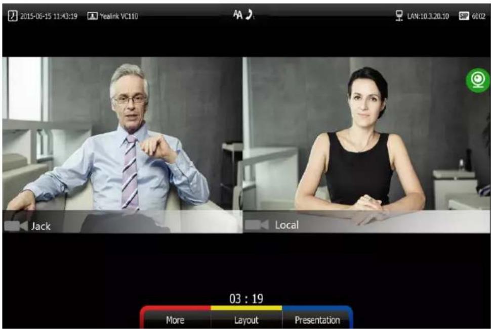
Single Display Screen Layouts
Two-way Video Calls
The far-end video image is shown in full size by default.
Two-way Video Call with Presentation
Presentation is shown in a big size. The other video images along the right side of the screen are shown in small sizes.
![graph TD A["PC presentation"] --> B["Far end"] A --> C["Local"]](/content/2026/05/921811/images/a1889ca07eac2df8896d82ae1c53ab297b33b68ea13f8240e9eccaa71781e3d4.jpg)
Dual Display Screen Layouts
The VC110 has two display ports. When connecting only one display device to the VC110 all-in-one unit, Display1 port is the only available port. To make it easier for users to view video images, users can connect two display devices to Display1 and Display2 ports respectively. When two display devices are connected to the VC110 all-in-one unit, the status bar of the primary display device will display icon.
Two-way Video Calls
In the primary display device, the remote video image is shown in full size. In the secondary display device, the local video image is shown in full size.

Primary display device
Secondary display device
Two-way Video Call with Presentation
In the primary display device, the remote video image is shown in big size, and the local video image along the right side of the screen is shown in small size.
In the secondary display device, the presentation is shown in full size.

Primary display device
Secondary display device
Specifying the Content on the Second Screen
To specify the content to be displayed on the secondary display device via the remote control:
- Press (More soft key) during an active call.
- Select Focus (Display2), and then press OK.
- Press ◀ or ▶ to select the desired content, and then press OK.
The secondary display device displays the selected content. The icon is displayed on the focus content.
After reassigning the display content on the secondary display device, the presentation will automatically be displayed on the primary display device.
After reassigning the content displayed on the secondary display device, the presentation will automatically be displayed on the primary display device.
Using Cloud Platform
Yealink video conferencing endpoint can log into the Yealink VC Cloud Management
Service/Yealink Meeting Server/StarLeaf/Zoom/Pexip/BlueJeans/Mind/Custom platform.
Users can access VMR using the VC110 video conferencing endpoint, whilst benefiting from both the features provided by Yealink, such as 1080p HD video and audio, and features provided by StarLeaf/Zoom/Pexip/BlueJeans/Mind, including high end customization & interoperability.
If you don't log into Cloud platform or you only log into the Yealink VC Cloud Management Service platform/Yealink Meeting Server, you can configure the address of the third-party platform in advance, the platform names will appear on your display device at the path
Call->Dial->Call Type. Even if you don't log into the third-party platform, you can also select the desired third-party platform to call corresponding VMRs quickly. For more information, refer to Yealink_VC110_All-in-one_HD_Video_Conferencing_Endpoint_Administrator_Guide.
This chapter provides the information about using the Cloud platform. Topics include:
- Using the Yealink VC Cloud Management Service Platform
• Using the Yealink Meeting Server
• Using the StarLeaf Cloud Platform
• Using the Zoom Cloud Platform
• Using the BlueJeans Cloud Platform
• Using the Pexip Platform
• Using the Mind Platform
• Using the Custom Platform
Using the Yealink VC Cloud Management Service Platform
You can log into the Yealink VC Cloud Management Service platform, and dial other Yealink Cloud accounts to establish calls.
Dialing Yealink Cloud Accounts
To dial Yeaink Cloud numbers via the remote control:
- Press ☐ (Call soft key) or ⬇ to enter the dialing screen.
-
Select Yealink VC Cloud Management Service from the pull-down list of Call Type before calling.
-
Enter the desired Yealink Cloud account using the keypad or the on-screen keyboard.

-
Press (Voice/Video soft key) to change call mode.
-
Press OK or √.
Note
If you want to place a call to a Yealink Cloud contact who is in the same Yealink Cloud directory as you, you can enter the 9-digit Cloud number or the extension (the last four Cloud number) to place a call. If you want to place a call to a Cloud contact who is in different Yealink Cloud directory from you, you should enter the 9-digit Cloud number to place a call.
If you log into Yealink VC Cloud Management Service platform using the built-in Cloud number, your directory will not include the Yealink Cloud contacts, but you can dial other Yealink Cloud accounts.
Cloud call is encrypted by default. You will see an encryption icon during a Cloud call.
Using the Yealink Meeting Server
You can register a YMS account.
When you are using the YMS account, you can:
- Dial the other YMS accounts to establish a conversation.
• View or join the scheduled conferences. - Enter the permanent VMR.
Dialing YMS Accounts
To dial a YMS account using the remote control:
- Press □ (Call soft key) or □ to enter the dialing screen.
- Select Yealink Meeting Server from the pull-down list of Call Type.
- Enter a YMS account using the keypad or the on-screen keyboard.
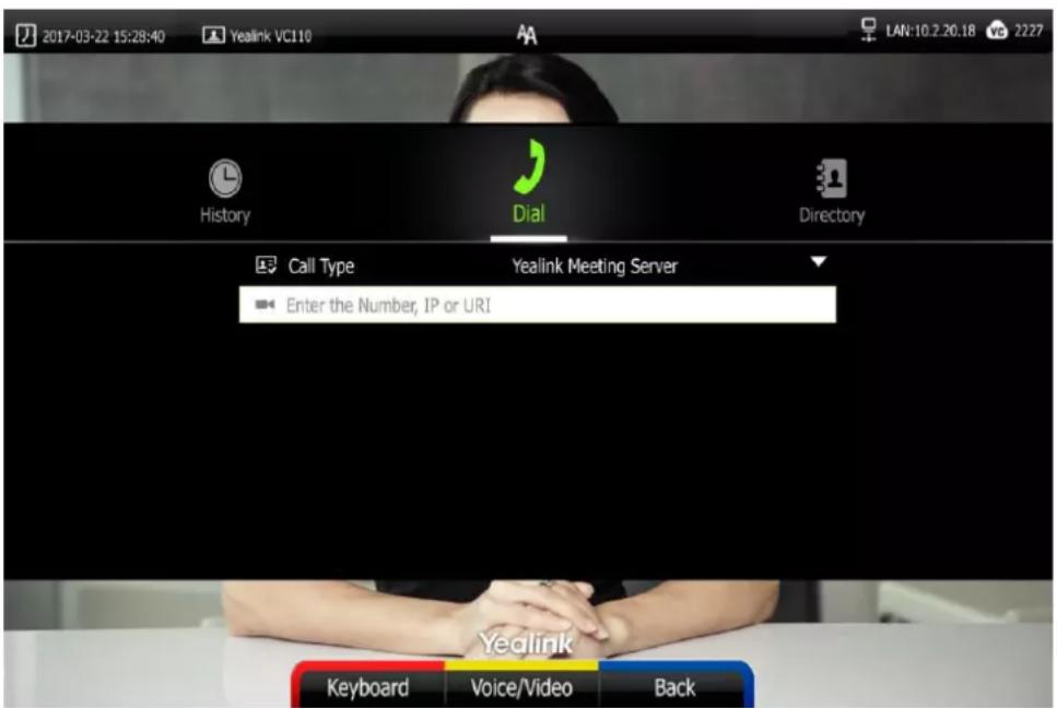
- Press (Voice/Video soft key) to change call mode.
- Press OK or
YMS Video Conference
When you register a YMS account, you can use YMS video conference feature.
There are two types of YMS video conference:
- Scheduled conference: You should schedule the conference using the Yealink Meeting Server or Microsoft Outlook software.
- Permanent Virtual Meeting Room: The permanent VMR is created by your administrator. You can join the permanent VMR at any time without a reservation.
Note
If more than one endpoint registered the same YMS account join the same conference, the former endpoint which joined the conference will leave the conference automatically. The conference only allows one of them to participant.
Scheduled Conference
You can schedule a conference using the Yealink Meeting Server or Microsoft Outlook software. After you schedule the conference, the scheduled conference will be added to all invitees' video conferencing endpoint. And invitee whose YMS account is associated with an email address, will receive an email about how to join the scheduled conference.
For more information on how to schedule a conference using the Yealink Meeting Server or Microsoft Outlook software, refer to Yealink Meeting Server User Guide. You can only view or join the scheduled conference via your VC110 video conferencing endpoint.
Viewing Conference Schedules
When you schedule a conference or receive an invitation to a conference, the conference details will appear on the idle screen and the menu.
If the conference organizer edits the conference content (e.g., time and participants) or cancel the conference via Yealink Meeting Server or Microsoft Outlook software after you have sent the invitation, the conference schedule will update in real time. Expired conferences will not be displayed on your video conferencing endpoint.
To view your conference schedules on the idle screen:
The idle screen displays the latest conference schedule (your upcoming or ongoing conference).
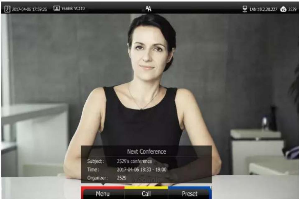
To view your conference schedules on the idle screen when you are sharing contents:
The idle screen will display the latest conference schedule (your upcoming or ongoing conference). And the conference schedule will be hidden in 5 seconds.
The conference schedule will appear again 30 minutes before the conference starts, and then be hidden automatically. And it will appear every 10 minutes until the conference starts. The conference schedule shows the conference details, as below:
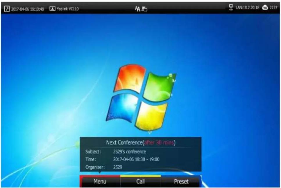
Note
Once you operate the VC110 video conferencing endpoint, the hidden conference schedule will appear.
To view conference schedules in the menu:
- Press (Menu soft key) to enter main menu.
- Press ◀ or ▶ to select the Schedule menu.
Your ongoing conferences and upcoming conferences are listed for the latest month.
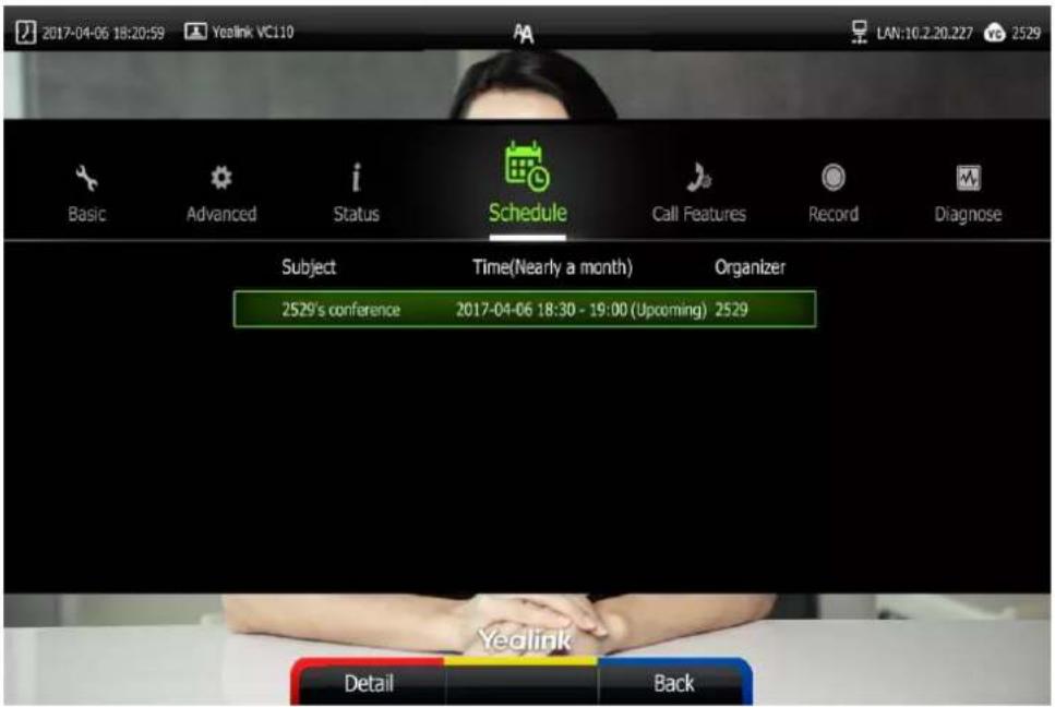
-
Press ▲r ▼ to scroll to the desired conference.
-
Press (Detail soft key) to view the detail.
Joining a Scheduled Conference
You can join a scheduled conference in following ways:
- Joining a scheduled conference from a conference reminder
- Joining a scheduled from a conference invitation
- Joining a scheduled conference from the conference schedule
• Dialing to join a scheduled conference
Note
By default, you can join a scheduled conference that is about to take place in 5 minutes or less. The administrator can configure when participants can join the scheduled conference. For more information, please contact your administrator.
Joining a Scheduled Conference from a Conference Reminder
A reminder pop-up is displayed 5 minutes before the conference starts. The reminder shows the main information of the schedule, including subject, date & time and organizer.

If you receive a conference reminder, you can do one of the following:
- Press ▲ or ▼ to scroll to Join, and press (ok).
- Press ▲ or ▼ to scroll to Cancel, and press OK to remove the reminder from the screen and stop all future reminders for this schedule.
Note
When the endpoint is in a call, the conference reminder will not pop up. After the call ends and the scheduled conference is still ongoing, the reminder will pop up. But if the scheduled conference ends, the reminder will not pop up.
Joining a scheduled Conference from a Conference Invitation
The administrator can configure the conference invitation feature on the Yealink Meeting Server, When the scheduled conference begins, the VC110 endpoint will receive a call that invites you to join the scheduled conference. For more information on how to configure the conference invitation feature, refer to YMS_Administrator Guide.
When the scheduled conference begins, the endpoint receives a conference invitation:

If you receive a conference invitation, you can do one of the following:
- Press ▲ or ▼ to scroll to Answer, and press OK to join the scheduled conference.
- Press ▲ or ▼ to scroll to Reject, and press (OK) to remove the invitation.
Note
If you enable the auto answer feature, the endpoint will join the scheduled conference automatically once it receives a conference invitation.
Joining a Scheduled Conference from Conference Schedules
You can join a scheduled conference from the conference schedules before the conference ends.
To join a scheduled conference from conference schedules:
-
Press (Menu soft key) to enter main menu.
-
Press ◀ or ▶ to select the Schedule menu.
Your ongoing conferences and upcoming conferences are listed for the latest month.
- Press ▲ or ▼ to scroll to the desired conference.
When the conference is about to take place in 5 minutes or less, a (Join soft key) appears by default.

- Do one of the following to join the conference:
- Press (Join soft key).
- Press (Detail soft key) to view the detail, and then press (Join soft key).
Dialing into a Scheduled Conference
If you schedule a conference or you are invited to a scheduled conference, you can obtain the conference information in following ways:
- Invitee will receive an email, which includes the IP address, conference ID and conference password and the way of joining a scheduled conference..
| Hello,2529 invites you to join video conference! |
| Subject: VC800 Product TrainingTime: 2017-06-08 09:30:00 ~ 2017-06-08 10:00:00 (UTC+08:00)Location : 234234ID: 61089Password: 749396 |
| The way to join conference:1) One-button to join conference from Yealink VC device which receives conference reminder;2) The device which has registered YMS account, please follow the voice prompt to enter conference ID 61089 & password 749396 , and end with # key;3) The device which hasn't registered YMS account, please dial 10.2.62.200 first, then follow the voice prompt to enter conference ID 61089 & password 749396, and end with # key;4) To join from a SIP device, please dial 61089**749396@10.2.62.200 and join the conference.5 ) To join from a H.323 device, please dial 10.2.62.200##61089**749396 and join the conference. |
| Description:Do not be late |
- VC110 video conferencing endpoint will display conference information, which includes the conference ID and conference password. For more information, refer to_Viewing Conference Schedules_on page 119.
- Contact the conference participants.
To dial into the scheduled conference, do one of the following:
- If you have registered a YMS account and you are invited to join the scheduled conference, you can dial the conference ID to join the conference.
Obtain the conference information from your VC110 video conferencing endpoint or your email address.
- If you have registered a YMS account but you are not invited to join the scheduled conference, you can dial the conference ID, and then follow the voice prompt to enter the conference password to join the conference.
Obtain the conference information from the other conference participants.
- If you do not register a YMS account, you can dial IP address of the server first, and then follow the voice prompt to enter the conference ID and conference password to join the conference.
Obtain the conference information from the other conference participants.
- To join from a SIP device, please dial conference ID** conference password@IP address of the server to join the conference.
Obtain the conference information from your email address or other conference participants.
• To join from a H.323 device, please dial IP address of the server##conference
ID**conference password to join the conference.
Obtain the conference information from your email address or other conference participants.
Note If the endpoint fails to join the scheduled conference, please refer to General Issues on page
Permanent Virtual Meeting Room
The administrator can configure the permanent VMR via the Yealink Meeting Server. You can join the permanent VMR at any time, without a reservation.
You can enter a permanent VMR in following ways:
• Dialing from the Yealink Enterprise Directory
• Dialing to enter a permanent VMR
Join a Permanent VMR from the Yealink Enterprise Directory
The administrator can determine whether synchronize the permanent VMR to the VC110. It is enabled by default.
To place a call to a permanent VMR via the remote control:
- Press □ (Call soft key).
- Press ◀ or ▶ to select the Directory menu.
- Select Enterprise directory from the pull-down list of the All Contacts.
- Select the desired permanent VMR.

- Press ok or
To place a call to a permanent VMR via the VCP40 phone:
-
Press the Directory soft key to enter the Directory list.
-
Press ▲ or ▼ to select Enterprise directory.
-
Press the Enter soft key or (OK) to view the contacts in the selected directory.
-
Press ▲ or ▼ to select the desired permanent VMR.
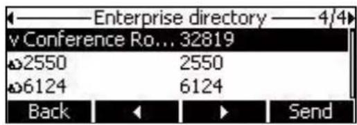
- Press the Send soft key, or ok to call the contact.
Dialing to Join a Permanent Virtual Meeting Room
Do one of the following to enter a permanent VMR.
a) If you register a YMS account, dial the conference ID to join the permanent VMR.
b) If you do not register a YMS account and the permanent VMR requires no password:
- Dial conference ID**@IP address of the server to join the permanent VMR.
- Dial IP address of the server ##conference ID** to join the permanent VMR.
c) If you do not register a YMS account and the permanent VMR requires a password:
- Dial conference ID**conference password@IP address of the server to join the permanent VMR.
- Dial IP address of the server ##conference ID**conference password to join the permanent VMR.
Applying for Speaking
There are two modes for scheduled conference and permanent VMR: Discussion mode and Training mode.
In Discussion mode, participants can speak freely. In Training mode, all guests are muted automatically except the moderator (or the organizer). Guests need to wait for the moderator to appoint lecturers. If guests want to speak, they should apply for speaking. Only when the moderator allows the request, can they speak freely.
Note
The conference mode can be configured by administrator on the Yealink Meeting Server only.
To apply for speaking:
When enter the Training mode conference, muted participants' display device prompts: "Please press 🤒 to apply for speaking" in first 30 seconds.
- Press ☐ on the remote control or press ☐ on the video conferencing phone.
The applicant's display device prompts " Apply for speaking".
The moderator will deal with the application on the Yealink Meeting Server. For more information, refer to Yealink Meeting Server User Guide.
Leaving the Conference
All participants can leave the conference at any moment.
To leave the conference via the remote control:
- Press
Other participants remain connected.
Using the StarLeaf Cloud Platform
You can log into the StarLeaf Cloud platform.
When you place a call using the StarLeaf Cloud account, you can:
- Call the other StarLeaf Cloud account to establish a point to point call.
- Call the meeting ID to join the Virtual Meeting Rooms.
- Call between StarLeaf Cloud account and Microsoft Skype for Business/Lync account.
Dialing StarLeaf Cloud Numbers
To dial StarLeaf Cloud numbers via the remote control:
-
Press □ (Call soft key) or □ to enter the dialing screen.
-
Select the registered StarLeaf Cloud number from the pull-down list of Call Type.
-
Enter a StarLeaf Cloud number using the keypad or the on-screen keyboard.

-
Press (Voice/Video soft key) to change call mode.
-
Press OK or √.
Joining the StarLeaf Meeting
To join the StarLeaf meeting via the remote control:
-
Press □ (Call soft key) or √ to enter the dialing screen.
-
Select the registered StarLeaf Cloud number from the pull-down list of Call Type.
-
Enter the meeting ID using the keypad or the on-screen keyboard.
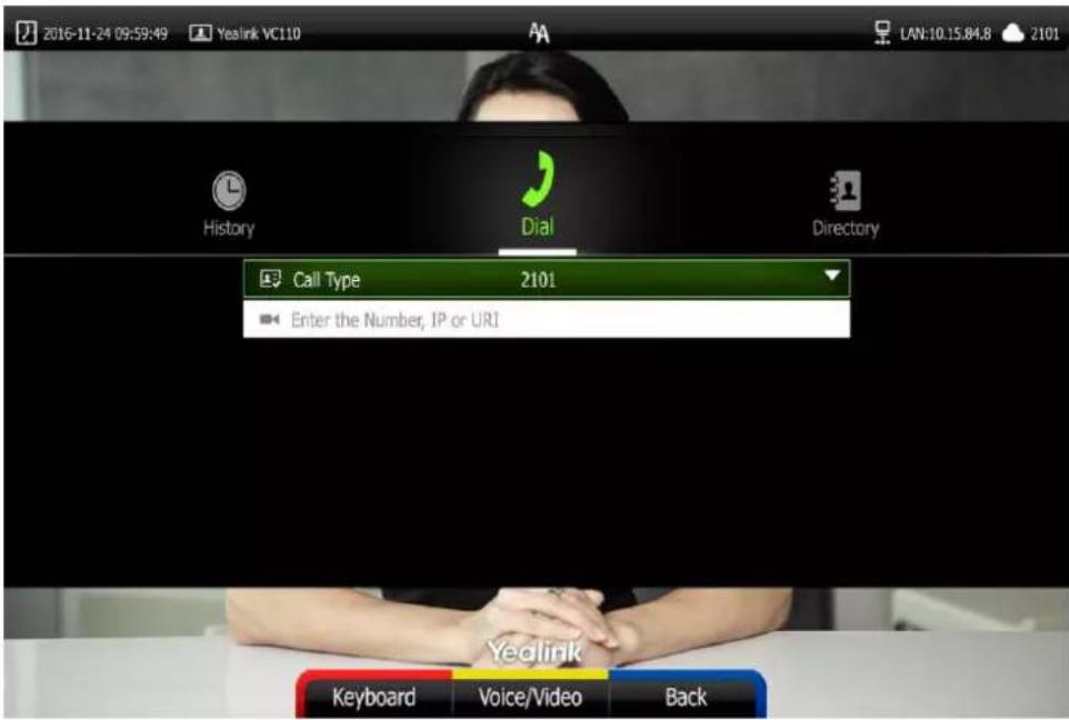
-
Press (Voice/Video soft key) to change call mode.
-
Press OK or 📋 to join the StarLeaf meeting.
Using the Zoom Cloud Platform
You can log into the Zoom Cloud platform, and join the Zoom meeting.
Joining the Zoom Meeting
To join the Zoom meeting:
-
Press □ (Call soft key) or ▼ to enter the dialing screen.
-
Select Zoom from the pull-down list of Call Type before calling.
-
Enter the meeting ID using the keypad or the on-screen keyboard.
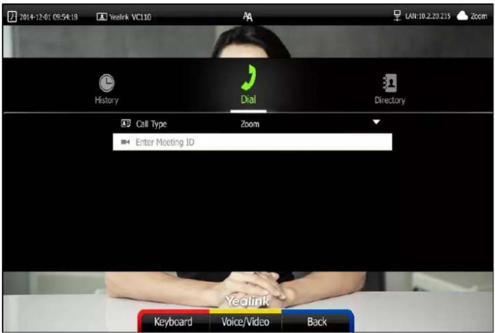
-
Press □ (Voice/Video soft key) to change call mode.
-
Press OK or √
You will enter the Zoom welcome screen.
- Follow the voice prompt to join the Zoom meeting.
Note
If you enter nothing or enter wrong information, you can still be sent to the Zoom welcome screen.
Using the BlueJeans Cloud Platform
You can log into the BlueJeans Cloud platform, and join the BlueJeans meeting.
Joining the BlueJeans Meeting
To join the BlueJeans meeting:
-
Press □ (Call soft key) or □ to enter the dialing screen.
-
Select BlueJeans from the pull-down list of Call Type before calling.
-
Enter the meeting ID using the keypad or the on-screen keyboard.
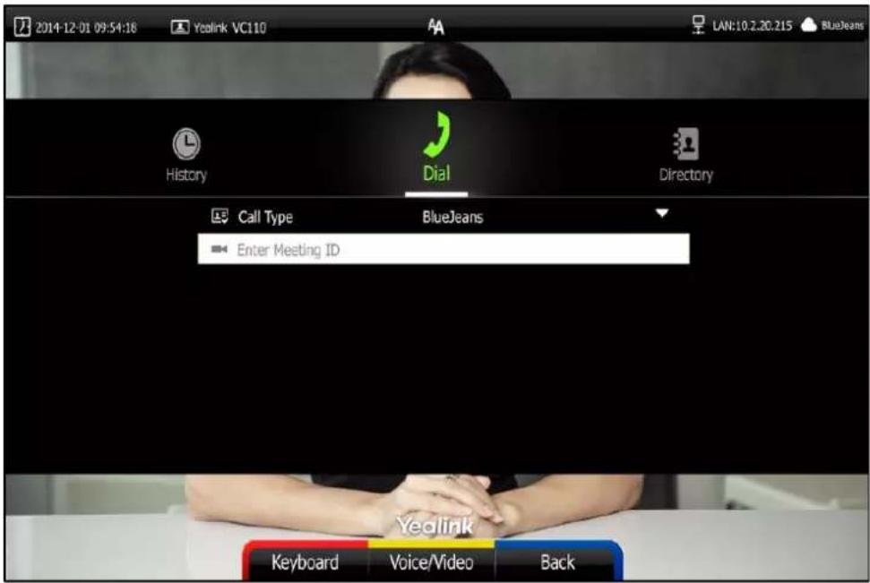
-
Press (Voice/Video soft key) to change call mode.
-
Press OK or √
You will enter the BlueJeans welcome screen.
- Follow the voice prompt to join the BlueJeans meeting.
Note
If you enter nothing or enter wrong information, you can still be sent to the BlueJeans welcome screen.
Using the Pexip Platform
You can register the Pexip account.
When you place a call using the Pexip account, you can:
- Call the device alias to establish a point to point call.
- Call the aliases to join the Virtual Meeting Rooms, Virtual Auditoriums or Virtual Receptions.
- Call between Pexip account and Microsoft Skype for Business/Lync account.
Dialing Pexip Alias
To dial Pexip alias using the remote control:
-
Press □ (Call soft key) or ▼ to enter the dialing screen.
-
Select the registered alias.
-
Enter the device alias or URI using the keypad or the on-screen keyboard.

-
Press □ (Voice/Video soft key) to change call mode.
-
Press OK or
Joining the Pexip Meeting
To join the Pexip meeting:
-
Press □ (Call soft key) or √ to enter the dialing screen.
-
Select the registered alias.
-
Enter the conference alias or URI using the keypad or the on-screen keyboard.

-
Press (Voice/Video soft key) to change call mode.
-
Press OK or
-
Follow the voice prompt to join the Pexip meeting.
Using the Mind Platform
You can log into the Mind platform, and join the Mind meeting.
Joining the Mind Meeting
To join the Mind meeting:
-
Press □ (Call soft key) or ⬇ to enter the dialing screen.
-
Select Mind from the pull-down list of Call Type before calling.
-
Enter the meeting ID using the keypad or the on-screen keyboard.
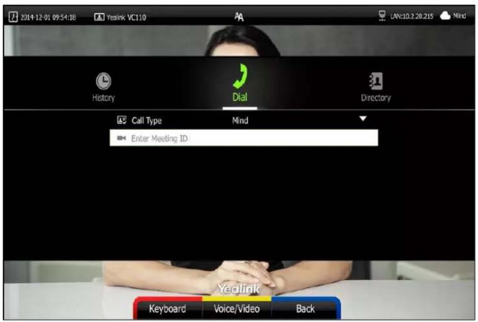
-
Press □(Voice/Video soft key) to change call mode.
-
Press OK or
-
Follow the voice prompt to join the Mind meeting.
Using the Custom Platform
When you register a custom account, you can use the corresponding platform feature.
Using the VCM60 Video Conferencing Wireless Microphone
This chapter provides basic operating instructions for the VCM60 video conferencing wireless microphone. Topics include:
- Placing the VCM60
- Turning On or Off the VCM60
- Connecting VCM60 to the Video Conferencing Endpoint
- Standby Mode
- Muting or Unmuting the VCM60
• Viewing VCM60 Information - Registering and Unregistering the VCM60
- Charging the VCM60
• VCM60 Working Frequency
If you require additional information or assistance with your new phone, contact your system administrator.
Placing the VCM60
The VCM60 has a rubber pads on its base to prevent it from sliding. You can place the VCM60 on a conference table. Do the following to ensure optimal voice quality:
- For registering to the dongle successfully, make sure the VCM60 video conferencing wireless microphone is less than 30 meters distant from the dongle.
- Place the VCM60 on a stable surface and keep it away from obstacles so that it can effectively pick up sounds.
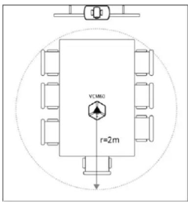
Turning On or Off the VCM60
There is a power switch on the bottom of the VCM60. Turn on the power switch to start the VCM60. After the VCM60 starts, it registers with the paired dongle automatically. You can turn off this switch if the VCM60 is not in use for a long period of time.
Connecting VCM60 to the Video Conferencing
Endpoint
To ensure good voice quality, VCM60 video conferencing wireless microphone can be connected to the VC110 video conferencing endpoint to act as the audio input device.
To connect the VCM60 to the VC110 video conferencing endpoint, do the following:
- Connect the dongle to one of the USB ports on the VC110 all-in-one unit.

The display device prompts "Dongle connected!", and the (unregistered) icon appears on the status bar.

- Turn on the VCM60.
The VCM60 registers with the dongle automatically. If successful, the (unregistered) icon will change to (registered). Currently capacity appears on the right side of the icon. When the last idle time is less than 1 hour, please charge the VCM60. For more information, refer to Charging the VCM60 on page 143.

To remove the VCM60 from the VC110 video conferencing endpoint, do the following:
- Remove the dongle from the VC110 all-in-one unit.
The display device prompts "Dongle remove!". And the icon disappears from the status bar.

Standby Mode
The VCM60 supports two standby modes: online standby and offline standby.
Online standby:
- When registering with dongle successfully, the VCM60 enters online standby mode and the mute indicator LED changes to green and is in breathing state.
Offline standby:
- If VC110 video conferencing endpoint encounters poor signal, wireless interference or is powered off, the VCM60 may lose connection with the dongle. In this case, the VCM60 will search for the dongle again, and the mute indicator LED fast flashes green. If dongle cannot be searched in 2 minutes, the VCM60 will enter offline standby mode automatically and the mute indicator LED slowly flashes orange.
- If VC110 video conferencing endpoint starts when the VCM60 is in offline standby mode, you need to tap the mute button to activate VCM60 to search for dongle again.
Muting or Unmuting the VCM60
There is a mute button on the top of the VCM6. If VCM60 works as the audio input device of the VC110 video conferencing endpoint, you can mute or unmute it in the following scenarios:
- If you do not want to have your voice broadcast during a conference, you can tap mute button to mute the VCM60.
- If you want to speak again during a conference, you can tap mute button to unmute the VCM60.
To mute the VCM60 during a call:
- Tap 📋 again to un-mute the call.
The mute indicator LED illuminates solid red. And the mute icon appears on the local video image.
To un-mute the VCM60 during a call:
- Tap again to un-mute the call.
The mute indicator LED illuminates solid green. And the mute icon disappears from the local video image.
Viewing VCM60 Information
When the dongle is connected to the USB port of the VC110 all-in-one unit, you can view VCM60 status via remote control or web user interface.
Available information of VCM60 includes:
- Dongle Status
- Dongle Version
- Micpod Status
- Micpod Version
- Mic Model
- MICPOD IPEI
- Battery Percent
- Idle Time (estimated standby time)
• Work Time(estimated working time)
To view the VCM60 information via the remote control:
-
Press (Menu soft key) to enter main menu.
-
Press ◀ or ▶ to select the Status menu.
-
Press ▲or▼ to scroll to select the Wireless Micpod, and then press OK.
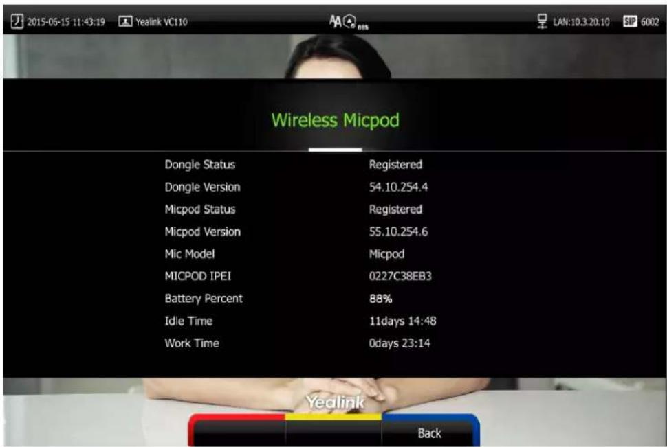
VCM60 information can be viewed via the web user interface at the path Status-> Wireless Micpod.
Registering and Unregistering the VCM60
The VCM60 video conferencing wireless microphone and dongle are automatically "paired" at the factory. But In following cases, you may need to deregister or register the VCM60 video conferencing wireless microphone manually.
• The device is broken, new VCM60 or new dongle need to be repaired.
• VCM60 and dongle need to be paired during the production.
You can only register and unregister the VCM60 via the web user interface. The web user interface will display the model and product ID of the dongle and video conferencing wireless microphone.
To deregister the VCM60 via web user interface:
- Click on Setting->Wireless Micpod.
2. Click DeRegisted.

3. Click Confirm to deregister the video conferencing wireless microphone.
The paired information will be cleared. The VCM60 video conferencing wireless microphone will enter offline standby mode and the mute indicator LED slowly flashes orange.
To register the VCM60 via web user interface:
1. Click on Setting->Wireless Micpod.
2. Click Search Mic.

The web user interface starts 120-second countdown for pairing the dongle and video conferencing wireless microphone.
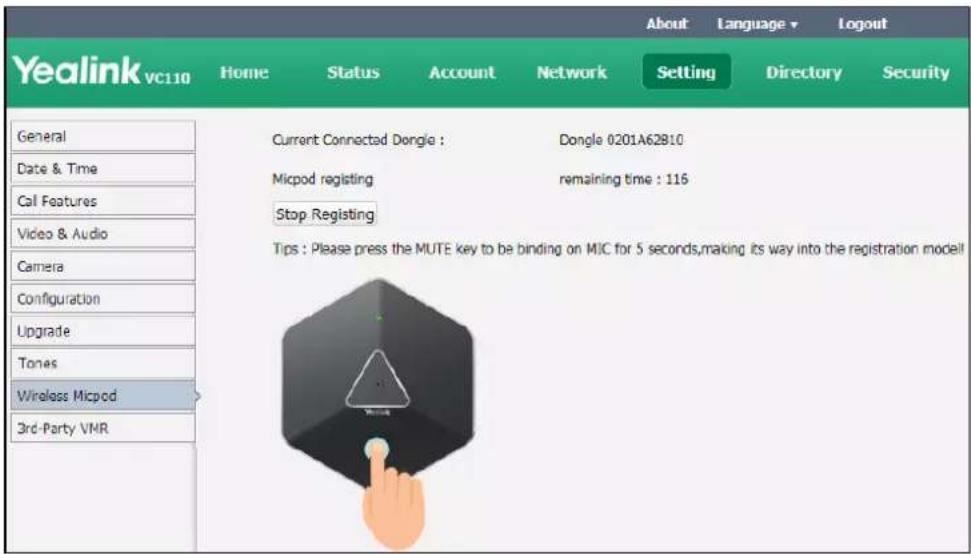
- Tap and hold the mute button on the VCM60 video conferencing wireless microphone for 5 seconds until the mute indicator LED flashes orange.
The VCM60 video conferencing wireless microphone and the dongle will be paired automatically. If this fails, the VCM60 will exit registration mode in 2 minutes.
Note
For registering to the dongle successfully, make sure the VCM60 video conferencing wireless microphone is less than 30 meters distant from the dongle, and isn't disturbed by obstacles.
Charging the VCM60
When the standby time of the VCM60 is less than 1 hour (the battery indicator LED flashes red), the icon appears on the status bar, and the display device prompts "The battery of wireless micpod is too low, please charge it in time!" every 15 minutes.
To charge the VCM60, connect it to a power adapter or a computer using the supplied USB cable.

The VPM60 can work normally during charging. If you charge the VCM60 when it is working, the display device prompts "The battery is charging!", and the (charging) icon appears on the status bar.

During charging, the battery LED indicator will flash green. And it will illuminate solid green when the battery capacity reaches 100%.
VCM60 Working Frequency
For reference, the Frequency/Channels of VCM60 used in each Region are tabulated below:
| Freq (MHz) | RF Carrier Index (DECT tester Numbering) | ||||||
| EU | Taiwan | US | LA | Korea | Brazil | Japan | |
| 1881.792 | 9 | 9 | |||||
| 1883.520 | 8 | 8 | |||||
| 1885.248 | 7 | 7 | |||||
| 1886.976 | 6 | 6 | |||||
| 1888.704 | 5 | 5 | |||||
| 1890.432 | 4 | 4 | |||||
| 1892.160 | 3 | 3 | |||||
| 1893.888 | 2 | 2 | |||||
| 1895.616 | 1 | 4(F1) | |||||
| 1897.344 | 0 | 3(F2) | |||||
| 1899.072 | 2(F3) | ||||||
| 1900.800 | 1(F4) | ||||||
| 1902.528 | 0(F5) | ||||||
| 1904.256 | |||||||
| 1905.984 | |||||||
| 1907.712 | |||||||
| 1909.440 | |||||||
| 1911.168 | 4 | ||||||
| 1912.896 | 9 | 3 | |||||
| 1914.624 | 8 | 2 | |||||
| 1916.352 | 7 | 1 | |||||
| 1918.080 | 6 | 0 | |||||
| 1919.808 | 5 | ||||||
| 1921.536 | 4 | 4 | |||||
| 1923.264 | 3 | 3 | |||||
| 1924.992 | 2 | 2 | |||||
| 1926.720 | 1 | 1 | |||||
| 1928.448 | 0 | 0 | |||||
| 1787.616 | 8 | ||||||
| 1789.344 | 7 | ||||||
| 1791.072 | 6 | ||||||
Using the VCM30 Video Conferencing
Microphone Array
This chapter provides basic operating instructions for the VCM30 video conferencing microphone array. Topics include:
- Placing the VCM30
- Muting or Unmuting the VCM30
• Viewing VCM30 Information
If you require additional information or assistance with your new phone, contact your system administrator.
Placing the VCM30
The VCM30 has a rubber pads on its base to prevent it from sliding. You can place the VCM30 on a stable surface and keep it away from obstacles so that it can effectively pick up sounds.
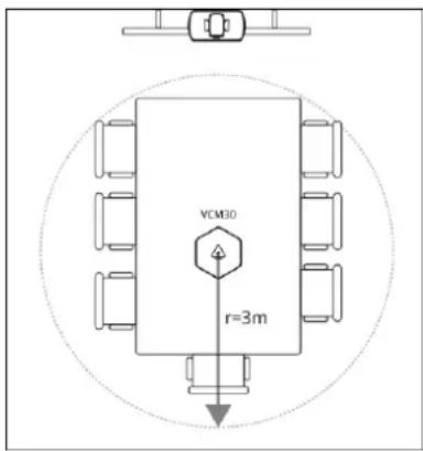
Muting or Unmuting the VCM30
There is a mute button on the top of the VCM30. You can mute or unmute it in the following scenarios:
- If you do not want to have your voice broadcast during a conference, you can tap the mute button to mute the VCM30.
- If you want to speak again during a conference, you can tap mute button to unmute the VCM30.
To mute the VCM30 during a call:
- Tap ♩ to mute the call.
The mute indicator LED illuminates solid red. And the mute icon appears on the local video image.
To un-mute the VCM30 during a call:
- Tap again to un-mute the call.
The mute indicator LED illuminates solid green. And the mute icon disappears from the local video image.
Viewing VCM30 Information
When the VCM30 is connected to the Audio In port of cable hub, you can view VCM30 status via the remote control or web user interface.
Available information of VCM30 includes:
- Status
- Model
- Hardware
- Serial Number
To view the VCM30 information via the remote control:
- Press (Menu soft key) to enter main menu.
- Press ◀or ▶ to select the Status menu.
- Press ▲ or ▼ to scroll to select the Wired Micpod, and then press OK.
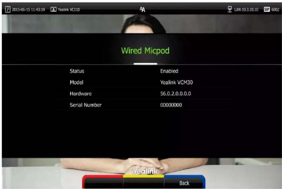
VCM30 information can be viewed via the web user interface at the path Status->Wired Micpod.
Using VCP41 with the PC or Mobile Device
You connect a PC or mobile device to your VCP41 video conferencing phone, so that the VCP41 can work as the audio input/output device of your PC or mobile device.
Connecting a PC or Mobile Device to the VCP41
You can connect a PC or mobile device to the VCP41 when your VC110 video conferencing endpoint, is placing a call or during a call.
To connect a PC or mobile device to your VCP41:
- Connect one end of the 3.5mm audio cable to the PC/mobile port on the VCP41 phone, and connect the other end to the headset jack on the mobile device or the AUX/MIC jack on the PC.

The icon will appear on the display device, and the icon will appear on the video conferencing phone.
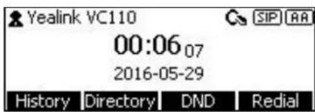
As a result, VCP41 will work as the audio input/output device of your PC or mobile device. For example, when the PC or mobile device is playing a video or music, you can listen to the audio on your VCP41. If your PC or mobile device receives an incoming call, you can use VCP41 to listen and speak.
Adjusting the Volume of the PC or Mobile Audio
When your PC or mobile device is during a call, you can adjust the output volume of the PC/mobile device via your VCP41.
To adjust the volume of the PC or mobile device:
- When your PC or mobile device is during a call, press - - + on the VCP41 to adjust the volume.
Removing the PC or Mobile Audio
To remove the PC or mobile device, disconnect the 3.5mm audio cable from the VCP41.
Troubleshooting
This chapter provides general troubleshooting information to help you solve problems you might encounter when using your VC110 endpoint. If you require additional information or assistance with your new phone, contact your system administrator.
Ensure the endpoint has not been physically damaged when experiencing a problem. Check whether the cables are loose and the connections are correct and secure. These are common causes of problems.
Endpoint Diagnostics
Diagnostic menus include:
- Audio Diagnose: Check whether the audio output device can pick up voice and play audio normally.
• Camera Diagnose: Check whether the camera can pan and change focus normally. - Ping: Check whether the endpoint can establish contact with the IP address that you specify.
- Trace Route: Display the route (path) and measure transit delays of packets across an Internet Protocol (IP) network.
Audio Diagnose:
- Press (Menu soft key) to enter main menu.
- Press ◀ or ▶ to select the Diagnose menu.
- Press ▲or ▼ to scroll to Audio Diagnose, and then press OK.
- Speak into the microphone.
- Check whether the microphone can pick up audio normally.
If the microphone picks up audio and plays back audio normally, it means that the audio works well.
- Press OK to stop audio diagnostics.
Camera Diagnose:
- Press (Menu soft key) to enter main menu.
- Press ◀ or ▶ to select the Diagnose menu.
- Press ▲or ▼ to scroll to Camera Diagnose, and then press OK.
- Press ▲ or ▼ to adjust the camera position.
- Press ⊖ or ⊕ to adjust the focus.
If the camera can move and zoom normally, it means that the camera is working well.
- Press (Back soft key) to stop camera diagnostics.
Network diagnosis:
-
Press (Menu soft key) to enter main menu.
-
Press ◀ or ▶ to select the Diagnose menu.
-
Press ▲ or ▼ to scroll to Ping, and then press OK.
-
Press ▲ or ▼ to select Start, and then press OK.
-
You can also enter any IP address (for example, the IP address of the remote endpoint) in the Ping field.
It measures the round-trip time from transmission to reception and reports errors and packet loss. The results of the test include a statistical summary of the response packets received, including the minimum, maximum, and the mean round-trip times.
- Press (Back soft key) to return to Diagnose menu.
Trace Route:
-
Press (Menu soft key) to enter main menu.
-
Press ◀ or ▶ to select the Diagnose menu.
-
Press ▲ or ▼ to scroll to Trace Route, and then press OK.
-
Press ▲ or ▼ to select Start, and then press OK
-
You can also enter any IP address (for example, the IP address of the remote endpoint) in the Trace Route field.
If the test is successful, the VC110 endpoint lists the hops between the endpoint and the IP address you entered. You can check whether congestion happens via the time cost between hops.
- Press (Back soft key) to return to Diagnose menu.
General Issues
Why can't the endpoint place a call?
- Check the network is available.
- When making a call using an account, check that the account is registered.
- Ensure the remote endpoint supports the same call protocol as the local endpoint. If you want to place a call using another protocol, refer to Call Protocol on page 79.
Why can't the endpoint receive calls?
- Check the network is available.
- When receiving a call using an account, check that the account is registered.
- Check that DND (Do Not Disturb) mode is deactivated on your endpoint. Refer to Do Not Disturb (DND) on page 96.
If the endpoint fails to join the scheduled conference, you need to:
- Check if the conference is expired.
- Check if you enter the wrong conference information.
- Check if the current time is more than 5 minutes before the scheduled start time.
Why does the endpoint leave the scheduled conference automatically when the conference is ongoing?
Checks whether more than one endpoint registered the same YMS account join the same conference. The conference only allows one of them to join the conference, the former endpoint which joined the conference will leave the conference automatically.
Why doesn't the display device display the time and date correctly?
Check whether you have configured the endpoint to obtain the time and date from the SNTP server automatically. If the endpoint fails to connect to the SNTP server, contact your system administrator for more information. You can also configure the time and date manually. For more information, refer to Date & Time on page 54.
How to obtain the IP address of the endpoint?
Three are three ways to obtain the IP address of the endpoint:
- The IP address of the endpoint is shown on the top right corner of the display device.
- Press (Menu soft key) on your remote control and select Network.
The display device shows the network information about the endpoint.
- Press OK on the video conferencing phone when the phone is idle and select Network. The LCD screen of the phone displays the network information about the endpoint.
Why the endpoint fails to conduct a video conference?
- Check the network is configured correctly and available, and that the display device doesn't create a network anomaly.
- Ensure that the local endpoint can ping the IP address of the remote endpoint.
- Ensure that the entered call information is correct.
- Ensure that the called party is powered on.
- Ensure that a call can be established between the local and the remote endpoint.
- Troubleshoot the problem according to the prompts.
Why does the endpoint fail to call the far site?
- Check whether the network of the local site is available.
-
Check whether the network of the far site is available.
-
Check whether the far site enables the DND feature.
- Check whether the accounts have been registered correctly, and the endpoint uses the appropriate account to call the far site.
- Ensure that the number you are calling is correct.
- Check whether the far site rejects your call.
- Check whether the firewall blocks the inbound traffics from the other site.
- Check whether the far site has already up to maximum call-in limitation.
- If the local site is forced to use encryption, ensure that the far site enables encryption too.
- Ensure that the far site supports the same call protocol as the local site.
Why does the endpoint fail to call the far site via IP address?
- Ensure that the network is connected correctly.
- Ping the IP address of the far site. Contact your system administrator if it fails.
Camera Issues
How to adjust room lighting?
You can alter the environmental lighting and background colors of your environment to obtain the best video quality. If light levels are too low you may consider adding artificial lighting. Reflected light from pale walls often produces excellent results.
Avoid the following situations:
- Direct sunlight on the display device, the background, or the camera lens which creates harsh contrasts.
- Colored lighting.
Why can't I adjust the camera angle and focus?
- You can adjust the camera when the endpoint is idle or during a call. The camera cannot be adjusted when the endpoint is in the menu screen.
- Ensure that the batteries in the remote control are in good working condition, and installed correctly.
- Aim the remote control at the sensor when you perform a task.
- Ensure that no objects are obstructing the sensor on the front of the camera.
- Ensure that the LED on the front of the camera flashes green when you use the remote control to perform a task.
- Ensure that what you are controlling is the local camera.
- Reboot the endpoint.
- If the above suggestions cannot solve your problem, perhaps the remote control is broken. You can contact your system administrator for help.
Why is the video quality bad?
- Ensure that the display device has suitable resolution.
- Check whether the packet has been lost. For more information on packet loss, refer to Call Statistics on page 100.
- Contact your administrator to adjust the camera brightness and white balance.
Display Issues
Why is there no video on the display device?
- Ensure that the display device is turned on.
- Ensure that the display device is properly connected to the VC110 all-in-one unit.
- Ensure that the VC110 all-in-one unit is turned on.
- Ensure that you have selected the correct video input source.
Why can't the display device start a presentation?
- Ensure that the PC is properly connected to the cable hub.
- Ensure that the PC is turned on.
- Contact your administrator for help.
Video & Audio Issues
Why can't I hear the audio during a call?
- Ensure that the endpoint has selected an available audio output device.
- Ensure that the proper volume level on the endpoint.
- Ensure that the microphone on the remote endpoint is not muted.
Why can't I hear a ring tone when receiving a call?
- Ensure that the endpoint has selected an available audio output device.
- Ensure that the ring volume is not set to 0. If it is, the 📄 icon will appear on the status bar of display device, and the 🔧 icon will appear on the LCD screen of the video conferencing phone.
- Adjust the ring volume when the endpoint is idle via the remote control or video conferencing phone. For more information, refer to Volume Settings on page 59.
- Ensure that the microphone of the remote endpoint is not muted.
Why can't I view the menu?
- Check whether the Display1 port of VC110 all-in-one unit is connected to the HDMI port on the display device.
Why can't I hear the other site clearly during a call?
- Ensure that the speaker volume of the far site is not set too low.
- Muffled audio reception from the far side may be caused by highly reverberant rooms. Speak in close proximity to the phone.
- Adjust the priority order for your audio codec if you have chosen a low-bandwidth audio codec to be first.
- For best results, ensure that the caller is using a Yealink video conferencing endpoint. Audio quality from your VC110 video conferencing endpoint will vary when calling a non-Yealink endpoint.
- Dust and debris may cause audio quality. Do not use any kind of liquid or aerosol cleaner on the phone. A soft, slightly damp cloth should be sufficient to clean the top surface of the phone if necessary.
Why is the voice quality poor?
Users may receive poor voice quality during a call, such as intermittent voice, low volume, echo or other noise. It is difficulty to diagnosis the root causes of the voice anomalies. The possible reasons are:
- Users sit too far from or near to the microphone.
- The audio pickup device is moved frequently.
- Intermittent voice is probably caused by voice packet loss or jitter. Voice packet loss may occur due to network congestion. Jitter may occur due to information reorganization of the transmission or receiving equipment, such as, delay processing, retransmission mechanism or buffer overflow.
- Noise devices, such as computers or fans, may make it difficult to hear each other's voices clearly.
- Wires may also cause this problem. Replace the old with the new cables, and then reconnect to check whether the new cables provide better connectivity.
Endpoint Maintenance
How to reboot the phone?
-
Press (Menu soft key) to enter main menu.
-
Press ◀ or ▶ to scroll to the Advanced menu.
-
Enter admin password (default password: 0000) in the Admin Password field.
- Press OK or press Enter soft key).
- Press ▲ or ▼ to scroll to Reboot & Reset, and then press OK.
- Press ▲or▼ to scroll to Reboot, and then press OK. The display device prompts "Reboot the endpoint?"

- Select OK, and then press OK.
You can reboot the endpoint via the web user interface at the path
Setting->Upgrade->Reboot.
How to export PCAP trace?
We may need you to provide a PCAP trace to help analyze your problem. Exporting PCAP trace is configurable via the web user interface and remote control.
To export a PCAP trace via the web user interface:
-
Click on Settings->Configuration.
-
Click Start to begin capturing signal traffic.
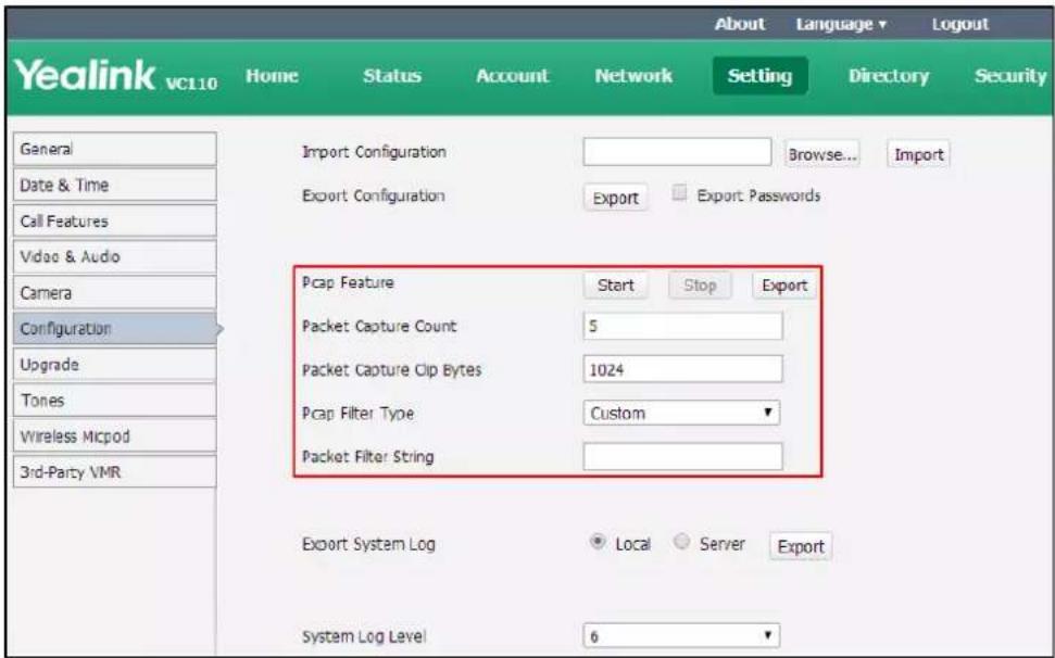
- Recreate the error to be documented in the trace.
- Click Stop to stop the capture.
- Click Export to open the file download window, and then save the file to your local endpoint.
You can also configure the count, bytes and filter type of the packet before exporting PCAP trace. For more information, contact your system administrator.
To export a PCAP trace via the remote control:
Before capturing packets, you need to insert a USB flash drive to the USB port on the VC110 all-in-one unit to store packets. Make sure the USB feature is enabled.
- Long press when the endpoint is idle or during a call.
The display device prompts "Onekey-capture is running, press the Backspace key for 2s to turn off it?".
- Long press ◀ for 2 seconds to stop capturing packets.
The packets are saved in the yealink.debug folder on your USB flash driver.
How to export system log?
We may need you to provide your phone configurations to help analyze your problems. You can export the system log to the local endpoint or designated log server.
To export the system log to a local PC via the web user interface:
- Click on Settings->Configuration.
- Mark the Local radio box in the Export System Log field.
- Select 6 from the pull-down list of System Log Level.
The default system log level is 6.
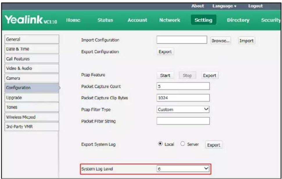
- Click Confirm to accept the change.
The web user interface prompts "Operating...Please wait...".
Export the system log referring to the following steps.
- Recreate the error to be documented in the trace.
- Click Export to save the file to your local endpoint.
How to export/import the endpoint configurations?
We may need you to provide your endpoint configurations to help analyze problems. In some instance, you may need to import configurations to your endpoint.
To export the endpoint configurations via the web user interface:
- Click on Setting->Configuration.
2. Click Export.
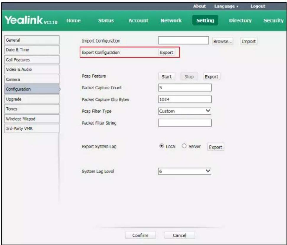
3. Click Confirm to export the configurations.
To import the endpoint configurations via the web user interface:
- Click on Setting->Configuration.
- Click Browse to locate a configuration file from your local system.

- Click Import to import the configuration file.
Note
The file format of configuration file must be *.bin.
How to upgrade firmware?
To upgrade firmware via the web user interface:
- Click on Setting->Upgrade.
- Click Browse to locate the firmware from your local system.
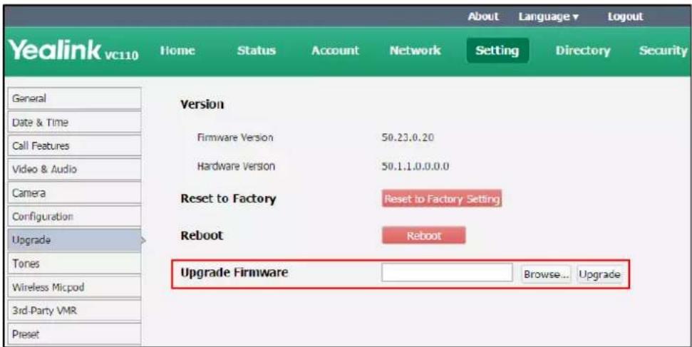
- Click Upgrade to upgrade the firmware.
The browser pops up the dialog box "Firmware will be updated. It will take 5 minutes to complete. Please don't power off!".
- Click Confirm to confirm upgrading.
How to reset the endpoint?
Reset the endpoint to factory configurations after you have tried all appropriate troubleshooting suggestions but have still not solved the problem. You need to note that all customized settings will be overwritten after reset. You can reset the endpoint via the remote control or web user interface.
To reset the endpoint via the remote control:
- Press (Menu soft key) to enter main menu.
- Press ◀ or ▶ to scroll to the Advanced menu.
- Enter admin password (default password: 0000) in the Admin Password field.
- Press OK or Press (Enter soft key).
- Press ▲ or ▼ to scroll to Reboot & Reset, and then press OK.
- Press ▲ or ▼ to scroll to Reset, and then press OK.
The display device prompts "Reset to Factory?"

7. Select OK, and then press OK.
The endpoint reboots automatically, the LCD screen of the video conferencing phone prompts "Rebooting Please wait...". The phone will be reset to factory successfully after startup.
Note
Reset of the endpoint may take a few minutes. Do not power off until the phone starts up successfully.
Resetting the endpoint is configurable via the web user interface at the path
Setting->Upgrade->Reset to Factory.
Regulatory Notices
Service Agreements
Contact your Yealink Authorized Reseller for information about service agreements applicable to your product.
Limitations of Liability
TO THE FULL EXTENT ALLOWED BY LAW, YEALINK EXCLUDES FOR ITSELF AND ITS SUPPLIERS ANY LIABILITY, WHETHER BASED IN CONTRACT OR TORT (INCLUDING NEGLIGENCE), FOR INCIDENTAL, CONSEQUENTIAL, INDIRECT, SPECIAL, OR PUNITIVE DAMAGES OF ANY KIND, OR FOR LOSS OF REVENUE OR PROFITS, LOSS OF BUSINESS, LOSS OF INFORMATION OR DATA, OR OTHER FINANCIAL LOSS ARISING OUT OF OR IN CONNECTION WITH THE SALE, INSTALLATION, MAINTENANCE, USE, PERFORMANCE, FAILURE, OR INTERRUPTION OF ITS PRODUCTS, EVEN IF YEALINK OR ITS AUTHORIZED RESELLER HAS BEEN ADVISED OF THE POSSIBILITY OF SUCH DAMAGES, AND LIMITS ITS LIABILITY TO REPAIR, REPLACEMENT, OR REFUND OF THE PURCHASE PRICE PAID, AT YEALINK'S OPTION. THIS DISCLAIMER OF LIABILITY FOR DAMAGES WILL NOT BE AFFECTED IF ANY REMEDY PROVIDED HEREIN SHALL FAIL OF ITS ESSENTIAL PURPOSE.
Safety Instructions
Save these instructions. Read these safety instructions before use!
The following basic safety precautions should always be followed to reduce risk of fire, electrical shock, and other personal injury.

General Requirements
- Before you install and use the device, read the safety instructions carefully and monitor the situation during operation.
- During the process of storage, transportation, and operation, please always keep the device dry and clean.
- During the process of storage, transportation, and operation, please avoid collision and an impact to the device.
- Pleasedo not attempt to dismantle the device by yourself. In case of any discrepancy, please contact the appointed maintenance center for repair.
- Without prior written consent, no organization or individual is permitted to make any change to the structure or the safety design of the device. Yealink is under no circumstance liable to consequences or legal issues caused by such changes.
- Please refer to the relevant laws and statutes while using the device. The legal rights of others should be respected as well.

Environmental Requirements
- Place the device in a well-ventilated place. Do not expose the device under direct sunlight.
- Keep the device dry and free of dust.
- Place the device on a stable and level platform.
- Please do not place any heavy objects on the device in case of damage and deformation caused by the heavy load.
- Keep at least 10 cm between the device and the closest object for heat dissipation.
- Do not place the device on or near any inflammable or fire-vulnerable object, such as rubber-made materials.
- Keep the device away from any heat source or bare fire, such as a candle or an electric heater.
- Keep the device away from any household appliance with a strong magnetic field or electromagnetic field, such as a microwave oven or a refrigerator.

Operating Requirements
- Do not let a child operate the device without guidance.
- Do not let a child play with the device or any accessory in case of accidental swallowing.
- Please only use package provided or authorized by the manufacturer.
- The power supply of the device shall meet the requirements of the input voltage of the device. Please only use the surge protection power socket provided.
- Before plugging or unplugging any cable, ensure that your hands are completely dry.
- Do not spill liquid of any kind on the product or use the equipment near water, for example, near a bathtub, washbowl, kitchen sink, wet basement or near a swimming pool.
- Do not tread on, pull, or over-bend any cable in case of malfunction of the device.
- During a thunderstorm, stop using the device and disconnect it from the power supply. Unplug the power plug and the Asymmetric Digital Subscriber Line (ADSL) twisted pair (the radio frequency cable) to avoid lightning strike.
- If the device is left unused for a rather long time, disconnect it from the power supply and unplug the power plug.
- When smoke or an abnormal noise or smell is emitted from the device, disconnect the device from the power supply, and unplug the power plug immediately. Contact the specified maintenance center for repair.
- Do not insert any object into equipment slots that is not part of the product or auxiliary product.
- Before connecting a cable, connect the grounding cable of the device first. Do not disconnect the grounding cable until you disconnect all other cables.

Cleaning Requirements
• Before cleaning the device, stop using it and disconnect it from the power supply.
• Use a piece of soft, dry and anti-static cloth to clean the device.
- Keep the power plug clean and dry. Using a dirty or wet power plug may lead to electric shock or other perils.
Restriction of Hazardous Substances
Restriction of Hazardous Substances (RoHS) is a Chinese government regulation which aims to restrict certain dangerous substances commonly used in electronic and electronic equipment.
The following table lists the names and content of the toxic and hazardous substances or elements probably contained in the products:
| Parts Name | Toxic or Hazardous Substance and Elements | |||||
| Lead (Pb) | Mercury (Hg) | Cadmium (Cd) | Hexavalent Chromium ( Cr+6 ) | Polybrominated Biphenyls (PBB) | Polybrominated Diphenyl Ethers (PDBE) | |
| Plastic and Polymeric Parts | O | O | O | O | O | O |
| Metal Parts | X | O | O | O | O | O |
| PCBA | X | O | O | O | O | O |
| Cables and Cable Assemblies | O | O | O | O | O | O |
| LCD Screen | O | O | O | O | O | O |
| Batteries | O | O | O | O | O | O |
| Packing Material | O | O | O | O | O | O |
O: Indicates that toxic substances contained in all homogeneous materials in this product are below the limit requirement in GB/T26572-2011 standard.
X: Indicates that toxic substances contained in all homogeneous materials in this product are above the limit requirement in GB/T26572-2011 standard.
This table lists the toxic and hazardous substances contained in the machine. Based on the material type, the data is provided by the supplier and has already been validated by Yealink company.
Some harmful substances contained in the material cannot be replaced according to the current technology. We constantly strive to improve our products.
Appendix A - Time Zones
| Time Zone | Time Zone Name |
| -11:00 | Samoa |
| -10:00 | United States-Hawaii-Aleutian |
| -10:00 | United States-Alaska-Aleutian |
| -09:30 | French Polynesia |
| -09:00 | United States-Alaska Time |
| -08:00 | Canada(Vancouver, Whitehorse) |
| -08:00 | Mexico(Tijuana, Mexicali) |
| -08:00 | United States-Pacific Time |
| -07:00 | Canada(Edmonton, Calgary) |
| -07:00 | Mexico(Mazatlan, Chihuahua) |
| -07:00 | United States-Mountain Time |
| -07:00 | United States-MST no DST |
| -06:00 | Canada-Manitoba(Winnipeg) |
| -06:00 | Chile(Easter Islands) |
| -06:00 | Mexico(Mexico City, Acapulco) |
| -06:00 | United States-Central Time |
| -05:00 | Bahamas(Nassau) |
| -05:00 | Canada(Montreal, Ottawa, Quebec) |
| -05:00 | Cuba(Havana) |
| -05:00 | United States-Eastern Time |
| -04:30 | Venezuela(Caracas) |
| -04:00 | Canada(Halifax, Saint John) |
| -04:00 | Chile(Santiago) |
| -04:00 | Paraguay(Asuncion) |
| -04:00 | United Kingdom-Bermuda(Bermuda) |
| -04:00 | United Kingdom(Falkland Islands) |
| -04:00 | Trinidad&Tobago |
| -03:30 | Canada-New Foundland(St.Johns) |
| -03:00 | Denmark-Greenland(Nuuk) |
| -03:00 | Argentina(Buenos Aires) |
| -03:00 | Brazil(no DST) |
| -03:00 | Brazil(DST) |
| -02:30 | Newfoundland and Labrador |
| -02:00 | Brazil(no DST) |
| -01:00 | Portugal(Azores) |
| 0 | GMT |
| 0 | Greenland |
| 0 | Denmark-Faroe Islands(Torshavn) |
| 0 | Ireland(Dublin) |
| 0 | Portugal(Lisboa, Porto, Funchal) |
| 0 | Spain-Canary Islands(Las Palmas) |
| 0 | United Kingdom(London) |
| 0 | Morocco |
| +01:00 | Albania(Tirane) |
| +01:00 | Austria(Vienna) |
| +01:00 | Belgium(Brussels) |
| +01:00 | Caicos |
| +01:00 | Chad |
| +01:00 | Spain(Madrid) |
| +01:00 | Croatia(Zagreb) |
| +01:00 | Czech Republic(Prague) |
| +01:00 | Denmark(Kopenhagen) |
| +01:00 | France(Paris) |
| +01:00 | Germany(Berlin) |
| +01:00 | Hungary(Budapest) |
| +01:00 | Italy(Rome) |
| +01:00 | Luxembourg(Luxembourg) |
| +01:00 | Macedonia(Skopje) |
| +01:00 | Netherlands(Amsterdam) |
| +01:00 | Namibia(Windhoek) |
| +01:00 | Poland (Warsaw) |
| +02:00 | Estonia(Tallinn) |
| +02:00 | Finland(Helsinki) |
| +02:00 | Gaza Strip(Gaza) |
| +02:00 | Greece(Athens) |
| +02:00 | Israel(Tel Aviv) |
| +02:00 | Jordan(Amman) |
| +02:00 | Latvia(Riga) |
| +02:00 | Lebanon(Beirut) |
| +02:00 | Moldova(Kishinev) |
| +02:00 | Russia(Kaliningrad) |
| +02:00 | Romania(Bucharest) |
| +02:00 | Syria(Damascus) |
| +02:00 | Turkey(Ankara) |
| +02:00 | Ukraine(Kyiv, Odessa) |
| +03:00 | East Africa Time |
| +03:00 | Iraq(Baghdad) |
| +03:00 | Russia(Moscow) |
| +03:30 | Iran(Teheran) |
| +04:00 | Armenia(Yerevan) |
| +04:00 | Azerbaijan(Baku) |
| +04:00 | Georgia(Tbilisi) |
| +04:00 | Kazakhstan(Aktau) |
| +04:00 | Russia(Samara) |
| +04:30 | Afghanistan(Kabul) |
| +05:00 | Kazakhstan(Aqtobe) |
| +05:00 | Kyrgyzstan(Bishkek) |
| +05:00 | Pakistan(Islamabad) |
| +05:00 | Russia(Chelyabinsk) |
| +05:30 | India(Calcutta) |
| +05:45 | Nepal(Katmandu) |
| +06:00 | Kazakhstan(Astana, Almaty) |
| +06:00 | Russia(Novosibirsk, Omsk) |
| +06:30 | Myanmar(Naypyitaw) |
| +07:00 | Russia(Krasnoyarsk) |
| +07:00 | Thailand(Bangkok) |
| +08:00 | China(Beijing) |
| +08:00 | Singapore(Singapore) |
| +08:00 | Australia(Perth) |
| +08:00 | Russia(Irkutsk, Ulan-Ude) |
| +08:45 | Eucla |
| +09:00 | Korea(Seoul) |
| +09:00 | Japan(Tokyo) |
| +09:00 | Russia(Yakutsk, Chita) |
| +09:30 | Australia(Adelaide) |
| +09:30 | Australia(Darwin) |
| +10:00 | Australia(Sydney, Melbourne, Canberra) |
| +10:00 | Australia(Brisbane) |
| +10:00 | Australia(Hobart) |
| +10:00 | Russia(Vladivostok) |
| +10:30 | Australia(Lord Howe Islands) |
| +11:00 | New Caledonia(Noumea) |
| +11:00 | Russia(Srednekolymsk Time) |
| +11:30 | Norfolk Island |
| +12:00 | New Zealand(Wellington, Auckland) |
| +12:00 | Russia(Kamchatka Time) |
| +12:45 | New Zealand(Chatham Islands) |
| +13:00 | Tonga(Nukualofa) |
| +13:30 | Chatham Islands |
| +14:00 | Kiribati |
Index
A
About This Guide v
Adding a Local Contact from the Call History
List 78
Adding Contacts 64
Answering or Rejecting Calls 94
Appendix A - Time Zones 170
Audio Input Device 83
Audio Output Device 82
Audio Settings 82
Auto Answer 95
Automatic Sleep Time 49
B
Backlight 50
Bandwidth Settings 80
Blacklist 50
c
Cable Hub 11
CPE80 Expansion Microphone 15
Call History Management 73
Call Mute 99
Call Protocol 79
Call Statistics 100
Camera Issues 157
Changing Video Input Source 101
Changing Video Layout 112
Chapters in This Guide v
Charging the VCM60 143
Connecting VCM60 to the Video Conferencing
Endpoint 137
Controlling Far-end Camera 86
Customizing VC110 Video Conferencing
Endpoint 48
D
Date & Time 54
Deleting an entry from the call history list 76
Deleting Local Contacts 67
Directory 63
Display Issues 158
Dialing Pexip Alias 132
Dialing StarLeaf Cloud Accounts 128
Dialing Yealink Cloud Accounts 116
Documentations vi
Do Not Disturb (DND) 96
E
Editing Local Contacts 66
Ending Calls 98
Endpoint Component Instructions 7
Endpoint Connection and Installation 28
Endpoint Diagnostics 154
Endpoint Maintenance 159
Endpoint Status 45
Entering Data and Editing Fields 44
F
Far-end Camera Control 85
G
General Issues 155
Getting Started 28
H
Hiding Icons in a Call 61
I
Icon Instructions 19
Idle Screen Display 40
Importing/Exporting Contact lists 71
J
Joining the BlueJeans Meeting 131
Joining the Mind Meeting 134
Joining the Pexip Meeting 133
Joining the StarLeaf Meeting 129
Joining the Zoom Meeting 130
K
Keyboard Input Method 43
Key Tone 56
L
Language 52
LED Instructions 23
Limitation of Liability 166
M
Meeting Blacklist 57
Muting or Unmuting the VCM30 148
Muting or Unmuting the VCM60 139
N
Navigating Menus on Display Device 42
P
Packaging Contents 1
Placing a Call from the Call History List 75
Placing a Call Using the Remote Control 92
Placing a Call Using the Video Conferencing
Phone 92
Placing a Call via the Web User Interface 93
Placing Calls 90
Placing Multiple Calls 93
Placing the VCM30 148
Placing the VCM60 136
Presentation 102
0
Overview 1
R
Virtual Remote Control 48
Registering and Unregistering the VCM60
141
Registration 40
Regulatory Notices 166
Remote Control 25
Restriction of Hazardous Substances 168
s
Safety Instructions 166
Screenshot 110
Searching for Contacts 68
Search Source List in Dialing 69
Service Agreements 166
Setup Wizard 35
Site Name 51
Standby Mode 139
T
Table of Contents xi
Terms vii
Troubleshooting 154
Typographic Conventions vii
U
USB Configuration 62
User Interfaces 24
Using the BlueJeans Cloud Platform 131
Using the Custom Platform 135
Using the Mind Platform 134
Using the Pexip Platform 132
Using the StarLeaf Cloud Platform 128
Using the VC110 Video Conferencing Endpoint 88
Using the VCM30 Video Conferencing
Microphone Array 148
Using the VCM60 Video Conferencing Wireless
Microphone 136
Using the Yealink VC Cloud Management
Service Platform 116
Using the Yealink Meeting Server 117
Using the Zoom Cloud Platform 130
Using VCP41with the PC or Mobile Device 152
v
VC110 All-in-One Package 1
VC110 All-in-One Unit 7
VCM30 Package 4
VCM30 Video Conferencing Microphone Array
16
VCM60 Package 3
VCM60 Video Conferencing Wireless
Microphone 12
VCM60 Working Frequency 145
VCR10 Remote Control 17
Video Conferencing Phone 13
VCP40 Package 4
Video Recording 105
Video & Audio Issues 158
Video Layout 112
Viewing Call History 74
Viewing VCM30 Information 149
Viewing VCM60 Information 140
Volume Settings 59
W
Website Snapshot 58
Web User Interface 24
Y
YMS Video Conference 118

- VC110 VIDEO CONFERENCING ENDPOINT USER GUIDE
- COPYRIGHT
- COPYRIGHT © 2017 YEALINK (XIAMEN) NETWORK TECHNOLOGY
- TRADEMARKS
- WARRANTY
- DISCLAIMER
- LIMITATION OF LIABILITY
- END USER LICENSE AGREEMENT
- PATENT INFORMATION
- CUSTOMER FEEDBACK
- TECHNICAL SUPPORT
- GNU GPL INFORMATION
- ABOUT THIS GUIDE
- CHAPTERS IN THIS GUIDE
- DOCUMENTATIONS
- TYPOGRAPHIC CONVENTIONS
- TERMS
- SUMMARY OF CHANGES
- CHANGES FOR RELEASE 23, GUIDE VERSION 23.20
- CHANGES FOR RELEASE 23, GUIDE VERSION 23.6
- CHANGES FOR RELEASE 22, GUIDE VERSION 22.15
- CHANGES FOR RELEASE 22, GUIDE VERSION 22.5
- CHANGES FOR RELEASE 21, GUIDE VERSION 21.20
- CHANGES FOR RELEASE 21, GUIDE VERSION 21.15
- TABLE OF CONTENTS
- ABOUT THIS GUIDE ...... V
- TABLE OF CONTENTS....XI
- OVERVIEW....1
- GETTING STARTED....28
- CUSTOMIZING THE VC110 VIDEO CONFERENCING ENDPOINT......48
- USING THE VC110 VIDEO CONFERENCING ENDPOINT ....88
- USING CLOUD PLATFORM 116
- USING THE VCM60 VIDEO CONFERENCING WIRELESS MICROPHONE136
- USING THE VCM30 VIDEO CONFERENCING MICROPHONE ARRAY ....148
- USING VCP41 WITH THE PC OR MOBILE DEVICE ....152
- TROUBLESHOOTING....154
- REGULATORY NOTICES ....166
- APPENDIX A - TIME ZONES....170
- INDEX....174
- OVERVIEW
- PACKAGING CONTENTS
- NOTE
- VC110 ALL-IN-ONE PACKAGE
- VCM60 PACKAGE
- VCP40 PACKAGE
- VCP41 PACKAGE
- VCM30 PACKAGE
- ENDPOINT COMPONENT INSTRUCTIONS
- VC110 ALL-IN-ONE UNIT
- LENS COVER
- INFRARED SENSOR
- THE RIGHT SIDE OF THE VC110 ALL-IN-ONE UNIT
- THE LEFT SIDE OF THE VC110 ALL-IN-ONE UNIT
- THE BACK OF VC110 ALL-IN-ONE UNIT
- CABLE HUB
- VCM60 VIDEO CONFERENCING WIRELESS MICROPHONE
- VIDEO CONFERENCING PHONE
- VCP40 VIDEO CONFERENCING PHONE
- VCP41 VIDEO CONFERENCING PHONE
- CPE80 EXPANSION MICROPHONE
- VCM30 VIDEO CONFERENCING MICROPHONE ARRAY
- VCR10 REMOTE CONTROL
- ICON INSTRUCTIONS
- ICONS ON DISPLAY DEVICE
- ICONS ON VIDEO CONFERENCING PHONE
- LED INSTRUCTIONS
- USER INTERFACES
- WEB USER INTERFACE
- LOG INTO THE WEB USER INTERFACE
- CLICK LOGIN
- REMOTE CONTROL
- GETTING STARTED
- ENDPOINT CONNECTION AND INSTALLATION
- THIS SECTION INTRODUCES THE FOLLOWING
- CONNECTING THE VC110 VIDEO CONFERENCING ENDPOINT
- DO THE FOLLOWING
- INSTALLING THE VC110 VIDEO CONFERENCING ENDPOINT
- INSTALLING THE CABLE HUB
- INSTALLING THE VC110 ALL-IN-ONE UNIT
- MOUNTING THE VC110 ALL-IN-ONE UNIT ON A TV
- MOUNTING THE VC110 ALL-IN-ONE UNIT ON A WALL
- INSTALLING BATTERIES FOR THE REMOTE CONTROL
- REMOTE CONTROL BATTERY SAFETY INFORMATION
- POWERING THE ENDPOINT ON OR OFF
- AC POWER (OPTIONAL)
- TO CONNECT THE AC POWER
- POWER OVER ETHERNET
- TO CONNECT THE POE
- SETUP WIZARD
- TO CONFIGURE THE SETUP WIZARD VIA THE REMOTE CONTROL
- SET THE DATE AND TIME
- EDIT THE SITE NAME
- CONFIGURE NETWORK SETTINGS
- CONTROLLING LOCAL CAMERA
- TO CONTROL LOCAL CAMERA VIA THE REMOTE CONTROL
- REGISTRATION
- IDLE SCREEN DISPLAY
- IDLE SCREEN OF THE DISPLAY DEVICE
- NAVIGATING MENUS ON THE DISPLAY DEVICE
- KEYBOARD INPUT METHOD
- TO CONFIGURE KEYBOARD INPUT METHOD VIA WEB USER INTERFACE
- TO CHANGE KEYBOARD INPUT METHOD VIA THE REMOTE CONTROL
- ENTERING DATA AND EDITING FIELDS
- TO ENTER OR EDIT DATA
- ENDPOINT STATUS
- TO VIEW THE ENDPOINT STATUS VIA THE REMOTE CONTROL
- PRESS (MENU SOFT KEY)
- CUSTOMIZING THE VC110 VIDEO CONFERENCING
- ENDPOINT
- GENERAL SETTINGS
- VIRTUAL REMOTE CONTROL
- TO CONTROL ENDPOINT VIA THE VIRTUAL REMOTE CONTROL
- AUTOMATIC SLEEP TIME
- TO CONFIGURE THE AUTOMATIC SLEEP TIME VIA THE REMOTE CONTROL
- BACKLIGHT
- TO CONFIGURE THE BACKLIGHT OF THE VIDEO CONFERENCING PHONE VIA THE WEB USER INTERFACE
- SITE NAME
- TO CONFIGURE THE SITE NAME VIA THE REMOTE CONTROL
- LANGUAGE
- TO CHANGE THE LANGUAGE ON THE DISPLAY DEVICE VIA THE REMOTE CONTROL
- TO CHANGE THE LANGUAGE FOR THE WEB USER INTERFACE
- DATE & TIME
- TO CONFIGURE THE NTP SERVER AND DATE & TIME FORMAT VIA THE REMOTE CONTROL
- TO CONFIGURE THE TIME AND DATE MANUALLY VIA THE REMOTE CONTROL
- SELECT THE DESIRED SECOND FROM THE PULL-DOWN LIST OF SECOND
- PRESS (SAVE SOFT KEY) TO ACCEPT THE CHANGE
- KEY TONE
- TO CONFIGURE THE KEY TONE VIA THE REMOTE CONTROL
- MEETING BLACKLIST
- TO ADD THE BLACKLIST NUMBERS VIA WEB USER INTERFACE
- TO DELETE THE BLACKLIST NUMBERS VIA WEB USER INTERFACE
- WEBSITE SNAPSHOT
- TO CONFIGURE THE WEBSITE SNAPSHOT VIA THE REMOTE CONTROL
- VOLUME SETTINGS
- TO ADJUST THE VOLUME WHEN THE ENDPOINT IS DURING A CALL
- HIDING ICONS IN A CALL
- TO HIDE ICONS IN A CALL VIA WEB USER INTERFACE
- USB CONFIGURATION
- SELECT THE DESIRED VALUE FROM THE PULL-DOWN LIST OF USB ENABLE
- CLICK CONFIRM TO ACCEPT THE CHANGE
- DIRECTORY
- ADDING LOCAL CONTACTS
- TO ADD A LOCAL CONTACT VIA THE REMOTE CONTROL
- SELECT THE DESIRED CONTACT BANDWIDTH FROM THE PULL-DOWN LIST OF BANDWIDTH
- PRESS (SAVE SOFT KEY) TO SAVE THE LOCAL CONTACT
- PLACING CALLS TO CONTACTS
- TO PLACE A CALL TO A CONTACT VIA THE REMOTE CONTROL
- TO PLACE A CALL TO A CONTACT VIA THE VIDEO CONFERENCING PHONE
- EDITING LOCAL CONTACTS
- TO EDIT A LOCAL CONTACT VIA THE REMOTE CONTROL
- DELETING LOCAL CONTACTS
- TO DELETE A LOCAL CONTACT VIA THE REMOTE CONTROL
- SEARCHING FOR CONTACTS
- TO SEARCH FOR CONTACTS VIA THE REMOTE CONTROL
- SEARCH SOURCE LIST IN DIALING
- TO CONFIGURE SEARCH SOURCE LIST IN DIALING VIA THE WEB USER INTERFACE
- TO PLACE A CALL VIA SEARCH SOURCE LISTS
- IMPORTING/EXPORTING LOCAL CONTACT LISTS
- TO IMPORT AN XML FILE OF THE LOCAL CONTACT LISTS VIA THE WEB USER INTERFACE
- TO IMPORT A CSV FILE OF LOCAL CONTACT LISTS VIA THE WEB USER INTERFACE
- CLICK CONFIRM
- (OPTIONAL.) CHECK THE THE FIRST LINE AS THE TITLE CHECKBOX
- (OPTIONAL.) CHECK THE DELETE OLD CONTACTS CHECKBOX
- SELECT THE DESIRED VALUE FROM THE PULL-DOWN LIST
- TO EXPORT A XML/CSV FILE OF THE LOCAL CONTACT LIST VIA WEB USER INTERFACE
- CALL HISTORY MANAGEMENT
- TO CONFIGURE HISTORY RECORD FEATURE VIA THE REMOTE CONTROL
- VIEWING CALL HISTORY
- TO VIEW CALL HISTORY VIA THE REMOTE CONTROL
- PLACING A CALL FROM THE CALL HISTORY LIST
- DELETING AN ENTRY FROM THE CALL HISTORY LIST
- TO CLEAR CALL HISTORY VIA THE REMOTE CONTROL
- ADDING A LOCAL CONTACT FROM THE CALL HISTORY LIST
- CALL PROTOCOL
- TO CONFIGURE THE CALL PROTOCOL VIA THE REMOTE CONTROL
- BANDWIDTH SETTINGS
- TO CONFIGURE THE UPLINK AND DOWNLINK BANDWIDTH VIA THE REMOTE CONTROL
- AUDIO SETTINGS
- AUDIO OUTPUT DEVICE
- TO CONFIGURE THE AUDIO OUTPUT DEVICE VIA THE REMOTE CONTROL
- AUDIO INPUT DEVICE
- TO CONFIGURE THE AUDIO INPUT DEVICE VIA THE REMOTE CONTROL
- FAR-END CAMERA CONTROL
- TO CONFIGURE FAR-END CAMERA CONTROL VIA THE REMOTE CONTROL
- CONTROLLING FAR-END CAMERA
- USING THE VC110 VIDEO CONFERENCING ENDPOINT
- ACCOUNT POLLING
- TO CONFIGURE ACCOUNT POLLING VIA WEB USER INTERFACE
- SCENARIO
- RESULT
- PLACING CALLS
- PLACING A CALL USING THE REMOTE CONTROL
- TO PLACE A CALL USING THE REMOTE CONTROL
- PLACING A CALL USING THE VIDEO CONFERENCING PHONE
- PLACING A CALL VIA WEB USER INTERFACE
- TO PLACE A CALL VIA WEB USER INTERFACE
- PLACING MULTIPLE CALLS
- TO PLACE A MULTIPLE CALL VIA THE REMOTE CONTROL
- TO PLACE A MULTIPLE CALL VIA THE VIDEO CONFERENCING PHONE
- TO PLACE A MULTIPLE CALL VIA THE WEB USER INTERFACE
- ANSWERING OR REJECTING CALLS
- TO ANSWER A CALL
- TO REJECT A CALL
- AUTO ANSWER
- TO CONFIGURE AUTO ANSWER VIA THE REMOTE CONTROL
- DO NOT DISTURB (DND)
- TO ENABLE THE DND MODE VIA THE REMOTE CONTROL
- DND DURING AN ACTIVE CALL
- TO ENABLE THE DND MODE DURING A VIDEO CALL VIA THE REMOTE CONTROL
- ENDING CALLS
- TO REMOVE ANY PARTY VIA THE REMOTE CONTROL
- CALL MANAGEMENT
- CALL MUTE
- TO MUTE A CALL
- CALL STATISTICS
- TO VIEW CALL STATISTICS VIA THE REMOTE CONTROL
- CHANGING THE VIDEO INPUT SOURCE
- TO CHANGE VIDEO INPUT DURING A CALL
- PRESS
- PRESS ◀OR ▶ TO SELECT THE DESIRED INPUT SOURCE, AND THEN PRESS OK
- PRESENTATION
- O START/STOP PRESENTATION MANUALLY DURING A CALL
- CONFIGURING CAMERA PRESETS
- STORING A LOCAL CAMERA PRESET
- TO STORE A LOCAL CAMERA PRESET WHEN THE ENDPOINT IS IDLE
- TO STORE A LOCAL CAMERA PRESET DURING A CALL
- MOVING LOCAL CAMERA TO A PRESET POSITION
- TO MOVE THE LOCAL CAMERA TO A PRESET POSITION WHEN THE ENDPOINT IS IDLE
- TO MOVE THE LOCAL CAMERA TO A PRESET POSITION DURING A CALL
- STORING A FAR-END CAMERA PRESET
- TO STORE A FAR-END CAMERA PRESET DURING A CALL
- MOVING FAR-END CAMERA TO A PRESET POSITION
- TO MOVE THE FAR-END CAMERA TO A PRESET POSITION DURING A CALL
- CLEARING THE LOCAL CAMERA PRESETS
- TO CLEAR THE STORED LOCAL CAMERA PRESETS VIA REMOTE CONTROL
- VIDEO RECORDING
- BEFORE RECORDING VIDEO, YOU NEED TO KNOW THE FOLLOWING
- TO CONFIGURE VIDEO RECORDING VIA WEB USER INTERFACE
- SELECT THE ENABLED FROM THE PULL-DOWN LIST OF RECORDING
- TO RECORD VIDEO WHEN THE ENDPOINT IS IDLE VIA THE REMOTE CONTROL
- TO RECORD VIDEO DURING A CALL VIA THE REMOTE CONTROL
- TO RECORD VIDEO DURING A CALL VIA THE VIDEO CONFERENCING PHONE
- TO VIEW RECORDED VIDEO VIA THE REMOTE CONTROL
- TO DELETE RECORDED VIDEO VIA THE REMOTE CONTROL
- AUTO RECORDING
- SELECT THE DESIRED VALUE FROM THE PULL-DOWN LIST OF AUTO RECORDING
- SCREENSHOT
- BEFORE CAPTURING SCREENSHOTS, YOU NEED TO KNOW THE FOLLOWING
- TO CAPTURE SCREENSHOTS WHEN THE ENDPOINT IS IDLE VIA THE REMOTE CONTROL
- TO CAPTURE SCREENSHOTS DURING A CALL VIA THE REMOTE CONTROL
- TO VIEW SCREENSHOTS VIA THE REMOTE CONTROL
- TO DELETE SCREENSHOTS VIA THE REMOTE CONTROL
- VIDEO LAYOUT
- CHANGING VIDEO LAYOUT
- TO CHANGE SCREEN LAYOUT VIA THE REMOTE CONTROL
- SINGLE DISPLAY SCREEN LAYOUTS
- TWO-WAY VIDEO CALLS
- TWO-WAY VIDEO CALL WITH PRESENTATION
- DUAL DISPLAY SCREEN LAYOUTS
- SPECIFYING THE CONTENT ON THE SECOND SCREEN
- USING CLOUD PLATFORM
- USING THE YEALINK VC CLOUD MANAGEMENT SERVICE PLATFORM
- DIALING YEALINK CLOUD ACCOUNTS
- USING THE YEALINK MEETING SERVER
- DIALING YMS ACCOUNTS
- TO DIAL A YMS ACCOUNT USING THE REMOTE CONTROL
- YMS VIDEO CONFERENCE
- SCHEDULED CONFERENCE
- VIEWING CONFERENCE SCHEDULES
- TO VIEW YOUR CONFERENCE SCHEDULES ON THE IDLE SCREEN
- TO VIEW YOUR CONFERENCE SCHEDULES ON THE IDLE SCREEN WHEN YOU ARE SHARING CONTENTS
- TO VIEW CONFERENCE SCHEDULES IN THE MENU
- JOINING A SCHEDULED CONFERENCE
- JOINING A SCHEDULED CONFERENCE FROM A CONFERENCE REMINDER
- IF YOU RECEIVE A CONFERENCE REMINDER, YOU CAN DO ONE OF THE FOLLOWING
- JOINING A SCHEDULED CONFERENCE FROM A CONFERENCE INVITATION
- JOINING A SCHEDULED CONFERENCE FROM CONFERENCE SCHEDULES
- TO JOIN A SCHEDULED CONFERENCE FROM CONFERENCE SCHEDULES
- DIALING INTO A SCHEDULED CONFERENCE
- TO DIAL INTO THE SCHEDULED CONFERENCE, DO ONE OF THE FOLLOWING
- PERMANENT VIRTUAL MEETING ROOM
- JOIN A PERMANENT VMR FROM THE YEALINK ENTERPRISE DIRECTORY
- TO PLACE A CALL TO A PERMANENT VMR VIA THE REMOTE CONTROL
- TO PLACE A CALL TO A PERMANENT VMR VIA THE VCP40 PHONE
- DIALING TO JOIN A PERMANENT VIRTUAL MEETING ROOM
- APPLYING FOR SPEAKING
- TO APPLY FOR SPEAKING
- LEAVING THE CONFERENCE
- USING THE STARLEAF CLOUD PLATFORM
- DIALING STARLEAF CLOUD NUMBERS
- JOINING THE STARLEAF MEETING
- USING THE ZOOM CLOUD PLATFORM
- JOINING THE ZOOM MEETING
- TO JOIN THE ZOOM MEETING
- USING THE BLUEJEANS CLOUD PLATFORM
- JOINING THE BLUEJEANS MEETING
- TO JOIN THE BLUEJEANS MEETING
- USING THE PEXIP PLATFORM
- DIALING PEXIP ALIAS
- JOINING THE PEXIP MEETING
- TO JOIN THE PEXIP MEETING
- USING THE MIND PLATFORM
- JOINING THE MIND MEETING
- TO JOIN THE MIND MEETING
- USING THE CUSTOM PLATFORM
- USING THE VCM60 VIDEO CONFERENCING WIRELESS MICROPHONE
- PLACING THE VCM60
- TURNING ON OR OFF THE VCM60
- CONNECTING VCM60 TO THE VIDEO CONFERENCING
- TO CONNECT THE VCM60 TO THE VC110 VIDEO CONFERENCING ENDPOINT, DO THE FOLLOWING
- STANDBY MODE
- ONLINE STANDBY
- OFFLINE STANDBY
- MUTING OR UNMUTING THE VCM60
- TO MUTE THE VCM60 DURING A CALL
- TO UN-MUTE THE VCM60 DURING A CALL
- VIEWING VCM60 INFORMATION
- TO VIEW THE VCM60 INFORMATION VIA THE REMOTE CONTROL
- REGISTERING AND UNREGISTERING THE VCM60
- CLICK DEREGISTED
- CLICK CONFIRM TO DEREGISTER THE VIDEO CONFERENCING WIRELESS MICROPHONE
- TO REGISTER THE VCM60 VIA WEB USER INTERFACE
- CLICK ON SETTING->WIRELESS MICPOD
- CLICK SEARCH MIC
- CHARGING THE VCM60
- VCM60 WORKING FREQUENCY
- USING THE VCM30 VIDEO CONFERENCING
- MICROPHONE ARRAY
- PLACING THE VCM30
- MUTING OR UNMUTING THE VCM30
- TO MUTE THE VCM30 DURING A CALL
- TO UN-MUTE THE VCM30 DURING A CALL
- VIEWING VCM30 INFORMATION
- TO VIEW THE VCM30 INFORMATION VIA THE REMOTE CONTROL
- USING VCP41 WITH THE PC OR MOBILE DEVICE
- CONNECTING A PC OR MOBILE DEVICE TO THE VCP41
- TO CONNECT A PC OR MOBILE DEVICE TO YOUR VCP41
- ADJUSTING THE VOLUME OF THE PC OR MOBILE AUDIO
- TO ADJUST THE VOLUME OF THE PC OR MOBILE DEVICE
- REMOVING THE PC OR MOBILE AUDIO
- TROUBLESHOOTING
- ENDPOINT DIAGNOSTICS
- AUDIO DIAGNOSE
- CAMERA DIAGNOSE
- NETWORK DIAGNOSIS
- TRACE ROUTE
- GENERAL ISSUES
- WHY CAN'T THE ENDPOINT PLACE A CALL
- WHY CAN'T THE ENDPOINT RECEIVE CALLS
- IF THE ENDPOINT FAILS TO JOIN THE SCHEDULED CONFERENCE, YOU NEED TO
- WHY DOES THE ENDPOINT LEAVE THE SCHEDULED CONFERENCE AUTOMATICALLY WHEN THE CONFERENCE IS ONGOING
- WHY DOESN'T THE DISPLAY DEVICE DISPLAY THE TIME AND DATE CORRECTLY
- HOW TO OBTAIN THE IP ADDRESS OF THE ENDPOINT
- WHY THE ENDPOINT FAILS TO CONDUCT A VIDEO CONFERENCE
- WHY DOES THE ENDPOINT FAIL TO CALL THE FAR SITE
- WHY DOES THE ENDPOINT FAIL TO CALL THE FAR SITE VIA IP ADDRESS
- CAMERA ISSUES
- HOW TO ADJUST ROOM LIGHTING
- WHY CAN'T I ADJUST THE CAMERA ANGLE AND FOCUS
- WHY IS THE VIDEO QUALITY BAD
- DISPLAY ISSUES
- WHY IS THERE NO VIDEO ON THE DISPLAY DEVICE
- WHY CAN'T THE DISPLAY DEVICE START A PRESENTATION
- VIDEO & AUDIO ISSUES
- WHY CAN'T I HEAR THE AUDIO DURING A CALL
- WHY CAN'T I HEAR A RING TONE WHEN RECEIVING A CALL
- WHY CAN'T I VIEW THE MENU
- WHY CAN'T I HEAR THE OTHER SITE CLEARLY DURING A CALL
- WHY IS THE VOICE QUALITY POOR
- ENDPOINT MAINTENANCE
- HOW TO REBOOT THE PHONE
- HOW TO EXPORT PCAP TRACE
- TO EXPORT A PCAP TRACE VIA THE WEB USER INTERFACE
- TO EXPORT A PCAP TRACE VIA THE REMOTE CONTROL
- HOW TO EXPORT SYSTEM LOG
- TO EXPORT THE SYSTEM LOG TO A LOCAL PC VIA THE WEB USER INTERFACE
- CLICK EXPORT
- CLICK CONFIRM TO EXPORT THE CONFIGURATIONS
- HOW TO RESET THE ENDPOINT
- TO RESET THE ENDPOINT VIA THE REMOTE CONTROL
- SELECT OK, AND THEN PRESS OK
- REGULATORY NOTICES
- SERVICE AGREEMENTS
- LIMITATIONS OF LIABILITY
- SAFETY INSTRUCTIONS
- GENERAL REQUIREMENTS
- ENVIRONMENTAL REQUIREMENTS
- OPERATING REQUIREMENTS
- CLEANING REQUIREMENTS
- RESTRICTION OF HAZARDOUS SUBSTANCES
- INDEX
- A
- B
- C
- D
- E
- F
- G
- H
- I
- J
- K
- L
- M
- N
- P
- 0
- R
- S
- T
- U
- V
- W
- Y
Brand : Yealink
Model : VC110
Category : Video Conferencing System