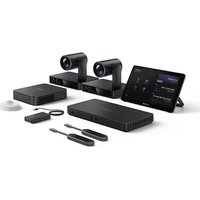
MVC S40 - Video Conferencing System Yealink - Free user manual and instructions
Find the device manual for free MVC S40 Yealink in PDF.


| Product Type | Video Conferencing System |
| Brand | Yealink |
| Model | MVC S40 |
| Dimensions (W x H x D) | Approximately 19.5 x 6.8 x 4.2 inches (495 x 173 x 107 mm) |
| Weight | Approximately 2.5 kg (5.5 lbs) |
| Power Supply | Power over Ethernet (PoE) IEEE 802.3af/at or 12V DC adapter |
| Main Functions | Full HD 1080p video, integrated speakerphone, 360-degree microphone pickup, auto-framing, noise reduction |
| Compatibility | Microsoft Teams, Zoom, Google Meet, and other major UC platforms |
| Ports | 1x USB-C, 1x HDMI (input), 1x RJ45 (PoE), 1x audio line-in/out |
| Camera Field of View | 120° diagonal |
| Microphone Array | 8 built-in MEMS microphones |
| Speaker | 5W full-range speaker |
| Mounting Options | Tabletop or wall mount (bracket included) |
| Operating Temperature | 0°C to 40°C (32°F to 104°F) |
| Maintenance and Cleaning | Wipe with a soft, dry cloth. Do not use liquid cleaners or solvents. |
| Safety Instructions | Keep away from water and excessive heat. Use only approved power sources. |
| Spare Parts and Repairability | No user-serviceable parts inside. Contact Yealink support or authorized service center for repairs. |
| General Information | Designed for small to medium meeting rooms. Includes remote control and cables. |
Frequently Asked Questions - MVC S40 Yealink
User questions about MVC S40 Yealink
0 question about this device. Answer the ones you know or ask your own.
Ask a new question about this device
Download the instructions for your Video Conferencing System in PDF format for free! Find your manual MVC S40 - Yealink and take your electronic device back in hand. On this page are published all the documents necessary for the use of your device. MVC S40 by Yealink.
USER MANUAL MVC S40 Yealink
SmartVision40 Installation and Deployment GuideSmartVisio
Package ContentsPackage Contents

TIPTIP
- We recommend that you use the accessories provided or approved by Yealink. The use of unapproved third-party accessories may result in poor performance.
- Use the Yealink original power adapter to charge the endpoint only. The use of the third-party power adapter may cause damage to the endpoint.

SmartVision 40

VCR20 Remote Control

(2.5 m, 8.20 ft)
USB 3.0 (A - B) Cable

(3.5 m, 11.48 ft)
Power Adapter (48V/0.7A)

Mounting Bracket
φ 6*30 mm, white,
Polyamide

4*30 mm, FAHOZN3+
1/4 inch*12 mm
1/4 inch*13 mm
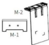
TV-Clip Mount

1/4 inch*8 mm

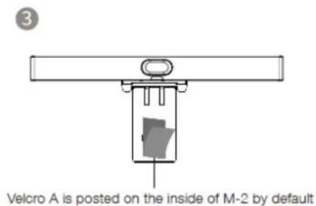
Velcro
(One is on the M-2)
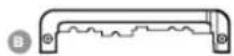

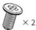
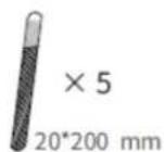

Quick Start Guide
Cable Cover
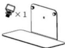
Tabletop Mount (purchase separately)
M2*4 mm, CMH0ZN3+
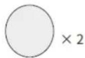
(Φ 38*T1.2 mm)
Silicone Pad
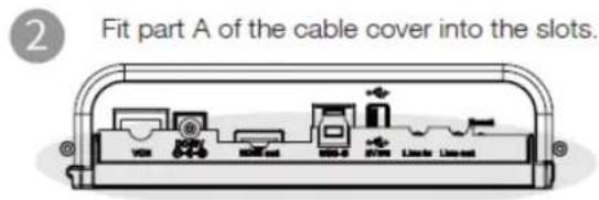
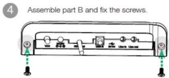
Assemble Cable Cover Assemble Cable Cover
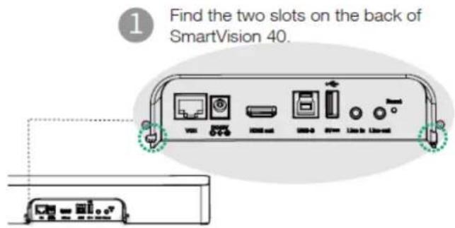
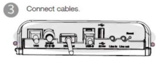

Install SmartVision 40 Install SmartVision 40
Install SmartVision 40 Install SmartVision 40
i NOTENOTE
It is recommended to deploy SmartVision 40 at least 1m from the front row of participants.
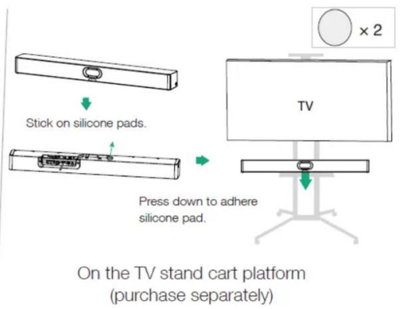
- Put on a Flat SurfacePut on a Flat Surface

On the desk
- Mount on a WallMount on a Wall
Step 1 Step 1: Determine SmartVision 40 position
The mounting height affects your camera view. The recommended height is 110 cm above the ground.
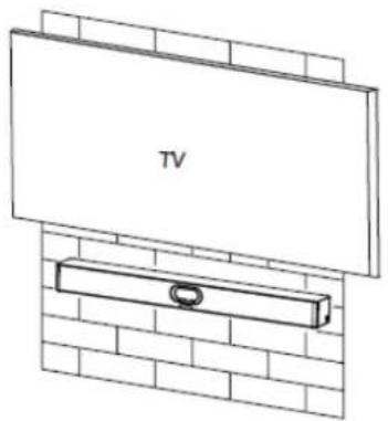
Step 2 Step 2: Mount the SmartVision 40 to the wall

This deployment plan meets the ADA regulatory requirements in the United States.
- Embed in the wallEmbed in the wall
The mounting height affects your camera view. The recommended height is 110 cm above the ground.
i NOTENOTE
- Keep the front of the SmartVision 40 flush with the wall surface.
- The recommended on the left, right, and top sides of the SmartVision 40 is less than 0.5 cm.
- Leave a 5±0.5 cm distance between the back of the SmartVision 40 and the wall surface for cable connections.
- Mount on the Tabletop MountMount on the Tabletop Mount

3

4

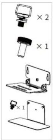
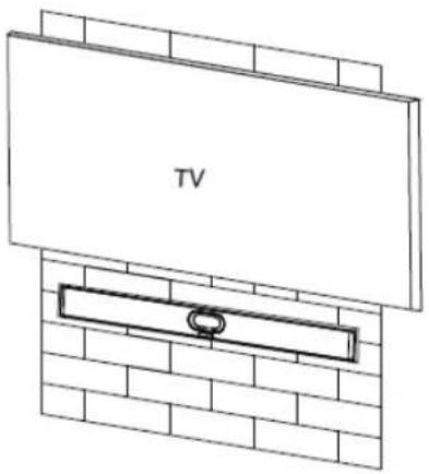
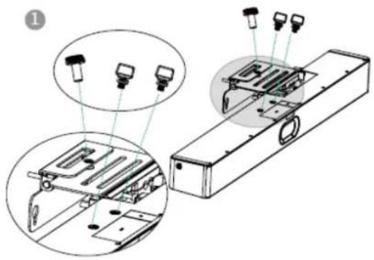
- Mount above a TV or a displayMount above a TV or a display
i NOTENOTE
- The M-2 bracket can be inserted into the M-1 in two directions. Here, we will focus on one direction for illustration.
- Due to device weight, it is advisable to avoid mounting the device on slim TVs to prevent potential falls or damage to the screen.



Adjust Camera TiltAdjust Camera Tilt
![graph TD A["Vehicle Mode ①"] --> B["Position Mode ②"] B --> C["Carved Vehicle Mode ①"] style A fill:#f9f,stroke:#333 style B fill:#bbf,stroke:#333 style C fill:#dfd,stroke:#333 subgraph Position Mode direction LR A1["Left Ellipse ①"] A2["Right Ellipse ②"] end subgraph Visual Scenario direction LR C1…](/content/2026/07/1460478/images/83e238c9d47849cc7cfe4e061414d36bd1bca4c0644e4a995d18da8f8700dd2b.jpg)
Remote Control and Cable Ties Installation Remote Control and Cable Ties Installation
Remote Control Installation

Cable Ties Installation

Hardware Interface Hardware Interface
Please refer to MVC Hardware Overview - SmartVision40 for details.
Connect SmartVision 40Connect SmartVision 40

LED IndicatorLED Indicator
| LED StatusLED Status | DescriptionDescription |
| Off The SmartVision 40 is not properly connected to the mini-PC. | |
| Flashing green There is an incoming call. | |
| Solid green The SmartVision 40 is active. | |
| Solid red The SmartVision 40 is muted. | |
| Solid orange The SmartVision 40 is initializing or in sleep mode. | |
| Flash orange The SmartVision 40 is upgrading firmware. | |
| Flash red and green alternately | The SmartVision 40 is paired with the VCM36-W. |
| Flash red | The SmartVision 40 is in recovery mode, and the firmware has not been upgraded. |

- SMARTVISION40 INSTALLATION AND DEPLOYMENT GUIDESMARTVISIO
- PACKAGE CONTENTSPACKAGE CONTENTS
- TIPTIP
- PUT ON A FLAT SURFACEPUT ON A FLAT SURFACE
- MOUNT ON A WALLMOUNT ON A WALL
- EMBED IN THE WALLEMBED IN THE WALL
- I NOTENOTE
- MOUNT ON THE TABLETOP MOUNTMOUNT ON THE TABLETOP MOUNT
- HARDWARE INTERFACE HARDWARE INTERFACE
Brand : Yealink
Model : MVC S40
Category : Video Conferencing System