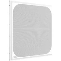
CM50 - Video Conferencing System Yealink - Free user manual and instructions
Find the device manual for free CM50 Yealink in PDF.


| Product Type | Video Conferencing System |
| Brand | Yealink |
| Model | CM50 |
| Dimensions (Microphone Unit) | Approximately 200 × 200 × 50 mm |
| Weight (Microphone Unit) | Approximately 500 g |
| Power Supply | USB-C (5V/2A) or docking station |
| Battery Type | Lithium-ion rechargeable |
| Battery Life | Up to 10 hours of talk time |
| Connectivity | Bluetooth 5.0, USB-C, optional wireless dongle |
| Microphone Type | Omnidirectional with echo cancellation |
| Frequency Response | 100 Hz – 16 kHz |
| Supported Systems | Windows, macOS, Linux, Android, iOS |
| Main Functions | Voice pickup, echo cancellation, noise reduction, mute/unmute |
| Cleaning Instructions | Wipe with a soft dry cloth; avoid liquids and abrasive cleaners |
| Safety Precautions | Do not expose to moisture, extreme temperatures, or direct sunlight |
| Spare Parts Availability | Replacement batteries and charging cables available from authorized dealers |
| Reparability | Battery replaceable by user; other components require professional service |
| Warranty | Standard 2-year limited warranty |
| Package Content | CM50 microphone, base station, USB cable, power adapter (if applicable), quick start guide |
Frequently Asked Questions - CM50 Yealink
User questions about CM50 Yealink
0 question about this device. Answer the ones you know or ask your own.
Ask a new question about this device
Download the instructions for your Video Conferencing System in PDF format for free! Find your manual CM50 - Yealink and take your electronic device back in hand. On this page are published all the documents necessary for the use of your device. CM50 by Yealink.
USER MANUAL CM50 Yealink
You can manage online CM50 devices in Room Designer.
How to Use
On the Room Designer homepage, click Device Manager, where you can perform the following operations.

- Upgrade: Regularly update the device firmware to prevent malfunctions. Firmware download link: Firmware & Tool.
- Set Password: Secure the device settings with a password to prevent others from changing them.
- Export Device Logs: Export the device logs for diagnostic purposes.
- Edit Host Name: Change the device's initial name for easier identification.
- Locate Device: If there are some identical devices in a room, it is difficult to recognize the desired devices. To address this, you can use this feature, and the device you find will flash lights to help you locate the desired device.
-
Device Settings: Perform basic settings, network configurations, and system settings for the device.
-
Add Devices Manually: Manually add the device to the Manager using its IP address.
- Audio Diagnostics: Audio Diagnostics supports on-site packet capture operations for online device nodes, simultaneously storing the captured data and device logs locally in real time.
For detailed introduction on how to operate these features, please refer to the Device Manager for Online Devices.
Create the CM50 Link
Introduction
You can quickly complete the CM50 routing connections using Room Designer. By utilizing the auto-routing feature, you can efficiently build the system and enhance deployment efficiency. With Yealink Room Designer's auto-routing, you can swiftly accomplish the following tasks:
• Automatically create audio signal routes (inputs, outputs, reference signals, etc.)
- Configure signal flow between microphones and audio processors
- Optimize reference signal allocation (AEC REF, AMP REF)
- Rapidly deploy connections between multiple microphones and audio processors
- Visually manage port connection statuses and device parameters
Method 1: With the Auto-Design Wizard
The easiest way to create a room and route devices is by using Room Designer's Auto-Design feature. It automatically routes devices and generates a room layout design based on your needs and the room information you provide.
Method 2: Without the Auto-Design Wizard
If you choose not to use the auto-guide, you can manually route connections. There are two methods for manual routing: you can drag and drop the devices and manually connect them yourself. For more information, please refer to: Link View-View Area or you can use the auto-routing feature. We recommended to use the auto-routing feature, as it simplifies the deployment process and is suitable for engineers of any skill level.
Auto-routing will overwrite any manually created connection paths, so please ensure there are no important custom connections before using it.
Open Yealink Room Designer and navigate to the corresponding room.1.
Under the Design Mode, click Link View.2.
Drag the required audio devices onto the canvas.3.
-
Click Optimize in the top toolbar. Designer will automatically complete the connections between devices, including:
-
Microphone input signals to the audio processor
-
AEC REF and AMP REF signal feedback
-
Connections between output channels and amplifiers/speakers
- Necessary Dante audio channel assignments
After auto-routing, it's recommended to check and fine-tune the configuration:5.
- Remove unnecessary connections to avoid signal redundancy
- Check the levels and gain settings for each channel
- Ensure the AEC echo cancellation reference signal is correctly fed back to the microphone
- Adjust the AP08 matrix mixing settings to ensure correct audio routing
- If there are USB-connected devices, verify their audio output/input connections are correct

Customize Pickup Areas
Introduction
The Yealink CM50 ceiling microphone, designed specifically for versatile meeting scenarios, utilizes beamforming technology. It boasts eight independently operable pickup areas that users can configure using Yealink Room Designer. This allows for the customization of pickup area position, size, and functional attributes to accommodate various complex deployment scenarios.
This article encompasses three pertinent features of the CM50's customized pickup areas:
- Pickup Area: In most scenarios, Yealink recommends using a square-shaped dynamic pickup area to cover all potential speakers in the meeting room. Within the dynamic area, the CM50 will automatically adjust the pickup direction based on the detected sound.
- Pickup Area Priority: The CM50's eight pickup areas correspond to the eight input channels of its built-in automatic mixer. By configuring the pickup area priority attributes, the mixing priority level of a particular pickup area in the automatic mixer can be altered.
- Acoustic Fence: The CM50 actively screens out sounds beyond the pickup area, enhancing the overall conferencing experience.
Customize Pickup Areas
The CM50 offers 8 customized pickup areas, where each area's coverage position can be adjusted within the CM50's pickup range. These areas can be tailored to accommodate different setups by modifying their position and size.
For configuration examples for custom pickup areas, refer to Pickup Areas Best Practices.
Dynamic Pickup Area:
Dynamic Pickup Areas are square-shaped. The CM50 microphone initially identifies the speaker's position and creates a beam within the defined area to capture the sound. If the source is located outside the designated area, no beam is formed.
Dynamic Pickup Areas are suitable for areas with relatively regular shapes and larger sound source areas, or areas where the speaker's position is not fixed, such as stage areas or student areas in classrooms. The following example showcases the application of Dynamic Pickup Areas in a training room with a podium. The two pickup areas cover the podium and the audience area, enabling
separate treatment of the sound captured in these two areas.

Add a Pickup Area
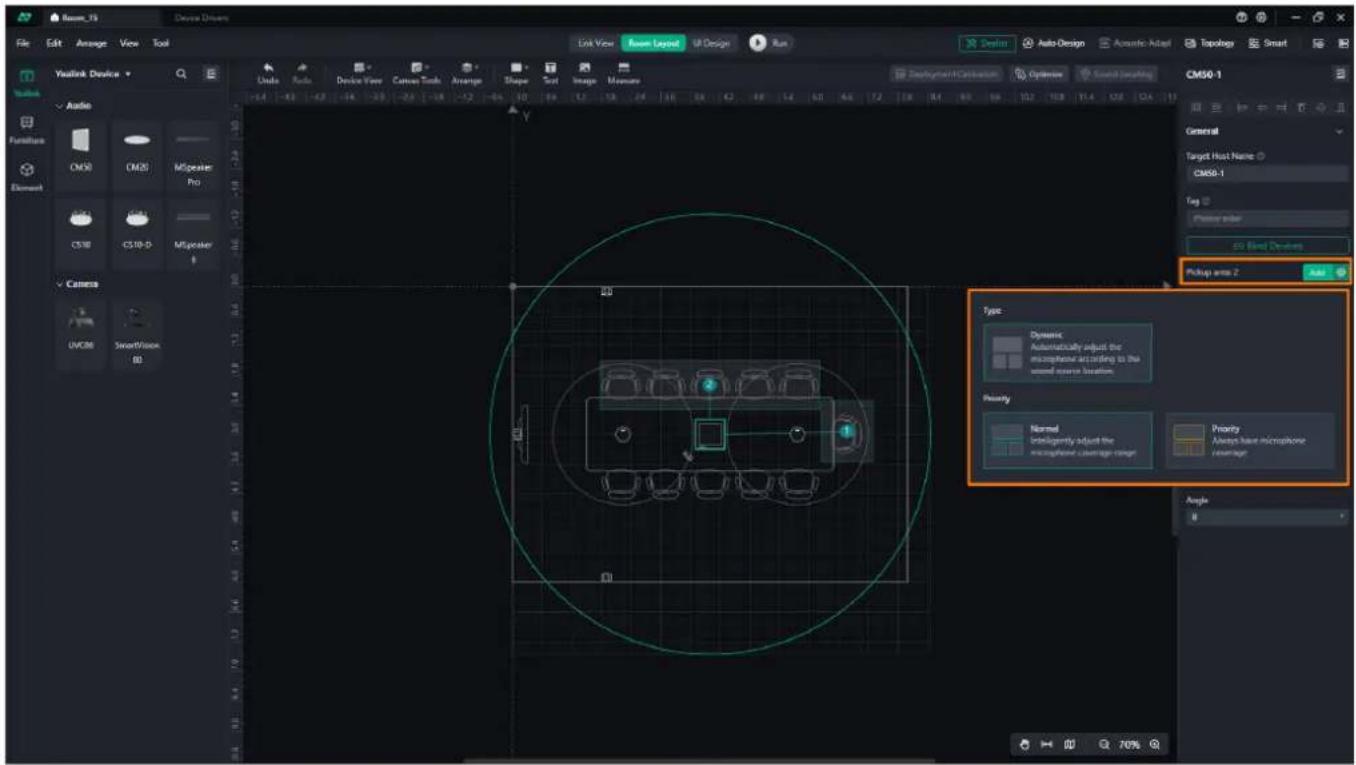
The CM50 has a default pickup area measuring 10m x 10m.
-
Open Yealink Room Designer and navigate to the corresponding room.
-
Under the Design Mode/Run Mode, click Room Layout.
-
Click the desired CM50.
-
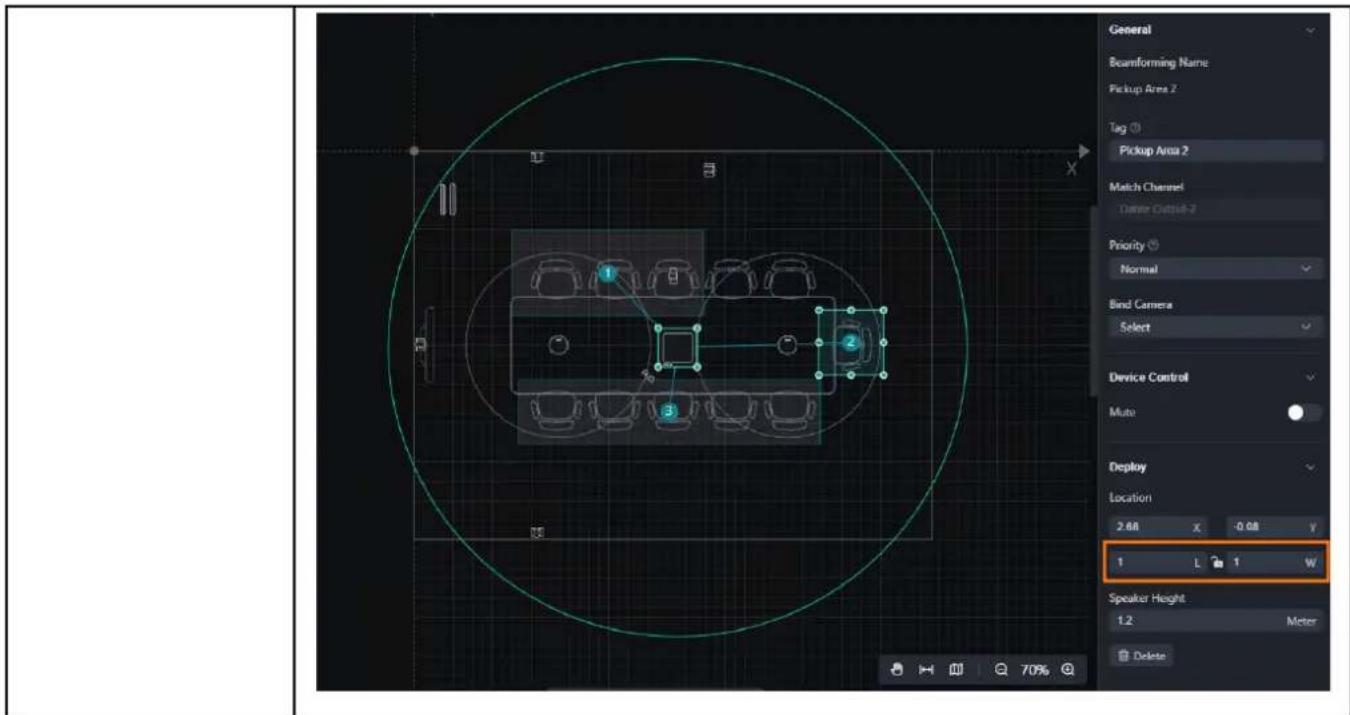
Click Add next to the pickup area field on the right panel to add a pickup area. The default size for a newly added pickup area is 1m x 1m. Pickup areas must not overlap and you can add up to 8 pickup areas per microphone.
Delete a Pickup Area
- Open Yealink Room Designer and navigate to the corresponding room.
- Under the Design Mode/Run Mode, click Room Layout.
-
Do one of the following:
-
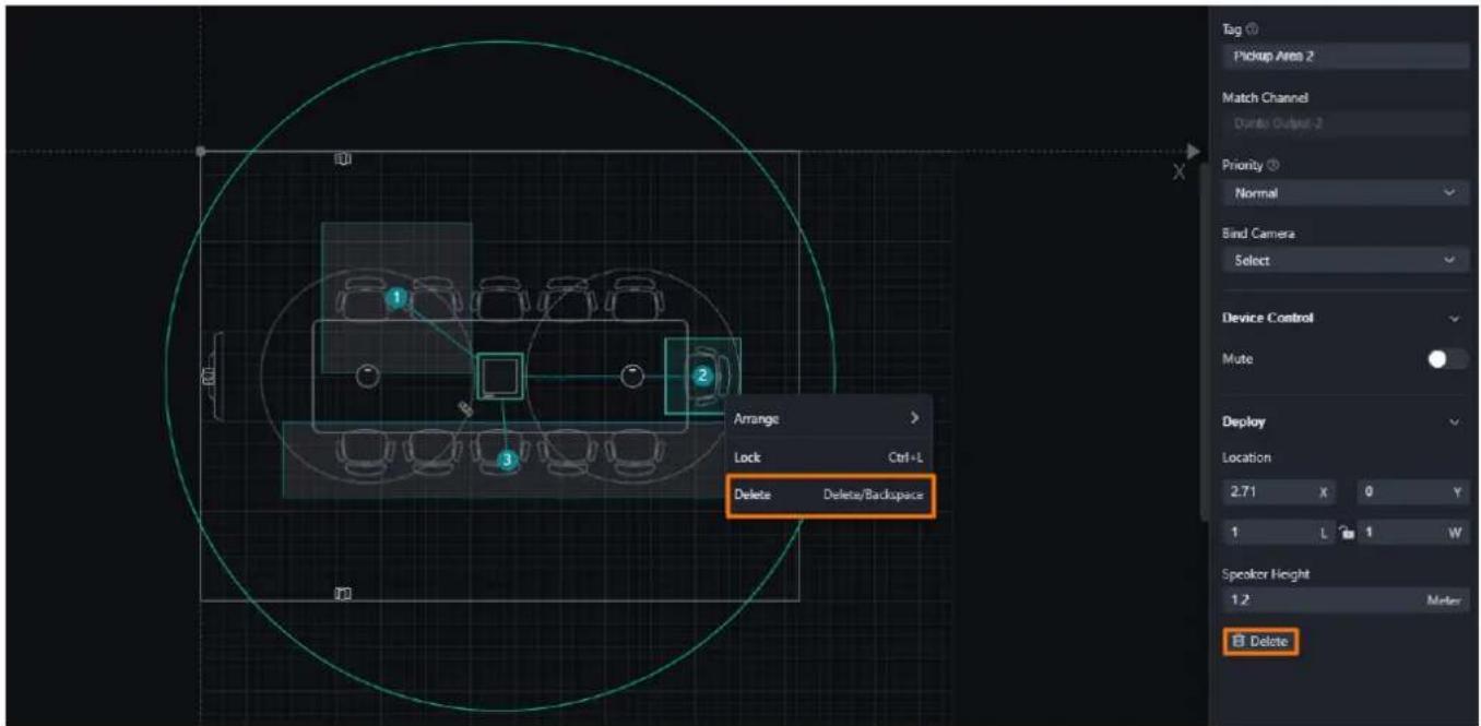
Click the desired pickup area of CM50 and click Delete in the right panel.
- Right-click the desired pickup area and click Delete.
- Click the desired pickup area and press Backspace or Delete.
The last pickup area cannot be deleted.
Move and Resize the Pickup Area
- Open Yealink Room Designer and navigate to the corresponding room.
- Under the Design Mode/Run Mode, click Room Layout.
- Do one of the following:
| Adjustment | Description |
| Move Click the pickup area, hold the left mouse button, and drag the pickup area to the desired position.Click the pickup area and change the X and Y coordinates in the right panel. | 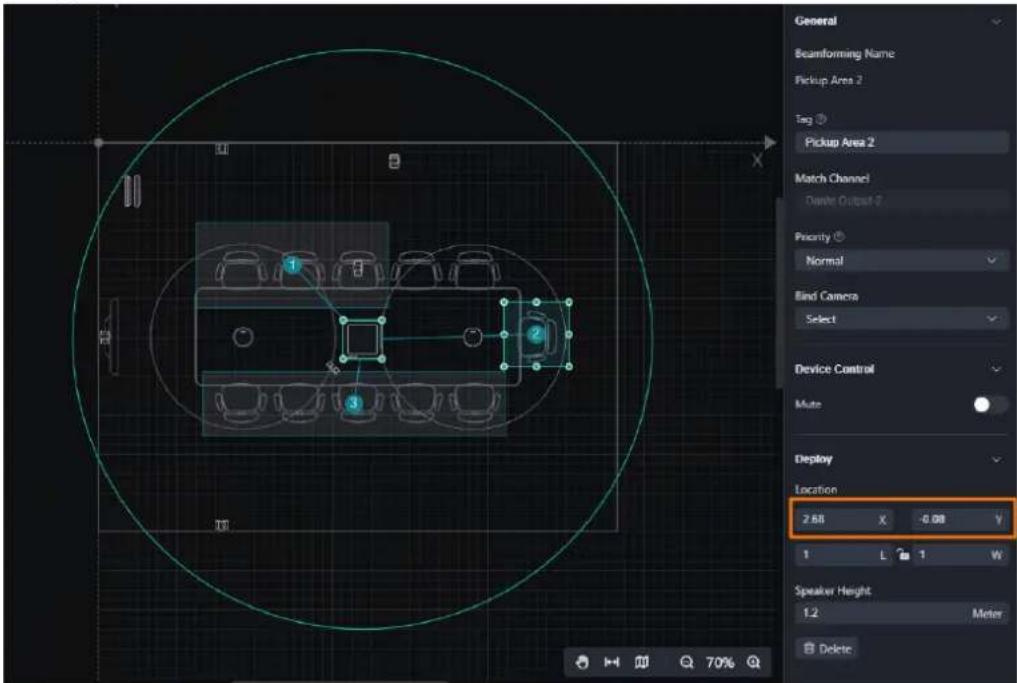 |
| Resize Click the pickup area, hover over the green point until it displays a two-way arrow, and hold the left mouse button to resize the pickup area.Click the pickup area and change the length and width in the right panel.The pickup area must not exceed a rectangular range of 26 m × 26 m. | |
Select Pickup Area Priority
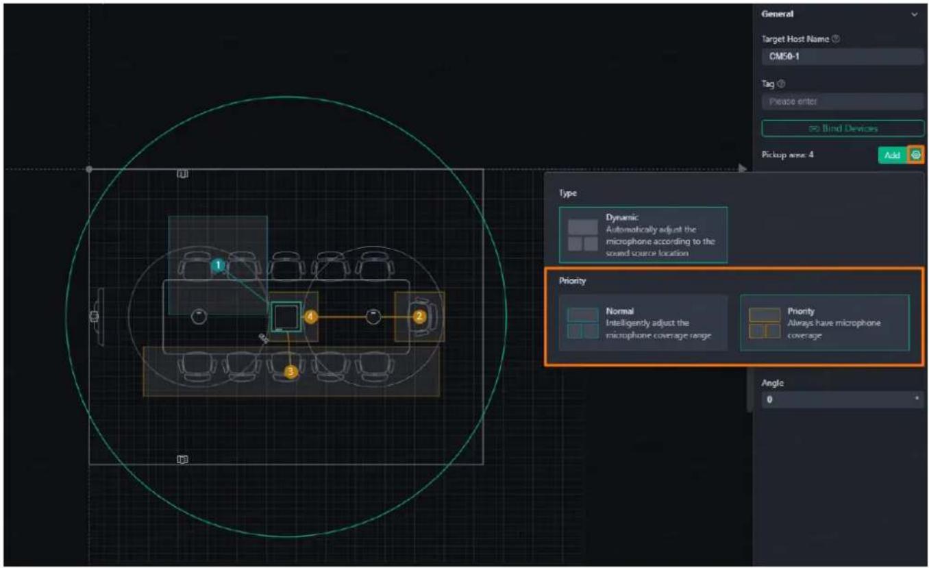
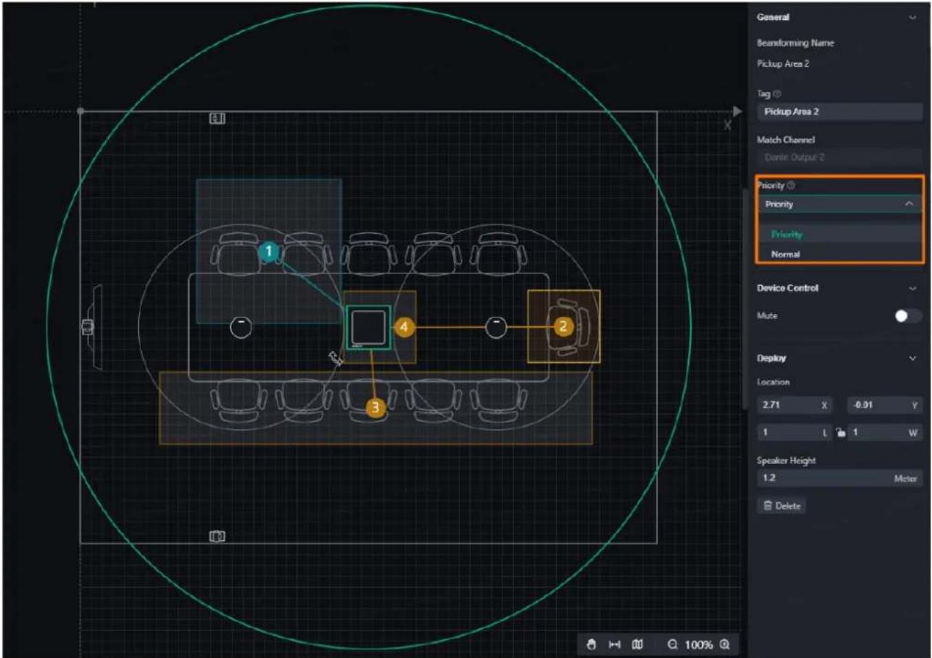
The CM50 microphone offers two priority options for mixing audio from pickup areas:
- Normal: Under ordinary priority, the microphone participates in the mixing process according to the default logic of the automatic mixer.
- Priority: The selected pickup area remains active and has priority in the automatic mixer's mixing process. The priority area is indicated by a yellow color.
We can set commonly used pickup locations or important speaker areas to have priority, ensuring their active participation in the CM50's audio mixing. The following example illustrates a setup scenario in a conference room with a large number of participants, emphasizing the position of the chairperson:
![graph TD A["Room 1"] --> B["Room 2"] A --> C["Room 3"] A --> D["Room 4"] A --> E["Room 5"] A --> F["Room 6"] A --> G["Room 7"] B --> H["Central Square"] C --> H D --> H E --> H F --> H G --> H H --> I["Floor Area"] style H fill:#f9f,stroke:#333,stroke-width:2px](/content/2026/07/1436467/images/13d45bb9bca6e956bb686fbd3b3e2bdadcd54080d3660149de90ca47b8dd22b6.jpg)
Internal Audio Processing Chain of CM50:
The CM50 microphone features a built-in audio processing chain. Each pickup area in the CM50 corresponds to an audio channel in the chain. The CM50 can independently output each channel (pickup area) or mix the sound captured from various areas.
The diagram below illustrates the audio processing chain of the Yealink CM50, with each pickup area represented within a designated box:
![graph TD A["1 Pickup Area 1"] --> B["AGC"] C["2 Pickup Area 2"] --> D["AGC"] E["3 Pickup Area 3"] --> F["AGC"] G["4 Pickup Area 4"] --> H["AGC"] I["5 Pickup Area 5"] --> J["AGC"] K["6 Pickup Area 6"] --> L["AGC"] M["7 Pickup Area 7"] --> N["AGC"] O["8 Pickup Area 8"] --> P["AGC"] Q["9 AEC Reference"…](/content/2026/07/1436467/images/8e8fde9b0c5bc5303188994ab719fae6e1abbe248ffdf1a721a77028f85b24b8.jpg)
- Each pickup area can be individually outputted via Dante, and each output channel can utilize AGC to limit the output signal level.
- After the automatic mixing of all pickup areas, the resulting audio signal undergoes processing by the CM50's built-in AEC (Acoustic Echo Cancellation) and Yealink's AI noise cancellation algorithm for sound optimization. This processing chain allows for PEQ
(Parametric Equalization) treatment of the mixed sound and provides options for AGC, Delay, and other signal restrictions.
CM50 Automixer:
The CM50 can mix the audio from eight pickup areas before outputting the final sound. Users have the flexibility to choose which pickup areas participate in the mix and can set the priority status for each pickup area's channel during the mixing process. The resulting mixed signal can undergo further processing using the CM50's built-in algorithms for AEC, noise reduction, and reverberation elimination.

Open Yealink Room Designer and navigate to the corresponding room.1.
- Under the Design Mode/Run Mode, use one of the following methods to set the priority of pickup areas:
- Before adding a pickup area, click Room Layout, select the CM50 and click the

icon next to Pickup Areas. Set the priority for each pickup area.
- Click Room Layout, click the CM50 and select the desired pickup area. Set the priority in the right panel.
- Under Link View/Room Layout, double-click the CM50 to access the audio processing chain,
and then click Automixer. Turn on Always and Priority for the desired pickup area.

Due to system limitations, after configuring the Automixer, the status won't update in the Room Layout in real-time. Switching to Link View and then back to Room Layout will resolve this issue.

Acoustic Fence
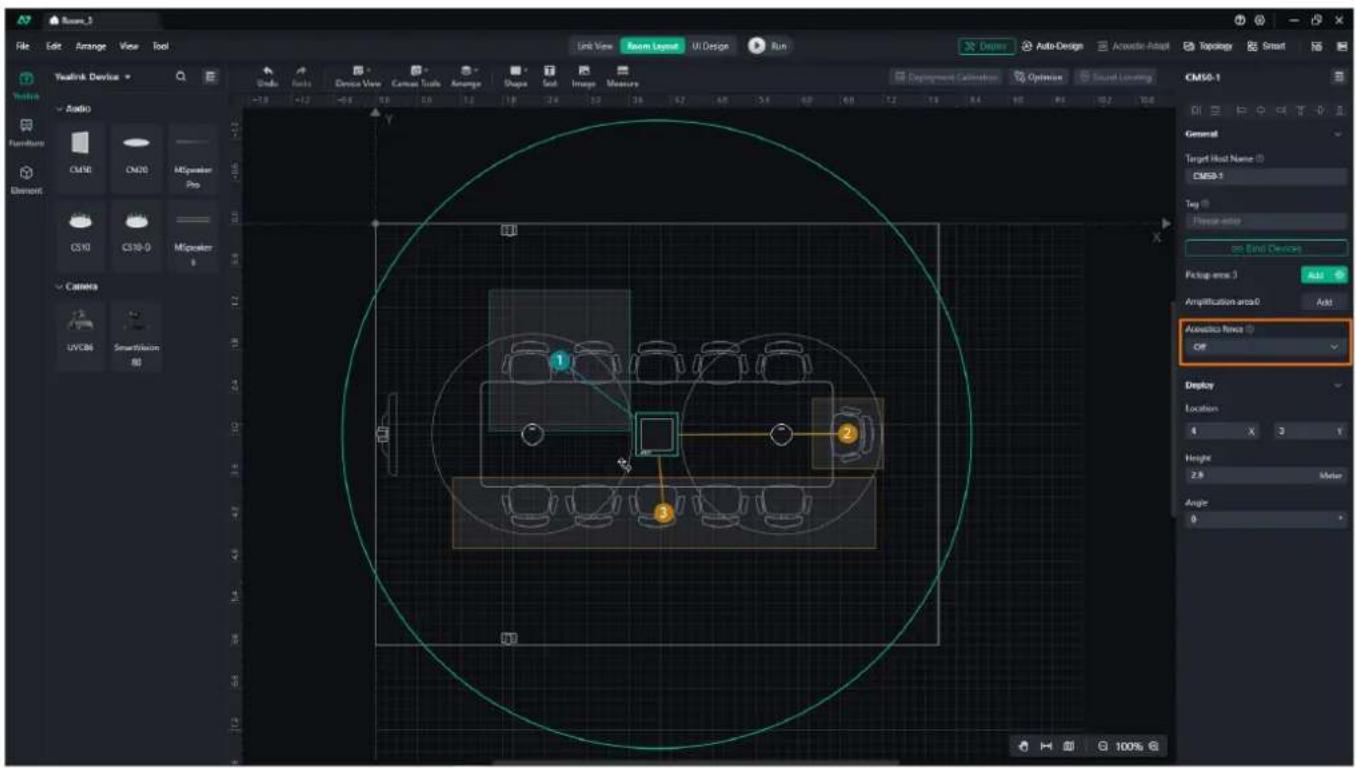
The CM50 is capable of actively blocking out sound outside the pickup areas, enhancing the conference call experience.
Application Scenarios
It is recommended to enable the CM50 acoustic fence feature in the following scenarios to achieve a pristine sound experience:
- In the presence of stable noise sources, such as air conditioning units or equipment cabinets.
- When there is a need to prevent sound from outside the conference area from being picked up, such as in open space meetings or rooms with poor sound insulation.
Open Yealink Room Designer and navigate to the corresponding room.1.
- Under Design Mode/Run Mode, click Room Layout.
- Select CM50 and click the dropdown menu of Acoustic Fence and select on/off.
Case
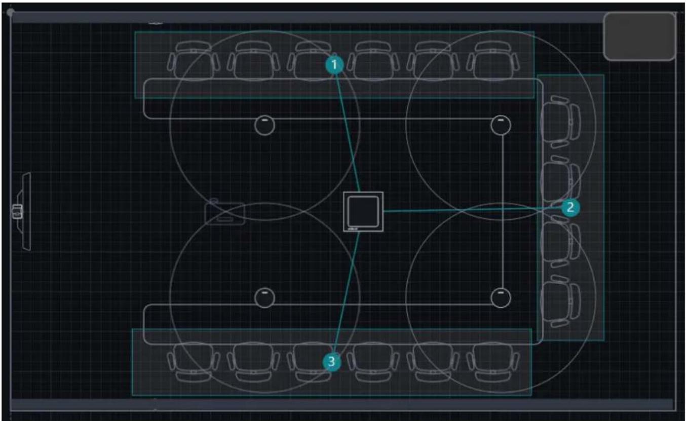
In the following case, the center area on the left side of the room has a projector, the top and bottom sides have air conditioning vents, and the top right corner houses a cabinet with conference equipment. These areas all generate stable and continuous noise interference.
Therefore, when setting up the pickup area, we configure it as follows to ensure that all seats are covered and all noise-generating areas are located outside the pickup area. At this point, enabling the sound masking function will provide a cleaner conference call experience.
CM50 Audio Processing Configuration
Introduction
This chapter introduces the audio parameters of the CM50 that can be adjusted in Designer and explains how to make these adjustments.
How to Use
Under the Design Mode/Run Mode, double-click the CM50 to go to the page to set the device's acoustic parameters.
Acoustic Parameters
Audio Flow displays the entire audio signal chain of the device, allowing you to adjust settings and monitor signals. Double-click a specific module to adjust audio parameters or access the console.
![graph TD A["1 Pickup Area 1"] --> B["AGC"] C["2 Pickup Area 2"] --> D["AGC"] E["3 Pickup Area 3"] --> F["AGC"] G["4 Pickup Area 4"] --> H["AGC"] I["5 Pickup Area 5"] --> J["AGC"] K["6 Pickup Area 6"] --> L["AGC"] M["7 Pickup Area 7"] --> N["AGC"] O["8 Pickup Area 8"] --> P["AGC"] Q["Automaker"] -->…](/content/2026/07/1436467/images/0a8a8528f0c99230cea4efd1b44c71d091ddab8fb2d772da954860cf0952098d.jpg)
The adjustable parameters supported by the CM50 are shown in the table below.
| Module Description | |
| Pickup Area The zone where the device can effectively pick up sound signals.Please refer to:Acoustic Components. | |
| Amplifier Area The zone | where audio signals are amplified.Please refer to:Acoustic Components. |
| Automixer An automixer | is a tool used to automatically adjust the volume balance of multiple audio signals.Please refer to:Acoustic Components. |
| Mic AEC Technology that | reduces or eliminates echoes caused by sound reflections in the acoustic environment when using a microphone improves the clarity of the audio signal.Please refer to:Acoustic Components. |
| PEQ (Parametric Equalizer) | The Parametric Equalizer (PEQ) allows users to maximize audio quality by adjusting the frequency response of an audio signal across specific frequency ranges according to their needs.Please refer to:Acoustic Components. |
| AGC (Automatic Gain Control) | The Automatic Gain Control (AGC) block maintains a consistent volume level for all speakers in various situations.Please refer to:Acoustic Components. |
| Delay The Delay block is | used to introduce a time delay to an audio signal.Please refer to:Acoustic Components. |
| AFC (Adaptive Feedback Cancellation) | Adapts to and cancels out feedback signals that can cause howling or unwanted noise in audio systems.Please refer to:Acoustic Components. |
| Dante Output Outputs | audio signals in the Dante protocol format.Please refer to:Acoustic Components. |
| Dante Output-Mix Out | outputs a mixed audio signal in the Dante protocol format.Please refer to:Acoustic Components. |
| Analog Output-Mix Out | Outputs a mixed audio signal in analog format.Please refer to:Acoustic Components. |
| Local Amplification Out | Provides an output for local amplification.Please refer to:Acoustic Components. |
Acoustic Fence
The CM50 is capable of actively blocking out sound outside the pickup areas,
enhancing the conference call experience. For details, please refer to CM50
Acoustic Fence.
- Click Acoustic Fence in the upper right corner of the toolbar to turn this feature on or off.
![graph TD A["1 Pickup Area 1"] --> B["ACC"] C["2 Pickup Area 2"] --> D["AGC"] E["3 Pickup Area 3"] --> F["AGC"] G["4 Pickup Area 4"] --> H["AGC"] I["5 Pickup Area 5"] --> J["AGC"] K["6 Pickup Area 6"] --> L["AGC"] M["7 Pickup Area 7"] --> N["AGC"] O["8 Pickup Area 8"] --> P["AGC"] Q["Automotive"] -->…](/content/2026/07/1436467/images/ef46df19bee225bfdc01777ac7e288a0e39064a5e59a79bb7ce82af5733372a4.jpg)
Other Settings
For information on how to use other general settings, please refer to: General Settings.
Preset
Introduction
Yealink CM50 preset is used to save the current parameter settings and pickup area configurations in the CM50 audio chain. For more information on how to use the preset, refer to Preset.
How to Use
- Under the Link View/Room Layout, double-click the CM50 to go to the Audio Flow.
- Click Preset in the upper right to add a preset. When no components are selected, save all. If specific components are selected, save only those.
![graph TD A["1 Pickup Area 1"] --> B["AGC"] C["2 Pickup Area 2"] --> D["AGC"] E["3 Pickup Area 3"] --> F["AGC"] G["4 Pickup Area 4"] --> H["AGC"] I["5 Pickup Area 5"] --> J["AGC"] K["6 Pickup Area 6"] --> L["AGC"] M["7 Pickup Area 7"] --> N["AGC"] O["8 Pickup Area 8"] --> P["AGC"] Q["9 AEC Reference"…](/content/2026/07/1436467/images/58a1633121ef12fa2b933faed914bc768bcd85c40fe3ed35d2f01a059d0bbfad.jpg)
Mute Sync
Introduction
It's important to be able to see if a room is muted or unmuted during a call. You want devices to show the same mute status as the videoconferencing software.
How to Use
When mute sync is working correctly, you can mute the videoconferencing software to mute the room. If you mute the call, the LED Indicator of the CM50 glows red. If you unmute the call, the LED Indicator glows green.
![graph LR A["CM50"] --> B["AP08"] B --> C["Mini PC/PC with Conferencing software"] style A fill:#f9f,stroke:#333 style B fill:#ccf,stroke:#333 style C fill:#cfc,stroke:#333](/content/2026/07/1436467/images/9b4eb77124d397d3d4c484c514047227181b10a44520972fc7bef99950dbd8db.jpg)

- HOW TO USE
- CREATE THE CM50 LINK
- INTRODUCTION
- METHOD 1: WITH THE AUTO-DESIGN WIZARD
- METHOD 2: WITHOUT THE AUTO-DESIGN WIZARD
- CUSTOMIZE PICKUP AREAS
- DYNAMIC PICKUP AREA
- DELETE A PICKUP AREA
- MOVE AND RESIZE THE PICKUP AREA
- SELECT PICKUP AREA PRIORITY
- INTERNAL AUDIO PROCESSING CHAIN OF CM50
- CM50 AUTOMIXER
- ACOUSTIC FENCE
- APPLICATION SCENARIOS
- CASE
- CM50 AUDIO PROCESSING CONFIGURATION
- OTHER SETTINGS
- PRESET
- MUTE SYNC
Brand : Yealink
Model : CM50
Category : Video Conferencing System