AT-AVA-EX70C-BP-KIT - Audio/video extender Atlona - Free user manual and instructions
Find the device manual for free AT-AVA-EX70C-BP-KIT Atlona in PDF.


| Product Type | 4K/UHD HDMI Extender Kit with Control and Bidirectional Remote Power |
| Brand | Atlona |
| Model | AT-AVA-EX70C-BP-KIT |
| Max Video Resolution | 4K/UHD 60Hz 4:2:0 up to 130 ft (40 m); 1080P 60Hz up to 230 ft (70 m) |
| Audio Support | Multi-channel audio over HDMI; ARC available on HDMI connections |
| Control Interface | RS-232 and IR pass-through (bidirectional) |
| Power Supply | 48V DC, 1 power supply included; supports bidirectional remote powering (TX or RX) |
| Transmission Cable | Single CAT6A/7 (recommended); also compatible with CAT5e/6 |
| Maximum Distance (4K) | 130 ft (40 m) with CAT6a/7; 115 ft (35 m) with CAT5e/6 |
| Maximum Distance (1080p) | 230 ft (70 m) with CAT6a/7; 200 ft (60 m) with CAT5e/6 |
| Ports (Transmitter) | HDMI IN, HDBaseT OUT, DC 48V, RS-232, IR IN, IR OUT, FW (micro-USB for firmware update) |
| Ports (Receiver) | HDMI OUT, HDBaseT IN, DC 48V, RS-232, IR IN, IR OUT |
| Built-in HDBaseT Test | Front panel TEST button and LED for cable quality check |
| Included Accessories | TX, RX, 2-pin, 3-pin, 4-pin, 5-pin captive screw connectors, IR emitter, 4 mounting brackets, 8 mounting screws, 48V DC power supply, IEC cable, Installation Guide |
| Mounting | Surface mount with included brackets; can be inverted for under-table mounting |
| Firmware Update | Via micro-USB on transmitter; receiver updated automatically when connected |
| Warranty | See https://atlona.com/warranty/ |
Frequently Asked Questions - AT-AVA-EX70C-BP-KIT Atlona
User questions about AT-AVA-EX70C-BP-KIT Atlona
0 question about this device. Answer the ones you know or ask your own.
Ask a new question about this device
Download the instructions for your Audio/video extender in PDF format for free! Find your manual AT-AVA-EX70C-BP-KIT - Atlona and take your electronic device back in hand. On this page are published all the documents necessary for the use of your device. AT-AVA-EX70C-BP-KIT by Atlona.
USER MANUAL AT-AVA-EX70C-BP-KIT Atlona
4K/UHD HDMI Extender Kit with Control and Bidirectional Remote Power
AT-AVA-EX70C-BP-KIT
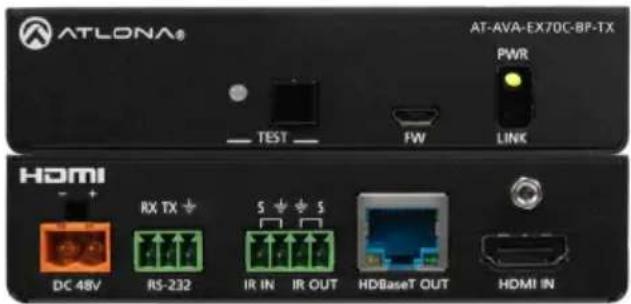
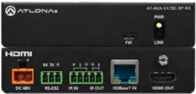
The Atlona AT-AVA-EX70C-BP-KIT is an Avance™ Series HDBaseT transmitter and receiver set that supports control pass-through and bidirectional remote power capabilities. The kit transmits 4K/UHD 60Hz 4:2:0 video up to 130 feet (40 meters) or 1080P 60Hz video up to 230 feet (70 meters). In addition to video with embedded multi-channel audio, RS-232 and IR control signals, and remote powering by either the transmitter or the receiver are supported on the single CAT6A/7 cable. Integrated HDBaseT link status testing allows quick verification of cable, termination, and link quality. HDMI clock stretching and EDID filtering are included to ensure the integrity of video transmission as well as compatibility with the widest array of sources and display devices. ARC is available on the HDMI connections to minimize cabling in audio return applications. Compact enclosures and included brackets allow the transmitter and receiver endpoints to be surface mounted in furniture or behind a display. The AT-AVA-EX70C-BP-KIT delivers a cost-effective solution for extension of video, audio, control, and bidirectional power at resolutions up to 4K/UHD.
Package Contents
1 x AT-AVA-EX70C-BP-TX
1 x AT-AVA-EX70C-BP-RX
1 x 2-pin captive screw connector
2 x 3-pin captive screw connector
1 x 4-pin captive screw connector
1 x 5-pin captive screw connector
1 x IR emitter
4 x Mounting brackets
8 x Mounting screws
1 x 48V DC power supply
1 x IEC cable
1 x Installation Guide

IMPORTANT: Visit https://atlona.com/product/AT-AVA-EX70C-BP-KIT for the latest firmware updates and Installation Guide.
Panel Descriptions
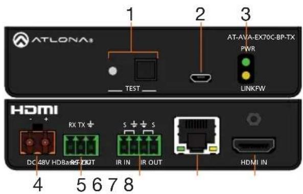
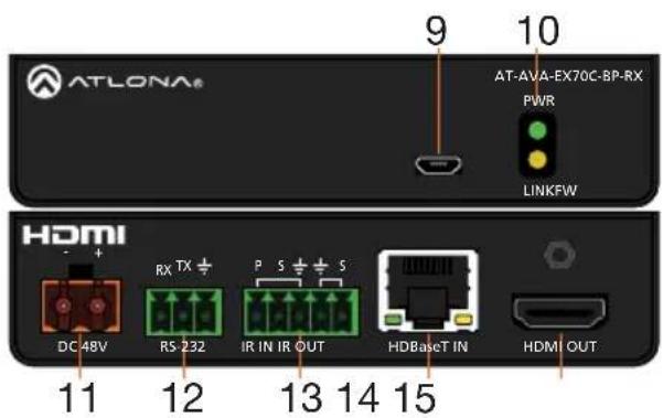
1 TEST
Quick and easy test for category cables. Use the button to start the test and the LED to determine pass or fail.
2 FW
Connect a micro-USB to USB-A type cable from this port to a computer, to update the firmware.
3 POWER and LINK LEDs
The power LED will illuminate green when receiving power. The link LED will glow yellow when signal is being sent/received between the transmitter and the receiver.
4 DC 48V \*Optional\*
Connect the included power supply to either this port or the power port on the receiver.
5 RS-232
Bidirectional control port, used for pass through of commands to or from the receiver.
6 IR IN/OUT
Connect a 3rd party controller to the IR IN port or an IR emitter to the IR OUT port.
7 HDBaseT OUT
Connect an HDBaseT cable from this port to the HDBaseT IN port on the receiver.
8 HDMI IN
Connect an HDMI cable from a source to this port. e.g. HDR BluRay Player
9 FW
Not used at this time.
10 POWER and LINK LEDs
The power LED will illuminate green when receiving power. The link LED will glow yellow when signal is being sent/received between the transmitter and the receiver.
11 DC 48V \*Optional\*
Connect the included power supply to either this port or the power port on the transmitter.
12 RS-232
Bidirectional control port, used for pass through of commands to or from the transmitter.
13 IR IN/OUT
Connect an IR receiver to the IR IN port or an IR emitter to the IR OUT port.
14 HDBaseT IN
Connect an HDBaseT cable from this port to the HDBaseT OUT port on the transmitter.
15 HDMI OUT
Connect an HDMI cable from this port to an HDMI display.
HDBaseT LED Descriptions
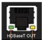
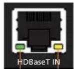
b ba a
a Green LED
When a category cable is connected and receiving signal this LED will be illuminated. If no cable or signal is being received, the LED will be off.
b Yellow LED
This LED displays the status of the HDBaseT firmware. When the LED is blinking slowly, the firmware is good. If the LED is blinking rapidly or off, there is no firmware or the firmware has been corrupted.
RS-232
A 3-pin captive screw connector for RS-232 has been included.

natural_image
Green 3D model of a mechanical connector or terminal block (no text or symbols visible)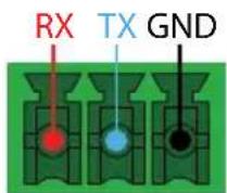
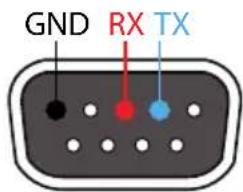
Pin out will be determined by the RS-232 cable and connect as RX (receive), TX (transmit) and ± (Ground).
IR
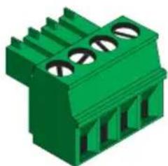
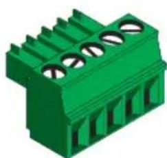
Two captive screw connectors for IR have been included. A 4-pin connector for the transmitter and a 3-pin connector for the receiver.
natural_image
Green 3D component with three circular holes, no text or symbols visible
IR IN is connected by a ground and signal wire. Use with 3rd party control systems. For easy termination, Atlona recommends using the 2 meter IR cable AT-LC-CS-IR-2M (purchasable through atlona.com).
IR OUT is connected by a ground and signal wire. Use the included IR emitter with this port.
natural_image
Green 3D component with three circular slots, no visible text or symbols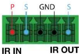
IR IN is connected by a power, ground, and signal wire. Use a 12V IR receiver with it (e.g. AT-IR-CS-RX purchasable through atlona.com).
IR OUT is connected by a ground and signal wire. Use the included IR emitter with this port.
Power
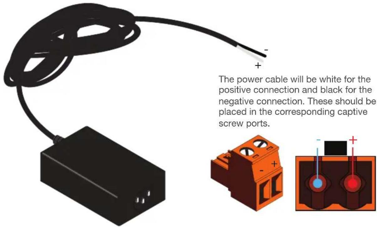
A 2-pin captive screw connector for the power supply has been included.
Mounting Instructions
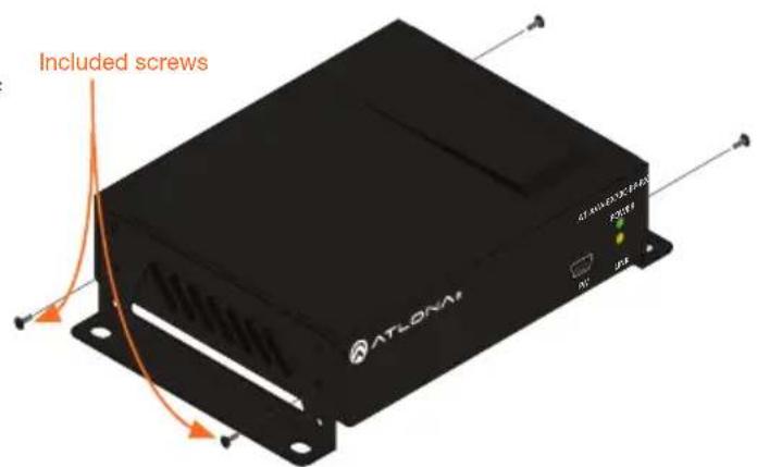
The AT-AVA-EX70C-BP-KIT includes two mounting brackets and four mounting screws each, which can be used to attach the units to any flat surface.
-
Position one of the mounting brackets, as shown below, aligning the holes on the side of the enclosure with one set of holes on the mounting bracket.
-
Use the enclosure screws to secure the mounting bracket to the enclosure.
-
Repeat the above steps to attach the second mounting bracket to the opposite side of the unit.
-
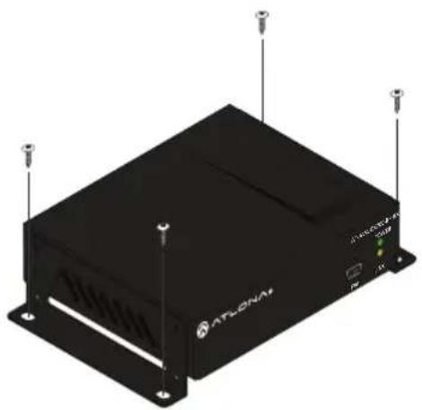
Mount the unit using the oval-shaped holes, on each mounting bracket. If using a drywall surface, a #6 drywall screw is recommended.

NOTE: Mounting brackets can also be inverted to mount the unit under a table or other flat surface.
natural_image
Exterior view of a black ATLONAV device with ventilation grilles and antenna (no visible text or symbols)Installation
- Connect a source to the HDMI IN port on the transmitter.
- Connect a display to the HDMI OUT port on the receiver.
- Connect an HDBaseT cable, from the HDBaseT OUT port on the transmitter, to the HDBaseT IN port on the receiver.
- *Optional* Connect a 3rd party controller to the transmitter using either the 3-pin RS-232 or the 2-pin IR IN ports.
- *Optional* Connect an IR receiver to the IR IN port of the receiver.
- *Optional* Connect an IR emitter to the IR OUT port of the transmitter or receiver.
- Connect the included 48V power supply into the transmitter or receiver.
- Connect power supply to an AC outlet.
Cable Recommendation Guidelines
Refer to the tables below for recommended cabling when using Altona products with HDBaseT. The green bars indicate the signal quality when using each type of cable. Higher-quality signals are represented by more bars.
| Core | Shielding | CAT5e | CAT6 | CAT6a | CAT7 |
| Solid UTP (unshielded) N/A | |||||
| STP (shielded) | |||||
| Performance Rating (MHz) | 350 | 500 | 600 | 800 | |

IMPORTANT: It is recommended to use UTP6A (https://atlona.com/product/utp6a/) and STP6X (https://atlona.com/product/stp6x/) if a stranded/patch cable is needed. These cables have been tested and approved to work with these extenders for full functionality.
| Cable* | Max. Distance @ 4K | Max. Distance @ 1080p |
| CAT5e/6 | 115 feet (35 meters) | 200 feet (60 meters) |
| CAT6a/7 | 130 feet (40 meters) | 230 feet (70 meters) |
*Atlona recommends TIA/EIA 568-B termination for optimal performance.
TEST
The transmitter has the ability to test the HDBaseT cable quality through the front panel. Press the test button on the front panel of the transmitter to start the test, the LED will display the testing results.
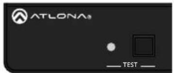

Button:
- Blue Blinking: The test is running properly and the button will blink 10 times during the testing process.
- Red Light: There is no signal for the test to check.
LED:
- No Light: There is no HDBaseT cable plugged in.
- Blinking: There is no HDBaseT signal coming through.
• Solid Green: The HDBaseT cable is good. - Solid Yellow: One or two HDBaseT pairs are not working, reterminate the cable.
- Solid Red: Multiple pairs are not working. Reterminate the cable and if the LED turns yellow or red again, replace the cable.
Updating Firmware
- Download the firmware .zip file from the firmware tab located at https://atlona.com/product/AT-AVA-EX70C-BP-KIT.
- Unzip the .bin file to an easy to locate area of the local PC.
- Connect the transmitter's FW micro USB port to a PC using a micro USB to USB A cable (purchased separately).
- The PC should automatically detect the unit and display the autorun options. Select the view files in folder option. A new window will open.
- If there are any files inside the folder, delete them, otherwise drag and drop the .bin file into the folder. While the firmware loads to the unit, the green power LED on the front panel will flash. This process can take up to 5 minutes to complete.
- Once the green LED goes solid, disconnect the unit from the PC. The firmware update is finished.

NOTE: Only the transmitter will be used for updating firmware. The receiver will be updated once it has been connected to the transmitter if it is not connected at the time of the firmware update.
Warranty
To view the product warranty, use the following link or QR code: https://atlona.com/warranty/.

Version 3
English Declaration of Conformity
The English version can be found under the resources tab at: https://atlona.com/product/at-ava-ex70c-bp-kit/.

Chinese Declaration of Conformity 中国RoHS合格声明
由SKU列出於:
https://atlona.com/about-us/china-rohs/.


HIGH-DEFINITION MULTIMEDIA INTERFACE
The terms HDMI, HDMI High-Definition Multimedia Interface, and the HDMI Logo are trademarks or registered trademarks of HDMI licensing Administrator, Inc.

ATLONA.
a Payout company
US International
atlona.com • 408.962.0515 • 41.43.508.4321
25147-R3
© 2024 Atlona Inc. All rights reserved. "Atlona" and the Atlona logo are registered trademarks of Atlona Inc. All other brand names and trademarks or registered trademarks are the property of their respective owners. Pricing, specifications and availability subject to change without notice. Actual products, product images, and online product images may vary from images shown here.
- 4K/UHD HDMI Extender Kit with Control and Bidirectional Remote Power
- Package Contents
- TEST
- FW
- POWER and LINK LEDs
- DC 48V \*Optional\*
- RS-232
- IR IN/OUT
- HDBaseT OUT
- HDMI IN
- FW
- POWER and LINK LEDs
- DC 48V \*Optional\*
- RS-232
- IR IN/OUT
- HDBaseT IN
- HDMI OUT
- HDBaseT LED Descriptions
- a Green LED
- b Yellow LED
- RS-232
- IR
- Power
- Mounting Instructions
- Installation
- Cable Recommendation Guidelines
- TEST
- Button:
- LED:
- Updating Firmware
- Warranty
- English Declaration of Conformity
- Chinese Declaration of Conformity 中国RoHS合格声明
Brand : Atlona
Model : AT-AVA-EX70C-BP-KIT
Category : Audio/video extender