AT-OME-EX-WP-KIT-LT - Audio/video extender Atlona - Free user manual and instructions
Find the device manual for free AT-OME-EX-WP-KIT-LT Atlona in PDF.


| Product Type | HDBaseT Audio/Video Extender Kit |
| Model | AT-OME-EX-WP-KIT-LT |
| Brand | Atlona |
| Video Resolution Support | Up to 4K/UHD at 60 Hz (4:2:0); 1080p at 60 Hz |
| Maximum Distance (4K) | 130 ft (40 m) with CAT6a/7; 115 ft (35 m) with CAT5e/6 |
| Maximum Distance (1080p) | 230 ft (70 m) with CAT6a/7; 200 ft (60 m) with CAT5e/6 |
| HDCP | HDCP 2.2 compliant |
| USB Extension | USB 2.0 host and device ports |
| Control Extension | RS-232 pass-through; IR pass-through (via HDBaseT) |
| Transmitter Form Factor | US 1-gang wallplate (interchangeable black/white faceplates and wallplates) |
| Receiver Form Factor | Compact box with mounting brackets |
| Power Supply | 48 V DC, 2-pin captive screw connector (included) |
| Power Delivery | PoC (Power over HDBaseT) to transmitter |
| USB Port Power | 2.5 W per USB port (transmitter device port; receiver device ports) |
| LED Indicators | PWR (green) and LINK (amber/yellow) on both units |
| Mounting | Transmitter: standard US electrical box; Receiver: included mounting brackets |
| Operating Temperature | 32 °F to 104 °F (0 °C to 40 °C) |
| Storage Temperature | -4 °F to 140 °F (-20 °C to 60 °C) |
| Package Contents | Transmitter, receiver, faceplates (2 colors), wallplates (2 colors), RS-232 covers, mounting screws, captive screw connectors, power supply, installation guide |
| Warranty | See https://atlona.com/warranty/ |
Frequently Asked Questions - AT-OME-EX-WP-KIT-LT Atlona
User questions about AT-OME-EX-WP-KIT-LT Atlona
0 question about this device. Answer the ones you know or ask your own.
Ask a new question about this device
Download the instructions for your Audio/video extender in PDF format for free! Find your manual AT-OME-EX-WP-KIT-LT - Atlona and take your electronic device back in hand. On this page are published all the documents necessary for the use of your device. AT-OME-EX-WP-KIT-LT by Atlona.
USER MANUAL AT-OME-EX-WP-KIT-LT Atlona
The Atlona AT-OME-EX-WP-KIT-LT is an HDBaseT extender for video up to 4K/60 4:2:0, plus embedded audio, control, and USB over distances up to 130 feet (40 meters) for 4K/UHD, and up to 230 feet (70 meters) for 1080p/60 video. The transmitter features a US one-gang, wallplate form factor, and includes interchangeable black and white wallplates and faceplates. Part of the Omega™ Series of integration products for modern AV communications and collaboration, the OME-EX-WP-KIT-LT is HDCP 2.2 compliant and extends RS-232 control signals. The integrated USB extension addresses the challenge of connecting between USB devices at remote locations, and is ideal for software video conferencing and touch or interactive displays. The transmitter includes a USB 2.0 host interface for a PC, plus a peripheral device such as a speakerphone, microphone, or keyboard and mouse. The receiver provides two USB interfaces for devices such as a camera, soundbar, or display.
Package Contents
1 x AT-OME-EX-TX-WP-LT
1 x White faceplate
1 x White RS-232 cover
1 x White wallplate
1 x Black faceplate
1 x Black RS-232 cover
1 x Black wallplate
4 x Mounting screws (2x course thread, 2x fine thread)
1 x 3-pin captive screw connector
1 x Installation Guide
1 x AT-OME-EX-RX-LT
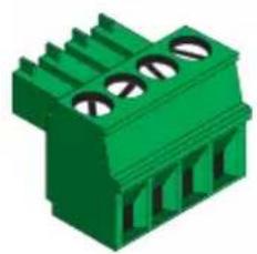
1 x 4-pin captive screw connector
2 x Mounting plates
4 x Mounting screws
1 x 48 V DC power supply

IMPORTANT: Visit http://www.atlona.com/product/AT-OME-EX-WP-KIT-LT for the latest firmware updates and User Manual.
AT-OME-EX-TX-WP-LT
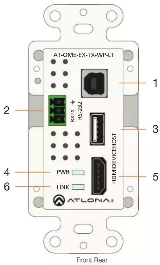
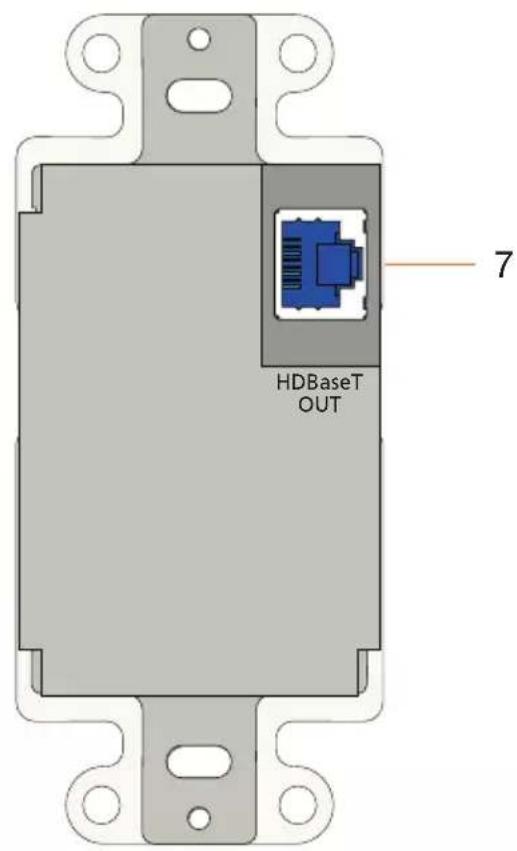
1 HOST
Connect a USB cable from the computer to this port.
2 RS-232
Connect an RS-232 control system to this port. Connect the included 3-pin captive screw connector to this receptacle. Refer to AT-OME-EX-TX-WP-LT RS-232 (page 4) for more information. Note that this port is covered by a plate and must be removed to expose the RS-232 port.
3 DEVICE
Connect a USB device, such as a speakerphone, to this port. This port provides 2.5 W of power.
4 PWR
This LED indicator glows solid green when the unit is powered. Refer to AT-OME-EX-TX-WP-LT LED Indicators (page 8) for more information.
5 HDMI
Connect an HDMI cable from this port to a UHD/HD source.
6 LINK
This LED indicator glows solid amber to indicate that the HDBaseT signal integrity is good. Refer to AT-OME-EX-TX-WP-LT LED Indicators (page 8) for more information.
7 HDBaseT OUT
Connect a category cable from this port to the HDBaseT IN port of the AT-OME-EX-RX-LT.
AT-OME-EX-RX-LT
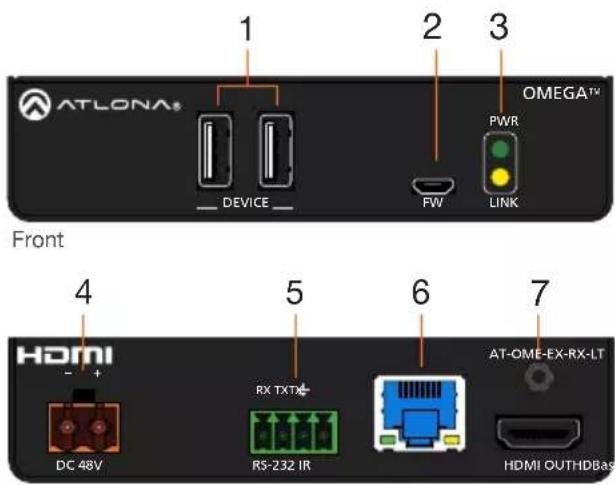
Rear
1 DEVICE
Connect up to two USB 2.0 devices (e.g. mouse, keyboard, etc.) to these ports. These ports provide 2.5 W per USB device.
2 FW
Not used. When updating the AT-OME-EX-TX-WP-LT, the AT-OME-EX-RX-LT will also be updated. Note that both units must be connected using the HDBaseT ports.
3 PWR / LINK
The PWR LED indicator will glow green when the AT-OME-EX-RX-LT is powered. The LINK LED indicator glows yellow when a solid link is established between the AT-OME-EX-TX-WP-LT and AT-OME-EX-RX-LT. Refer to AT-OME-EX-RX-LT LED Indicators (page 9) for more information.
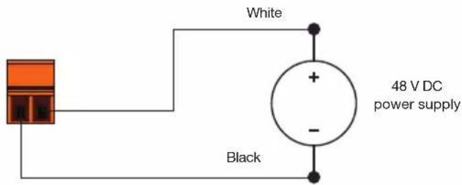
4 DC 48V
Connect the included 2-pin captive screw connector from this receptacle to the power supply. This connection supplies power to the AT-OME-EX-TX-WP-LT. Refer to AT-OME-EX-RX-LT Power (page 5) for more information.
5 RS-232 / IR
Connect the included 4-pin captive screw connector to this receptacle. Refer to AT-OME-EX-RX-LT RS-232 and IR (page 5) for more information.
6 HDBaseT IN
Connect a category cable from this port to the HDBaseT OUT port of the AT-OME-EX-TX-WP-LT. The AT-OME-EX-TX-WP-LT is powered by the AT-OME-EX-RX-LT over HDBaseT.
7 HDMI OUT
Connect an HDMI cable from this port to the display (sink) device.
AT-OME-EX-TX-WP-LT RS-232
The AT-OME-EX-TX-WP-LT provides an RS-232 port which allows communication between a control system and an RS-232 device. This step is optional.
- Gently remove the RS-232 cover from the faceplate using the tip of a small regular screwdriver.
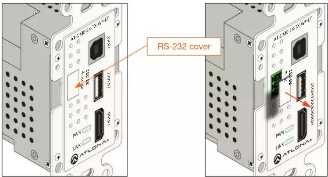
- Use wire strippers to remove a portion of the RS-232 cable jacket.
- Remove at least 3/16" (5 mm) from the insulation of the RX, TX, and GND wires.
- Insert the TX, RX, and GND wires into correct terminal using the included 3-pin captive screw connector.
- Connect the opposite end of the cable to the control system.

natural_image
Green 3D model of a mechanical connector or terminal block (no text or symbols visible)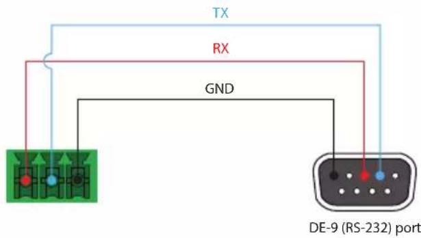

NOTE: Typical DE-9 connectors use pin 2 for TX, pin 3 for RX, and pin 5 for ground. On some devices functions of pins 2 and 3 are reversed.
AT-OME-EX-RX-LT RS-232 and IR
The AT-OME-EX-RX-LT provides pass-through transport of RS-232 protocol and/or IR over HDBaseT, which allows communication between a control system and an RS-232 or IR device. This step is optional.
- Use wire strippers to remove a portion of the cable jacket.
- Remove at least 3/16" (5 mm) from the insulation of the RX, TX, and GND wires for the RS-232 connection.
- Insert the TX, RX, and GND wires into correct terminal using one of the included 4-pin captive screw connectors.
- Repeat step 2 for the S and GND wires for the IR connection.
- Insert the S (signal) wire in to the TX terminal and the ground wire to the GND terminal.
- Tighten the captive screws to secure the wires in place. Do not over-tighten or use high-torque devices to prevent damage to the connector.

NOTE: Typical DE-9 connectors use pin 2 for TX, pin 3 for RX, and pin 5 for ground. On some devices functions of pins 2 and 3 are reversed. Note that the signal (S) pin for the IR is labeled as "TX" on the port.
natural_image
Green 3D component with three circular holes and vertical fins (no text or symbols)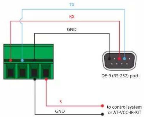
AT-OME-EX-RX-LT Power
-
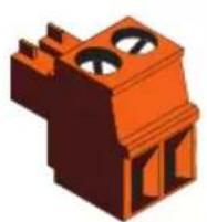
Locate the included orange captive-screw connector, and loosen the screws to allow room to insert the copper wiring.
-
Wire the included power supply to the connector, as shown below. Do not use high-torque devices, when securing the wires to the captive-screw connector, as this may damage the screws and/or connector.
Faceplate Removal and Assembly
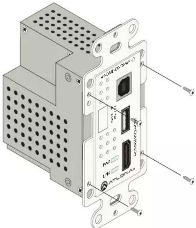
Removal of the faceplate requires that the AT-OME-EX-TX-WP-LT be disassembled from the electrical box or mud ring. A small Phillips-head screwdriver is required to remove the faceplate.
- Unscrew the four Phillips-head screws from the sides of the faceplate, as shown:
-
Gently remove the faceplate by pulling it away from the enclosure.
-
Attach the new faceplate, then secure it using the four Phillips-head screws. Do not over-tighten or apply high-torque devices to the screws. Doing so may damage the faceplate and/or the screws.
-
Install the AT-OME-EX-TX-WP-LT into the electrical box or mud ring.
-
Reattach the wallplate.
Installation
AT-OME-EX-TX-WP-LT
- Connect a category cable, from the HDBaseT OUT port on the rear of the AT-OME-EX-TX-WP-LT, to the HDBaseT IN port on the AT-OME-EX-RX-LT.
| Cable Max. Distance @ 4K Max. Distance @ 1080p | |
| CAT5e / CAT6 115 feet (35 meters) 200 feet (60 meters) | |
| CAT6a / CAT7 130 feet (40 meters) 230 feet (70 meters) |
*Atlona recommends TIA/EIA 568-B termination for optimal performance.

IMPORTANT: Stranded or patch cables are not recommended due to performance issues.
- Connect an HDMI cable from the UHD/HD source to the HDMI port.
- OPTIONAL: Connect a USB cable from the host computer to the HOST port.
- OPTIONAL: Connect a USB device, such as a speakerphone to the DEVICE port. This port provide 2.5 W of power to USB devices.
- OPTIONAL: Connect an RS-232 cable between a control system and the RS-232 port on the AT-OME-EX-TX-WP-LT. Refer to AT-OME-EX-TX-WP-LT RS-232 (page 4) for more information.
AT-OME-EX-RX-LT
- Connect a UHD/HD display to the HDMI OUT port.
- Connect up to two USB devices (mouse, keyboard, etc.) to the DEVICE ports. These ports provide 2.5 W per USB device.
- OPTIONAL: Connect the RS-232 device to the RS-232 port on the AT-OME-EX-RX-LT. Refer to AT-OME-EX-RX-LT RS-232 and IR (page 5) for more information.
- OPTIONAL: Connect an IR emitter to the IR port on the transmitter. Connect an IR receiver to the IR port on the AT-OME-EX-RX-LT. Refer to AT-OME-EX-RX-LT RS-232 and IR (page 5) for more information.
- Connect the included 48 V DC power supply to the DC 48V power receptacle on the ATOME-EX-RX-LT.
- Connect the power supply to an available AC outlet.
AT-OME-EX-TX-WP-LT LED Indicators
The PWR and LINK LED indicator provide basic information on the current status of the ATOME-EX-TX-WP-LT.
| PWR Description | |
| Solid green Unit is powered. | Normal operating mode. |
Blinking green  | Unit is in firmware update mode. Refer to Updating the AT-OME-EX-TX-WP-LT Firmware (page 12) for more information. |
Off Unit is not power  | Make sure that the category cable between the HDBaseT IN port on the AT-OME-EX-TX-WP-LT and the HDBaseT OUT port on the AT-OME-EX-RX-LT is secure.Make sure that the power supply, on the AT-OME-EX-RX-LT, is connected to an active AC outlet. |
| LINK Description | |
| Solid amber The link integrity | between the AT-OME-EX-TX-WP-LT and the AT-OME-EX-RX-LT is good. |
| Blinking amber Poor signal int | egrity between the AT-OME-EX-TX-WP-LT and the AT-OME-EX-RX-LT.Make sure that the category cable between the HDBaseT IN port on the AT-OME-EX-TX-WP-LT and the HDBaseT OUT port on the AT-OME-EX-RX-LT is secure.The category cable may be compromised. Try using a different category cable. Make sure that the cable is solid core. Stranded or patch cables are not recommended. |
| Off The link integrity between | the AT-OME-EX-TX-WP-LT and the AT-OME-EX-RX-LT is compromised.Check the category cable between the HDBaseT IN port on the AT-OME-EX-TX-WP-LT and the HDBaseT OUT port on the AT-OME-EX-RX-LT. |
AT-OME-EX-RX-LT LED Indicators
The PWR and LINK LED indicator provide basic information on the current status of the ATOME-EX-RX-LT.
| PWR Description | |
| Solid green AT-OME-EX-RX-LT is not | LT is powered. |
| Off AT-OME-EX-RX-LT is not | powered.·Verify that the locking connector is securely fastened to the power receptacle.·Make sure that the power supply is connected to an active AC outlet. |
| LINK Description | |
| Solid yellow The link integrity | between the AT-OME-EX-TX-WP-LT and the AT-OME-EX-RX-LT is good. |
| Blinking yellow Poor signal int | egrity between the AT-OME-EX-TX-WP-LT and the AT-OME-EX-RX-LT.Make sure that the category cable between the HDBaseT IN port on the AT-OME-EX-TX-WP-LT and the HDBaseT OUT port on the AT-OME-EX-RX-LT is secure.The category cable may be compromised. Try using a different category cable. Make sure that the cable is solid core. Stranded or patch cables are not recommended. |
| Off The link integrity betwe | the AT-OME-EX-TX-WP-LT and the AT-OME-EX-RX-LT is compromised.Check the category cable between the HDBaseT IN port on the AT-OME-EX-TX-WP-LT and the HDBaseT OUT port on the AT-OME-EX-RX-LT. |
Mounting Instructions
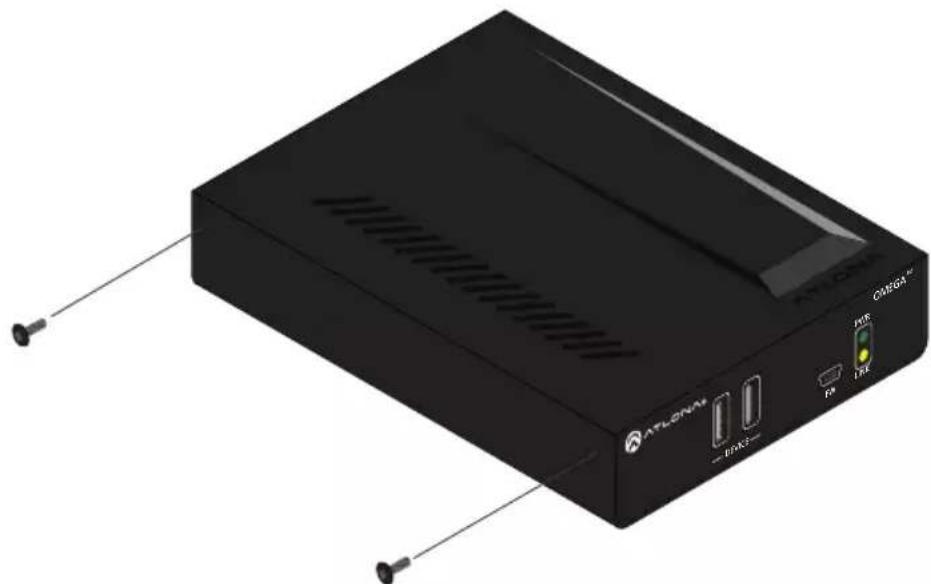
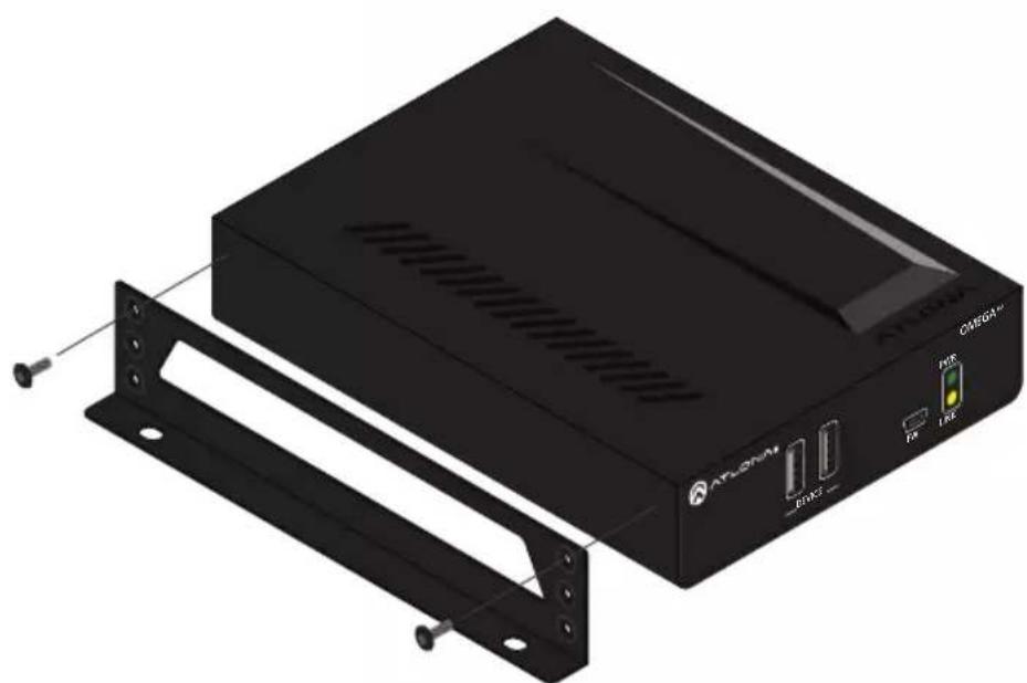
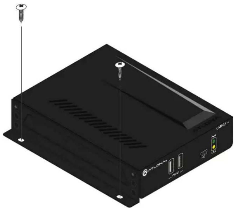
The AT-OME-EX-RX-LT provides two mounting brackets, which can be used to attach the AT-OME-EX-RX-LT to any flat surface. Use the two enclosure screws, on the sides of the AT-OME-EX-RX-LT to attach the mounting brackets.
- Using a small Phillips screwdriver, remove the two screws from the left side of the enclosure.
natural_image
Exterior view of a black ATLEGNAM device with ventilation slots and ports (no readable text or symbols beyond branding)-
Position one of the mounting brackets, as shown below, aligning the holes on the side of the enclosure with one set of holes on the mounting bracket.
-
Use the screws from Step 1 to attach the mounting bracket.
natural_image
Exterior view of a black CMBG device with ventilation slots and external mounting bracket (no text or symbols on main body)-
Repeat these steps to attach the second mounting bracket to the opposite side of the ATOME-EX-RX-LT.
-
Mount the AT-OME-EX-RX-LT to a flat surface using the oval-shaped holes, on each mounting bracket. If using a drywall surface, a #6 drywall screw is recommended.
natural_image
Black electronic device labeled 'ATLORA' with screw and indicator lights, no readable text or symbols beyond brandingUpdating the Firmware
Requirements:
• AT-OME-EX-TX-WP-LT
• AT-OME-EX-RX-LT
- Firmware file
• Computer running Windows
• USB-A to USB-B cable

IMPORTANT: Both units must be connected to apply the firmware update to both the AT-OME-EX-TX-WP-LT and AT-OME-EX-RX-LT. The update process can take up to five minutes to complete.
- Disconnect power from the AT-OME-EX-TX-WP-LT.
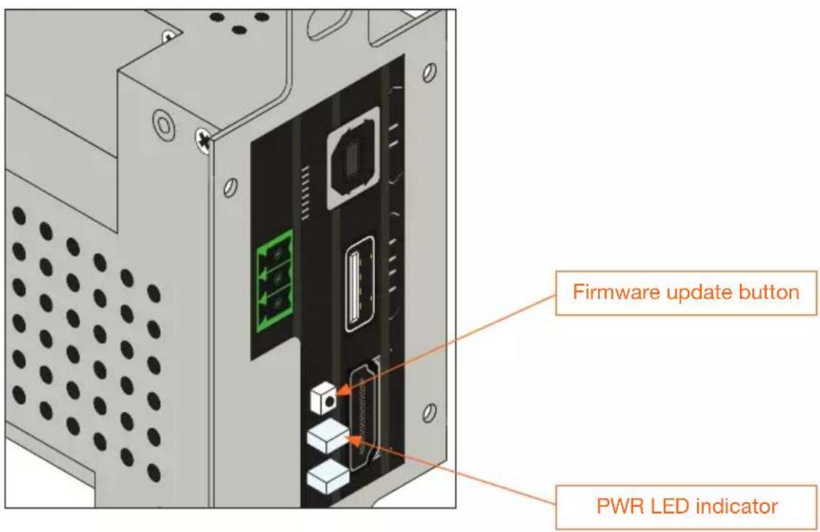
- Remove the faceplate to access the hidden "firmware update" button, located above the PWR LED indicator. Refer to Faceplate Removal and Assembly (page 6) for more information.
- Connect a USB cable from the HOST port on the AT-OME-EX-TX-WP-LT to a PC, using a USB-A to USB-B cable.
-
Simultaneously press and hold the firmware update button, while reconnecting the power. The PWR LED indicator will be blinking green.
-
The USB UPDATE folder will be displayed. If this folder is not displayed, automatically, select the USB UPDATE drive from Windows Explorer. Refer to the next page for an illustration.
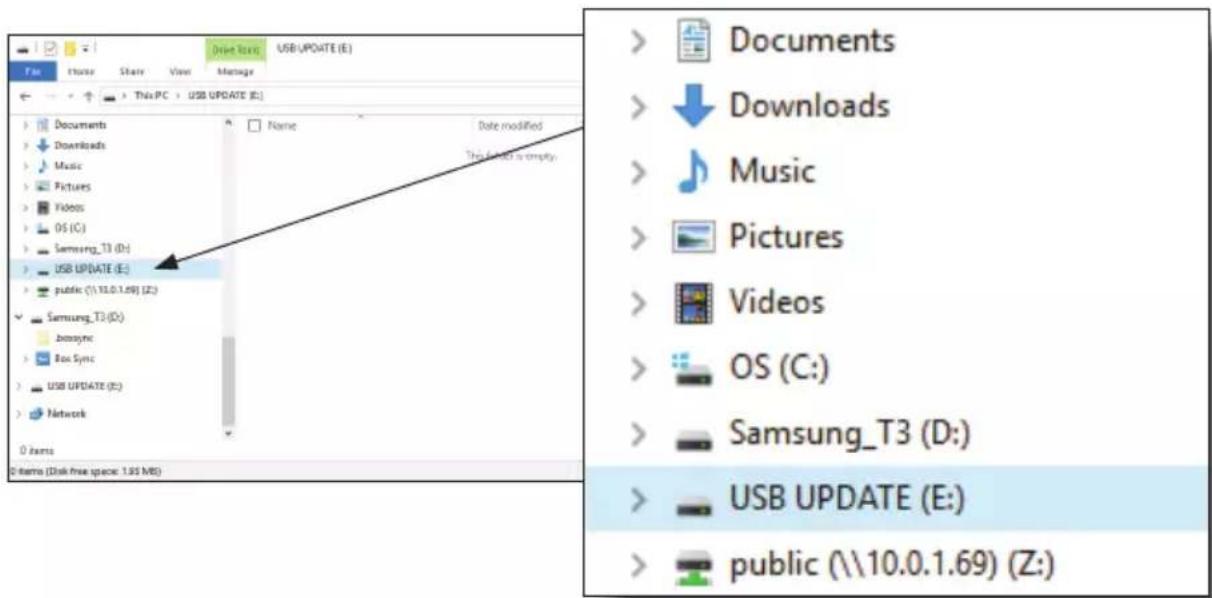
- Drag and drop the firmware file into the USB drive folder.
- After the firmware file has been placed in the folder, the firmware update process will begin. During the update process, the PWR LED indicator will flash green.
- Once the update process is complete, the AT-OME-EX-TX-WP-LT will automatically reboot.
- Once the PWR LED returns to solid green, the firmware update process is complete.
Notes
Notes
Warranty
To view the product warranty, use the following link or QR code: https://atlona.com/warranty/.

Version 2
English Declaration of Conformity
The English version can be found under the resources tab at: https://atlona.com/product/at-ome-ex-wp-kit-lt/.

Chinese Declaration of Conformity 中国RoHS合格声明
由SKU列出於:
https://atlona.com/about-us/china-rohs/.


The terms HDMI, HDMI High-Definition Multimedia Interface, and the HDMI Logo are trademarks or registered trademarks of HDMI licensing Administrator, Inc.

ATLONA.
a PNDUT company
US International
atlona.com • 408.962.0515 • 41.43.508.4321
© 2022 Atlona Inc. All rights reserved. "Atlona" and the Atlona logo are registered trademarks of Atlona Inc. All other brand names and trademarks or registered trademarks are the property of their respective owners. Pricing, specifications and availability subject to change without notice. Actual products, product images, and online product images may vary from images shown here.
25297-R2
- Package Contents
- HOST
- RS-232
- DEVICE
- PWR
- HDMI
- LINK
- HDBaseT OUT
- AT-OME-EX-RX-LT
- DEVICE
- FW
- PWR / LINK
- DC 48V
- RS-232 / IR
- HDBaseT IN
- HDMI OUT
- AT-OME-EX-TX-WP-LT RS-232
- AT-OME-EX-RX-LT RS-232 and IR
- AT-OME-EX-RX-LT Power
- Faceplate Removal and Assembly
- Installation
- AT-OME-EX-TX-WP-LT
- AT-OME-EX-TX-WP-LT LED Indicators
- AT-OME-EX-RX-LT LED Indicators
- Mounting Instructions
- Updating the Firmware
- Requirements:
- Warranty
- English Declaration of Conformity
- Chinese Declaration of Conformity 中国RoHS合格声明
Brand : Atlona
Model : AT-OME-EX-WP-KIT-LT
Category : Audio/video extender