AT-UHD-EX-100CE-RX - Audio/video extender Atlona - Free user manual and instructions
Find the device manual for free AT-UHD-EX-100CE-RX Atlona in PDF.


| Product Type | Audio/video extender (receiver) |
| Model | AT-UHD-EX-100CE-RX |
| Maximum Extension Distance (4K) | 328 ft (100 m) over CAT6a/7 solid core |
| Maximum Extension Distance (1080p) | 328 ft (100 m) over CAT5e/6 |
| Supported Video Resolutions | Up to 4K UHD (3840x2160 @ 60Hz 4:2:0 8-bit), 1080p, 3D, VESA |
| HDCP Compliance | HDCP 2.2 |
| Audio Support | PCM, Dolby Digital, Dolby TrueHD, DTS-HD Master Audio, Dolby Atmos (up to 7.1) |
| Pass-through Signals | IR, RS-232, Ethernet (bi-directional) |
| Power Over Ethernet (PoE) | Yes (powered from transmitter via HDBaseT) |
| Connectors | HDMI out, HDBaseT in (RJ45), RS-232 (captive screw), IR IN/OUT (captive screw), Ethernet (RJ45), USB Mini-B (firmware) |
| Dimensions (H x W x D) | 25 x 109 x 127 mm (0.98 x 4.29 x 5.00 in) |
| Weight | 0.39 kg (0.86 lbs) |
| Operating Temperature | 0°C to 50°C (32°F to 122°F) |
| Storage Temperature | -20°C to 60°C (-4°F to 140°F) |
| Humidity | 20% to 90% non-condensing |
| Video Bandwidth | 10.2 Gbps |
| Chroma Subsampling | 4:4:4, 4:2:2, 4:2:0 |
| Color Depth | 8-bit, 10-bit, 12-bit |
| CEC Support | Yes |
| 3D Pass-through | Yes |
| Firmware Upgrade | Via USB Mini-B (Windows PC) |
| Included Accessories | Captive screw connectors, mounting ears, IR emitter, user manual |
| Certifications | CE, FCC, RoHS |
| Cleaning Instructions | Unplug and wipe with a damp cloth; do not use cleaning fluids or aerosols. |
Frequently Asked Questions - AT-UHD-EX-100CE-RX Atlona
User questions about AT-UHD-EX-100CE-RX Atlona
0 question about this device. Answer the ones you know or ask your own.
Ask a new question about this device
Download the instructions for your Audio/video extender in PDF format for free! Find your manual AT-UHD-EX-100CE-RX - Atlona and take your electronic device back in hand. On this page are published all the documents necessary for the use of your device. AT-UHD-EX-100CE-RX by Atlona.
USER MANUAL AT-UHD-EX-100CE-RX Atlona
4K/UHD HDMI Over 100M HDBaseT TX/RX with Ethernet, Control, and PoE
AT-UHD-EX-100CE-TX & AT-UHD-EX-100CE-RX AT-UHD-EX-100CE-KIT
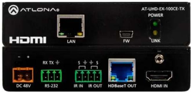
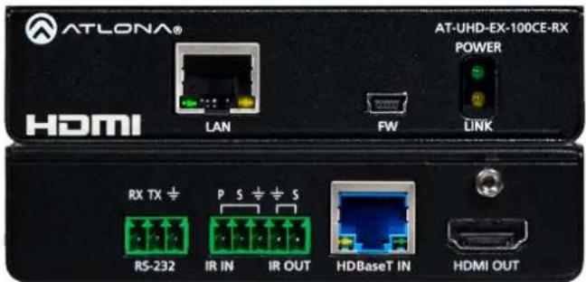
Table of Contents
- Introduction 3
- Package Contents 3
- Features
- Before You Start 3
- Category Cable 4
- Panel Descriptions
a. Front Panel 5
b. Rear Panel 6
- Captive Screw Connectors 7
- Connection Diagram 8-9
- Specifications 10
- Safety Information 11
Introduction
Pass through support of 4K (UHD), 2560x2048, IR, RS-232, bi-directional Ethernet, and lossy/lossless audio signals up to 328ft (100m). The 100CE extenders provide an affordable, high quality, solution for your audio and video needs.
Package Contents
Kit
• 1 x AT-UHD-EX-100CE-TX
- 1 x AT-UHD-EX-100CE-RX
• 1 x 48V DC power supply
- 5 x Female captive screw connector (2 pin (x1): power, 3 pin (x2): RS-232, and 5 pin (x2): IR)
- 2 x Pair of wall/table mount ears
- 2 x Pair of screws for wall/mount ears
• 1 x IR emitter (AT-IR-CS-TX)
- 1 x User manual
TX
• 1 x AT-UHD-EX-100CE-RX
- 1 x 48V DC power supply
- 2 x Female captive screw connector (3 pin: RS-232 and 5 pin: IR)
- 1 x Pair of wall/table mount ears
- 1 x Pair of screws for wall/mount ears
• 1 x IR emitter (AT-IR-CS-TX)
- 1 x User manual
RX
• 1 x AT-UHD-EX-100CE-RX
- 2 x Female captive screw connector (3 pin: RS-232 and 5 pin: IR)
- 1 x Pair of wall/table mount ears
- 1 x Pair of screws for wall/mount ears
• 1 x IR emitter (AT-IR-CS-TX)
- 1 x User manual
Features
- Extends IR, RS-232, Ethernet, and audio/visual content up to 328ft over a single category cable
• Supports resolutions up to 4K (UHD) 60Hz @ chroma sub-sampling 4:2:0 8-bit - IR ports for use with IR remote controls and 3rd party IR controllers
• Bi-directional Ethernet pass through - Provides PoE (Power over Ethernet)
- Multichannel audio pass through up to Dolby TrueHD, DTS-HD Master Audio, and Dolby Atmos
• Full 3D pass through
• HDCP 2.2 compliant
• Field updatable firmware
Before You Start
- When installing the extenders DO NOT:
Cover the vents
Install into a sealed wall
Install into an area without adequate air ventilation
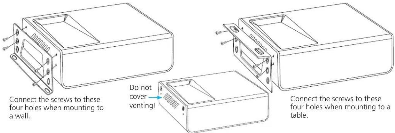
*Remove the side screws from the case and use for bracket installation
Category Cable
For the category cables used in the installation of these products, please be sure to use a 568B termination as pictured below:
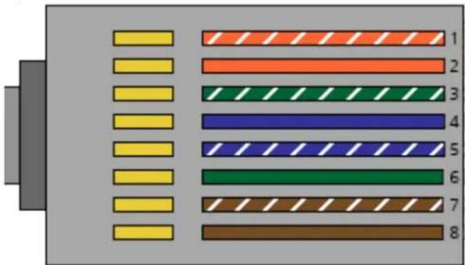
- White - Orange
- Orange
- White - Green
- Blue
- White - Blue
- Green
- White - Brown
- Brown
Use the table below to verify the best category cable for the installation.
| Performance Rating Type of LAN cable | |||
| Wiring Shielding CAT | 5e/6 CAT6a/7 | ||
| Solid | Shielded (STP/FTP) | *** **** | |
| UnShielded (UTP) ** N/A | |||
| Stranded - Patch cable(Not recommended) | Unshielded (UTP) * N/A | ||
| Shielded (STP/FTP) | * N/A | ||
| Termination Please use EIA/TIA-568-B termination | |||
Important! 4K (UHD) signals are sensitive to cable quality and installation technique. It is recommended to use CAT6a/7 solid core cables for best results.
Note: For cable distances see the specifications on page 10
Connector
Connector type and size is very important to ensure extenders work correctly. Please use the matching cable type with the correct RJ45 connector.
CAT5e and CAT 6 cables should use only CAT5e RJ45 connectors
CAT6a cables should use only CAT6a connectors
CAT7 cables should use only CAT7 connectors
Using the wrong size of connectors may result in interference causing loss of signal.
Important! "EZ RJ45 connectors" are not recommended with HDBaseT extenders. Doing so may result in stray EMI/RFI signals to be picked up and interfere with audio and video transmission.
Panel Description
TX
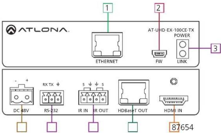
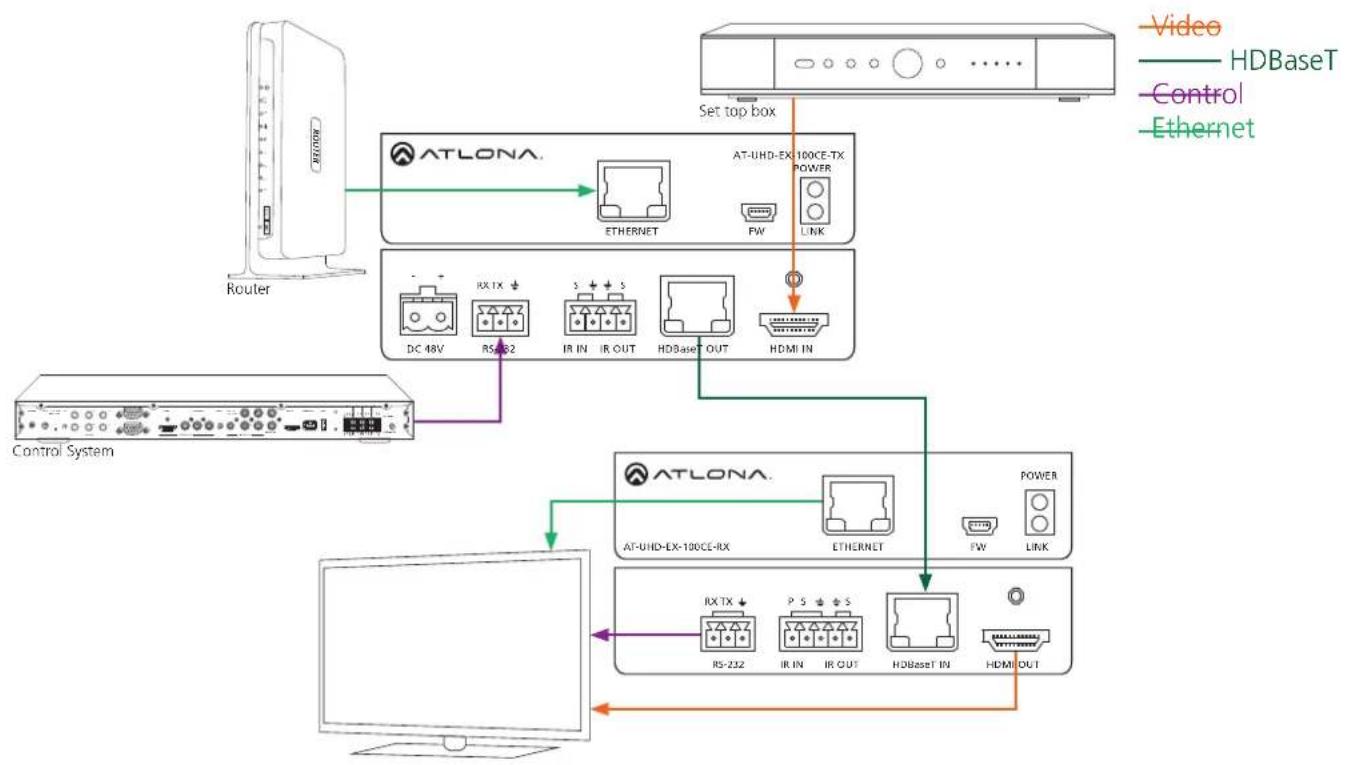
- Ethernet - Connect to a router to send Ethernet signals
- Firmware - Use a Mini-B USB to USB A cable to connect to a Windows computers for updating
- Yellow Link LED: Signal indicator for the HDBaseT OUT port
Solid - Good signal from the CAT port
Blinking - Category cable is disconnected or not receiving signals
No Light - No signal is being received from the CAT port
Green Power LED: Power indicator
Solid - Plugged in and receiving power
Blinking - Power is intermittent or there is a problem with the cable
No Light - No power is passing from the wall outlet to the transmitter (check the cable or outlet)
- DC 48V - Connect included captive screw power adapter here
- RS-232 - Bidirectional RS-232, send signal to or from a control system, PC, source, or display
- IR - Connect IR emitter (included) or 3rd party control box to this port
- HDBaseT OUT - Connect a category cable from here to an AT-UHD-EX-100CE-RX (included in KIT)
- HDMI IN - Connect HDMI or DVI (with adapter) source here
Ex. Blu-ray player, cable box, HDDA series, H2H series, etc
RX
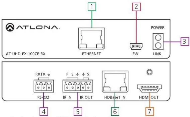
- Ethernet - Connect to a display to send Ethernet signals
-
Firmware - Use a Mini-B USB to USB A cable to connect to a Windows computers for updating
-
Yellow Link LED: Signal indicator for the HDBaseT IN port Solid - Good signal from the CAT port
Blinking - CAT port is disconnected or not receiving a signal
No Light - No signal is being received from the CAT port Green Power LED: Power indicator
Solid - Plugged in and receiving power
Blinking - Power is intermittent or there is a problem with the cable
No Light - No power is passing from the transmitter to the receiver
Note: Check the category cable or the AC outlet for the transmitter
- RS-232 - Bidirectional RS-232, send signal to or from a control system, PC, source, or display
- IR - Connect IR emitter (included) or receiver (AT-IR-CS-RX sold separately) to this port
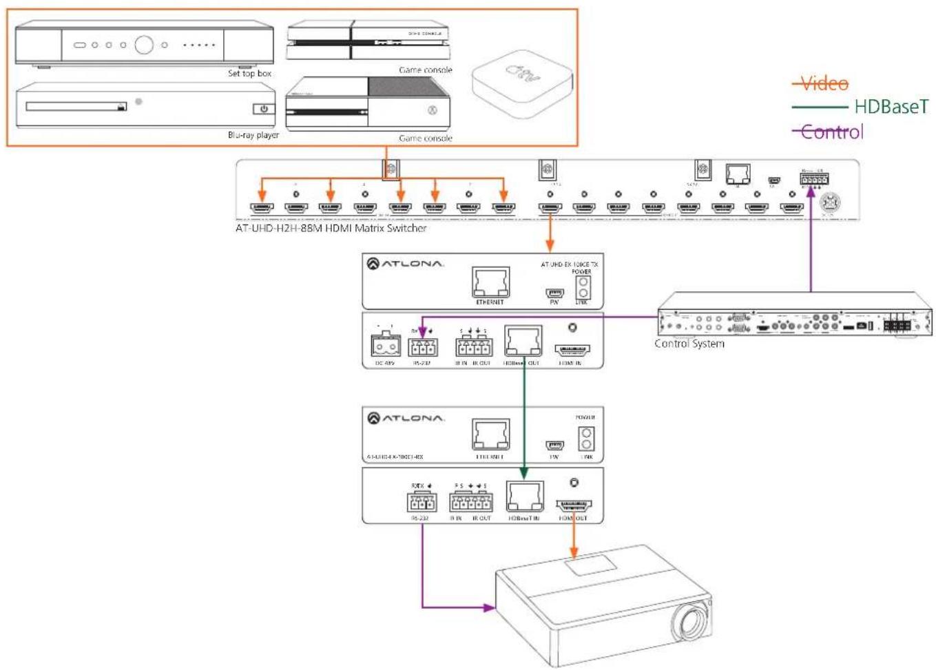
- HDBaseT IN - Connect a category cable from here to an AT-UHD-EX-100CE-TX (included in KIT) or HDBaseT matrix
- HDMI OUT - Connect HDMI or DVI (with adapter) display here
Captive Screw
Captive screw connectors are an added feature on the UHD extender. The captive screw connectors allow you to cut cables down to a suitable length, reduce cable clutter, while providing a more reliable connection.
Connecting
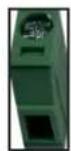
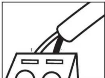
When connecting the cables to the female captive screw connector it is important that the wires be terminated correctly. The female captive screw connector has a contact plate at the top and must have the wires touching it for signal to pass. When wired correctly (see picture A) the signal will pass, incorrectly (see picture B) no signal will pass.
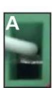
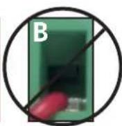
The captive screw connectors have a contact bar that is adjusted to compress the wire against the top contact plate. Use the screws at the top of the connector to compress the wire against the contact plate.

Clockwise
Turn the screws clockwise to raise the contact bar to the upper contact plate and hold the wires in place.

Counter Clockwise
Turn the screws counter clockwise to lower the contact bar to release the wires.
Power
RS-232
IR
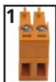
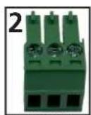
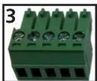
Female captive screw connectors are included: Power (see picture 1), RS-232 (see picture 2), and IR (see picture 3).
Black: - White: +
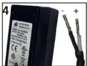
The power cable (picture 4) will have exposed wires. Each wire is encased in a different colored cover.
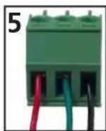
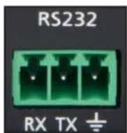
RS-232 pin out will be determined by the RS-232 cable and will connect as Rx (receiver), Tx (transmitter), and ± (ground). (See picture 5)
Pin out color will differ
per RS-232 cable.
Note: The IR receiver is optional for the UHD-EX-100CE-KIT and RX box. The compatible IR receiver (AT-IR-CS-RX) can be purchased through atlona.com.
The wires of the emitter and receiver have been marked to differentiate the pin outs.
natural_image
Simple line drawing of a cylindrical object with two parallel wires extending from it (no text or symbols)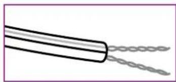
natural_image
Simple line drawing of a coiled cable or wire with two strands (no text or symbols)—— Signal (S) Ground (±)
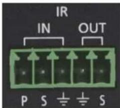
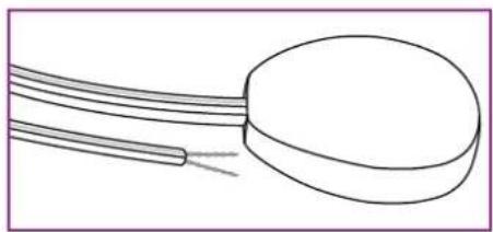
The included IR emitter has two wires: signal and ground. Signal will have a solid line and ground will be blank. The IR emitter will plug into the IR OUT ports.

natural_image
Pure 3D schematic of a rectangular block with a small horizontal bar on the left side (no text or symbols)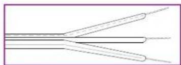
natural_image
Pure electrical circuit lines without any symbols— — Signal (S) Ground (⊥) Power (P)
There are three wires on the IR receiver (AT-IR-CS-RX sold separately): signal, ground, and power. Signal has a dotted line, ground will be blank, and power will have a solid line. The IR receiver will plug into the IR IN ports.
Power Chaining
Multiple kits can be powered by one power supply. The included power supply can support up to 3 kits. To power four kits use the optional power supply AT-PS-483125-C (purchase through atlona.com).
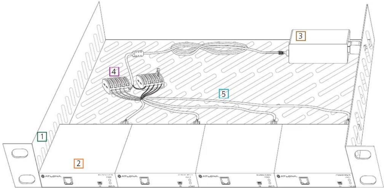
To chain one power supply to three transmitters (four when using AT-PS-483125-C), use two wago splicing connectors, 18/2 AWG stranded wire, a ventilated 1 RU rack shelf, zip ties, and high temperature hook and loop (velcro) strips will be needed.
- 1 RU rack shelf - Should be at least 10in / 254mm deep, fit in a standard 19" rack, and must be well ventilated. Use the rack screws (included with 19" racks) to secure the rack shelf to the back/front of the rack after power chaining set up is completed.
- Transmitters - Place 3 or 4 units on the rack shelf. Use high temperature (up to 185°F / 85°C) hook and loop (velcro) to secure the transmitters to the rack.
- Power supply - Place the included power supply (or the AT-PS-483125-C) on the rack with enough room to connect the included IEC power cable. Use twist ties to secure the power supply and cable to the rack.
- Wago splicing connectors - Connect the wires from the power supply cable to the wago splicers. Connect (model #: 222-415) the white wire (power/+) to one splicer and the black wire (ground/-) to the second splicer.
Note: Only one wire per port.
- 18/2 AWG stranded wire - Connect the individual wires to the wago splicers and the transmitter captive screw connectors. There will be two colors of wires (black/red) which will need
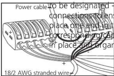
and +. Each color will need to be the same across all sure no signals are crossed. Strip the ends of each wire and the appropriate wago connector and the other to the operative screw connector. Use the zip ties to keep all wires
natural_image
Simple line drawing of a tool interacting with an electronic device (no text or symbols)Connection Diagram (Kit connections)
flowchart
graph TD
    A["Router"] --> B["ATLONA."]
    B --> C["AT-UHD-EX-100CE-TX POWER"]
    C --> D["SET top box"]
    D --> E["Video"]
    D --> F["HDBaseT"]
    D --> G["Control"]
    D --> H["Ethernet"]
    B --> I["DC 48V"]
    B --> J["RX TX ↓"]
    B --> K["RS-A82"]
    B --> L["IR IN"]
    B --> M["IR OUT"]
    B --> N["HDBase T OUT"]
    B --> O["HDMI IN"]
    B --> P["Power"]
    P --> Q["AT-UHD-EX-100CE-RX"]
    Q --> R["ETHERNET"]
    Q --> S["FW"]
    Q --> T["LINK"]
    Q --> U["Power"]
    U --> V["RS-232"]
    U --> W["P S ↓ S"]
    U --> X["IR IN"]
    U --> Y["IR OUT"]
    U --> Z["HDBase T IN"]
    U --> AA["HDMI OUT"]
    B --> AB["Control System"]
    AB --> AC["Computer monitor"]
flowchart
graph TD
    A["AT-UHD-H2H-88M HDMI Matrix Switcher"] --> B["AT-LONA"]
    B --> C["Control System"]
    A --> D["Video"]
    A --> E["HDBaseT"]
    A --> F["Control"]
    B --> G["AT-UHD EX ISOKE TX POWER"]
    B --> H["ETHERNET"]
    B --> I["FOX LINK"]
    B --> J["DC 48V"]
    B --> K["RS-23D"]
    B --> L["IR PN IR OUT"]
    B --> M["HDBase OUT"]
    B --> N["HDMI IN"]
    B --> O["AT-LONA"]
    O --> P["POWER"]
    O --> Q["RS-23D"]
    O --> R["IR IN IR OUT"]
    O --> S["HDBase T IN"]
    O --> T["HDMI OUT"]
Connection Diagram (RX connection)
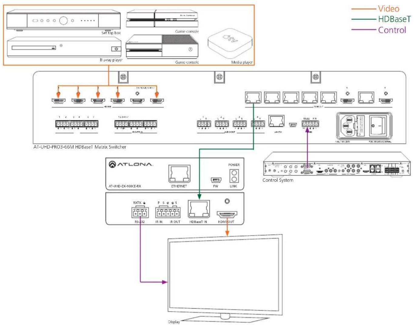
flowchart
graph TD
    A["Video"] --> B["AT-UHD-PRO3-66M HDBaseT Matrix Switcher"]
    C["HDBaseT"] --> D["Control System"]
    E["Video Console"] --> F["AT-UHD-PRO3-66M HDBaseT Matrix Switcher"]
    G["Game console"] --> H["AT-UHD-PRO3-66M HDBaseT Matrix Switcher"]
    I["Blu-ray player"] --> J["AT-UHD-PRO3-66M HDBaseT Matrix Switcher"]
    K["Media player"] --> L["AT-UHD-PRO3-66M HDBaseT Matrix Switcher"]
    M["Power"] --> N["AT-UHD-EX-100CE-RX"]
    O["RXTX"] --> P["R5-232"]
    Q["P 5 5"] --> R["IR IN IR OUT"]
    S["HDBaseT IN"] --> T["HDMI OUT"]
    U["Link"] --> V["FW"]
    W["AUDOUT"] --> X["L 2 n L 3 n"]
    Y["UNTV"] --> Z["RS22 R/N"]
    AA["Display"] --> AB["Computer"]
Connection Diagram (TX connection)
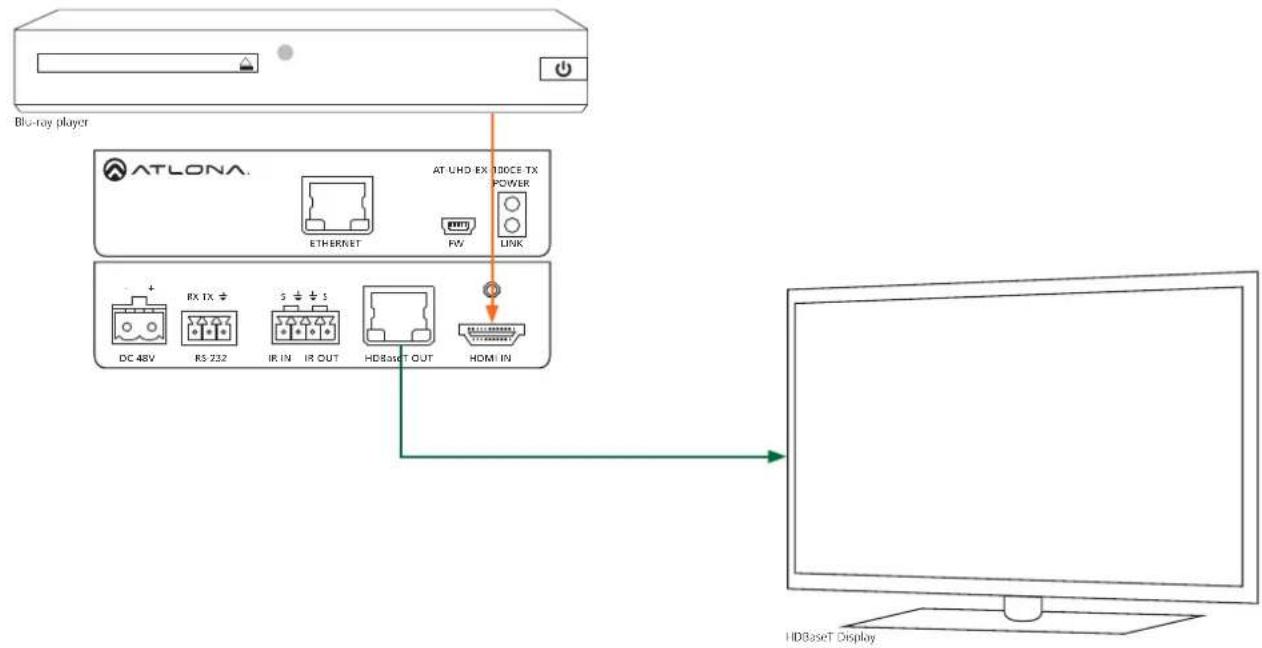
flowchart
graph TD
    A["ATLONA"] -->|Blue-ray player| B["ATUHD BX 100CE TX POWER"]
    A --> C["ETHERNET"]
    A --> D["RV"]
    A --> E["LINK"]
    C --> F["DC 48V"]
    C --> G["RX TX +"]
    C --> H["RS 232"]
    C --> I["S + + 3"]
    C --> J["IR IN"]
    C --> K["IR OUT"]
    C --> L["HDBaseT OUT"]
    C --> M["HDMI IN"]
    N["HDBaseT Display"] --> O["Computer"]
Specifications
Video Resolutions
| Video | 4096x2160@24/25/30/50*/60Hz*, 3840x2160@24/25/30/50*/60Hz*(UHD), 2048x1080p, 1080p@23.98/24/25/29.97/30/50/59.94/601080i@50/59.94/60Hz, 720p@50/59.94/60Hz, 576p, 576i, 480p, 480i |
VESA 2560x2048, 2560x1600, 2048x1536, 1920x1200, 1680x1050,
1600x1200, 1600x900,
1440x900, 1400x1050, 1366x768, 1360x768, 1280x1024, 1280x800,
1280x768, 1152x768, 1024x768, 800x600, 640x4
Colorspace YCbCr, RGB
Chroma Subsampling 4:4:4, 4:2:2, 4:2:0
Color depth 8-bit, 10-bit, 12-bit
Audio
Format - pass through PCM 2Ch, LPCM 5.1, LPCM 7.1, Dolby Digital, DTS 5.1, Dolby Digital
Plus, Dolby TrueHD, DTS-HD Master Audio, Dolby Atmos
Sample Rate 32kHz, 44.1kHz, 48kHz, 88.2kHz, 96kHz, 176.4kHz, 192kHz
Bit rate up to 24-bit
Distance
CAT5e/6 @ 4K up to 70M up to 230 ft
CAT6a/7 @ 4K up to 100M up to 328 ft
CAT5e/6 @ 1080p up to 100M up to 328 ft
HDMI IN/OUT @ 4K up to 5M up to 15 ft
HDMI IN/OUT @ 1080p up to 10M up to 30 ft
Signal
| Bandwidth | 10.2 | Gbps | ||
| CEC | Yes | |||
| HDCP | supports | up | to | 2.2 |
Temperature
| Operating | 0°C | to | 50°C | 32°F | to | 122°F |
| Storage | -20°C | to | 60°C | -4°F | to | 140°F |
Humidity 20 to 90% non-condensing
Power
| Consumption - Kit Supply | 15.2W | Input: | AC100~240V | 50/60Hz |
| Output: | DC48V | 0.83A |
Dimension
| H x W x D | 25 x 109 x 127 (mm) | 0.98 x 4.29 x 5.00 (inch) |
| s 27 x 119 x 127 (mm) | 1.06 x 4.69 x 5.00 (inch) |
Weight
Device 0.39 kg 0.86 lbs
Certification
| Power Supply Product | CE, FCC, cULus, RoHS, CCC, RCM CE, FCC |
**4096x2160@50/60Hz & 3840x2160@50/60Hz supported @ chroma subsampling 4:2:0 8-bit only
Safety Information
Safeguards

To reduce the risk of electric shock, do not expose this product to rain or moisture

If the wall plug does not fit into your local power socket, hire an electrician to replace your obsolete socket.

Do not modify the wall plug. Doing so will void the warranty and safety features.
This equipment should be installed near the socket outlet and the device should be easily accessible in the case it requires disconnection.
Precautions
FCC regulations state that any unauthorized changes or modifications to this equipment, not expressly approved by the manufacturer, could void the user's authority to operate this equipment.
Operate this product using only the included external power supply. Use of other power supplies could impair performance, damage the product, or cause fires.
In the event of an electrostatic discharge this device may automatically turn off. If this occurs, unplug the device and plug it back in.
Protect and route power cords so they will not be stepped on or pinched by anything placed on or against them. Be especially careful of plug-ins or cord exit points from this product.
Avoid excessive humidity, sudden temperature changes or temperature extremes.
Keep this product away from wet locations such as bathtubs, sinks, laundries, wet basements, fish tanks, and swimming pools.
Use only accessories recommended by Atlona to avoid fire, shock, or other hazards.
Unplug the product before cleaning. Use a damp cloth for cleaning and not cleaning fluid or aerosols. Such products could enter the unit and cause damage, fire, or electric shock. Some substances may also mar the finish of the product.
Never open, remove unit panels, or make any adjustments not described in this manual. Attempting to do so could expose you to dangerous electrical shock or other hazards. It may also cause damage to your product. Opening the product will void the warranty.
Do not attempt to service the unit. Disconnect the product and contact your authorized Atlona reseller or contact Atlona directly.
Warranty

To view the product warranty, use the following link or QR code: https://atlona.com/warranty/.
- 4K/UHD HDMI Over 100M HDBaseT TX/RX with Ethernet, Control, and PoE
- Table of Contents
- Introduction
- Package Contents
- Kit
- TX
- RX
- Features
- Before You Start
- Category Cable
- Connector
- Panel Description
- Captive Screw
- Connecting
- Power Chaining
- Specifications
- Audio
- Distance
- Signal
- Power
- Weight
- Certification
- Safety Information
- Safeguards
- Precautions
- Warranty
Brand : Atlona
Model : AT-UHD-EX-100CE-RX
Category : Audio/video extender