
OR-VID-MA-1079 - Doorbell VIBELL - Free user manual and instructions
Find the device manual for free OR-VID-MA-1079 VIBELL in PDF.


| Product Type | Video Door Phone (Chime) |
| Brand | VIBELL |
| Model | OR-VID-MA-1079 |
| Monitor Screen Size | 8" LCD touchscreen |
| Monitor Resolution | 1024x600 |
| Outdoor Unit Camera Resolution | 2 MP, 1920x1080 (Full HD) |
| Outdoor Unit Viewing Angle | 108° horizontal / 54° vertical |
| Night Vision | IR LEDs, range approx. 1 m |
| Outdoor Unit Ingress Protection | IP65 |
| Power Supply (Monitor) | 24V DC 1A |
| Power Consumption (Monitor) | Standby <3.5W, Work <6W |
| Power Consumption (Outdoor) | Standby <1.5W, Work <3W |
| Installation | 2-wire, surface-mounted |
| Wi-Fi Frequency | 2.4 GHz (802.11 b/g/n) |
| RFID Reader | 13.56 MHz, up to 200 users |
| SD Card Support | microSD up to 128 GB (not included) |
| Electric Strike Control | 12V DC, max 300 mA (powered from monitor) |
| Gate Control | Dry contact |
| Number of Ringtone Melodies | 5 pre-installed + custom via SD card |
| Mobile App | Tuya Smart (free, iOS & Android) |
| Expandability | Up to 6 monitors, 2 outdoor units, 2 IP cameras |
| Monitor Dimensions (WxHxD) | 215 x 153 x 21 mm |
| Outdoor Unit Dimensions (WxHxD) | 67 x 159 x 31 mm |
| Monitor Weight | 0.455 kg |
| Outdoor Unit Weight | 0.245 kg |
| Operating Temperature | -20°C to +50°C |
| Materials | Monitor: plastic; Outdoor unit: aluminum |
| Cleaning | Use dry cloth for camera lens; avoid chemical cleaners |
| Safety Notes | Disconnect power before installation; do not immerse; do not open or repair yourself |
| Spare Parts / Repairability | No user-serviceable parts; microSD card replaceable |
Frequently Asked Questions - OR-VID-MA-1079 VIBELL
User questions about OR-VID-MA-1079 VIBELL
0 question about this device. Answer the ones you know or ask your own.
Ask a new question about this device
Download the instructions for your Doorbell in PDF format for free! Find your manual OR-VID-MA-1079 - VIBELL and take your electronic device back in hand. On this page are published all the documents necessary for the use of your device. OR-VID-MA-1079 by VIBELL.
USER MANUAL OR-VID-MA-1079 VIBELL

SPIS TREŚCI
- UWAGI WSTĘPNE ...... 3
- CHARAKTERYSTYKA....4
- DANE TECHNICZNE......4
- BUDOWA ZESTAWU .... 5
- MONTAŻ 6
MONTAŻ MONITORA....6
MONTAŻ PANELU ZEWNETRZNEGO....6
- SCHEMATY PODŁĄCZENIA....7
- OBSŁUGA URZĄDZENIA....9
MENU GŁOWNE....9
MONITORING Z PANELU ZEWNETRZNEGO....10
MONITORING Z KAMERY IP 11
NAGRANIA I PAMIĘĆ....11
POŁĄCZENIE I ROZMOWA....12
DZIENNIK....12
- USTAWIENIA ....13
MENU USTAWIEN....13
USTAWIENIA SYSTEMOWE 14
USTAWIENIA AMINISTATORA....15
ZARZĄDZANIE KARTAMI I BRELOKAMI ZBLIŻENIOWYMI....15
USTAWIENIA PANELU ZEWNETRZNEGO 16
USTAWIENIA KAMERY IP 17
USTAWIENIA SIECIOWE 17
USTAWIENIA RAMKI CYFROWEJ....18
USTAWIENIA ZAAWANSOWANE....19
INFORMACJE SYSTEMOWE 19
- PODŁĄCZENIE KAMERY IP 20
2MP, 1920x1080, 1080p
54° / 108°
diody IR
4
ok, 1m

Operating and installation instructions
Video doorphone set Xiran
OR-VID-MA-1079/B
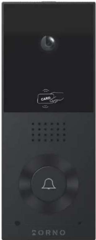
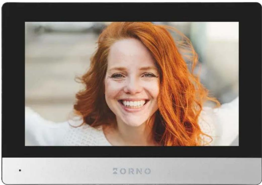
TABLE OF CONTENTS
- SAFETY INSTRUCTIONS .... 3
- CHARACTERISTICS OF THE SET ....4
- TECHNICAL DATA....4
- SET CONSTRUCTION....5
- INSTALLATION ....6
MONITOR INSTALLATION....6
OUTDOOR UNIT WITH CAMERA INSTALLATION....6
- WIRING DIAGRAMS ...... 7
- SET OPERATION....9
MAIN MENU 9
OUTDOOR UNIT MONITORING 10
IP CAMERA MONITORING ....11
RECORDINGS AND STORAGE 11
CONNECTION AND CONVERSATION....12
EVENT....12
- SETTINGS ....13
SETTING MENU 13
SYSTEM SETTINGS....14
ADMINISTRATOR SETTINGS....15
PROXIMITY CARDS AND TAGS MANAGEMENT .... 15
OUTDOOR UNIT SETTINGS....16
IP CAMERA SETTINGS....17
NETWORK SETTINGS....17
DIGITAL FRAME SETTINGS....18
ADVANCED SETTINGS....19
SYSTEM INFORMATION .... 19
- IP CAMERA CONNECTION ....20
WIRED CONNECTION 20
WIRELESS CONNECTION 21
- MOBILE APP INSTALATION....22
LOGIN 22
PAIRING THE DEVICE WITH THE PHONE 22
INVITING USERS 24
- CLEANING AND MAINTENANCE 24
- TROUBLESHOOTING....25
1. SAFETY INSTRUCTIONS
Before using the device, read this Service Manual and keep it for future use. The manufacturer is not responsible for any damage that can result from improper device installation or operation. Any repair or modification carried out by yourselves results in loss of guarantee. Installation and commissioning of the equipment by the customer are possible if the installer has basic knowledge of electrical systems and the use of proper tools. In view of the fact that the technical data are subject to continuous modifications, the manufacturer reserves a right to make changes to the product characteristics and to introduce different constructional solutions without deterioration of the product parameters or functional quality. Additional information about ORNO products is available at www.orno.pl. Orno-Logistic Sp. z o.o. holds no responsibility for the results of non-compliance with the provisions of the present Manual Orno-Logistic Sp. z o.o. reserves the right to make changes to the Manual - the latest version of the Manual can be downloaded from www.orno.pl Any translation/interpretation rights and copyright in relation to this Manual are reserved.
- Disconnect the power supply before performing any activities.
- Do not immerse the product in water or other liquids.
- Do not operate the device with damaged housing.
- Do not break the seals or open the device and do not repair it yourself.
- Do not use the device contrary to its dedication.
- Do not install the monitor near devices that strongly emit magnetic fields such as TV, speakers.
- Do not install the monitor in a place exposed to high moisture, vibration, shock and strong sunlight.
- Turn off the power if there is a concerning sound coming from the device.
- Remove the protective film from the monitor screen after installation and mounting.

Each household is a user of electrical and electronic equipment, and hence a potential producer of hazardous waste for humans and the environment, due to the presence of hazardous substances, mixtures and components in the equipment. On the other hand, used equipment is valuable material from which we can recover raw materials such as copper, tin, glass, iron and others. The WEEE sign placed on the equipment, packaging or documents attached to it indicates the need for selective collection of waste electrical and electronic equipment. Products so marked, under penalty of fine, cannot be thrown into ordinary garbage along with other waste. The marking means at the same time that the equipment was placed on the market after August 13, 2005. It is the responsibility of the user to hand the used equipment to a designated collection point for proper processing. Used equipment can also be handed over to the seller, if one buys a new product in an amount not greater than the new purchased equipment of the same type. Information on the available collection system of waste electrical equipment can be found in the information desk of the store and in the municipal office or district office. Proper handling of used equipment prevents negative consequences for the environment and human health!
11/2023
2. CHARACTERISTICS OF THE SET
The videodoorphone is designed for installation in 1-family buildings.
Functions:
- simultaneous view and hold of a conversation with a person in front of an entrance;
- direct control of an electric door strike;
- gate control;
- built-in RFID reader allows access with proximity cards and tags;
- remote control using a phone app;
- adjustment of monitor parameters (image brightness, volume);
- infrared LED lighting enables night vision;
- digital frame, weather forecast and answering machine functions;
- intercom function when additional monitors are used.
Key features:
- large 8" LCD color monitor with touchscreen;
- SD card reader (with a maximum capacity of 128GB);
- 5 ringtones to choose from and the option to set your own sound stored on the microSD card;
- outdoor unit with Full HD wide-angle camera;
- possibility to control the device from your smartphone (free app);
- the possibility to record photos, sounds and videos on a microSD card and play them back on the monitor or in the Tuya app;
- 2-wire installation;
- set can be expanded to include two outdoor units, two IP cameras and six monitors;
- control of an electric door strike (12V DC max. 300mA) without an additional power supply.
3. TECHNICAL DATA
| TYPE OF THE DEVICE: | single family |
| INSTALLATION METHOD: | 2-wire |
| COMMUNICATION SYSTEM: | wireless - monitor and WiFi router, wired - monitor and outdoor unit |
| WLAN FREQUENCY: | 2.4GHz (802.11b/g/n) |
MONITOR
| SCREEN SIZE: | 8" |
| RESOLUTION: | 1024x600x3RGB |
| STANDARD: | PAL |
| FUNCTIONS: | call, monitoring, door and gate control, monitor and volume control, mute mode, intercom digital frame, answering machine, weather forecast |
| NUMBER OF MELODIES: | 5 |
| VOLUME CONTROL: | yes |
| CALL TIME: | 120s |
| MONITORING TIME: | 30s |
| POWER SUPPLY: | 24V DC 1A |
| POWER CONSUMPTION: | standby <3,5W; work <6W |
| ELECTRICAL STRIKE CONTROL: | yes (12V DC max. 300mA - powered from monitor) |
| GATE CONTROL: | yes, dry contact |
| WORKING TEMPERATURE: | -20°C ~ +50°C |
| INSTALLATION: | surface-mounted |
| MATERIAL: | plastic |
| DIMENSIONS: | 215x153x21mm |
| NET WEIGHT: | 0,455kg |
OUTDOOR UNIT
| SENSOR TYPE: | CMOS 1/2.9' |
| RESOLUTION: | 2MP, 1920x1080, 1080p |
| VIEWING ANGLE (VERTICAL/HORIZONTAL): | 54° / 108° |
| NIGHT LIGHTING: | IR |
| NUMBER OF DIODES: | 4 |
| NIGHT VISION RANGE: | approx. 1m |
| RFID READER: | 13,56 MHz RFID-tags/cards (max. 200 users) |
| MOTION SENSOR: | yes |
| INGRESS PROTECTION: | IP65 |
| POWER SUPPLY: | 24V DC from monitor |
| POWER CONSUMPTION: | standby <1,5W, work <3W |
| WORKING TEMPERATURE: | -20°C ~ +50°C |
| INSTALLATION: | surface-mounted |
| MATERIAL: | aluminum |
| DIMENSIONS: | 67x159x31mm |
| NET WEIGHT: | 0,245kg |
4. SET CONSTRUCTION

fig. 1 Construction of the monitor
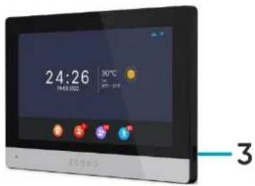
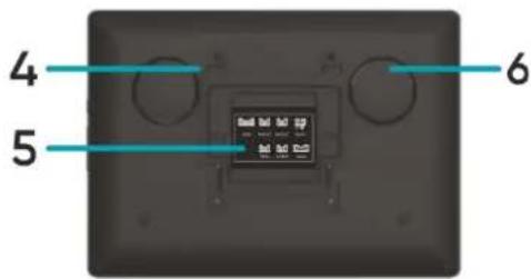
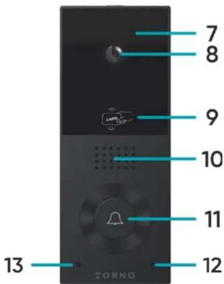
fig. 2 Construction of the outdoor unit with camera
MONITOR
- LCD touchscreen 4. Holes for mounting bracket
- Microphone 5. Connection terminals
- MicroSD card slot 6. Loudspeaker
OUTDOOR UNIT
- Night-time lighting 11. Call button/ status indicator
- Camera lens (blue: normal work, red: opening)
- RFID-tags/cards reader 12. Microphone
- Loudspeaker 13. Twilight sensor
5. INSTALLATION
MONITOR INSTALLATION
1,2
3,4

fig. 3 Monitor installation
- Drill holes in the wall and insert wall anchors into them.
- Screw the monitor mounting bracket to the wall with screws.
- Connect the wires to the monitor and hang it on the mounting bracket.
- Connect the power supply to the 230V AC outlet.
OUTDOOR UNIT WITH CAMERA INSTALLATION


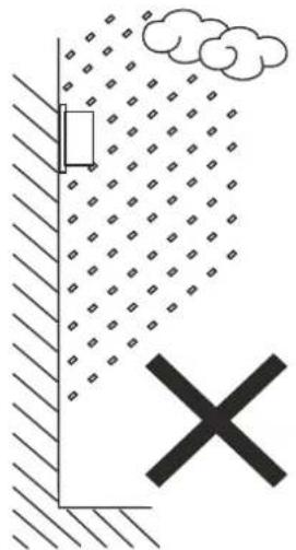
fig.4 Outdoor unit placement
Recommended installation height of the outdoor unit is 140-170cm.
The correct location of the outdoor unit determines the comfort of working with the device. It is recommended to test the device before making mounting holes. Do not place the outdoor unit and monitor in the same room as feedback may occur.
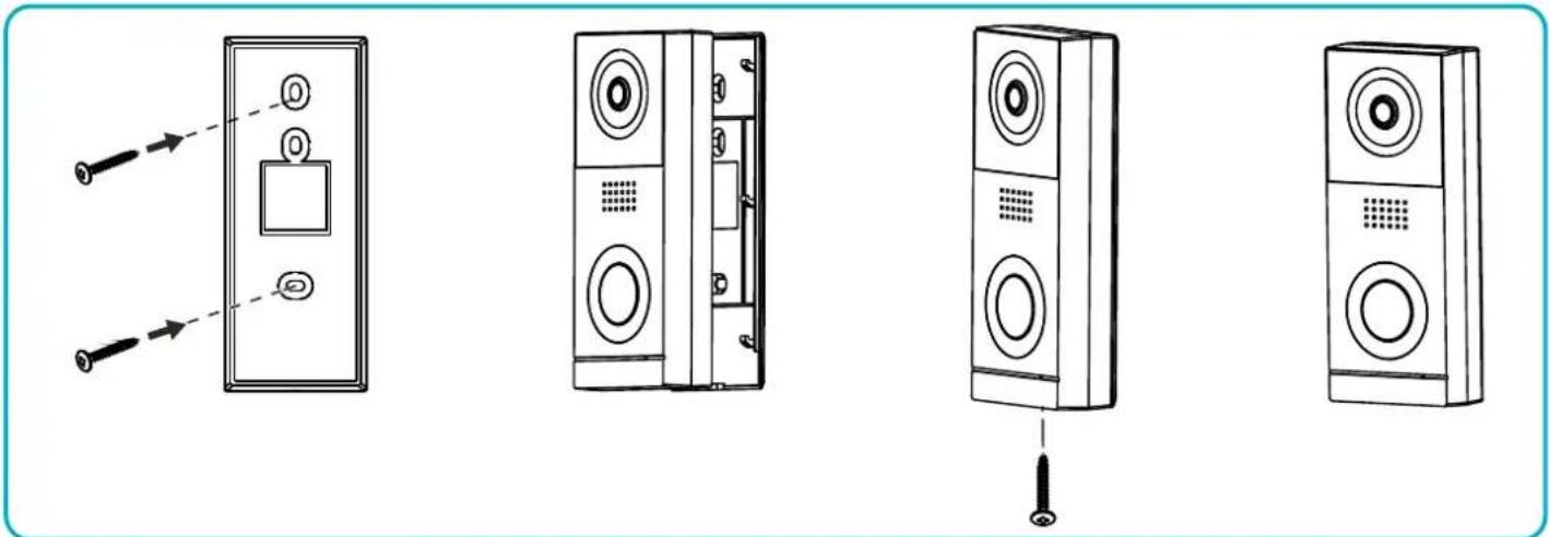
fig. 5 Outdoor unit with camera installation
- Drill holes in the wall and insert the wall anchors into them.
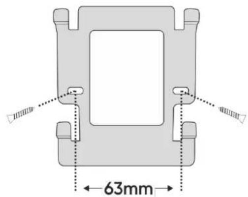
- Attach the mounting frame of the outdoor unit in desired place using screws.
- Connect the wires according to the wiring diagram.
- Place the outdoor unit in the mounting frame and secure it by screwing in the security screw from below.
6. WIRING DIAGRAMS

Before drilling the installation holes, it is recommended to carry out a functional test of the device. To do this, connect the device for a test according to the wiring diagram. The first person holding the camera should use the button to call the second person who is at the monitor. This person should then carefully inspect the camera's field of view in order to correct the module's position if necessary.
Once the measurements have been taken accurately, proceed with the mounting holes after switching off the power supply.
![graph TD A["Wi-Fi router"] --> B["IP camera 1"] A --> C["IP camera 2"] B --> D["main monitor (ID1)"] C --> E["main monitor (ID2)"] D --> F["24V DC power supply"] E --> G["24V DC power supply"] F --> H["24V DC power supply"] G --> I["24V DC power supply"] H --> J["24V DC power supply"] I --> K["24V D…](/content/2026/05/907120/images/a113724b88292592b7d05ed27700d46a65c82a46a5453b65f31cd89a1bffe8d3.jpg)
fig. 6 Wiring diagram
g. 7 Monitor and outdoor unit wiring diagram.
g. 8 Gate, electric door strike, and exit button wiring scheme.
It is forbidden to make connections to live equipment!
Failure to adhere to this recommendation may result in permanent damage to the device and loss of health.
The set does not include an electric door strike and automatic gate control unit!
The video doorphone cables should not be routed in one cable with the cables of other installations such as bell, alarm, etc. Any power and telecommunication cables emitting strong magnetic fields (e.g. loudspeaker columns, TV set) in direct contact with the cables connecting the outdoor unit to the monitor may adversely affect the operation of the set.
If the user has other connection cables than the recommended ones, it is allowed to use them, however, it is necessary to make a test connection of the set in order to check its correct functioning.
When designing the electrical installation, take into account the appropriate cable cross-section:
up to 30m - recommended cable XzTKMXpw 3 x 2 x 0,5mm
from 30m to 100m - recommended cable XzTKMXpw 3 x 2 x 0,8mm
The connection to the electromagnetic lock should be made with 2 x 1mm 2 cable.
The set is compatible with any electric door strike with 12V DC supply voltage and current consumption of max. 300 mA.
The total length of the installation must not exceed 100 meters.
We absolutely do not recommend the use of twisted-pair cables.
1 Intercom Intercom function available with additional monitors connected - tap to select the monitor you want to connect to.

1 Select the monitor you want to connect to,
2 Return to the previous page,
3 ID of the monitor you are connecting to,
4 ID of the monitor you are using,
5 Call button - tap to connect to the selected monitor.
| 2 | Monitoring | Tap to open the outdoor unit/IP camera view. |
| 3 | Event | Tap to check the record of calls, detected motion and stored photos. |
| 4 | Media | Tap to enter a folder with media files, including music, photos (requires a microSD card). |
| 5 | Settings | Tap to enter the settings menu. |
| 6 | Operating mode | Three possible settings: at home/ not at home/ sleep.At home: call and conversation available,Not at home: option of leaving a message by a visitor, sends a push notification on the phone when activity is detected,Sleep: monitor muted, sends a push notification on the phone when activity is detected. |
| 7 | Gate2 | Tap to open the gate (if the gate is connected). |
| 8 | Standby | Tap to enter standby mode. |
| 9 | Back | Tap to return to the previous page. |
OUTDOOR UNIT MONITORING
After tapping the Monitoring icon in the main menu or while connected to an outdoor unit, the outdoor camera view screen will be displayed. The maximum monitoring and call time is 30 seconds and the maximum call and conversation time is 120 seconds.

| 1 | Source | Indicates from which camera the view is displayed. |
| 2 | Date and time | Displays the current date and time. |
| 3 | Switch between cameras | Tap to change the camera view Door1/Camera1/Door2/Camera2. |
| 4 | Photo | Tap to save the image of the outdoor camera view (requires a microSD card). |
| 5 | Video | Tap to save the recording from the outdoor camera (requires a microSD card). |
| 6 | Gate opening | Tap to open the gate. |
| 7 | Door/wicket opening | Tap to release the electric door strike and open the door/wicket. |
| 8 | Settings | Tap to enter the settings menu:11 Adjust the brightness of the image,12 Adjust the volume of the monitor,13 Adjust the volume of the outdoor unit. |
| 9 | Answer the call | Tap to start a conversation (maximum conversation time is 120 seconds). |
| 10 | End the call | Tap to end the call and return to the main menu. |
IP CAMERA MONITORING
After switching to IP camera view, the image from the selected camera will be displayed. The maximum monitoring time is 30 seconds. During the monitoring, you can save a video recording (requires a microSD card). Note: this function is only available when an IP camera is connected.

| 1 | Source | Indicates from which camera the view is displayed. |
| 2 | Date and time | Displays the current date and time. |
| 3 | Switch between cameras | Tap to change the camera view Door1/Camera1/Door2/Camera2. |
| 4 | Photo | Tap to save the image of the outdoor camera view (requires a microSD card). |
| 5 | Video | Tap to save the recording from the outdoor camera (requires a microSD card). |
| 6 | Settings | Tap to enter the settings menu:11 Adjust the brightness of the image. |
| 7 | End monitoring | Tap to end monitoring and return to the main menu. |
RECORDINGS AND STORAGE
Important: Videos and photos cannot be saved and stored unless an SD memory card is installed in the device. To add a memory card, turn off the monitor, place the microSD memory card in the slot on the side of the monitor (maximum card capacity 128GB), and then turn on the monitor. It is also recommended to format the new SD card in the monitor settings (see page 18 Advanced settings).
-
All saved files can be viewed on a computer ([xxx.record] folder on the memory card).
-
Each file can be checked for date, recording time, source (from which camera the video/photo was recorded) and its format can be checked.
File name: YYYYMMDD-HHMMSS-ABC.AVI or JPG (year/month/day-hour/minute/second-)
Note: Meaning of the last three digits (marked ABC):
A: 1 - Door1 / 2 - Door2 / 3 - Camera1 / 4 - Camera2
B: 1 - MANUAL (manual recording) / 2 - AUTO / 3 - MOTION SENSOR / 4 - ALARM
C: 0 - photo / 1 - video recoring
Example:
File name: "20180109_045740_121.avi"
Video recorded automatically, triggered by visitors using the Call button on Door 1, on 9 January 2018, at 4:57:40.
CONNECTION AND CONVERSATION
- When the call/button on the outdoor unit is pressed, the monitor beeps and the image from the external camera is displayed on the screen. The ringing time is max. 30 seconds.
- When the answer call/button is tapped, the conversation can be started. The conversation time is max. 120 seconds. During the call, the door/gate can be opened.
- When another call comes in from the second outdoor unit, a new call will be started only when the current call ends.
- When the end call button is tapped, the conversation ends. The monitor returns to the main screen.
EVENT
After tapping the Eventicon in the main menu, a menu with three catalogues of registers will be displayed. Proper operation of the registers is possible only after adding a microSD memory card to the monitor.
![graph LR A["Call record"] --> B["Message record"] B --> C["Motion detection"] C --> D["End"]](/content/2026/05/907120/images/425c34977ce3e00696e5b682fdb6ed0177df370017f4c15c8a81deadab991535.jpg)
| 1 | Call record | A record of pictures/video recordings saved when the call button is pressed on the outdoor unit. |
| 2 | Motion detection | A record of pictures/video recordings saved when motion is detected by an outdoor un |
| 3 | Message record | A record of pictures/video recordings saved when the call button on the outdoor panel is pressed. Note: recording function available only in the not at home mode. |
| 4 | Back | Tap to return to the previous page. |
Tapping on the icon of the chosen catalogue opens the register of saved files. From this menu level, you can freely manage the files stored on the SD card.
![graph TD A["1 Call Record"] --> B["20191028085603.AVI"] B --> C["Open"] C --> D["Delete"] C --> E["Delete all"] C --> F["Close"] style A fill:#f9f,stroke:#333 style B fill:#ccf,stroke:#333 style C fill:#cff,stroke:#333 style D fill:#ffc,stroke:#333 style E fill:#cfc,stroke:#333 style F fill:#fcc,str…](/content/2026/05/907120/images/8b19266c94317c8ea599d950b7f523dd9ff29c0eafc9d5842c2fa5e097d829f1.jpg)
| 1 | File name | The name contains the date and time the file was saved (year/month/day-hour/minute/second-source/mode/format, see page 10 RECORDINGS AND MEMORY). |
| 2 | Register icon | Displays the icon of the selected catalogue. |
| 3 | Source | Displays the source from which the image/video recording was saved. |
| 4 | Actions | Tap the chosen file name to open the actions menu:Open - opens the selected file: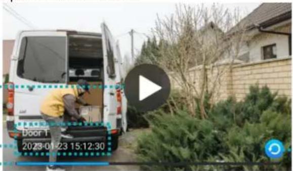 1...2...3...1 Play/Pause button (applies to video recordings only),2 Source - displays the date, time and source of the recorded image/video,3 Playback bar - displays the remaining time (applies to video recordings only),4 Back - tap to return to the previous page.Delete - deletes the selected file,Delete all - deletes all files in the open catalogue,Close - closes the action menu. 1...2...3...1 Play/Pause button (applies to video recordings only),2 Source - displays the date, time and source of the recorded image/video,3 Playback bar - displays the remaining time (applies to video recordings only),4 Back - tap to return to the previous page.Delete - deletes the selected file,Delete all - deletes all files in the open catalogue,Close - closes the action menu. |
| 5 | Back | Tap to return to the previous page. |
8. SETTINGS
SETTING MENU
After tapping the Settings icon in the main menu, the settings menu will be displayed. Tap another icon to move to the next setting category. After 30 seconds of inactivity, the screen will return to the main menu.
![graph TD A["1"] --> B["System"] C["2"] --> D["Door"] E["3"] --> F["Camera"] G["4"] --> H["Network"] I["5"] --> J["Scene"] K["6"] --> L["Advanced"] M["7"] --> N["System info"] O["8"] --> P["Feedback Loop"]](/content/2026/05/907120/images/5aaf40cbaebd55a35db9223e48ff3692f78e3e09412359fb708efd6051925f0e.jpg)
| 1 | System | Tap to enter the system settings. |
| 2 | Door | Tap to enter the outdoor unit settings. |
| 3 | Camera | Tap to enter the IP camera settings. |
| 4 | Network | Tap to enter the network settings and configure the device with Wi-Fi. |
| 5 | Scene | Tap to enter the digital frame settings. |
| 6 | Advanced | Tap to enter the advanced settings. |
| 7 | System info | Tap to open the system information tab. |
| 8 | Back | Tap to return to the previous page. |
SYSTEM SETTINGS
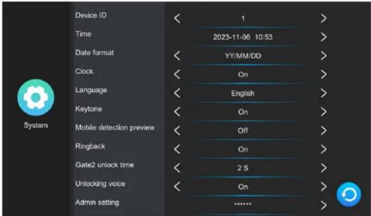
| Device ID | Displays the ID number of the current monitor. Number 1 is the default number of the main monitor, numbers 2-6 are the default numbers of additional monitors. |
| Time | Date and time configuration (the system automatically updates the date and tim information when connected to the phone). |
| Date format | Date format settings. |
| Clock | Enable or disable the clock function during standby mode. |
| Language | Language selection. Available languages: English, Polish, German, French, Portuguese, Spanish, Chinese, Italian, Hebrew, Japanese. |
| Keytone | Enable or disable touch sound. |
| Mobile detection preview | Enable or disable the external camera view function during detected motion. |
| Ringback | Enable or disable the doorbell sound on the outdoor unit. |
| Gate unlock time | Opening time settings for Gate 2 (which is directly connected with the monitor). |
| Unlocking voice | Enable or disable the voice response from the outdoor panel when the door or gate is opened (available in English only). |
| Admin setting | Enter the administrator settings by entering the administrator password (default: 888888). |
ADMINISTRATOR SETTINGS

| Room number | Setup the room number of the selected monitor (applies to multifamily models). |
| Router address | Displays the IP address of the device. |
| Change password | Tap to change the administrator password. |
| Card manage | Tap to open the configuration menu for proximity cards and tags. |
| Password management | Tap to open the configuration menu for access passwords that allow to open the door from the level of the outdoor unit (does not apply to OR-VID-MA-1079 model). |
PROXIMITY CARDS AND TAGS MANAGEMENT
After tapping on the Card manage option in the administrator settings menu, the proximity card and tag settings menu will be displayed.

| 1 | Door | Select Door1/Door2 to edit the accesses of the selected outdoor unit. |
| 2 | Add | Tap to add a new proximity card or tag and then place the card/tag close to the RFID reader on the outdoor unit.You can add multiple proximity cards/tags at once by bringing them close to the reader one by one. Each correct addition will be indicated by a short beep. Tap back to return to the cards and tags settings menu - all added cards/tags will be displayed on the list |
| 3 | Access | Select what can be opened by the selected proximity card/tag (lock - releases the electric strike, gate1 - controls the opening/closing of the gate). |
| 4 | Actions | Tap the chosen card number to open the actions menu:Delete- removes the selected proximity card/tag, Delete all- removes all proximity cards/tags, Close- closes the actions menu. |
| 5 | Back | Tap to return to the previous page. |
OUTDOOR UNIT SETTINGS
After tapping the Door icon in the settings menu, the outdoor unit settings menu will be displayed.
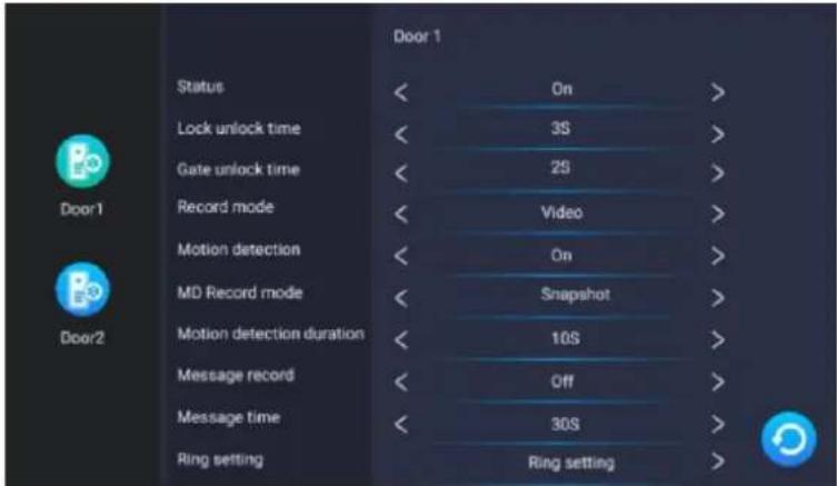
| Status | Turn the outdoor unit on or off from the level of the monitor. |
| Lock unlock time | Door/wicket opening settings (1-10s). |
| Gate unlock time | Gate opening settings (1-10s). |
| Record mode | Incoming call recording format settings (photo/video recording). |
| Motion detection | Enable or disable motion detection function (works only with digital frame off). |
| MD record mode | Motion detection file saving format settings (photo/video recording). |
| Motion detection duration | Motion detection time settings. |
| Message record | Enable or disable the visitor's message function. |
| Message time | Settings for the maximum length of a message left by a visitor. |
| Ring setting | Melody and volume of the ringtone settings. |
IP CAMERA SETTINGS
After tapping the Cameraicon in the settings menu, the IP camera settings menu will be displayed. To configure an IP camera, go to section 9. IP CAMERA CONNECTION.
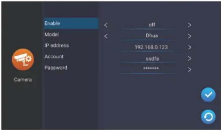
| Enable | Turn the IP camera on or off from the level of the monitor. |
| Model | Select the model of your IP camera to complete the configuration. |
| IP address | Enter the IP camera's IP number to complete the configuration. |
| Account | Enter the account number (login) of your IP camera. |
| Password | Enter the IP camera's password. |
NETWORK SETTINGS
After tapping the Network icon in the settings menu, the network settings menu will be displayed. From this level you can connect your device to a Wi-Fi network.

| Net pairing mode | Select the device's Wi-Fi connection mode: EZ mode – wireless Wi-Fi connection, Cable* – wired connection using Cat.5a cable. |
| WLAN | Connect to a Wi-Fi network. The device automatically searches for the nearest Wi-Fi networks – select your network and enter the password to connect the device to the Internet. If the device does not detect a Wi-Fi network, you can add one manually by entering the network's IP and password. |
| Network information | Display the information of the network to which the device is connected. |
| QR code | Display the QR code to download the Tuya Smart mobile app. |
* To use the Tuya Smart app with a wired connection:
- Connect the monitor to your Wi-Fi router with a Cat.5a cable.
- Then in the network settings, change the connection mode from EZ mode to Cable.
- Change the network connection category from statically assigned to dynamically assigned.
- After changing the category, press back and the monitor will display a system reboot window.
- Allow the system to reboot and wait for the monitor to restart.
- After restarting the system, enter the network settings again and open the QR Code tab to display the QR code that allows to connect the set with the mobile app.
DIGITAL FRAME SETTINGS
After tapping the Scene icon in the settings menu, the digital frame settings menu will be displayed. In order to use all digital frame features, photos must be placed on the SD card in the picture folder, while music must be placed in the music folder.

| Digital photo | Enable or disable digital frame function (function active only in standby mode and with motion detection disabled). |
| Digital photo switch time | Photo display time settings. |
| Background music | Enable or disable the background music function when the digital frame is displayed. |
| Background music volume | Background music volume settings. |
ADVANCED SETTINGS
After tapping the Advanced icon in the settings menu, the advanced settings menu will be displayed.

| Format SD card | Tap to format the SD card. After adding a new SD card to the device, it is recommended to format it before further use. |
| Indoor monitor reset | Tap to restore the factory settings of the monitor. Be sure to remove the device from the Tuya app as well before doing this, otherwise the device cannot be added and used by other accounts.Note: if you return or refer the device for service repair, you must remove the device from the Tuya Smart app and restore it to factory settings! |
| Door station reset | Tap to restore the factory settings of the outdoor unit. |
| Admin reset | Tap to restore the default administrator password. |
| Door station upgrade | Tap to update the outdoor unit software (make sure the software has been copied to the SD card before updating). |
| Restart system | Tap to reboot the system. |
| App open lock | Tap to configure accesses from the mobile app (select Gate1 - unlock from the outdoor panel and Gate2 – unlock from the monitor). |
SYSTEM INFORMATION
After tapping the System info icon in the settings menu, the system information tab will be displayed. Here you will find information about the system and software version, update date, used and total memory of the microSD card as well as the login ID for the Tuya Smart app.
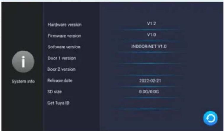
9. IP CAMERA CONNECTION WIRED CONNECTION
Note: make sure the IP camera you want to connect supports the ONVIF protocol.
- Connect the IP camera to the router using a Cat.5e network cable, and then connect the computer to the same router. Make sure the camera and the computer are on the same subnet.
- Download and install the dedicated camera application to activate the IP camera. Refer to the manual of your chosen IP camera for installation details. Note: after activation, remember the camera's IP address, password and administrator name.
- open the camera's configuration panel by typing the IP number of the camera in the browser window and confirming with the administrator password. In the configuration panel, enable the ONFIV protocol and set the video transmission settings to 1920*1080 @ H.264. Note: the video doorphone system supports the transmission of maximum resolution of 1080P/2MP.
- After configuring the IP camera, make sure the monitor is connected to the Wi-Fi network and is on the same subnet as the IP camera.
![graph LR A["main monitor"] --> B["router Wi-Fi 2.4G"] B --> C["IP camera"] C --> D["power supply"]](/content/2026/05/907120/images/e0519b3639a484b3a5086b463dda63f26759fe586455362fbded6c736997b0d6.jpg)
fig. 9 Connection scheme for the monitor and wired IP camera.
-
On the monitor in the main menu, select Settings and then Camera to display IP camera settings. The monitor will automatically start searching for the camera. If the camera supports the ONFIV protocol, its IP address will be displayed on the monitor:
-
Tap on the IP address of the camera to open the configuration menu. Fill in the administrator's name and password to complete the camera configuration.


WIRELESS CONNECTION
Note: make sure the IP camera you want to connect supports the ONVIF protocol and has the function of wireless connection via Wi-Fi.
- Configure the wireless IP camera according to the instructions of the chosen camera. Be sure to enable the ONFIV protocol in the configuration panel.
- Install the dedicated IP camera app on your phone and complete the configuration.
- connect all devices to the Wi-Fi network. Make sure that the camera, the monitor, and the phone with the camera app installed are on the same subnet.
![graph LR A["main monitor"] --> B["router Wi-Fi 2.4G"] B --> C["wireless IP camera"] C --> D["power supply"]](/content/2026/05/907120/images/37ad49a41e3fb37aa72cb8a8cd3521f4505f40e7294cc9fc83e155ae66021215.jpg)
fig. 10 Connection scheme for the monitor and wireless IP camera.
-
On the monitor in the main menu, select Settings and then Camera to display IP camera settings. The monitor will automatically start searching for the camera. If the camera supports the ONFIV protocol, its IP address will be displayed on the monitor:
-
Tap on the IP address of the camera to open the configuration menu. Fill in the administrator's name and password to complete the camera configuration.
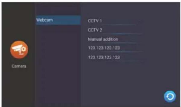

10. MOBILE APP INSTALATION
LOGIN
Note: a device can only be paired with one Tuya account. To pair the device with a new account, remove the pairing with the previous account or use the share function in the app to make the device available for a second account.
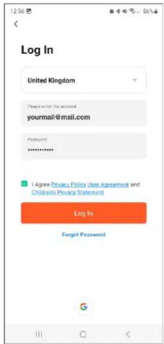
- Open the App Store (iOS) or Google Play (Android) on your phone. Search for the app "Tuya Smart" and install it or scan the QR code.

- If you do not already have an account in the app, click Sign up, you will be redirected to the next page. The system will automatically identify the country/region you are from or you can manually select it yourself. Enter your e-mail address, check your agreement with the privacy policy and click onReceive verification code Enter the code you received, then enter your password and click Go to app.

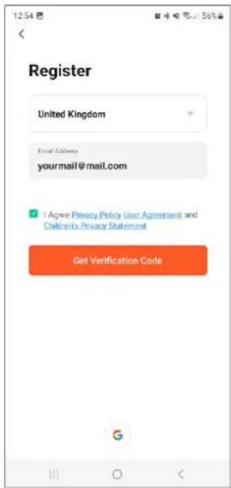
PAIRING THE DEVICE WITH THE PHONE
- Connect the monitor to a Wi-Fi network. To do this, go toSettings>Network and then select EZ mode and connect the monitor with the desired Wi-Fi network. Once connected to the Wi-Fi network, select the QR code tab and scan it to connect the monitor with the app. Note: make sure your phone and the monitor are connected to the same Wi-Fi network.

- In the app on your phone, click Add device and then click the Scan icon located in the upper right corner. Scan the QR code displayed on the monitor to start the process of pairing the device with your phone.


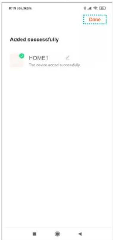
- Be patient, the pairing process can take about 60 seconds. When it's finished, try to go to the external camera view to check if the connection is correct.


INVITING USERS
-
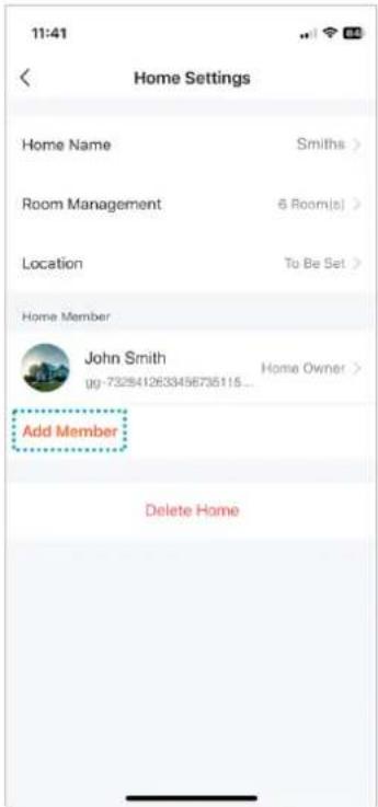
Select the Metab on the bottom bar of the app, then enter Home management>My Home. Here, give the family a name (e.g. the Smiths).
-
Select Add members On the app screen, options of sharing the invitation code will appear (e.g. text message). Invited users can add their device by entering the invitation code in Home management>Join a home- once the app is installed.
Note: the device can be shared with up to 20 people, including the administrator.


Note: in case the device is returned or sent for service repair, the device must be restored to factory settings and removed from the application.
Note: to ensure the correct functioning of the application, the user is obliged to update the application in accordance with communications from the application operator.
11. CLEANING AND MAINTENANCE
- The monitor should not be placed in a location exposed to high temperatures, in direct sunlight or high humidity locations (e.g. bathrooms),
- the monitor should not be placed near a television set or other objects that may cause interference to the signal,
- do not touch the device with wet hands,
- clean the camera lens with a dry cloth, do not use chemical cleaners,
- do not place the camera in direct sunlight,
- before installing the device in the chosen place, make sure that there is no signal interference,
- avoid switching off the device during recording, data may be lost.
12. TROUBLESHOOTING
1. No audio/video, no indicator light
a) no supply voltage,
b) damaged or incorrectly connected connecting cable, check your installation for technical requirements page 4-5,
c) check that the installation is not exposed to water, moisture etc.,
d) check that the camera lens is not obstructed by an object that prevents proper view.
2. No video but audio is normal
a) check that all connections are made correctly with regard to technical requirements,
b) check that the camera lens is not obstructed by an object that prevents proper view.
3. No audio when calling
a) ensure that the monitor volume is not set to the lowest setting,
b) ensure that there are no objects in the vicinity of the device that could cause interfering with the signal,
c) check that all connections are made correctly with regard to technical requirements.
4. Outdoor unit cannot call the monitor
a) check that all connections are made correctly with regard to technical requirements.
5. Electric door strike not working
a) check the independent operation of the electric door strike by connecting it to the required voltage, etc.
6. Cannot hear the visitor when answering a call
a) press the 📞 button to activate two-way intercom,
b) check that all connections are made correctly with regard to technical requirements.
7. You can hear the visitor when you receive a call, but you cannot answer them
a) press the 📊 button to activate two-way intercom (pressing the 🔒 button on the monitor, the outdoor unit cannot hear the indoor unit),
b) check that all connections are made correctly with regard to technical requirements.

INHALTSVERZEICHNIS
- VORBEMERKUNGEN .... 3
- MERKMALE 4
- TECHNISCHE DATEN 4
- KONSTRUKTION DES SETS .... 5
- MONTAGE 6
MONTAGE DES MONITORS....6
MONTAGE AUßENSTATION ....6
- ANSCHLUSSPLAN....7
- BETRIEB DES GERÄTS....9


KOPPLUNG DES GERÄTS MIT EINEM TELEFON



- SPIS TREŚCI
- OPERATING AND INSTALLATION INSTRUCTIONS
- TABLE OF CONTENTS
- SAFETY INSTRUCTIONS
- CHARACTERISTICS OF THE SET
- FUNCTIONS
- KEY FEATURES
- TECHNICAL DATA
- OUTDOOR UNIT
- SET CONSTRUCTION
- MONITOR
- INSTALLATION
- MONITOR INSTALLATION
- OUTDOOR UNIT WITH CAMERA INSTALLATION
- WIRING DIAGRAMS
- OUTDOOR UNIT MONITORING
- IP CAMERA MONITORING
- RECORDINGS AND STORAGE
- CONNECTION AND CONVERSATION
- EVENT
- SETTINGS
- SETTING MENU
- PROXIMITY CARDS AND TAGS MANAGEMENT
- OUTDOOR UNIT SETTINGS
- IP CAMERA SETTINGS
- NETWORK SETTINGS
- DIGITAL FRAME SETTINGS
- ADVANCED SETTINGS
- SYSTEM INFORMATION
- IP CAMERA CONNECTION WIRED CONNECTION
- WIRELESS CONNECTION
- MOBILE APP INSTALATION
- LOGIN
- PAIRING THE DEVICE WITH THE PHONE
- INVITING USERS
- CLEANING AND MAINTENANCE
- TROUBLESHOOTING
- NO AUDIO/VIDEO, NO INDICATOR LIGHT
- NO VIDEO BUT AUDIO IS NORMAL
- NO AUDIO WHEN CALLING
- OUTDOOR UNIT CANNOT CALL THE MONITOR
- ELECTRIC DOOR STRIKE NOT WORKING
- CANNOT HEAR THE VISITOR WHEN ANSWERING A CALL
- YOU CAN HEAR THE VISITOR WHEN YOU RECEIVE A CALL, BUT YOU CANNOT ANSWER THEM
- INHALTSVERZEICHNIS
- KOPPLUNG DES GERÄTS MIT EINEM TELEFON
Brand : VIBELL
Model : OR-VID-MA-1079
Category : Doorbell