21476 - Pregnant K&M - Free user manual and instructions
Find the device manual for free 21476 K&M in PDF.


| Product Type | Speaker Stand |
| Brand | K&M |
| Model | 21476 |
| Maximum Load Capacity | 50 kg (centric load) |
| Height Range | 1420 - 2200 mm |
| Base Circle Diameter | 1150 mm |
| Expanding Mandrel Diameter | 35 - 36.5 mm |
| Net Weight | 6.2 kg |
| Packing Size | 1162 x 120 x 130 mm |
| Material | Steel (base, feet, extension tubes), Aluminum (tension ring), PA (clamps, handles, mandrel elements), TPE (parquet protectors, dampener) |
| Clamping System | Patented expanding mandrel system; locking bolt and clamping screw for height adjustment |
| Safety Features | Requires two persons for height adjustment under load; visual inspection before and after use; never loosen locking bolt uncontrollably |
| Maintenance | Clean with damp cloth and non-abrasive cleaner; no lubrication required; inspect for damage regularly |
| Repairability | Loose components (e.g., parquet protectors, clamping screws) replaceable on site; structural repairs by qualified personnel or manufacturer |
| Compatibility | PA speakers with bushing ø 35 mm (e.g., Teufel ROCKSTER AIR); adapter sleeve 21326 for US bushings (ø 38 mm) |
| Accessories (Optional) | Carrying case 21311, flange adapter 19654/19656, mounting adapter 19580/24281, warning strip 21402, leveling leg 21445, adapter sleeve 21326 |
| Environmental Protection | Store in a dry place; protect from moisture and humidity |
Frequently Asked Questions - 21476 K&M
User questions about 21476 K&M
0 question about this device. Answer the ones you know or ask your own.
Ask a new question about this device
Download the instructions for your Pregnant in PDF format for free! Find your manual 21476 - K&M and take your electronic device back in hand. On this page are published all the documents necessary for the use of your device. 21476 by K&M.
USER MANUAL 21476 K&M
natural_image
Technical line drawing of a tripod-mounted device with a circular light source and a cylindrical device attached (no text or symbols)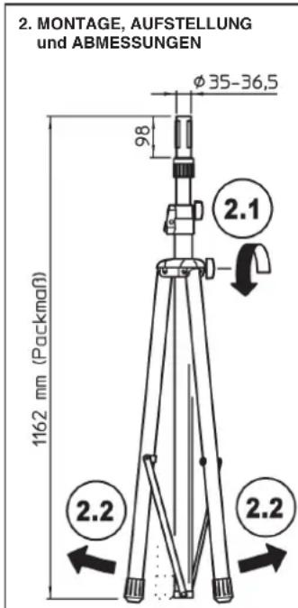
F: STATIV WACKELT ODER STEHT SCHIEF
- Stand with a manually adjustable extension for PA speakers, e.g. the Teufel ROCKSTER AIR
FEATURES & CAPABILITIES
- A patented expanding mandrel system provides a tight an firm fit for the speaker
- Professional quality. sturdy, stable and foldable to save space
- Suitable for rehearsal room, studio, stage, tour - and party room
- Maximum load-bearing capacity: 50 kg*
- Height 1420 - 2200 mm, base circle ø 1150 mm, expanding mandrel system: ø 35-36.5 mm weight 6.2 kg
Thank you for choosing this product. Please read and follow carefully the instructions. They inform you about all important steps, that are required for a safe assembly and operation. Please keep the instructions for future reference.
SAFETY INSTRUCTIONS (summary)
Please see the attached sheet for precise details.
A. GENERAL
- The maximum centric load-bearing capacity adds up to 50 kg*
- Load capacity is a suitable PA with bushing ø 35 mm (e.g. Teufel ROCKSTER AIR)
- Ensure that the floor is suitable, i.e. level and loadbearing
- Works should be carried out by competent staff (technical and physical)
- The safety of operation is based, among other things, on the observance of these operating instructions, especially the points mentioned here under A-G.
B. NOTICE of "FORESEEABLE MISAPPLICATION"
- Base and extension tube combination must always be installed vertically (not inclined!)
- Do not load the stand on one side, as this reduces the stability or load-bearing capacity
- It is not allowed to shift the stand, especially under load
- Protect the stand from moisture and humidity
C. BEFORE USE
- Visually inspect the stand - do not use damaged stands
D. ASSEMBLING THE STAND
- For maximum stability, set the largest possible root diameter
- Tighten the clamping screws firmly, but without using any tools. Hand tight is completely sufficient
- The locking bolt 4.5 for fixing the extension tube must always be engaged
- except when adjusting the height
E. EXTENDING/RETRACTING THE LOAD (see chapter 4)
- These activities must always be carried out by at least two suitable persons
- The "first person" has to hold the extension tube with bearing load firmly and securely, while the "second person" can use the securing elements locking bolt and clamping screw at any time. e.g. if the "first person" is not able to hold the tube and the load.
F. DURING USE - Safety during operation is based on:
- Never loosen locking bolt 4.3 and clamping screw 4.2 of the extension tube in an uncontrolled manner
- CONTROL of LATERAL FORCES (relevant due to danger of tipping) Lateral forces must be avoided. These occur when:
a. the stand is inclined
b. the load balance is exocentric
c. external shocks such as kicks, pulling on the stand, vibrations, wind, etc. are suffered)
G. AFTER USE
- Allow the load to retract slowly and in a controlled manner (see above - E)
- Carry out visual inspection (see above - C)
- Carefully fold up the stand and stow it away in a protected place
TECHNICAL DATA
| Material | Base, foot, extension tubes: SteelStruts, screws, rivets: SteelTension ring: AluminumClamps, handles, mandrel elements: PAParquet protectors, dampener: TPE | Load max. 50 kg* | |
| Pull-out expanding mandrel syst.: ø 35-36,5 | |||
| Box 1200 x | 45 x 60 mm | ||
| Accessories (optional) | Carrying case 21311Flange adapter (19654, 19656)Mounting adapter (19580, 24281)Warning strip 21402Leveling leg 21445Adapter Sleeve 21326: ø 38 mm | ||
| Dimen-sions | Max. base circle: ø 1150 mmHeight: min. 1420 - max. 2200 mmPacking size: 1162 x 120 x 130 mmNet weight: 6.2 kg | ||
INSTALLATION - / USER INSTRUCTIONS
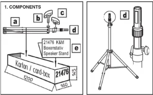
1. COMPONENTS
After unpacking, visually inspect whether all parts are present and - if identifiable - whether they are in order:
a Stand, folded,
b Clamping screw (M8 x 23 mm) for triangular clamp
c Clamping handle (M8 internal thread) of the telescopic bolt clamp
d Extension tube with »Ring Lock« mechanism
e Instruction manual
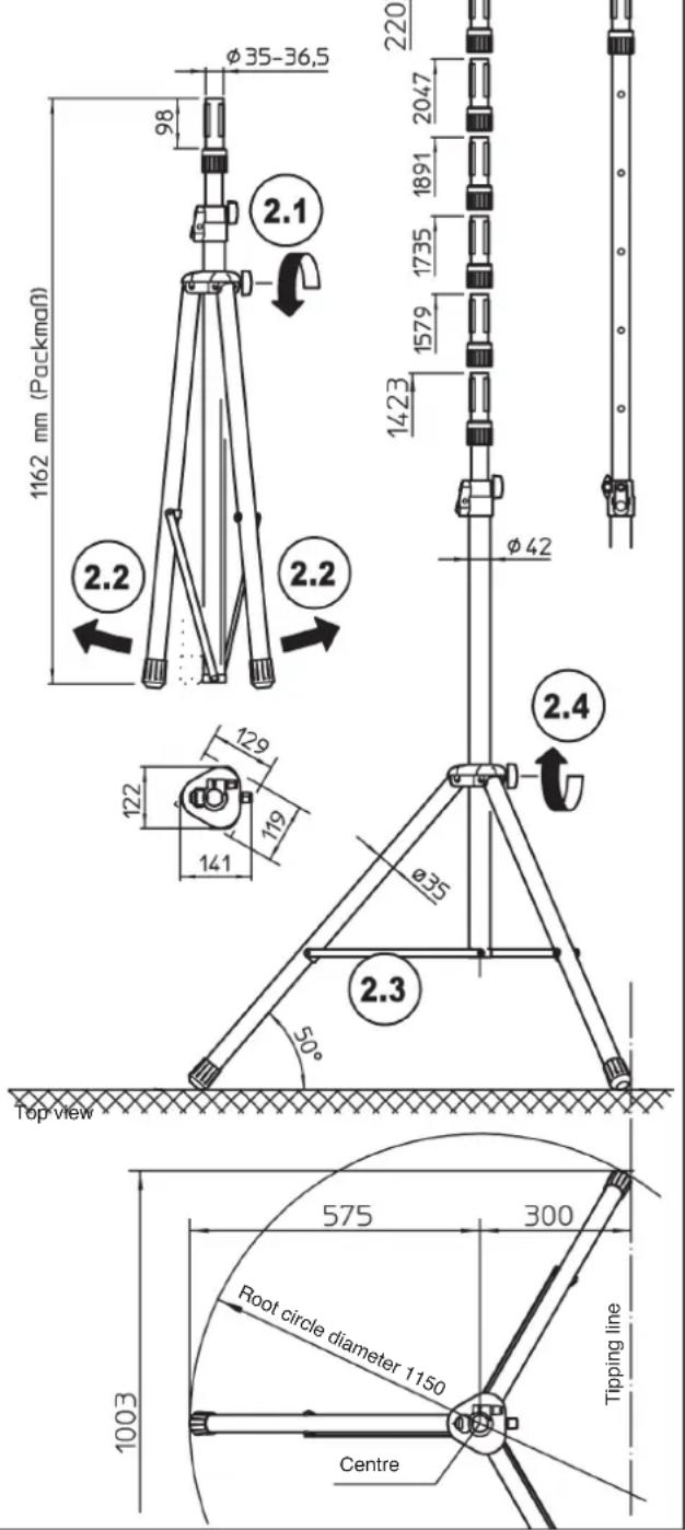
2. ASSEMBLY, DIMENSIONS
The 21471 stand is completely pre-assembled ex factory. For installation proceed as follows:
2.1 Loosen slightly the clamping screw b of the triangular clamp.
2.2 Preferably, pull the legs apart simultaneously until.
2.3 ...the connecting struts are horizontal (= maximum root diameter)
2.4 Tighten clamping screw b again - manual force is sufficient.
NOTE: Avoid overtightening - it strains the components.
- ASSEMBLY, DIMENSIONS
USER INSTRUCTIONS / FUNCTIONS
ATTACHING and EXTENDING THE LOAD
WARNING!
Do not underestimate the weight of the speaker:
- When placing the speaker and extending or retracting the tube, be sure to employ technically and physically suitable personnel.
- Hold the extension tube with a firm grip during height adjustment 4.1 and always secure the chosen final position with the locking bolt 4.5.
3. ATTACHING THE SPEAKER TO THE STAND
3.1 Turn expanding mandrel clamping sleeve to the right (direction OPEN), to set the smallest diameter.
3.2 Place the speaker on the expanding mandrel.
3.3 Now turn the clamping sleeve to the left (direction CLOSE) until...
3.4 ...the expanding mandrels fit firmly.
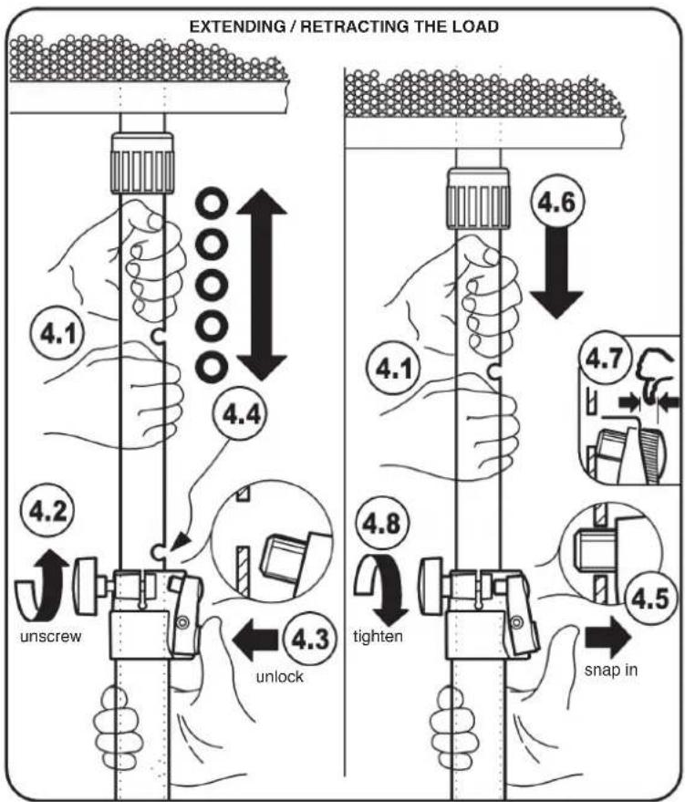
4. EXTENDING/RETRACTING THE LOAD
Involved parties:
FIRST PERSON: (in case of heavy loads, several persons if necessary): - operates the extension tube with the load 4.1, 4.4, 4.6
SECOND PERSON: - attends to the clamp
a. the clamping screw 4.2, 4.8 and
b. the locking bolt 4.3, 4.5, 4.7
ATTENTION!
If FIRST PERSON can no longer hold securely the loaded extension
tube, then the SECOND PERSON should:
a. immediately tighten the clamping screw 4.8,
b. releases the locking bolt 4.5 and ensure that the bolt engages automatically in the nearest borehole.
EXTENDING THE LOAD
FIRST PERSON
4.1 holds the loaded extension tube tightly with both hands. Does not cover the boreholes.
SECOND PERSON
4.2 loosens the clamping screw and holds it and...
4.3 ...then presses the push button until the locking bolt no longer engaged in the extension tube
FIRST PERSON
4.4 lifts the extension tube together with the load into the approximately chosen height; NOTE: In order to find the chosen borehole easily, the bore should find itself in this very moment just above the clamp
SECOND PERSON
4.5 releases the push button, so that the locking bolt automatically snaps into the extension tube.
FIRST PERSON
4.6 lowers the extension tube slowly until the locking bolt engages in the intended hole
SECOND PERSON
4.7 ensures that the locking bolt is engaged as far as it goes (= no protrusion is allowed)
4.8 tightens the clamping screw
RETRACTING THE LOAD
FIRST PERSON
4.1 holds the loaded extension tube with both hands, without covering the boreholes.
SECOND PERSON
4.2 loosens slightly the clamping screw and...
4.3 ...pushes the button and holds it (the locking bolt is unlocked)
FIRST PERSON
4.6 lowers the extension tube slowly and controlled
SECOND PERSON
4.8 measures the clamp force of the screw so that the extension tube, due to the friction in the clamp, retracts slowly and not suddenly and uncontrolled
FIRST PERSON
4.6 whilst still holding the extension tube tightly, to ensure the controlled retracting of the load. This needs to be carried out until the desired height is reached or until the tube is completely retracted.
SECOND PERSON
4.5 releases the push button, so that the latching pin will automatically snap into the extension tube
4.7 ensures that locking bolts engaged as far as it will go (= no protrusion allowed)
4.8 tightens the clamping screw
Accessories - Application examples (not included) - only for extension 0.35 mm
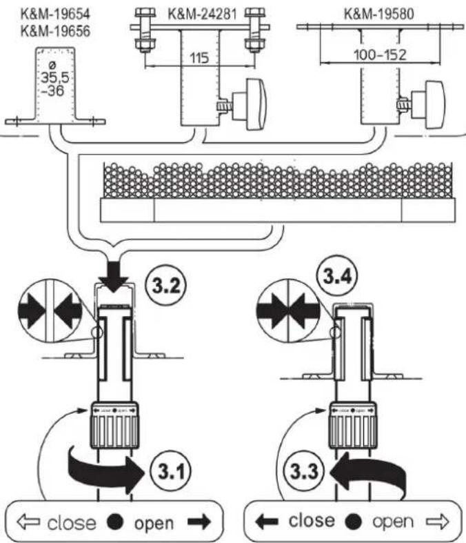
flowchart
graph TD
    A["K&M-19654 K&M-19656"] --> B["35.5 -36"]
    B --> C["Valve 1"]
    D["K&M-24281"] --> E["115"]
    F["K&M-19580"] --> G["100-152"]
    G --> H["Valve 2"]
    I["3.2"] --> J["Valve 3"]
    K["3.4"] --> L["Valve 4"]
    M["3.3"] --> N["Valve 5"]
    O["← close ● open →"] --> P["← close ● open →"]
FAULT-FINDING (F) and REPAIR (R)
See the ATTACHED SHEET
MAINTENANCE
See the ATTACHED SHEET
SUPPLEMENTAL SHEET
to instruction manual
21476-000-55 Speaker stand » Ring Lock«
COMPLETE VERSION of the relevant instruction summary
SAFETY INSTRUCTIONS
Numbers marked with *, e.g. *14, refer to reference numbers in the diagram of the instruction manual
A. GENERAL
- The maximum centric load-bearing capacity adds up to 50 kg*
- Load capacity is a suitable PA with bushing ø 35 mm (e.g. Teufel ROCKSTER AIR)
- Make sure that the floor is suitable, i.e. level and loadbearing. The foot of the stand should not slide or sink, regardless if it is loaded or not.
- If the floor is uneven (or steps), suitable measures must be taken to ensure vertical position of the support tube, e.g. by using the K&M compensation adapter 21445 (optionally available).
- Use sufficient personnel (if necessary two or more technically and physically suitable persons).
- Unauthorized persons must keep and maintain distance to the loaded stand.
- There is risk of tripping, if the safety distances are not observed. The danger can be minimized by using the eye-catching warning strip 21402 (optionally available).
- Careful handling is required, as the adjustment possibilities hide the risk of entrapment.
- The safety of operation is based, among other things, on the observance of these operating instructions, especially the points mentioned here under A-G.
B. NOTICE of "FORESEEABLE MISAPPLICATION"
- The mounting position of the base/extension tube combination should be vertical and not inclined. Possible causes for misalignment are: unsuitable floors, one-sided load, defective stand.
- Do not load the stand on one side (eccentric loading impairs stability of the installation respectively reduces the max. load-bearing capacity).
- ATTENTION: It is not allowed to shift the stand, especially under load, as this may lead to severe hazards (tip over hazard, damage to components).
- Protect the stand from moisture and humidity.
C. BEFORE USE
- First of all, visually check whether the stand is complete and, if so, whether it is all right. Damaged stands must not be used - or only after qualified repair.
- Loads and aids (e.g. ladders) must also be checked for suitability.
D. SETTING UP THE STAND
- First check the function and movability of the stand and its components in unloaded condition.
- Observe the information as mentioned in the chapter 2. ASSEMBLY INSTRUCTIONS.
- For maximum stability set the largest possible root diameter. This condition is given when the position of the bracing is horizontal. WARNING: A bracing that is not completely opened may save space but jeopardises severely the stability.
- Tighten the clamping screws *2.4 / *4.8 without using tools. Manual force is sufficient, especially since overtightening puts a strain on the components.
- When the height adjustment is completed, the locking bolt *4.5 should always be engaged and the clamping screw *4.8 should be tightened.
E. EXTENDING/RETRACTING THE LOAD (see chapter 4)
- These activities must always be carried out by at least two suitable persons
- The "first person" has to hold the extension tube with bearing load firmly and securely, while the "second person" can use the securing elements locking bolt and clamping screw at any time, e.g. if the "first person" is not able to hold the tube and the load.
F. DURING USE
- Never loosen uncontrolled the locking pin *4.3 and the clamping screw *4.2 of the extension tube. Rather, the procedure described in Chapter E. (see above) must be followed.
- CONTROL OF LATERAL FORCES (due to tipping hazard).
Lateral forces must be avoided at all costs. They occur when:
a. the stand is inclined: - measures: ensure a level flooring, use K&M 21445 compensation adapter
b. eccentric balance of the load:
- measures: allow only marginal deviation
c. external shocks (jolts, pulling on the stand, vibrations, wind, etc.):
- measures: ensure that the safety distances are observed and keep out unauthorized persons
If these requirements cannot be met, the installer must provide further measures to ensure the safety of the installation.
Examples:
- stabilize the stand with ropes, reduce load and height, change position.
G. AFTER USE
- Retract the load slowly and in a controlled manner. Please observe chapter E. (see above) and the procedure described in chapter 4 of the ASSEMBLY INSTRUCTIONS.
- Perform another visual inspection to ensure that the stand is complete and, as far as can be seen, in good working order. Damaged stands must be subject to qualified repair before further use.
- First remove the speaker, then fold up the stand carefully and store it in a safe place.
SUPPLEMENTAL SHEET
to instruction manual
21476-000-55 Speaker stand » Ring Lock«
COMPLETE VERSION of the relevant instruction summary
MAINTENANCE:
CHECKING, MAINTENANCE, CLEANING
OBJECTIVE
of maintenance is to maintain the smooth mobility, load capacity and safety of the stand over a longer period of time. This is achieved by:
a. careful handling,
b. removing dirt, moisture, corrosion,
c. replacement or repair of defective parts - without any special knowledge
MAINTENANCE STAFF
According to DGUV (German general public accident insurance) standards 315-390 (former BGG/GUV-912 chap. 4 Qualifications) maintenance personnel should have at least the qualification of an instructed person.
This person can: - detect external damage and wear, - carry out visual and functional checks,
- recognize safe operating condition and the functionality of the protective devices.
MEASURES
- Perform a visual inspection before and again after use. Is the stand:
- functional (workable, not worn out, vertical standing, screws and locking bolts are intact),
- complete (clamping handles, parquet protectors, rivets):
- as far as visible undamaged (deformed tubes and struts, chipped off clamps, worn out rivets)
Damaged stands must not be used or only after a qualified repair.
- Loose components (e.g. parquet protectors, clamping screws) can be replaced on site. Repairs or the replacement of inseparably connected parts (tubes, clamps, rivets, struts) must be carried out by qualified local personnel or at the manufacturer's premises (K&M).
- Care and maintenance work must always be carried out in an unloaded condition
- Possible hazards during maintenance work are crushing when folding the tubes. In order to avoid this, it is necessary to handle them with care.
Use protective gloves if necessary.
- Use a slightly damp cloth and a non-abrasive cleaning agent for cleaning
- Other measures such as periodic lubrication, etc. are not necessary.
FAULT-FINDING (F) and REPAIR (R)
F: STAND WOBBLIES OR IS CROOKED
R: If the floor is not suitable (unstable, uneven), restore or change location
R: If necessary, compensate sloping ground by using leveling leg 21445
R: Replace missing or damaged parquet protectors with original parts
R: Pull feet apart as far as possible (= horizontal struts *2.3)
R: Reduce eccentric load effectively
R: Stop negative external influences (wind, vibrations) or compensate them by additional measures (rope stretching)
F: EXTENSION TUBE WOBBLES OR RETRACTS UNDER LOAD
R: Ensure that the locking bolt *4.5 is engaged
R: Tighten the clamping screws *2.4, 4.8
F: SPEAKER TEETERS ON THE EXPANDING MANDREL SYSTEM
R: Re-tighten the ring lock *3.3
R: Check speaker bushes (max. ø 36 mm)
B: For US speaker bushes (ø 38 mm) always use adapter sleeve 21326
F: SPEAKER IS DIFFICULT TO ADJUST
R: Lift the speaker up a bit during the adjustment
R: Loosen ring lock *3.1 a little more

- FEATURES & CAPABILITIES
- SAFETY INSTRUCTIONS (summary)
- GENERAL
- NOTICE of "FORESEEABLE MISAPPLICATION"
- BEFORE USE
- ASSEMBLING THE STAND
- EXTENDING/RETRACTING THE LOAD (see chapter 4)
- AFTER USE
- INSTALLATION - / USER INSTRUCTIONS
- COMPONENTS
- ASSEMBLY, DIMENSIONS
- USER INSTRUCTIONS / FUNCTIONS
- ATTACHING and EXTENDING THE LOAD
- WARNING!
- ATTACHING THE SPEAKER TO THE STAND
- EXTENDING/RETRACTING THE LOAD
- ATTENTION!
- EXTENDING THE LOAD
- FIRST PERSON
- SECOND PERSON
- RETRACTING THE LOAD
- MAINTENANCE
- SUPPLEMENTAL SHEET
- 21476-000-55 Speaker stand » Ring Lock«
- COMPLETE VERSION of the relevant instruction summary
- SAFETY INSTRUCTIONS
- SETTING UP THE STAND
- DURING USE
- MAINTENANCE:
- CHECKING, MAINTENANCE, CLEANING
- OBJECTIVE
- MAINTENANCE STAFF
- MEASURES
- FAULT-FINDING (F) and REPAIR (R)
Brand : K&M
Model : 21476
Category : Pregnant