
UA964802 - Measuring instrument Wachendorff - Free user manual and instructions
Find the device manual for free UA964802 Wachendorff in PDF.


| Product Type | Rotary Encoder |
| Brand | Wachendorff |
| Model | UA964802 |
| Resolution | Up to 1024 pulses per revolution |
| Output Signal | Incremental (TTL/HTL) |
| Shaft Diameter | 6 mm or 10 mm (solid shaft) |
| Housing Diameter | 58 mm |
| Protection Class | IP65 |
| Operating Temperature | -40°C to +85°C |
| Supply Voltage | 5-30 V DC |
| Current Consumption | Typically 50 mA |
| Connection Type | M12 connector or cable |
| Housing Material | Aluminum |
| Shaft Material | Stainless steel |
| Weight | Approx. 200 g |
| Maximum Speed | 6000 RPM |
| Mounting | Clamping flange or synchro flange |
| Electrical Life | >10 million revolutions |
| Shock Resistance | 100 g / 6 ms |
| Vibration Resistance | 10 g / 10-2000 Hz |
| EMC Compliance | EN 55011, EN 61000-6-2 |
| RoHS Compliant | Yes |
| Accessories Included | Mounting bracket, coupling (optional) |
| Maintenance | No regular maintenance required, keep clean |
Frequently Asked Questions - UA964802 Wachendorff
User questions about UA964802 Wachendorff
0 question about this device. Answer the ones you know or ask your own.
Ask a new question about this device
Download the instructions for your Measuring instrument in PDF format for free! Find your manual UA964802 - Wachendorff and take your electronic device back in hand. On this page are published all the documents necessary for the use of your device. UA964802 by Wachendorff.
USER MANUAL UA964802 Wachendorff
4 Hardware data....7
4.1 Software data....8
5 Dimensions and Installation....9
6 Electrical wirings....9
6.1 Wiring diagram.... 10
7 Display and Key Functions....14
7.1 Keys....14
7.2 Display....14
8 Controller Functions.... 16
8.1 Memory Card (optional) 16
8.2 Modifying alarm thresholds.... 16
8.3 Latch on function 17
8.4 Digital input functions.... 18
8.5 Peak values....19
8.6 Totalizer function....19
8.7 Sum function 20
8.8 Customizable linear input.... 20
8.9 Alarm Intervention Modes 21
8.10 Data logger 23
9 Serial communication 24
10 Configuration....28
10.1 Modifying configuration parameters 28
10.2 Loading default values.... 28
11 Table of configuration parameters 29
11.1 Analogue input 29
11.2 V/I custom 33
11.3 Alarm 1 37
11.4 Alarm 2....39
11.5 Display.... 41
11.6 Digital input 1....42
11.7 Digital input 2....43
11.8 Graphic 43
11.9 Analogue output in mA 44
11.10Analogue output in Volt 45
11.11 Comunication port.... 46
Introduction
Thanks for choosing a Pixsys device.
UA964802 is an indicator/panel meter for acquisition and retransmission of processes, also with fast transient. It is provided with relay outputs for alarm purpose, analogue outputs for retransmission of process/setpoints and programmable digital inputs.
Available in standard format 96x48mm, the device can be configured both for horizontal and vertical mounting.
Distinctive feature is the intuitive multilingual interface and a 128x64 pixel graphical OLED display (monochrome yellow).
Visualization options include bargraph and process trend with programmable sampling time. Software features include mathematical functions related to process value like Totalizer and Sum.
Serial connectivity relies on RS485 and Modbus-RTU protocol.
1 Safety guide lines
Read carefully the safety guidelines and programming instructions contained in this manual before using/connecting the device. Disconnect power supply before proceeding to hardware settings or electrical wirings.
Only qualified personnel should be allowed to use the device and/or service it and in accordance to technical data and environmental conditions listed in this manual. Do not dispose electric tools together with household waste material.
In observance European Directive 2002/96/EC on waste electrical and electronic equipment and its implementation in accordance with national law, electric tools that have reached the end of their life must be collected separately and returned to an environmentally compatible recycling facility.
2 Model identification
Model 24..230 Vac/Vdc +/-15% 50/60 Hz - 8 VA
UA964802
2 relays 2 A + 1 out V + 1 out mA + 2D.I. + RS485 +
OLED + Rfid
3 Technical Data
3.1 General data
Display 2.42" monochrome (yellow) OLED graphical display
Operating temperature Temperature 0-40 °C - Humidity 35..95 uR%
Sealing IP54 front panel (with gasket) - IP20 box and terminals
Material Box: polycarbonate V0
Weight Approx. 165 g
4 Hardware data
| Power supply | Extended power supply24..230 Vac/Vdc ±15% 50/60 Hz | Consumption: 8 VA. |
| Analogue input | AN1 Configurable via software.Thermocouple type K, S,R, J, T, E, N, B. Automatic compensation of cold junction from 0..50 °C.Thermoresistance: PT100,PT500, PT1000, Ni100, PTC1K,NTC10K (β 3435K).Input V/I (linear): 0-10 V,0-20, 4-20 mA, 0-60 mV.Potentiometer input: 6 KΩ,150 KΩ. | Tolerance (25 °C)+/-0.2% ±1 digit (F.s.) for thermocouple, thermoresistance and V / mA.Cold junction accuracy 0.1°C/°C.Impedance:0-10 V: Ri>110 KΩ0-20 mA: Ri<5 Ω4-20 mA: Ri<5 Ω0-60 mV: Ri>1 MΩ |
| Relay outputs 2 Relays | Contacts 2 A - 250 V~. Resistive charge. | |
| Analogue output | 1 tensionLinear 0..10 Volt.1 currentConfigurable as output0..20mA or 4..20mA. | All 16bit +/-0.2% (F.s.) |
4.1 Software data
| Regulation algorithms | ON/OFF with hysteresis |
| Alarm mode | Absolute / Threshold, Band with instantaneous/delayed/retentive action/by digital input activation, Sensor failure / Activation by serial line |
| Sum Function | By digital input or by keyboard it is possible to sum different process measurements over time |
| Totalizer Function | Visualisation of instant process value and total value since last reset |
| Trend visualization | Trend visualisation up to 59 samples, with selectable time basis 1 to 3600s |
| Analogue retransmission | Process values / Setpoints |
| Digital transmission | Process values / Setpoint / Parameters via RS485 |
| Latch-on function | Semi-automatic setting of limits/ calibration values for analogue input |
| Data logging function | Selectable time basis 1s to 3600s, tot. memory 2.5k words |
| Text menus English/Italian/Deutsch/French/Spanish | |
5 Dimensions and Installation
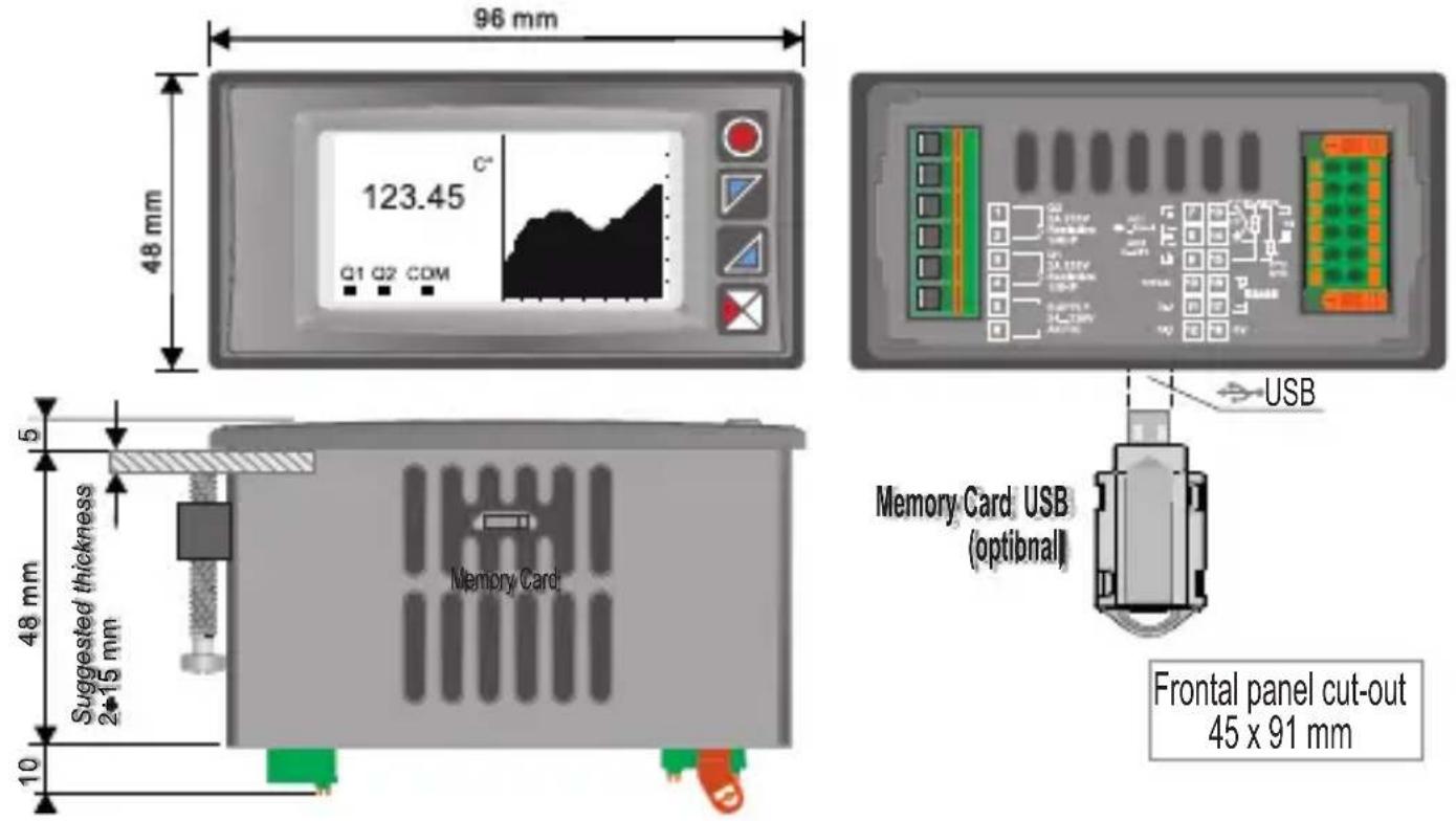
6 Electrical wirings

Although this controller has been designed to resist noises in an industrial environment, please notice the following safety guidelines:
- Separate control lines from the power wires.
- Avoid the proximity of remote control switches, electromagnetic meters, powerful engines.
- Avoid the proximity of power groups, especially those with phase control.
For permanently connected equipment:
- supply wiring must be ≥ 18 Awg with cables suitable for temperatures >70°C ;
- for requirements about any external switch or circuit-breaker see EN 61010-1 par. 6.11.3.1 and about external overcurrent protection devices see EN 61010-1 par. 9.6.2; the switch or circuit-breaker must be near the equipment.
6.1 Wiring diagram
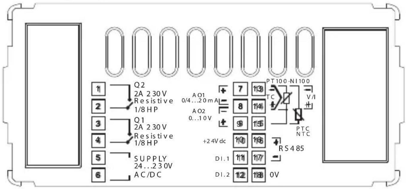
6.1.a Power supply
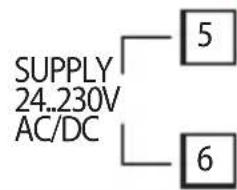
Switching supply with extended range 24...230 Vac/dc ±15% 50/60Hz – 8 VA (galvanic isolated)
6.1.b AN1 analogue imput

For thermocouples K, S, R, J, T, E, N, B.
- Comply with polarity.
- For possible extensions, use a compensated wire and terminals suitable for the thermocouples used (compensated).
- When shielded cable is used, it should be grounded at one side only.

For thermoresistances PT100, NI100.
- For the three-wire connection use wires with the same section.
- For the two-wire connection short-circuit terminals 14 and 15.
- When shielded cable is used, it should be grounded at one side only.


For thermoresistances NTC, PTC, PT500, PT1000 and linear potentiometers.
When shielded cable is used, it should be grounded at one side only to avoid ground loop currents.

For linear signals V / mA.
- Comply with polarity.
- When shielded cable is used, it should be grounded at one side only.
6.1.c Example of connection for linear input Volt and mA

For linear signals 0/4..20 mA with three-wire sensor.
Comply with polarity:
A= Sensor output (+)
B= Sensor ground (-)
C= Sensor power supply (+24 Vdc / 35mA)
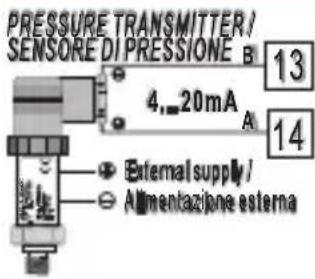
For linear signals 0/4..20 mA with external power of sensor.
Comply with polarity:
A= Sensor output (+)
B= Sensor ground (-)

For linear signals 0/4..20 mA with two-wire sensor.
Comply with polarity:
A= Sensor output
C= Sensor power supply (+24 Vdc / 35mA)
6.1.d Serial input

RS485 Modbus RTU communication
6.1.e Relay Q1 output
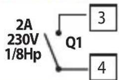
Capacity:
2 A / 250 V\~ for resistive loads.
NB: see picture below
6.1.f Relay Q2 output
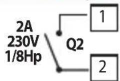
Capacity:
2A/250 V\~ for resistive loads.
NB: see picture below
![| Switching current [A] | Operations | | --------------------- | ---------- | | 0 | 10^7 | | 1 | ~10^6 | | 2 | ~10^5 | | 3 | ~10^4.5 | | 4 | ~10^4 | | 5 | ~10^3.5 | | 6 | ~10^3 | | 7 | ~10^2.5 | | 8 | ~10^2 |](/content/2026/05/904064/images/d0e314dcf77d4ec9ccede7c44e05b862014867f217f7b20bf6c62c5b256d40a9.jpg)
Electrical endurance Q1 / Q2.
2 A, 250 Vac, resistive load, 105 operations. 20/2 A, 250 Vac, = 0.3 , 105 operations.
6.1.g mA / Volt output
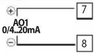
Pins 7-8: linear output in mA configurable using parameters as retransmission of process or alarm setpoints (see par. 112-116).

Pins 8-9: linear output in Volt configurable using parameters as retransmission of process or alarm setpoints (vedi par. 119-123).
6.1.h Digital Input 1

PNP digital input Digital input according to parameter 95 Short-circuit pins 10 and 11 to activate the digital input 1
7 Display and Key Functions
7.1 Keys

Keys are multifunction: in correspondence of each key its meaning is displayed. If no description is showed, press a key to visualize it. Some menus will be only displayed, when activated.
7.2 Display
It visualizes the process, the setpoints and all configuration parameters. The programming/ operation interface with text menus in 5 languages makes the navigation intuitive.

At first starting, display shows the language selection.

This page displays the process, the relays status and the serial communication (if available).

This page displays the process, the relays status and a graph representing the process trend.

This page displays the process and its graphic representation as bargraph.
8 Controller Functions
8.1 Memory Card (optional)
Parameters and setpoint values can be duplicated from one controller to another using the Memory card.
Insert memory card when the controller is off. On activation, after startup, the display visualizes "Load data" and "Esc" in correspondence of the relative keys (only if the correct values are saved in the memory card). Pressing "Load data" the controller loads the new values. Pressing "Esc" the device keeps the old values.

Updating Memory Card.
To update the memory card values, follow the procedure described on first mode, pressing "Esc" so as not to load the parameters on controller.
Enter configuration and change at least one parameter. Exit configuration. Changes are stored automatically.
8.2 Modifying alarm thresholds
Selecting one or more absolute/ band alarms, it is possible to modify the intervention thresholds directly by the user menu, without entering configuration.
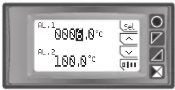
Press "Setpoint" to enter the thresholds modification.
For the modification procedure refer to the following table:
| Press Display Do | ||
| 1 “Sel” | Selects the setpoint to be modified. | Press e to modify the value. Pressing 010 it is possible to modify digit per digit. |
Press Display Do
| 2 | “Sel” | Selects the next setpoint (if active), otherwise go to point 3. | See point 1. |
| 3 | “Sel” | ^and √disappear Press “Esc” to exit procedure. | |
8.3 Latch on function
For the use with input Potentiometers max.6 kohm and Pot.max.150 kohm and with linear input (0..10 V, 0..60 mV, 0/4..20 mA), it is possible to associate the start value of the scale (par. 4 Lower limit V/I) to the minimum position of the sensor and the value of end scale (par. 5 Upper limit V/I) to the maximum position of the sensor.

To use the LATCH ON function: enter configuration, select Setting on par. 8 Latch on and press "Sel" (UA964802 shows the page in the picture).
For the calibration procedure refer to the following table:
| Press Display Do | |||
| 3 | ^ | Set the value to maximum. | To exit standard procedure press “Esc”.For zero settings place the sensor on the zero pointPlace the sensor on minimum operating value (associated with Lower limit V/I). |
| 1 | |||
| 2 | √ | Set the value on minimum. | Place the sensor on maximum operating value (associated with Upper limit V/I). |
| 4 | “0” | Set the virtual zero value. | Press “Esc” to exit procedure. |

8.4 Digital input functions
On the UA964802 model, digital inputs can be enabled by confi guring the par. 95 Digital input 1 and the par. 100 Digital Input 2.
- Run: allows the action of relays and linear output.
- Hold: locks the conversion.
• Tare zero (AI): selects to zero the process value (tare function). - Alarm reset: if one or more alarms are selected with manual reset and alarm conditions are no longer present, closing the digital input it is possible to restore the alarm output.
- Totalizer reset: if the totalizer function is active, using the digital input it is possible to reset the counter.
• Peaks reset: min. peak/max. peak/peak-to-peak values are reset. - Sum total: if the sum function is active, using the digital input it is possible to increase the "sum" counter as indicated by the process value.
- Sum reset: if the sum function is active, using the digital input it is possible to reset the "sum" counter.
- Config. lock: if the digital input is active it is not possible to enter configuration or to modify the setpoints.
Selecting Digital input 1 or Digital input 2 on the alarm parameters, the related relays will activate togheter with the digital input; functions selected on parameters 95 and 100 will continue to work.
To store value in eeprom, see parameter 11 Store.
8.5 Peak values

The UA964802 is provided with a page for the visualization of peak values: max. peak, min. peak and peak-to-peak of analogue input. Keeping pressed "Rst" it is possible to reset the visualized values.
8.6 Totalizer function
The totalizer function, which can be enable by par. 9 Totalizer, performs an instant measurement of the process and sums it on a time basis to the previously totalized value.

On the dedicated page it is possible to see the instant process value and the totalized value: keeping pressed "Rst" it is possible to reset this value.
Ex.: if a sensor 4..20mA with F.s. 9000m 3 /hour is connected, it is necessary to select Hour on par. 9 Totalizer. The device will increase the totalized value considering the m 3 flowing each second (2.5m 3 ).
To store value in eeprom, see parameter 11 Store.
8.7 Sum function
The sum function, which can be enabled by par. 10 Sum function, allows to increase a counter adding the process value on command. It is an application typical for weighing systems and allows to know the total weighed value.

Press "Sum Function" to enter the function page. Pressing "+" the Process value is added to the counter. It is possible to reset the total value keeping pressed "Rst" and to fix "tare zero" of the process pressing "Tar".
Functions tare, sum and reset can be managed also by digital input if enabled on par. 95 Digital Input 1 and par. 100 Digital Input 2.
To store value in eeprom, see parameter 11 Store.
8.8 Customizable linear input
Selecting 16 steps on par. 17 V/I custom and connecting a linear sensor it is possible to customize the linear input for a max. of 16 steps. On parameters xx-Input value it is necessary to enter the value of the input to which the value selected on the corresponding parameter xx-Custom value will be related.
Example: sensor 0-10V.
01-Input value => 0.000V 01-Custom value => 0mBar
02-Input value => 2.000V 02-Custom value => 100mBar
03-Input value => 5.000V 03-Custom value=>500mBar
04-Input value => 10.000V 04-Custom value => 1000mBar
At each value in volt (input) it is related a value in mBar (customized): if the sensor supplies 2V the device visualizes 100mBar, if it supplies 5V the device visualizes 500mBar. For intermediate tension values the value in mBar is calculated linearly between the entered values containing it: 1V = 50mBar, 3.5V=300mBar and 7V=700mBar.
8.9 Alarm Intervention Modes
8.9.a Absolute alarm (absolute selection)
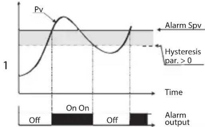
Absolute alarm and hysteresis value greater than "0" (Par. 58 hysteresis > 0).
N.B. The example refers to alarm 1; the function can also be enabled for alarms 2
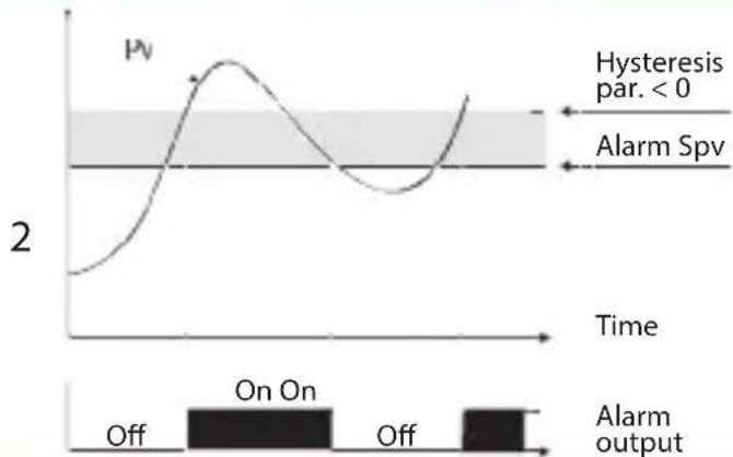
Absolute alarm and hysteresis value less than "0" (Par. 58 hysteresis < 0). N.B. The example refers to alarm 1; the function can also be enabled for alarms 2.
8.9.b Band alarm (band selection)

Band alarm and hysteresis value greater than "0" (Par. 58 hysteresis > 0).
N.B. The example refers to alarm 1; the function can also be enabled for alarms 2.

Band alarm and hysteresis value less than "0" (Par. 58 hysteresis < 0).
N.B. The example refers to alarm 1; the function can also be enabled for alarms 2.
8.9.c Digital input alarm (sel. "Digital input 1" or "Digital input 2")
Alarm related to digital input: the relay activates with digital input active.
8.9.d Loop Break Alarm (selection"L.B.A.")
Sensor alarm breakage: the relay activates in case of sensor breakage or sensor out of range.
8.9.e Remote control alarm (selection "remote Ctrl")
The relay activates writing 1 on word modbus 1015 for the alarm 1 and on word modbus 1016 for the alarm 2. Writing 0 the relay deactivates.
8.10 Data logger
UA964802 implements a basic Data logger function which can be enabled by par. 109 Data logger. Right after startup, the device starts storing the process data on EEPROM memory, the sampling time has to be selected on par. 108 Graphic time. Data can be read via Modbus starting from address 5001 (see next paragraph)
or via wireless reading the RFid memory directly from address 0x600 (1536). The first data give a reference about the type of saved process values: refer to the following table for the description of the saved data.
| 0x600 1536 Data logger: firmware version | ||
| 0x601 1537 Data logger: sensor type | ||
| 0x602 1538 Data logger: decimal point | ||
| 0x603 1539 Data logger: measure unit | ||
| 0x604 1540 Data logger: sampling time in seconds | ||
| 0x605 | 1541 | Data logger: end memory flag. 0 indicates that memory still available. 1 indicates that the memory is exhausted and the device resumed saving data from address 5017 |
| 0x610 1552 First saved value of analogue input | ||
| 0x611 1553 Second saved value of analogue input | ||
| ... ... ... | ||
| 0xFFFF 4095 Last saved value of analogue input | ||
The reading of value 0x8000 (-32768) indicates the end of the saved data: subsequent read data are not valid.
9 Serial communication
UA964802 equipped with RS485 can receive and broadcast data via serial communication using MODBUS RTU protocol. The device can be configured only as a Slave. This function enables the control of multiple controllers connected to a supervisory system. Each controller responds to a master query only if the query contains the same address as that in the parameter par. 126
Slave address.
The permitted addresses range from 1 to 254 and there must not be controllers with the same address on the same line.
Address 255 can be used by the master to communicate with all the connected equipment (broadcast mode), while with 0 all the devices receive the command, but no response is expected. UA964802 can introduce a delay (in milliseconds) in the response to the master request. This delay must be set on parameter 129 Serial Delay. Each parameter change is saved by the controller on EEPROM memory (100000 writing cycles).
NB: changes made to Words that are different from those reported in the following table can lead to malfunction.
| Modbus RTU protocol features | |
| Baud-rate | Selection on par. 127 Baud Rate:1.200 baud 28.800 baud2.400 baud 38.400 baud4.800 baud 57.600 baud9.600 baud 115.200 baud19.200 baud |
| Format | Selection on par. 128 Serial format:8, N, 1 (8 bit, no parity, 1 stop)8, E, 1 (8 bit, even parity, 1 stop)8, O, 1 (8 bit, odd parity, 1 stop)8, N, 2 (8 bit, no parity, 2 stop)8, E, 2(8 bit, even parity, 2 stop)8, O, 2 (8 bit, odd parity, 2 stop) |
| Supported functions | WORD READING (max 20 word) (0x03, 0x04) |
| SINGLE WORD WRITING (0x06) | |
| MULTIPLE WORDS WRITING (max 20 word) (0x10) | |
Looking at the table here below it is possible to find all available addresses and functions:
| RO | Read Only | R/W | Read / Write | WO | Write Only |
| Modbus Address | Description | Read Only | Reset value |
| 0 Device type RO EEPROM | |||
| 1 Software version RO EEPROM | |||
| 5 Slave address R/W EEPROM | |||
| 6 Boot version RO EEPROM | |||
| 1000 | Process (degrees.tenths for temperature sensors; digit for linear sensors) | RO 0 | |
| 1001 | Min. peak (degrees.tenths for temperature sensors; digit for linear sensors) | RO 0 | |
| 1002 | Max. peak (degrees.tenths for temperature sensors; digit for linear sensors) | RO 0 | |
| 1003 | Peak-to-peak (degrees.tenths for temperature sensors; digit for linear sensorsati) | RO 0 | |
| 1004 | Totalizer value (H) | RO | EEPROM |
| 1005 | Totalizer value (L) | RO | EEPROM |
| 1006 | Sum value (H) | RO | EEPROM |
| 1007 | Sum value (L) | RO | EEPROM |
| 1008 | Cold junction temperature (degrees.tenths) | RO | EEPROM |
| 1009 | Relays status (0 = Off, 1 = On):Bit 0 = Relay Q1Bit 1 = Relay Q2 | RO 0 | |
| 1010 | Digital inputs status (0 = Off, 1 = Active):Bit 0 = D.I.1Bit 1 = D.I.2 | RO - | |
| 1011 | Keys status (0 = released, 1 = pressed):Bit 0 = Bit 1 =Bit 2 =Bit 3 = Bit 1 =Bit 2 =Bit 3 = | RO 0 | |
| 1012 | Error flagsBit 0 = Cold junction errorBit 1 = Process error (sensor)Bit 2 = Eeprom writing errorBit 3 = Eeprom reading errorBit 4 = Missing calibration data errorBit 5 = Generic errorBit 6 = Hardware error | RO 0 | |
| 1013 | Alarms status (0 = None, 1 = Active)Bit 0 = Alarm 1Bit 1 = Alarm 2 | RO 0 | |
| 1014 | Manual reset: write 0 to reset all alarms.In reading (0 = Not resettable, 1 = Resettable)Bit 0 = Alarm 1Bit 1 = Alarm 2 | R/W 0 | |
| 1015 | Alarm 1 status (remote control) | R/W | 0 |
| 1016 | Alarm 2 status (remote control) | R/W | 0 |
| 1017 | mA analogue output value (remote control) | R/W | 0 |
| 1018 | Volt analogue output value (remote control) | R/W | 0 |
| 1019 | Run by serial0 = Inhibited outputs1 = Active outputs | R/W 1 | |
| 1020 | Hold by serial0 = Active analogue input1 = Analogue input in Hold | R/W 0 | |
| 1021 | Tare zero AI (write 1) R/W 0 | ||
| 1022 | Totalizer reset (write 1) R/W 0 | ||
| 1023 | Peaks reset (write 1) R/W 0 | ||
| 1024 | Sum total (write 1) R/W 0 | ||
| 1025 | Total sum reset (write 1) R/W 0 | ||
| 2001 | Parameter 1 R/W EEPROM | ||
| 2002 | Parameter 2 R/W EEPROM | ||
| 2150 | Parameter 150 R/W EEPROM | ||
| 4001 | Parameter 1* R/W EEPROM | ||
| 4002 | Parameter 2* | R/W | EEPROM |
| 4150 | Parameter 150* | R/W | EEPROM |
* Parameters modified using serial address 4001 to 4150, will be stored on eeprom only after 10s since last writing of one parameter.
10 Configuration
10.1 Modifying configuration parameters
For configuration parameters see par. 11
| Press Display Do | |||
| 1 | "Configuration" | Shows 0000 with the 1st digit selected. | |
| 2 | ^ and √ | Changes the selected digit and moves to the next one using | Enter password 1234 |
| 3 | "Sel" to confirm | Shows the names of the parameter groups. | |
| 4 | ^ and √ | Scroll up / down the parameter groups. | |
| 5 | "Sel" to enter the parameter group | Shows the parameters of the selected group. | Press ^ and √ to select parameter to be modified. |
| 6 | "Sel" to enter the parameter modification | Shows all parameter possible selections or the parameter numeric value. | Press ^ and √ to modify parameter. For numeric parameters, pressing it is possible to modify digit-to-digit. Press "Sel" to confirm modification. Press "<" to exit without modify. |
10.2 Loading default values
Enter password 9999 to restore factory settings of the device.
11 Table of configuration parameters
The following table includes all parameters. Some of them will not be visible on the models which are not provided with relevant Hardware data.
11.1 Analogue input
Parameters to configure the analogue input.
1 Sensor type
Analogue input configuration/sensor selection
Thermocouple K (Default) -260 °C..1360 °C
Thermocouple S -40 °C..1760 °C
Thermocouple R -40 °C..1760 °C
Thermocouple J -200 °C..1200 °C
Thermocouple T -260 °C..400 °C
Thermocouple E -260 °C..1000 °C
Thermocouple N -260 °C..1280 °C
Thermocouple B +80 °C..1820 °C
Pt100 -200 °C..600 °C
Ni100 -60 °C..180 °C
NTC 10kOhm -40 °C..125 °C
PTC 1kOhm -50 °C..150 °C
Pt500 -100 °C..600 °C
Pt1000 -100 °C..600 °C
0..10 V
0.20 mA
4..20 mA
0.60 mV
Pot. max. 6 kOhm
Pot. max. 150 kOhm
2 Decimal Point
| Selects type of the visualized decimal point |
| 0 No decimals. Default |
| 0.0 1 Decimal |
| 0.00 2 Decimals |
| 0.000 3 Decimals |
3 Measure unit
| Selects the visualized measure unit | ||
| °C (Default) | kg | N |
| °F | q | kN |
| K | t | % |
| V | oz | L |
| mV | lb | gal |
| A | m/s | mmHg |
| mA | m/m | atm |
| Bar | m/h | mH2O |
| mBar | l/s | Nm |
| psi | l/m | kNm |
| Pa | l/h | kgf |
| mm | m3/s | kgp |
| cm | m3/m | kip |
| dm | m3/h | lbf |
| m | rpm | ozf |
| km | %rh | pcs |
| in | ph | |
| g | ||
4 Lower limit V/I
Range AN1 lower limit only for linear input. Ex: with input 4..20 mA this parameter takes value associated to 4 mA -32767 + 32767 [digit 1 ], Default: 0.
5 Upper limit V/I
Range AN1 upper limit only for linear input. Ex: with input 4..20 mA this parameter takes value associated to 20 mA -32767 + 32767 [digit 1 ], Default: 1000.
6 Offset calibration
Value added / subtracted to the process visualization (usually correcting the value of environmental temperature) -1000..+1000 [digi] for linear sensors and potentiometers. -100.0..+100.0 (degrees.tenths for temperature sensors). Default 0.0.
7 Gain calibration
Percentage value that is multiplied for the process value (allows to calibrated the working point) -100.0%..+100.0%, Default: 0.0 ex: to correct the range from 0..1000°C showing 0..1010°C, set the par. to -1.0.
8 Latch On
Automatic setting of limits for linear inputs and potentiometers. (see par. 8.3) Disabled (Default) Enabled Setting
9 Totalizer
Visualizes the total fluid volume considering the sensor signal as unit/time value (ex. if the connected sensor has an output 4..20mA with F.s. 2000m 3 /hour, the parameter 9 Totalizer has to be selected as Hour and the display will visualize the total fluid volume from the last RESET/START signal). (see par. 8.6) Disabled Display visualizes the process (Default) Second Display visualizes the flow in unit/s Minute Display visualizes the flow in unit/min Hour Display visualizes the flow in unit/hour
10 Sum function
Enables the sum function and its dedicated page. Allows to sum the process value to a variable. (see par. 8.7)
Disabled (Default)
Enabled
11 Store
Enables to store in eeprom the values of peak, totalizer, sum function and tare zero. If disabled, at starting the above-mentioned values start from 0.
The storing is done automatically every 5 minutes.
Disabled (Default)
Enabled
12 Filter samples
ADC Filter: number of input sensor readings to calculate the mean that defines process value. NB: when readings increase, control loop speed slows down.
1..15 means Default: 10.
13 Sampling frequency
Sampling frequency of analogue / digital converter.
NB: Increasing the conversion speed will slow down reading stability (ex: for fast transients, as pressure, it is advisable to increase sampling frequency)
242 Hz 4.2ms (Maximum speed conversion)
123 Hz 8.2ms
62 Hz 16.1ms
50 Hz 20ms
39 Hz 25.6ms
33.2 Hz 30.1ms
19.6 Hz 51ms
16.7 Hz (Default) 59.9ms Ideal for filtering noises 50 / 60 Hz
12.5 Hz 80ms
10 Hz 100ms
8.33 Hz 120ms
6.25 Hz 160ms
4.17 Hz 240ms (Minimum speed conversion)
11.2 V/I custom
Parameters to configure the customizable linear input. (see par. 8.8)
17 V/I custom
Selects the linearization type for the analogue input if selected as linear.
Lower and upper limits. The input will be linearized by parameters 4 and 5 (Default)
16 spezzate. The input will be linearized by parameter 18-49
18 01-Input value
Defines the input value to which the 1st customized value is assigned 0..20000 Default: 0.
19 01-Custom value
Defines the 1st customized value assigned to the input -32767..32767 [Digit 1 ] Default: 0.
20 02-Input value
Defines the input value to which the 2nd customized value is assigned 0..20000 Default: 2000.
21 02-Custom value
Defines the 2nd customized value assigned to the input -32767..32767 [Digit 1 ] Default: 1000.
22 03-Input value
Defines the input value to which the 3rd customized value is assigned 0..20000 Default: 0.
23 03-Custom value
Defines the 3rd customized value assigned to the input -32767..32767 [Digit 1 ] Default: 0.
24 04-Input value
Defines the input value to which the 4th customized value is assigned 0..20000 Default: 0.
25 04-Custom value
Defines the 4th customized value assigned to the input -32767..32767 [Digit 1 ] Default: 0.
26 05-Input value
Defines the input value to which the 5th customized value is assigned 0..20000 Default: 0.
27 05-Custom value
Defines the 5th customized value assigned to the input -32767..32767 [Digit 1 ] Default: 0.
28 06-Input value
Defines the input value to which the 6th customized value is assigned 0..20000 Default: 0.
29 06-Custom value
Defines the 6th customized value assigned to the input -32767..32767 [Digit 1 ] Default: 0.
30 07-Input value
Defines the input value to which the 7th customized value is assigned 0..20000 Default: 0.
31 07-Custom value
Defines the 7th customized value assigned to the input -32767..32767 [Digit 1 ] Default: 0.
32 08-Input value
Defines the input value to which the 8th customized value is assigned 0..20000 Default: 0.
33 08-Custom value
Defines the 8th customized value assigned to the input -32767..32767 [Digit 1 ] Default: 0.
34 09-Input value
Defines the input value to which the 9th customized value is assigned 0..20000 Default: 0.
35 09-Custom value
Defines the 9th customized value assigned to the input -32767..32767 [Digit 1 ] Default: 0.
36 10-Input value
Defines the input value to which the 10th customized value is assigned 0..20000 Default: 0.
37 10-Custom value
Defines the 10th customized value assigned to the input -32767..32767 [Digit 1 ] Default: 0.
38 11-Input value
Defines the input value to which the 11th customized value is assigned 0..20000 Default: 0.
39 11-Custom value
Defines the 11th customized value assigned to the input -32767..32767 [Digit 1 ] Default: 0.
40 12-Input value
Defines the input value to which the 12th customized value is assigned 0..20000 Default: 0.
41 12-Custom value
Defines the 12th customized value assigned to the input -32767..32767 [Digit 1 ] Default: 0.
42 13-Input value
Defines the input value to which the 13th customized value is assigned 0..20000 Default: 0.
43 13-Custom value
Defines the 13th customized value assigned to the input -32767..32767 [Digit 1 ] Default: 0.
44 14-Input value
Defines the input value to which the 14th customized value is assigned 0..20000 Default: 0.
45 14-Custom value
Defines the 14th customized value assigned to the input -32767..32767 [Digit 1 ] Default: 0.
46 15-Input value
Defines the input value to which the 15th customized value is assigned 0..20000 Default: 0.
47 15-Custom value
Defines the 15th customized value assigned to the input -32767..32767 [Digit 1 ] Default: 0.
48 16-Input value
Defines the input value to which the 16th customized value is assigned 0..20000 Default: 0.
49 16-Custom value
Defines the 16th customized value assigned to the input -32767..32767 [Digit 1 ] Default: 0.
11.3 Alarm 1
Parameters to configure the Alarm 1. (see par. 8.9)
54 Alarm type
Alarm 1 selection Disabled (Default) Absolute alarm Band alarm Digital input 1 Digital input 2 Sensor failure Remote control by Modbus
55 Contact type
Selects the alarm 1 output contact and intervention type Normally open (Default) Normally closed N.O.-Disabled Power on N.C.-Disabled Power on
56 Alarm threshold
Selects the alarm 1 setpoint
-32767..+32767 [Digit 1 ] (degrees.tenths for temperature sensors), Default: 0.0.
57 Deviation threshold
Selects the deviation from alarm 1 setpoint for the band alarm
0..+32767 [Digit 1] (degrees.tenths for temperature sensors), Default: 0.0.
58 Hysteresis
Alarm 1 hysteresis
-1000..+1000 [Digit] (degrees.tenths for temperature sensors), Default: 0.0.
59 Reset type
Alarm 1 contact reset type
Automatic: (Default)
Manual: Manual reset by keyboard
Manual stored: Keeps relay status also after an eventual power failure
60 Error contact
State of contact for alarm 1 output in case of error
Open (Default)
Closed
62 Actuation delay
Alarm 1 delay.
-3600..+3600 seconds. Default: 0
Negative: delay in alarm output phase.
Positive: delay in alarm entry phase.
63 Lower limit
Lower limit for alarm 1 setpoint.
-32767..+32767 [Digit 1 ] (degrees.tenths for temperature sensors). Default: 0.
64 Upper limit
Upper limit for alarm 1 setpoint
-32767..+32767 [Digit 1 ] (degrees.tenths for temperature sensors). Default: 1000.
65 Protection
Alarm 1 set protection. Does not allow user to modify setpoint
Free Modification allowed (Default)
Lock Protected
Hide Protected and not visualized
11.4 Alarm 2
Parameters to configure the Alarm 2
69 Alarm type
Alarm 2 selection
Disabled (Default)
Absolute alarm
Band alarm
Digital input 1
Digital input 2
Sensor failure
Remote control by Modbus
70 Contact type
Selects the alarm 2 output contact and intervention type
Normally open (Default)
Normally closed
N.O.-Disabled Power on
N.C.-Disabled Power on
71 Alarm threshold
Selects the alarm 2 setpoint
-32767..+32767 [Digit 1 ] (degrees.tenths for temperature sensors), Default: 0.0.
72 Deviation threshold
Selects the deviation from alarm 2 setpoint for the band alarm 0..+32767 [Digit 1 ] (degrees.tenths for temperature sensors), Default: 0.0.
73 Hysteresis
Alarm 2 hysteresis -1000..+1000 [Digit] (degrees.tenths for temperature sensors), Default: 0.0.
74 Reset type
Alarm 2 contact reset type Automatic: (Default) Manual: Manual reset by keyboard Manual stored: Keeps relay status also after an eventual power failure
75 Error contact
State of contact for alarm 2 output in case of error Open (Default) Closed
77 Actuation delay
Alarm 2 delay. -3600..+3600 seconds. Default: 0 Negative: delay in alarm output phase. Positive: delay in alarm entry phase.
78 Lower limit
Lower limit for alarm 2 setpoint. -32767..+32767 [Digit 1 ] (degrees.tenths for temperature sensors). Default: 0.
79 Upper limit
Upper limit for alarm 2 setpoint -32767..+32767 [Digit 1 ] (degrees.tenths for temperature sensors). Default: 1000.
80 Protection
Alarm 2 set protection. Does not allow user to modify setpoint Free Modification allowed (Default) Lock Protected Hide Protected and not visualized
11.5 Display
84 Language
Selects the language
English (Default)
Italiano
Deutsch
Français
Español
86 Contrast
Selects the contrast value for the display
0%..100%, Default: 80%.
87 Reverse
Enables the display reverse visualization
Disabled (Default)
Enabled
88 Screen timeout
Determines the time after which the display switches to standby mode when no key has been pressed, reducing brightness so as not to be an inconvenience in environments with little lighting and to extend the display's life time.
Always on (Default)
15 seconds
2 minutes
30 minutes
30 seconds
5 minutes
1 hour
1 minute
10 minutes
89 Display direction
Selects the display visualization direction. Horizontal (Default) Vertical
90 Starting page
Selects the page visualized at starting after the initial splash screen Process (Default) Graphic Peak values Totalizer Sum function
11.6 Digital input 1
Parameters to configure the digital input 1.
95 Digital input function
Selects the digital input 1 function. (see par. 8.4) Disabled (Default) Run Hold Tare zero (AI) (impulse functioning) Alarm reset Totalizer reset (impulse functioning) Peaks reset Sum total (impulse functioning) Sum reset (impulse functioning) Config. lock
96 Contact type
Selects the digital input 1 inactive contact. Normally open (Default) Executes function with closed contact Normally closed Executes function with open contact
11.7 Digital input 2
Parameters to configure the digital input 2. (see par. 8.4)
100 Input function
Selects the digital input 2 function
Disabled (Default)
Run
Hold
Tare zero (AI) (impulse functioning)
Alarm reset
Totalizer reset (impulse functioning)
Peaks reset
Sum total (impulse functioning)
Sum reset (impulse functioning)
Config. lock
101 Contact type
Selects the digital input 2 inactive contact.
Normally open (Default) Executes function with closed contact
Normally closed Executes function with open contact
11.8 Graphic
Parameters to configure the trend and bar graph management.
105 Graphic type
Selects the type of graph to be visualized on the relevant page.
Trend (Default)
Bar graph
106 Lower limit
Trend or bar graph lower limit.
-32767 + 32767 [Digit 1 ], Default: 0.
107 Upper limit
Trend or bar graph upper limit.
-32767 + 32767 [Digit 1 ], Default: 1000.
108 Trend time
Selects the trend sampling time.
1..3600 seconds, Default: 60s.
109 Data logger
Enables the over time registration of the process in eeprom
The sampling time is equal to the trend upgrading time. (see par. 8.10)
Disabled (Default)
Enabled
110 Data logger time
Selects the data logger sampling time.
1..3600 seconds, Default: 60s.
11.9 Analogue output in mA
Parameters to configure the analogue output in mA
112 Retransmission
Enables analogue output
Disabled (Default)
Process
Alarm 1
Alarm 2
Remote control by Modbus
113 Signal type
Selects the signal for the analogue output in mA
0.20 mA
4..20 mA (Default)
114 Lower limit
Analogue output mA lower limit range
-32767..+32767 [Digit 1 ] (degrees.tenths for temperature sensors), Default: 0
115 Upper limit
Analogue output mA upper limit range
-32767..+32767 [Digit 1] (degrees.tenths for temperature sensors) Default: 1000
116 Error value
Selects the value of the analogue output in mA in case of error
0 mA (Default)
4 mA
20 mA
11.10 Analogue output in Volt
Parameters to configure the analogue output in Volt
119 Retransmission
Enables analogue output
Disabled (Default)
Process
Alarm 1
Alarm 2
Remote control by Modbus
120 Signal type
Selects the signal for the analogue output in Volt
0..10 V (Default)
121 Lower limit
Analogue output Volt lower limit range
-32767..+32767 [Digit 1 ] (degrees.tenths for temperature sensors), Default: 0
122 Upper limit
Analogue output Volt upper limit range
-32767..+32767 [Digit 1] (degrees.tenths for temperature sensors) Default: 1000
123 Error value
Selects the value of the analogue output in Volt in case of error 0 V (Default) 10 V
11.11 Comunication port
Parameters to configure the serial communication port. (see par. 9)
126 Slave address
Selects the slave address for serial communication 1..254. Default: 240
127 Baud rate
Selects the baud rate for serial communication 1.200 baud 2.400 baud 4.800 baud 9.600 baud 19.200 baud (Default) 28.800 baud 39.400 baud 57.600 baud 115.200 baud
128 ComPort setting
Selects the format for the serial communication
8,N,1 8bit, No parity, 1 Stop bit (Default)
8,E,1 8bit, Even parity, 1 Stop bit
8,0,1 8bit, Odd parity, 1 Stop bit
8,N,2 8bit, No parity, 2 Stop bit
8,E,2 8bit, Even parity, 2 Stop bit
8,0,2 8bit, Odd parity, 2 Stop bit
129 Serial delay
Selects the serial delay
0..100 milliseconds. Default: 10
Notes / Updates
Table of configuration parameters
1 Sensor type 29
2 Decimal Point 30
3 Measure unit 30
4 Lower limit V/I 30
5 Upper limit V/I 31
6 Offset calibration 31
7 Gain calibration 31
8 Latch On 31
9 Totalizer 31
10 Sum function 32
11 Store 32
12 Filter samples 32
13 Sampling frequency 32
17 V/I custom 33
18 01-Input value 33
19 01-Custom value 33
20 02-Input value 33
21 02-Custom value 33
22 03-Input value 33
23 03-Custom value 34
24 04-Input value 34
25 04-Custom value 34
26 05-Input value 34
27 05-Custom value 34
28 06-Input value 34
29 06-Custom value 34
30 07-Input value 34
31 07-Custom value 35
32 08-Input value 35
33 08-Custom value 35
34 09-Input value 35
35 09-Custom value 35
36 10-Input value 35
37 10-Custom value 35
38 11-Input value 35
39 11-Custom value 36
40 12-Input value 36
41 12-Custom value 36
42 13-Input value 36
43 13-Custom value 36
44 14-Input value 36
45 14-Custom value 36
46 15-Input value 36
47 15-Custom value 37
48 16-Input value 37
49 16-Custom value 37
54 Alarm type 37
55 Contact type 37
56 Alarm threshold 38
57 Deviation threshold 38
58 Hysteresis 38
59 Reset type 38
60 Error contact 38
62 Actuation delay 38
63 Lower limit 38
64 Upper limit 39
65 Protection 39
69 Alarm type 39
70 Contact type 39
71 Alarm threshold 39
72 Deviation threshold 40
73 Hysteresis 40
74 Reset type 40
75 Error contact 40
77 Actuation delay 40
78 Lower limit 40
79 Upper limit 40
| 80 | Protection | 41 |
| 84 | Language | 41 |
| 86 | Contrast | 41 |
| 87 | Reverse | 41 |
| 88 | Screen timeout | 41 |
| 89 | Display direction | 42 |
| 90 | Starting page | 42 |
| 95 | Digital input function | 42 |
| 96 | Contact type | 42 |
| 100 | Input function | 43 |
| 101 | Contact type | 43 |
| 105 | Graphic type | 43 |
| 106 | Lower limit | 43 |
| 107 | Upper limit | 44 |
| 108 | Trend time | 44 |
| 109 | Data logger | 44 |
| 110 | Data logger time | 44 |
| 112 | Retransmission | 44 |
| 113 | Signal type | 44 |
| 114 | Lower limit | 45 |
| 115 | Upper limit | 45 |
| 116 | Error value | 45 |
| 119 | Retransmission | 45 |
| 120 | Signal type | 45 |
| 121 | Lower limit | 45 |
| 122 | Upper limit | 46 |
| 123 | Error value | 46 |
| 126 | Slave address | 46 |
| 127 | Baud rate | 46 |
| 128 | ComPort setting | 47 |
| 129 | Serial delay | 47 |

WACHENDORFF



- INTRODUCTION
- 1 SAFETY GUIDE LINES
- 2 MODEL IDENTIFICATION
- 3 TECHNICAL DATA
- 3.1 GENERAL DATA
- 5 DIMENSIONS AND INSTALLATION
- 6 ELECTRICAL WIRINGS
- FOR PERMANENTLY CONNECTED EQUIPMENT
- 6.1 WIRING DIAGRAM
- 6.1.A POWER SUPPLY
- 6.1.B AN1 ANALOGUE IMPUT
- FOR THERMORESISTANCES PT100, NI100
- FOR THERMORESISTANCES NTC, PTC, PT500, PT1000 AND LINEAR POTENTIOMETERS
- FOR LINEAR SIGNALS V / MA
- 6.1.C EXAMPLE OF CONNECTION FOR LINEAR INPUT VOLT AND MA
- 6.1.D SERIAL INPUT
- 6.1.E RELAY Q1 OUTPUT
- 6.1.F RELAY Q2 OUTPUT
- ELECTRICAL ENDURANCE Q1 / Q2
- 6.1.G MA / VOLT OUTPUT
- 6.1.H DIGITAL INPUT 1
- 7 DISPLAY AND KEY FUNCTIONS
- 7.1 KEYS
- 7.2 DISPLAY
- 8 CONTROLLER FUNCTIONS
- 8.1 MEMORY CARD (OPTIONAL)
- UPDATING MEMORY CARD
- 8.2 MODIFYING ALARM THRESHOLDS
- 8.3 LATCH ON FUNCTION
- 8.4 DIGITAL INPUT FUNCTIONS
- 8.5 PEAK VALUES
- 8.6 TOTALIZER FUNCTION
- 8.7 SUM FUNCTION
- 8.8 CUSTOMIZABLE LINEAR INPUT
- 8.9 ALARM INTERVENTION MODES
- 8.9.A ABSOLUTE ALARM (ABSOLUTE SELECTION)
- 8.9.B BAND ALARM (BAND SELECTION)
- 8.9.C DIGITAL INPUT ALARM (SEL. "DIGITAL INPUT 1" OR "DIGITAL INPUT 2")
- 8.9.D LOOP BREAK ALARM (SELECTION"L.B.A.")
- 8.9.E REMOTE CONTROL ALARM (SELECTION "REMOTE CTRL")
- 8.10 DATA LOGGER
- 9 SERIAL COMMUNICATION
- SLAVE ADDRESS
- 10 CONFIGURATION
- 10.1 MODIFYING CONFIGURATION PARAMETERS
- 10.2 LOADING DEFAULT VALUES
- 11 TABLE OF CONFIGURATION PARAMETERS
- 11.1 ANALOGUE INPUT
- 1 SENSOR TYPE
- 2 DECIMAL POINT
- 3 MEASURE UNIT
- 4 LOWER LIMIT V/I
- 5 UPPER LIMIT V/I
- 6 OFFSET CALIBRATION
- 7 GAIN CALIBRATION
- 8 LATCH ON
- 9 TOTALIZER
- 10 SUM FUNCTION
- 11 STORE
- 12 FILTER SAMPLES
- 13 SAMPLING FREQUENCY
- 11.2 V/I CUSTOM
- 17 V/I CUSTOM
- 18 01-INPUT VALUE
- 19 01-CUSTOM VALUE
- 20 02-INPUT VALUE
- 21 02-CUSTOM VALUE
- 22 03-INPUT VALUE
- 23 03-CUSTOM VALUE
- 24 04-INPUT VALUE
- 25 04-CUSTOM VALUE
- 26 05-INPUT VALUE
- 27 05-CUSTOM VALUE
- 28 06-INPUT VALUE
- 29 06-CUSTOM VALUE
- 30 07-INPUT VALUE
- 31 07-CUSTOM VALUE
- 32 08-INPUT VALUE
- 33 08-CUSTOM VALUE
- 34 09-INPUT VALUE
- 35 09-CUSTOM VALUE
- 36 10-INPUT VALUE
- 37 10-CUSTOM VALUE
- 38 11-INPUT VALUE
- 39 11-CUSTOM VALUE
- 40 12-INPUT VALUE
- 41 12-CUSTOM VALUE
- 42 13-INPUT VALUE
- 43 13-CUSTOM VALUE
- 44 14-INPUT VALUE
- 45 14-CUSTOM VALUE
- 46 15-INPUT VALUE
- 47 15-CUSTOM VALUE
- 48 16-INPUT VALUE
- 49 16-CUSTOM VALUE
- 11.3 ALARM 1
- 54 ALARM TYPE
- 55 CONTACT TYPE
- 56 ALARM THRESHOLD
- 57 DEVIATION THRESHOLD
- 58 HYSTERESIS
- 59 RESET TYPE
- 60 ERROR CONTACT
- 62 ACTUATION DELAY
- 63 LOWER LIMIT
- 64 UPPER LIMIT
- 65 PROTECTION
- 11.4 ALARM 2
- 69 ALARM TYPE
- 70 CONTACT TYPE
- 71 ALARM THRESHOLD
- 72 DEVIATION THRESHOLD
- 73 HYSTERESIS
- 74 RESET TYPE
- 75 ERROR CONTACT
- 77 ACTUATION DELAY
- 78 LOWER LIMIT
- 79 UPPER LIMIT
- 80 PROTECTION
- 11.5 DISPLAY
- 84 LANGUAGE
- 86 CONTRAST
- 87 REVERSE
- 88 SCREEN TIMEOUT
- 89 DISPLAY DIRECTION
- 90 STARTING PAGE
- 11.6 DIGITAL INPUT 1
- 95 DIGITAL INPUT FUNCTION
- 96 CONTACT TYPE
- 11.7 DIGITAL INPUT 2
- 100 INPUT FUNCTION
- 101 CONTACT TYPE
- 11.8 GRAPHIC
- 105 GRAPHIC TYPE
- 106 LOWER LIMIT
- 107 UPPER LIMIT
- 108 TREND TIME
- 109 DATA LOGGER
- 110 DATA LOGGER TIME
- 11.9 ANALOGUE OUTPUT IN MA
- 112 RETRANSMISSION
- 113 SIGNAL TYPE
- 114 LOWER LIMIT
- 115 UPPER LIMIT
- 116 ERROR VALUE
- 11.10 ANALOGUE OUTPUT IN VOLT
- 119 RETRANSMISSION
- 120 SIGNAL TYPE
- 121 LOWER LIMIT
- 122 UPPER LIMIT
- 123 ERROR VALUE
- 11.11 COMUNICATION PORT
- 126 SLAVE ADDRESS
- 127 BAUD RATE
- 128 COMPORT SETTING
- 129 SERIAL DELAY
- NOTES / UPDATES
- TABLE OF CONFIGURATION PARAMETERS
- WACHENDORFF
Brand : Wachendorff
Model : UA964802
Category : Measuring instrument