
MA964802 - Industrial digital display Wachendorff - Free user manual and instructions
Find the device manual for free MA964802 Wachendorff in PDF.


| Product Type | Digital Panel Meter |
| Model | MA964802 |
| Brand | Wachendorff |
| Dimensions (W x H x D) | 96 x 48 x 100 mm |
| Panel Cutout | 92 x 45 mm |
| Weight | Approx. 200 g |
| Power Supply | 24 V DC (10-30 V DC) |
| Power Consumption | < 5 W |
| Display Type | 6-digit LED, red, 14 mm height |
| Input Signal | Universal (voltage, current, RTD, thermocouple) |
| Measurement Range | Depends on input type |
| Accuracy | ±0.1% of reading + 1 digit |
| Sampling Rate | 10 readings per second |
| Operating Temperature | -10°C to +55°C |
| Protection Rating | IP65 (front panel) |
| Functions | Measurement, display, min/max, tare, scaling |
| Output Options | Analog output (0-10 V / 4-20 mA), alarm relay |
| Communication | RS485 Modbus RTU (optional) |
| Cleanliness | Wipe with dry cloth; no solvents |
| Safety | Double insulation; overvoltage category II |
| Spare Parts / Repairability | Replacement terminal blocks, firmware update via PC |
| Mounting | Panel mount with clamping frame |
| Compliance | CE, UL, RoHS |
| Manual Language | English (54 pages) |
Frequently Asked Questions - MA964802 Wachendorff
User questions about MA964802 Wachendorff
0 question about this device. Answer the ones you know or ask your own.
Ask a new question about this device
Download the instructions for your Industrial digital display in PDF format for free! Find your manual MA964802 - Wachendorff and take your electronic device back in hand. On this page are published all the documents necessary for the use of your device. MA964802 by Wachendorff.
USER MANUAL MA964802 Wachendorff
1 Safety standards....6
2 Identification of the model....6
3 Technical data....7
3.1 General features....7
4 Hardware features....7
4.1 Software features....8
5 Dimension and installation....9
6 Electrical connections.... 10
6.1 Connection diagram 10
7 Function of keys and of the display....13
7.1 Keys....13
7.2 Display....13
7.3 Display mode....14
8 Functions of the instrument.... 16
8.1 Displaying the variables.... 16
8.2 Editing values of the variables 16
8.3 Editing alarm thresholds....17
8.4 COM1 status.... 18
8.5 Acquisition of potentiometer limits....19
8.6 Digital input 1 and 2 functions....20
8.7 Digital input 3 functions....21
8.8 Alarm triggering modes....21
9 COM1 serial port in Multimaster mode 23
10 COM2 Serial Communication 23
10.1 Notes to access parameters....25
11 Error messages....31
12 Configuration....31
12.1 Editing configuration parameters 31
12.2 Loading default values 32
12.3 Configuration via memory card 32
12.4 Creation of the memory card 33
12.5 Loading configuration from memory card 33
13 Configuration parameters table 34
13.1 Display.... 34
13.2 COM1 serial port 35
13.3 Variable 1..8....37
13.4 Potentiometer input 46
13.5 Alarm 1..2....47
13.6 Digital input 1..2 49
13.7 Digital input 3....50
13.8 COM2 serial port 50
13.9 USB port....51
Introduction
Thank you for having chosen a Pixsys instrument. MA964802 is a remote Modbus display to view and modify variables on slave devices connected to an RS485 network. In a 96x48mm format, it is supplied with 128x64 pixel graphical OLED d isplay (monochrome yellow). Distinctive feature is the intuitive multi-language interface with detailed text menus. Connectivity is provided by a second RS485 serial port with Modbus RTU slave protocol and by a Virtual Comm Port on micro-USB.
1 Safety standards
Carefully read the instructions and safety measures in this manual before using the device. Disconnect power before performing any interventions on the electrical connections or hardware settings.
Only qualified personnel may use/perform maintenance in full respect of the technical data and declared environmental conditions.
Do not dispose of electrical appliances together with household waste.
In compliance with the European Directive 2002/96/EC, waste electrical equipment must be collected separately for eco-compatible reuse or recycling.
2 Identification of the model
Model 24..230 Vac/Vdc +/-15% 50/60 Hz - 8 VA
MA964802 2 Relays 2 A + 3 digital inputs + 2 RS485 + RFid
3 Technical data
3.1 General features
Display 2.42" monochrome (yellow) OLED graphical display
| Operating temperature | Operating temperature 0-40°C - Humidity 35..95 Rh% |
| Protection | IP54 (on front) with gasketIP20 (container and terminals) |
| Material | Container: polycarbonate V0Front panel: silicon rubber |
| Weight Approximately 165g | |
4 Hardware features
| Power supply | Extended range power supply24..230 Vac/Vdc ±15% 50/60 Hz | Consumption: 8 VA. |
| COM1 serial port | Galvanically isolated RS485 interface | Modbus masterSpeed 1200..115200 bps |
| COM2 serial port | RS485 interface | Modbus SlaveSpeed 1200..115200 bps |
| Micro-USB port USB device interface | For connection to PC and memory card management. | |
| Relays output 2 Relays | 2 A - 250 Vac contacts.Resistive load. | |
| Digital inputs 3 Inputs | Confir urable PNP/NPN (2)Configurable NO / NC | |
| Potentiometer input | 1 input to set values of the variables. | Minimum 1 KΩ(power supply 24 Vac/Vdc) |
| Display | 2.42" monochrome yellow OLED technology. | Lifespan 150,000 hours(duration is specified as reaching 50% of the initial brightness) |
| Front keys 4 front keys To browse and edit data. | ||
4.1 Software features
Multi-language menu English/Italian/German/French/Spanish
| Master COM1 serial port | Modbus Master / Multimaster RTU / ASCII protocol |
| Number of variables | Max 8 reading/writing variables on Modbus slave devices. |
| Viewing variables | Configurable display by means of 1-4 variable parameters per page.Automatic selection of the maximum display font size for enhanced data reading. |
| Confi uration of variables | The following can be set for each variable:• Description (max 16 characters)• Unit of measurement (max 5 characters)• Selectable number of decimals• Format (bit, 16 bit, 32 bit, 32 bit floating point)• Numerical or enumerative display (for values 0..4): each numerical value has a corresponding displayed text• Processing of read data• Address of data and device |
| Automatic page scrolling | Possibility of enabling timed automatic scrolling of the display pages of the variables. |
| Encoder management from panel | Possibility of connecting a rotary encoder on the panel to the digital inputs to facilitate browsing of the various pages and to edit the variables and alarm setpoints. (Code 5300.55.001) |
| Communication status diagnosis | Possibility of viewing the communication status for each of the enabled variables. |
| Potentiometer setting | Possibility of setting the value of a variable with a potentiometer. Possibility of enabling writing of a variable by selecting it with a potentiometer.The potentiometer limits are stored with an acquisition procedure. |
| Alarms management ON/OFF with hysteresis | |
| Alarm mode | Absolute/Threshold, Band with instantaneous/delayed/retentive action and by digital input/communication failure / activation from serial communication |
| Slave COM2 serial port | Modbus RTU slave protocol |
| USB port | Virtual Com Port with Modbus RTU slave protocol.Memory card connection for parameter confi uration |
5 Dimension and installation

6 Electrical connections
Although this controller has been designed to resist noises in an industrial environment, please notice the following safety guidelines:
- Separate control lines from the power wires.
- Avoid the proximity of remote control switches, electromagnetic meters, powerful engines.
- Avoid the proximity of power groups, especially those with phase control.
For permanently connected equipment:
- supply wiring must be ≥ 18 Awg with cables suitable for temperatures >70^ ;
- for requirements about any external switch or circuit-breaker see EN 61010-1 par. 6.11.3.1 and about external overcurrent protection devices see EN 61010-1 par. 9.6.2; the switch or circuit-breaker must be near the equipment.
6.1 Connection diagram

6.1.a Power supply

Extended range switching power supply 24..230 Vac/Vdc ±15% 50/60 Hz – 8 VA (with galvanic isolation).
6.1.b COM1 serial port (Modbus master)
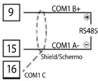
For connection to Modbus slave devices
- RS485 interface
• 1/4 line load (up to 128 nodes on bus)
• Common mode power supply +/-25V
• Protection from failure +/-60V - Modbus master or multimaster protocol
- RTU and Ascii mode.
6.1.c COM2 serial port (Modbus slave)

For connection to a Modbus master device
- RS485 interface
• 1/4 line load (up to 128 nodes on bus)
• Common mode power supply +/-25V - Protection from failure +/-60V
- Modbus slave RTU protocol
6.1.d Digital input DI.1

- PNP configuration, to activate input DI.1, short circuit terminals 11 (+24 Vdc) and 18 (DI.1).
(Activation Vi > 8.7V Deactivation Vi < 7.2V )
NPN configuration to activate input DI.1, short circuit terminals 10 (GND) and 18 (DI.1).
(Activation Vi < 7.2V Deactivation Vi < 8.7V )
Digital input DI.2

- PNP configuration, to activate input DI.2, short circuit terminals 11 (+24 Vdc) and 12 (DI.2).
(Activation Vi > 8.7V Deactivation Vi < 7.2V ) - NPN configuration, to activate input DI.2, short circuit terminals 10 (GND) and 12 (DI.2).
(Activation Vi < 7.2V Deactivation Vi < 8.7V )
6.1.e Digital input DI.3

To activate input DI.3, short circuit the terminals 11 (+24 Vdc) and 7 (DI.3). (Activation Vi > 12.1V Deactivation Vi < 12.0V )
6.1.f Potentiometer

For linear potentiometers.
- Use potentiometers with a resistive value greater than 1 K .
- When using a shielded cable, the shield must be connected to terminal 10 (GND).
6.1.g Q1 Relay Output
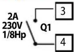
2 A / 250 Vac contacts capacity for resistive loads.
NB: see graph below
6.1.h Q2 Relay Output

flowchart
graph TD
    A["2A\n230V\n1/8Hp"] --> B["Q2"]
    B --> C["1"]
    B --> D["2"]
2 A / 250 Vac contacts capacity for resistive loads.
NB: see graph below

line
| Switching current [A] | Operations | | --------------------- | ---------- | | 0 | 10^1 | | 1 | ~10^0.5 | | 3 | ~10^0.2 | | 5 | ~10^0.1 | | 6 | ~10^0.05 | | 7 | ~10^0.02 | | 8 | ~10^0.01 |Electrical endurance Q1 / Q2.
2 A, 250 Vac, resistive load, 10^5 operations.
20/2 A, 250 Vac, cosφ = 0.3, 10⁵ operations.
6.1.i Encoder connection from panel
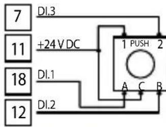
The drawing shows how to connect the encoder from the optional panel to browse and edit the values of the variables.
7 Function of keys and of the display 7.1 Keys

The keys are multifunction: the instrument shows the meaning of the various buttons on the display near the relative key. If there is no text near the key, press any button to display it. Some menus are only displayed if activated.
7.2 Display
Shows the values of the variables, the alarm setpoints, information regarding communication and all the configuration parameters. The multi-language interface makes navigation and access to the various functions intuitive.

Upon first start-up the display shows the language selection.
7.3 Display mode
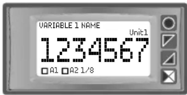
Shows the value of the first variable enabled with relative description, unit of measurement and the status of the alarm relays. The figure represents the display of "1 val. per page" setting in "Display -> View" parameter. The 1/8 text at the bottom indicates that the first of 8 pages used to represent enabled variables is being displayed.

Shows the value of the first two variables enabled with relative description, unit of measurement and status of the alarm relays.
The figure represents the display of "2 val. per page" setting in "Display -> View" parameter.

Shows the value of the first three variables enabled with relative description, unit of measurement and status of the alarm relays.
The figure represents the display of "3 val. per page" setting in "Display -> View" parameter.
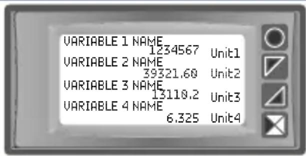
Shows the value of the first four variables enabled with relative description, unit of measurement and status of the alarm relays.
The figure represents the display of "4 val. per page" setting in "Display -> View" parameter.

Shows the value of the first three variables enabled, in expanded view mode. This mode, which can only be enabled when viewing 3 or 4 variables per page, displays the values of the variables with a larger character than that normally used for this representation, without viewing the description of the variables and only leaving the unit of measurement. This mode is enabled by setting the description of the relative variables as a sequence of spaces (zero description).

Shows the value of a variable by means of alphanumeric strings instead of the corresponding numerical value. This is possible for variable values between 0 and 4. A text string 8 characters long can be set for each of these values. For values lower than 0 and higher than 4, the variable is displayed in the traditional numerical format.

Represents the typical display of variables in offline mode. If the MA964802 display cannot establish the connection with the slave of the variable, and therefore cannot read/write the relative value, the numerical display is replaced by flashing question marks.
8 Functions of the instrument
8.1 Displaying the variables

If the set variables require more than one screen for their complete display, there are three ways to change the screen.
- Automatic mode. By setting the Scroll time parameter other than Disabled, if no keys are pressed, the screens will be displayed in cyclical timed mode with the interval set in the parameter. The display will then pass from one page to another automatically.
- Manual mode from keyboard. During standard display of the variables, pressing one of the buttons on the keyboard displays the navigation menu near the keys. You may scroll the display screens of the variables forward and backward using the 🔊 and ➕ keys. The currently viewed page number together with the total number of pages are displayed at the bottom of the screen.
- Manual mode with encoder from panel. By using the optional panel encoder accessory, connected to appropriately configured digital inputs, simply rotating the knob will allow you to scroll the display screens of the variables forwards or backwards.
8.2 Editing values of the variables
The navigation menus on the screens with variables which can be edited will also have the Sel key. If connected to the configured digital input 3, push the knob of the panel encoder instead of pressing the Sel and Ok keys. To edit a variable, see the procedure in the table below.
Press Effect Execute
| 1 |  | Selects the first variable to be edited. The value to be edited is highlighted.The navigation menu is replaced by the edit menu. | and to edit the value. Or, if available, use the knob of the panel encoder.The key allows you to edit one digit at a time. |
| 2 Ok |  | Confirms the edited value. If the page has another variable to be edited, it selects it. If there are no more variables to be edited, see point 3. | See point 1. |
| 3 Ok |  | and of the edit menu disappear and the navigation menu re-appears. | For further editing, see point 1. |
You exit the edit menu 5 seconds after the last key has been pressed. In this case, the modified data is saved.
8.3 Editing alarm thresholds
Setting one or more absolute or band alarms allows you to edit the triggering thresholds directly from the user menu without entering configuration.

Pressing Alarm thresholds grants access to the thresholds edit page.
See the procedure in the table below.
If connected to the configured digital input 3, push the knob of the panel encoder instead of pressing the Sel and Ok keys.
| Press Effect Execute | |||
| 1 | Sel | Selects the setpoint to edit | and to edit the value. Or, if available, use the knob of the panel encoder.The key allows you to edit one digit at a time. |
| 2 Ok | If active, the subsequent setpoint is selected.Otherwise go to point 3. | See point 1. | |
| 3 Ok | and disappear | Esc to exit the setpoint edit page. | |
8.4 COM1 status
This function, accessed by pressing Status CO on the main menu, allows you to monitor the communication status of each of the enabled variables.
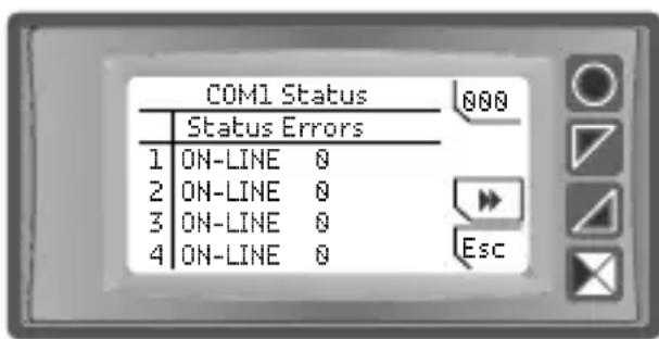
It indicates the current status of the variable (ON-LINE, OFF-LINE) and the number of communication errors or timeouts since the instrument was switched on. Pressing 000 allows you to reset the error counters, while pressing ▶ and ▶ displays the data of the variables not currently viewed on the page.
8.5 Acquisition of potentiometer limits
This function allows you to activate an "on field" calibration procedure of the minimum and maximum limits for the potentiometer input.
This function is enabled for configuration in the "Potentiom. input" section at the item "Acquisition". Once acquisition has been enabled and you have exited configuration, the following screen appears automatically.

At this point, proceed as follows:
- Set the potentiometer at the position you wish to associate to the value. Minimum
- Press ☑ to acquire the position and to store the value. The Acquired value will indicate the Min. value showing that the command has been executed.
- Set the potentiometer at the position you wish to associate to the value. Maximum
- Press ☑ to acquire the position and to store the value. The Acquired value will indicate the Max. value showing that the command has been executed.
At this point, the potentiometer acquisition procedure is finished; check that the potentiometer position and the Acquired value correspond.
Press Esc to exit the procedure.
8.6 Digital input 1 and 2 functions
The Modbus remote display MA964802 integrates some functions relative to the digital inputs: they can be enabled by configuring the Digital input 1 -> Input function parameter and the Digital input 2 -> Input function parameter.
- Enable outputs activates alarm relays.
- Reset alarms: if one or more alarms are set with manual reset and the alarm conditions are no longer present, closing the digital input allows you to restore the alarm output.
- Config. Block you may not access configuration with the digital input enabled.
- Incr. variab. x: with the digital input enabled, the corresponding variable is increased. The autorepeat function is enabled.
- Decr. variab. x: with the digital input enabled, the corresponding variable is decreased. The autorepeat function is enabled.
- Incr. var. sel. : with the digital input enabled, the variable currently selected is increased. The autorepeat function is enabled.
- Decr. var. sel.: with the digital input enabled, the variable currently selected is decreased. The autorepeat function is enabled.
- Encoder modif.: the digital input is enabled (coupled to the other digital input) to manage the panel encoder to modify variables and alarm setpoints.
By setting Digital input 1 or Digital input 2 in the Alarm x -> Alarm type parameters, the relative relays activate simultaneously with the digital input. The functions set in the Digital input 1 -> Input function and Digital input 2 -> Input function parameters continue to work.
By setting Digital input 1 or Digital input 2 in the Variable x -> Data source parameters, the corresponding variable will take on the value 0 or 1 depending on the status of the digital input. The functions set in the Digital input 1 -> Input function and Digital input 2 -> Input function parameters continue to work.
8.7 Digital input 3 functions
The Modbus remote display MA964802 integrates a further digital input associated to the function selected by the Digital input 3 -> Input function parameter variab.: the digital input allows you to enable or confirm editing of the variables on the currently displayed screen. This function is useful when using the panel encoder to edit values by means of digital inputs 1 and 2. In this case, pushing the encoder connects this input.
By setting Digital input 3 in the Alarm x -> Alarm type parameters, the relative relays activate simultaneously with the digital input. The function set in the Digital input 3 -> Input function parameter continues to work.
By setting Digital input 3 in the Variable x -> Data source parameters, the corresponding variable will take on the value 0 or 1 depending on the status of the digital input. The function set in the Digital input 3 -> Input function parameter continues to work.
8.8 Alarm triggering modes
MA964802 implements various alarm modes, described below.
8.8.a Absolute alarm ("Absolute" selection)

line
| Time Segment | Label | | ------------------ | ---------------------- | | On On | O⁻ | | Hysteresis par. > 0 | | | Alarm Spv | | | Alarm output | |Absolute alarm and hysteresis value greater than "0" (Par.58 Hysteresis>0).
N.B. The example refers to alarm 1; the function can also be enabled for alarm 2.
line
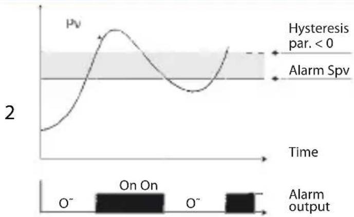
| Time | PV | |------|----| | 0 | Low | | Peak | High | | Low | Low | | Peak | High | | Low | Low | | Hysteresis par. < 0 | High | | Alarm Spv | High |Absolute alarm and hysteresis value less than "0" (Par.58 Hysteresis < 0). N.B. The example refers to alarm 1; the function can also be enabled for alarm 2.
8.8.b Band Alarm (Band selection)
line
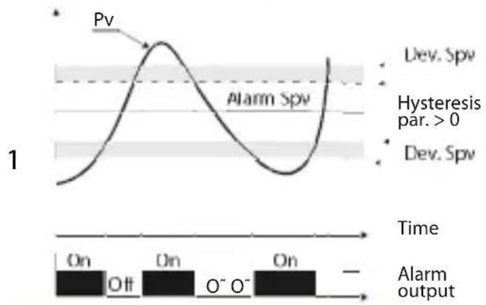
| Time | Label | |------|--------------| | On | On | | Off | Off | | On | On | | O⁻ | O⁻ | | O⁻ | O⁻ | | Dev | Dev. Spv | | Hysteresis par. > 0 | | | Dev | Dev. Spv | | Alarm Output | |Hysteresis band alarm value greater than "0" (Par.58 Hysteresis > 0).
N.B. The example refers to alarm 1; the function can also be enabled for alarm 2.

line
| Time | Pv | |------|----| | On On On | 0 | | Off | 10 | | Peak | ~2.5 | | Dev. Spv | 0 | | Hysteresis par. < 0 | < 0 | | Hysteresis par. < 0 | < 0 | | Alarm Spv | 0 | | Alarm output | Off |Hysteresis band alarm value less than "0" (Par.58 Hysteresis < 0).
N.B. The example refers to alarm 1; the function can also be enabled for alarm 2.
8.8.c Digital input alarm ("Digital input 1..3" selection)
Alarm relating to digital input: the relay is activated with the digital input enabled.
8.8.d Communication alarm ("Serial error") selection
Alarm related to an error (offline) of the COM1 serial port. The relay is activated when at least one variable exchanged on COM1 is OFF-LINE.
8.8.e Remote control alarm ("Remote ctrl" selection)
The relay is activated by writing 1 on Modbus 906 word for alarm 1 and Modbus 907 word for alarm 2. Writing 0 deactivates the relay.
9 COM1 serial port in Multimaster mode
The MA964802 device, aside from implementing standard Modbus master protocol, also implements a variant called Multimaster. This mode makes it possible to connect, aside from the various Modbus slave devices, up to 16 Pixsys Modbus multimaster devices on the RS485 serial network. This means that it will be possible to implement reading and writing of slave data from several MA964802 devices located at various points of the system.
A maximum of 16 MA964802 devices can be connected on the same network in multimaster mode. The slave devices connected to a network with devices in multimaster mode can have addresses from 1 to 238.
To configure the network of the multimaster system and to make it as efficient as possible, it is recommended to number the MA964802 devices starting from the address 254 (for the first multimaster device) and to descend to the address 239 (for the 16th and last multimaster device).
10 COM2 Serial Communication
MA964802 has the COM2 serial port (RS485) on which the Modbus R slave protocol is active. This makes it possible to connect the device to a supervision system or, more in general, to a Modbus RTU master device. Each instrument will respond to an interrogation by the Master only if it has the same address as that in the parameterCOM2 serial port -> Slave address. The addresses allowed go from 1 to 254 and there must not be devices with the same address on the same line. The address 255 can be used by the master to communicate with any
appliance connected, regardless of its address, while with the address 0 all the devices receive the command, but no response is expected (broadcast mode). MA964802 can introduce a delay (in milliseconds) before the response to the master's request. This delay must be set in the parameter COM2 serial port -> Response delay.
For the complete list of COM2 serial port parameters, see section "COM2 serial port" in the chapter "Configuration parameters table".
NB: By means of the COM2 serial port it is also possible to edit the instrument's configuration parameters; therefore pay attention that e very time parameters are changed, the instrument saves the values in the EEPROM memory (100000 writing cycles). This means that continuous texts with parameter values which always change, after exceeding the allowed number of writing cycles, can damage the EEPROM memory.
NB: changes to words other than those provided in the following table can cause the instrument to malfunction.
| Modbus RTU slave protocol features | |
| Baud-rate | Selectable from par. COM2 serial port-> Baud rate :1,200 baud 9,600 baud 38,400 baud2,400 baud 19,200 baud 57,600 baud4,800 baud 28,800 baud 115,200 baud |
| Format | Selectable from par. COM2 serial port-> Serial format:8, N, 1 (8 bits, no parity, 1 stop bit)8, E, 1 (8 bits, even parity, 1 stop bit)8, O, 1 (8 bits, odd parity, 1 stop bit)8, N, 2 (8 bits, no parity, 2 stop bits)8, E, 2 (8 bits, even parity, 2 stop bits)8, O, 2 (8 bits, odd parity, 2 stop bits) |
| Functions supported | WORD READING (max 20 word) (0x03, 0x04)SINGLE WORD WRITING (0x06)MULTIPLE WORDS WRITING (max 20 words) (0x10) |
The following is a list of all the addresses available and the functions supported:
| RO | Read Only | R/W | Read / Write | WO | Write Only |
10.1 Notes to access parameters
Access: Datas accessible through Modbus protocol that refer to 32 bit parameters or datas (2 words), must be 32 bit datas modified by the writing of two consecutive Modbus addresses (first the lowest and than the highest address). It is not enough to write only a word, even if the other one should remain unchanged.
The alphanumeric strings are stored into the relevant parameters, using the ascii codes of the used characters.
Each parameter (32 bit) contains 4 characters (each character 8 bit), to store strings with more than 4 characters, more consecutive parameters are used depending on the number of used characters, according to the following scheme:
Stored string "ABCDEFGHIJKLMNOP"
| Parameter Number Parameter Value String |
| Parameter n 0x44434241 ABCD |
| Parameter n+1 0x48474645 EFGH |
| Parameter n+2 0x4C4B4A49 IJKL |
| Parameter n+3 0x504F4E4D MNOP |
0x41 ascii code "A"
0x42 ascii code "B"
...
0x4F ascii code "O"
0x50 ascii code "P"
| Modbus Address | Description | Read Write | Reset value |
| 0 Device type RO EEPROM | |||
| 1 Software version RO EEPROM | |||
| 5 Address slave R/W EEPROM | |||
| 500 | Reload default dataThe following values (commands) are accepted:9999 Reload all the fault parameters9998 Reload all default parameters, leaving the baud rate, COM2 serial communication format and the device address (slave address) unchanged9997 Reload all default parameters, leaving the baud rate and COM2 serial port format unchanged9996 Reload all default parameters, leaving the device address (slave address) unchangedOnce the command received has been executed, the device restarts so that it is correctly initialised . | R/W 0 | |
| 900 | Alarm relay status (0 = Off, 1 = On):Bit 0 = Relay Q1Bit 1 = Relay Q2 | RO 0 | |
| 901 | Digital inputs status (0 = Off, 1 = On):Bit 0 = DI.1 Bit 1 = DI.2 Bit 2 = DI.3 | RO - | |
| 902 | Key status (0 = released, 1 = pressed):Bit 0 = Bit 1 = Bit 2 =Bit 3 = Bit 1 = Bit 2 =Bit 3 = | RO 0 | |
| 903 | Error flagsBit 0 = Incorrect calibration dataBit 1 = Incorrect parametersBit 2 = Incorrect status dataBit 3 = EEPROM memory writing errorBit 4 = EEPROM memory reading error | RO 0 | |
| 904 | Alarm status (0 = Absent, 1 = Present)Bit 0 = Alarm 1 Bit 1 = Alarm 2 | RO 0 | |
| 905 | Manual reset: write 0 to rearm all the alarms.In reading (0 = Not resettable, 1 = ResettableBit 0 = Alarm 1 Bit 1 = Alarm 2 | R/W 0 | |
| 906 | Alarm 1 status (remote control) | R/W | 0 |
| 907 | Alarm 2 status (remote control) | R/W | 0 |
| 908 Potentiometer value R - | |||
| 909 | Displayed variables page | R/W | 0 |
| 1000 Modbus Variable 1 (H) R 0 | |||
| 1001 Modbus Variable 1 (L) R 0 | |||
| 1002 Modbus Variable 2 (H) R 0 | |||
| 1003 Modbus Variable 2 (L) R 0 | |||
| 1004 | Modbus Variable 3 (H) R 0 | ||
| 1005 | Modbus Variable 3 (L) R 0 | ||
| 1006 | Modbus Variable 4 (H) R 0 | ||
| 1007 | Modbus Variable 4 (L) R 0 | ||
| 1008 | Modbus Variable 5 (H) R 0 | ||
| 1009 | Modbus Variable 5 (L) R 0 | ||
| 1010 Modbus Variable 6 (H) R 0 | |||
| 1011 Modbus Variable 6 (L) R 0 | |||
| 1012 | Modbus Variable 7 (H) R 0 | ||
| 1013 | Modbus Variable 7 (L) R 0 | ||
| 1014 | Modbus Variable 8 (H) R 0 | ||
| 1015 | Modbus Variable 8 (L) R 0 | ||
| 1100 | Modbus Variable 1 (L) R 0 | ||
| 1101 Modbus Variable 1 (H) R 0 | |||
| 1102 | Modbus Variable 2 (L) R 0 | ||
| 1103 | Modbus Variable 2 (H) R 0 | ||
| 1104 | Modbus Variable 3 (L) R 0 | ||
| 1105 | Modbus Variable 3 (H) R 0 | ||
| 1106 Modbus Variable 4 (L) R 0 | |||
| 1107 Modbus Variable 4 (H) R 0 | |||
| 1108 Modbus Variable 5 (L) R 0 | |||
| 1109 Modbus Variable 5 (H) R 0 | |||
| 1110 Modbus Variable 6 (L) R 0 | |||
| 1111 Modbus Variable 6 (H) R 0 | |||
| 1112 Modbus Variable 7 (L) R 0 | |||
| 1113 Modbus Variable 7 (H) R 0 | |||
| 1114 Modbus Variable 8 (L) R 0 | |||
| 1115 Modbus Variable 8 (H) R 0 | |||
| 1200 Modbus Variable 1 (L) R 0 | |||
| 1201 Modbus Variable 2 (L) R 0 | |||
| 1202 Modbus Variable 3 (L) R 0 | |||
| 1203 Modbus Variable 4 (L) R 0 | |||
| 1204 Modbus Variable 5 (L) R 0 | |||
| 1205 Modbus Variable 6 (L) R 0 | |||
| 1206 Modbus Variable 7 (L) R 0 | |||
| 1207 Modbus Variable 8 (L) R 0 | |||
| 1500 | Displayed variable 1 (H) | R/W | EEPROM |
| 1501 | Displayed variable 1 (L) | R/W | EEPROM |
| 1502 | Displayed variable 2 (H) | R/W | EEPROM |
| 1503 | Displayed variable 2 (L) | R/W | EEPROM |
| 1504 | Displayed variable 3 (H) | R/W | EEPROM |
| 1505 | Displayed variable 3 (L) | R/W | EEPROM |
| 1506 | Displayed variable 4 (H) | R/W | EEPROM |
| 1507 | Displayed variable 4 (L) | R/W | EEPROM |
| 1508 | Displayed variable 5 (H) | R/W | EEPROM |
| 1509 | Displayed variable 5(L) | R/W | EEPROM |
| 1510 | Displayed variable 6 (H) | R/W | EEPROM |
| 1511 | Displayed variable 6 (L) | R/W | EEPROM |
| 1512 | Displayed variable 7 (H) | R/W | EEPROM |
| 1513 | Displayed variable 7 (L) | R/W | EEPROM |
| 1514 | Displayed variable 8 (H) | R/W | EEPROM |
| 1515 | Displayed variable 8 (L) | R/W | EEPROM |
| 1600 | Displayed variable 1 (L) | R/W | EEPROM |
| 1601 | Displayed variable 1 (H) | R/W | EEPROM |
| 1602 | Displayed variable 2 (L) | R/W | EEPROM |
| 1603 | Displayed variable 2 (H) | R/W | EEPROM |
| 1604 | Displayed variable 3 (L) | R/W | EEPROM |
| 1605 | Displayed variable 3 (H) | R/W | EEPROM |
| 1606 | Displayed variable 4 (L) | R/W | EEPROM |
| 1607 | Displayed variable 4 (H) | R/W | EEPROM |
| 1608 | Displayed variable 5 (L) | R/W | EEPROM |
| 1609 | Displayed variable 5 (H) | R/W | EEPROM |
| 1610 | Displayed variable 6 (L) | R/W | EEPROM |
| 1611 | Displayed variable 6 (H) | R/W | EEPROM |
| 1612 | Displayed variable 7 (L) | R/W | EEPROM |
| 1613 | Displayed variable 7 (H) | R/W | EEPROM |
| 1614 | Displayed variable 8 (L) | R/W | EEPROM |
| 1615 | Displayed variable 8 (H) | R/W | EEPROM |
| 1700 | Displayed variable 1 (L) | R/W | EEPROM |
| 1701 | Displayed variable 2 (L) | R/W | EEPROM |
| 1702 | Displayed variable 3(L) | R/W | EEPROM |
| 1703 | Displayed variable 4 (L) | R/W | EEPROM |
| 1704 | Displayed variable 5 (L) | R/W | EEPROM |
| 1705 | Displayed variable 6 (L) | R/W | EEPROM |
| 1706 | Displayed variable 7 (L) | R/W | EEPROM |
| 1707 | Displayed variable 8 (L) | R/W | EEPROM |
| ... ... | |||
| 2001 Parameter 1 (H) R/W EEPROM | |||
| 2002 Parameter 1 (L) R/W EEPROM | |||
| 2003 Parameter 2 (H) R/W EEPROM | |||
| 2004 Parameter 2 (L) R/W EEPROM | |||
| ... ... | |||
| 2997 Parameter 499 (H) R/W EEPROM | |||
| 2998 Parameter 499 (L) R/W EEPROM | |||
| 2999 Parameter 500 (H) R/W EEPROM | |||
| 3000 Parameter 500 (L) R/W EEPROM | |||
| 4001 Parameter 1 (H)* R/W EEPROM | |||
| 4002 Parameter 1 (L)* R/W EEPROM | |||
| 4003 Parameter 2 (H)* R/W EEPROM | |||
| 4004 Parameter 2 (L)* R/W EEPROM | |||
| ... ... | |||
| 4997 | Parameter 499 (H)* | R/W | EEPROM |
| 4998 | Parameter 499 (L)* R/W EEPROM | ||
| 4999 | Parameter 500 (H)* R/W EEPROM | ||
| 5000 | Parameter 500 (L)* R/W EEPROM | ||
* Parameters edited using serial addresses from 4001 to 5000 are only saved in eeprom 10" after the last parameter is written.
11 Error messages
The instrument signals failures/anomalies by means of messages on the display. The following are the possible messages:
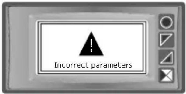
| Incorrect parameters | An error was detected in the configuration parameters of the instrument. |
| Incorrect status data | An error was detected in the saved instrument status data. |
| Eeprom reading error | An error was detected in the Eeprom memory reading sequence. |
| Eeprom writing err. | An error was detected in the Eeprom memory writing sequence. |
In all of these situations, the instrument might not be able to operate correctly. Switch it off nd back on. If the problem persists, contact assistance.
12 Configuration
12.1 Editing configuration parameters
For the configuration parameters, see par. 11
| Press Effect Execute | |||
| 1 | Confi uration | The password 0000 appears on the display with the 1^st digit selected | |
| 2 |  and and | The selected digit is modified and you go to the next by pressing | Enter the password 1234 |
| 3 |  | The names of the groups of parameters appear on the display | |
| 4 | and | Scroll the groups of parameters | |
| 5 | Sel to enter the group of parameters | The list of parameters belonging to the selected group appears on the display | and to select the parameter to be edited |
| 6 | Sel to enter parameter edit mode | The list of possible selections of the parameter or the numerical value of the parameter appear on the display | and to edit the parameter. For numerical parameters, one digit at a time can be edited by pressing Sel to confirm the change. ← to exit without editing. |
12.2 Loading default values
Entering the password 9999 loads the instrument's default settings.
As a result of this operation, the instrument is restarted so that it is initialised correctly.
12.3 Configuration via memory card
The instrument can be configured quickly via a memory card (2100.30.013). The memory card is connected to the micro-USB connector at the bottom of the instrument.
12.4 Creation of the memory card
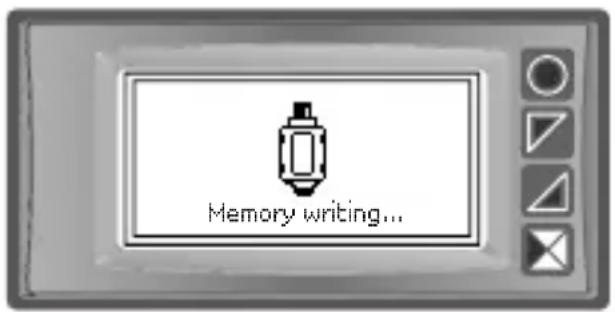
To save a configuration of parameters on the memory card, with the instrument on, connect it to the micro-USB connector, enter configuration, set the parameters necessary and exit configuration. At this point, the instrument acknowledges the presence of the memory card and saves the configuration just made on the memory card as well.
Saving is signalled by a message on the display.
12.5 Loading configuration from memory card
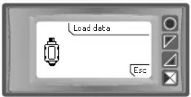
To load a configuration previously made and saved on a memory card, connect it to the micro-USB connector and power the instrument. At this point, if the memory card is detected and the data it contains are considered valid, the display will view the request for loading data from the memory card. The user can either Load data load the parameters from the memory card or Esc cancel the operation without modifying the current confi uration.
13 Configuration parameters table
The next page has the complete list of the parameters.
13.1 Display
Parameters for configuring the display.
1 Language
| Select the language |
| English (Default) |
| Italiano |
| Deutsch |
| Francais |
| Español |
2 View
Selects the viewing mode of the values of the variables used
1 value per page (Default)
2 values per page
3 values per page
4 values per page
When this parameter is set, if more variables are used that can be viewed on a page, several pages are used to complete the display of all the values.
3 Scroll time
When there are several pages of variables, automatic scrolling of the various pages can be set. This parameter sets the time interval to view each page, before switching to the next one. Time starts over when any button is pressed.
| Disabled | 4 seconds | 30 seconds |
| 1 second | 5 seconds (Default) | 1 minute |
| 2 seconds | 10 seconds | |
| 3 seconds | 20 seconds |
4 Contrast
Determines the contrast value for the OLED display. 0%..100% (Default: 100%)
5 Reverse
Enables the reverse of the OLED display. Disabled (Default) Enabled
6 Standby time
Determines the time after which the display switches to standby mode when no key has been pressed, reducing brightness so as not to be an inconvenience in environments with little lighting and to extend the display's life time.
| Always on (Default) | 1 minute | 10 minutes |
| 15 seconds | 2 minutes | 30 minutes |
| 30 seconds | 5 minutes | 1 hour |
13.2 COM1 serial port
Parameters for configuring the Modbus master serial port.
11 Mode
Selects the type of Modbus master protocol active on the COM1 serial port. Master RTU (Default) Master ASCII Multimaster RTU Multimaster ASCII
12 Multimaster address
Defines the Modbus address of the device in multimaster mode. 239..254 (Default: 254)
13 Baud rate
Selects the baud rate for serial communication
1,200 baud 9,600 baud 39,400 baud
2,400 baud 19,200 baud (Default) 57,600 bau d
4,800 baud 28,800 baud 115,200 baud
14 Serial format
Selects the format for serial communication
8,N,1 (Default) 8 bit, No parity, 1 Stop bit
8,E,1 8 bit, Even parity, 1 Stop bit
8,0,1 8 bit, Odd parity, 1 Stop bit
8,N,2 8 bit, No parity, 2 Stop bit
8,E,2 8 bit, Even parity, 2 Stop bit
8,0,2 8 bit, Odd parity, 2 Stop bit
15 Transmission delay
Defines the minimum delay in ms which the Modbus master protocol introduces between complete reception of data by the slaves and a new interrogation.
0..200 ms (Default: 2 ms)
16 Reception timeout
Defines the maximum waiting time for the response of the slaves following the interrogation before interrupting reception due to timeout. If the slave's response does not arrive within that time, the lost packs' counter is increased.
10..1000 ms (Default: 100 ms)
17 Number of errors
Defines the number of consecutive errors (reception timeout, CRC error) for each communication, after which the OFF-LINE status is signalled for the variable. At each successful communication, the off-line management error count is reset. 1..100 (Default: 10)
18 Show status
This parameter allows you to enable or disable the display of the COM1 serial port communication status. By enabling this function, the item "COM1 status" appears in the tool menu.
no..yes (Default: yes)
13.3 Variable 1..8
Parameters for configuration settings of variables 1..8.
The parameters of the variables 2..8 can be traced by adding 50 to the parameter number of variable 1 (e.g. 71 Data source). Whereas the parameters of the variable 3 can be viewed by adding 100 to the number of variable 1 (e.g. 121 Data source) and so on.
21 Data source
Defines the source of the value of the corresponding variable.
Disabled (Default var. 2..8) The variable is not managed
| COM1 serial port (Default var. 1) | The value of the variable is read/written via master serial communication or stored in the instrument. |
| Potentiometer | The variable takes on the value generated by the potentiometer |
| Digital input 1 | The variable takes on the value of the status of the digital input (0..1) |
| Digital input 2 | The variable takes on the value of the status of the digital input (0..1) |
| Digital input 3 | The variable takes on the value of the status of the digital input (0..1) |
| Alarm 1 status | The variable takes on the value of the status of the alarm (0..1) |
| Alarm 2 status | The variable takes on the value of the status of the alarm (0..1) |
| COM2 serial port | The value of the variable is written via slave serial line and does not activate the master COM1 serial port. |
22 Data format
Defines the format of the serial data relative to the variable.
| 16 bit signed (Default) | The value of the variable refers to a Modbus word interpreted as a signed data. |
| 16 bit unsigned | The value of the variable refers to a Modbus word interpreted as an unsigned data. |
| 32 bit signed | The value of the variable is managed as union of two consecutive words with sign. |
| 32 bit floating point | The value of the variable is managed as union of two consecutive words organised as data in floating point. |
| Bit 0..Bit15 | The value of the variable is managed as status of a single bit (0..1) within a 16 bit datum. |
23 Sorting
Selects the order of the words when managing 32 bit data.
| MSW first (Default) | The data consists of 2 consecutive words, the first word (lower Modbus address) is the most significant. |
| LSW first | The data consists of 2 consecutive words, the first word (lower Modbus address) is the least significant. |
24 Description
Defines the 16 character alphanumeric string used as a description when displaying the variable. The text can be freely entered one character at a time. When viewing 3 or 4 variables per page, setting the empty description (" " 16 space characters) automatically enables the "expanded" mode of the variable, namely the space intended for description is used to view the value of the variable with a larger and more legible font.
The storage of the string which contains the variable description (max 16 characters) occupies 4 consecutive parameters (24-27).
"Vx " (Default)
28 Unit of measurement
Defines the 5-character alphanumeric string used as a unit of measurement when displaying the variable. The text of the unit of measurement can be freely entered one character at a time.
The storage of the string which contains the unit of measure (max 5 characters) occupies 2 consecutive parameters (28-29).
"Ux " (Default)
30 Representation
Defines the mode in which the value of the variable will be displayed.
| Numerical (Default) | The value of the variable will be displayed in decimal numerical format. |
| Enumerative | The value of the variable is displayed using 5 mnemonic texts associated to values from 0 to 4 (max 8 characters each). The rest of the values are always viewed with the decimal representation. |
| Hidden | The variable will be regularly handled by the device, but it will not be shown on the display. |
31 Decimal point
Defines the number of decimal digits in which the value of the variable will be displayed.
| 0 (Default) no decimal | 0.0000 4 decimal digits |
| 0.0 1 decimal digit | 0.00000 5 decimal digits |
| 0.00 2 decimal digits | 0.000000 6 decimal digits |
| 0.000 3 decimal digits |
32 Lower input limit
Defines the lower limit of the variable used to enter the value.
-2147483648..2147483648 (Default: 0)
33 Upper input limit
Defines the upper limit of the variable used to enter the value. -2147483648..2147483648 (default: 1000)
34 Variation
Defines the increment/decrement value used when entering values with the arrow keys or the appropriately configured digital inputs.
-2147483648..2147483648Default: 1)
35 Processing type
Selects the type of processing which the variable value undergoes to get the value viewed on the display. On the other hand, once a new variable value is entered from the keyboard, with the inverse procedure the real value of the variable to be transferred to the remote device via serial communication will be calculated.
| None (Default) | No processing, the value of the viewed variable coincides with the actual value of the variable. |
| Gain + offset | The value of the viewed variable is calculated with the following formula: Vvis. = Vvar. * Gain + Offset |
| Rescaling | The value of the viewed variable is calculated using in the linear proportion which puts the minimum Modbus value in relation with the minimum value viewed, and the maximum Modbus value in relation with the maximum value viewed. |
36 Offset value
Defines the offset value used to calculate the value of the viewed variable if Gain + Offset is selected in the Processing type parameter.
-2147483648..2147483648 (Default: 0)
37 Gain value
Defines the Gain value used to calculate the value of the unit variable if Gain + Offset is selected in the Processing type parameter.
-1000.000..1000.000 (Default: 1.000)
38 Modbus minimum
Defines the minimum value of the Modbus variable used to calculate the value of the viewed variable if Rescaling is selected in the Processing type parameter.
-2147483648..2147483648 (Default: 0)
39 Minimum viewed
Defines the value of the viewed variable in Modbus Minimum if Rescaling, is selected in the parameter Processing type.
-2147483648..2147483648 (Default: 0)
40 Modbus maximum
Defines the maximum value of the Modbus variable used to calculate the value of the viewed variable if Rescaling is selected in the Processing type parameter.
-2147483648..2147483648 (Default: 1000)
41 Maximum viewed
Defines the value of the viewed variable in Modbus Maximum if Rescaling is selected in the Processing type parameter.
-2147483648..2147483648 (Default: 1000)
42 Refresh time
Defines the time interval with which the variable is refreshed. This interval also affects Modbus communication besides visualisation as the requests of the master to the slave devices respect this interval.
0.0..10.5 s (Default: 0.5 s)
43 Value memory
Selects whether the value of the variable must be stored in the internal memory of MA964802 in order to maintain the value even when power is missing and to re-present the last value set at the next switch-on.
| No (Default) | The value of the variable is not stored. When starting up, the variable is loaded with the value set in the Initial value parameter. |
| Yes | The value of the variable is stored in the internal memory at every change from keyboard or from appropriately confi ured digital input. When starting up, the variable is loaded with the value saved previously. |
44 Initial value
Defines the value the variable takes on when MA964802 is switched on. This parameter is only used when the Value memory parameter is set at No. -2147483648..2147483648 (Default: 0)
45 Notation
Selects the mode in which the Modbus variable address to read/write is specified and the action to carry out on this Modbus location.
| Pixsys 0..65535 (Default) | The address of the variable is set according to the numbering present on Pixsys products, namely distinguishing between bit and word data and addresses ranging from 0 to 65535. |
| Modbus 0..65535 | The address of the variable is set according to standard Modbus numbering, namely distinguishing between Coil, discrete inputs, Holding register and Input register and addresses ranging from 0 to 65535. |
| Modicon 10K.40K | The address of the variable is set according to standard Modicon numbering, where the types of Modbus data are grouped based on the address. More precisely, addresses from 1 to 9999 correspond to Coil status, addresses from 10001 to19999 correspond to Input status, addresses from 30001 to 39999 correspond to Input register and addresses from 40001 to 49999 correspond to Holding register. |
46 Slave address
Defines the address of the Modbus slave the variable refers to. The reading/writing operations relative to the variable will be executed using this address. By setting the address 0 (of course this only makes sense in case of writing), the instrument performs a broadcast writing of the variable to all devices connected to the network. For Multimaster RTU or Multimaster ASCII protocol, slave devices with a limited address range (1..238) can be connected because some addresses are used by the system to manage the multimaster protocol.
0..254 (Default: 1)
47 Data address
Defines the address of the Modbus word or bit the variable refers to. For the entry range, the setting must take into account the selection made for the Notation parameter.
0..65535 (Default: 0)
48 Action (Pixsys notation)
Selects the reading/writing action executed by the instrument using the data entered in the Slave address and Data address parameters. This parameter only takes effect if Pixsys 0..65535 is selected in the Notation parameter.
Read bit
Write bit
R/W single register
Read word (Default)
Write word
R/W multiple register
49 Action (Modbus notation)
Selects the reading/writing action executed by the instrument using the data entered in the Slave address and Data address parameters. This parameter only takes effect if Modbus 0..65535 is selected in the Notation parameter.
01 Read coils
06 Write single register
02 Read discrete input
16 Write multiple registers
03 Read holding registers (Default)
Read/Write single register
04 Read input registers
ReadWrite multiple registers
05 Write single coil
50 Action (Modicon notation)
Selects the reading/writing action executed by the instrument using the data entered in the Slave address and Data address parameters. This parameter only takes effect if Modicon 10K.40K is selected in the Notation parameter.
Read (Default)
Write single
Write multiple
Read/Write single register
Read/Write multiple registers
51 Writing mode
Selects the mode with which MA964802 manages writing on a slave device on variables which foresee writing operations of the value on a remote device.
| Continuous (Default) | The value is written on the slave continuously, regardless if changed or not. |
| Upon variation | The data is written on the slave only when the variable value is edited. |
| Upon selection | The data is written on the slave only when the variable is selected by the value taken on by the potentiometer. For further information on this mode, refer to the potentiometer management parameters. |
52 Value 0 text
Defines the text string (max 8 characters) with which the value "0" of the variable is displayed. This parameter only has meaning if Text is selected in the parameter Representation.
The storage of the string which contains the text related to value 0 (max 8 characters) occupies 2 consecutive parameters (52-53).
"0 " (Default)
54 Value 1 text
Defines the text string (max 8 characters) with which the value "1" of the variable is displayed. This parameter only has meaning if Text is selected in the Representation parameter.
The storage of the string which contains the text related to value 1 (max 8 characters) occupies 2 consecutive parameters (54-55).
"1 " (Default)
56 Value 2 text
Defines the text string (max 8 characters) with which the value "2" of the variable is displayed. This parameter only has meaning if Text is selected in the Representation parameter.
The storage of the string which contains the text related to value 2 (max 8 characters) occupies 2 consecutive parameters (56-57).
"2 " (Default)
58 Value 3 text
Defines the text string (max 8 characters) with which the value "3" of the variable is displayed. This parameter only has meaning if Text is selected in the Representation parameter.
The storage of the string which contains the text related to value 3 (max 8 characters) occupies 2 consecutive parameters (58-59).
"3 " (Default)
60 Value 4 text
Defines the text string (max 8 characters) with which the value "4" of the variable is displayed. This parameter only has meaning if Text is selected in the Representation parameter.
The storage of the string which contains the text related to value 4 (max 8 characters) occupies 2 consecutive parameters (60-61).
"4 " (Default)
13.4 Potentiometer input
Parameters for configuring the potentiometer input.
421 Minimum value
Defines the generated value of the potentiometer at the lower calibration position.
-2147483648..2147483648 (Default: 0)
422 Maximum value
Defines the generated value of the potentiometer at the upper calibration position.
-2147483648..2147483648 (Default: 100)
423 Acquisition
Selects whether or not to activate the potentiometer limits acquisition procedure. If Activated is selected, when exiting the configuration, the display will show the minimum and maximum limits acquisition procedure of the potentiometer. At the end of the procedure, the parameter is automatically set at Deactivated. (see paragraph 8.5)
Deactivated (Default)
Activated
424 Variable selection
Defines whether or not to activate the variable selection function by means of the position of the potentiometer. This function is useful to activate writing of a variable on the slave device, only when it is "selected" by the value generated by the position of the potentiometer. The values to select the variables range from 1 (variable 1 selection) to 8 (variable 8 selection). These values must therefore be entered respectively in the Minimum value and Maximum value parameters, and then the acquisition procedure must be carried out.
Deactivated (Default)
Activated
13.5 Alarm 1..2
Parameters for configuring alarms 1 and 2.
The parameters of alarm 2 can be traced by adding 20 to the parameter number of alarm 1 (e.g. 451 Alarm type).
431 Alarm type
Selects the type of alarm to manage.
Disabled (Default)
DigitalInput 1
Serial error
Absolute
Digital input 2
Remote crtl
Band
Digital input 3
432 Contact type
Selects the type of contact for the alarm output and the type of intervention.
Norm. open (Default)
N.O.-Dis.start
Norm. closed
N.C.-Dis.start
433 Alarm source
Selects the source quantity for managing the alarm
Variable 1 (Default)
Variable 4
Variable 7
Variable 2
Variable 5
Variable 8
Variable 3
Variable 6
Potentiometer
434 Alarm threshold
Determines the alarm setpoint
Lower limit..Upper limit (Default: 0)
435 Deviation threshold
Determines the deviation from the alarm setpoint for band alarms.
-2147483648..2147483648 (Default: 0)
436 Hysteresis
Determines the hysteresis value in managing absolute and band alarms.
-2147483648..2147483648 (Default: 0)
437 Alarm message
Defines the text string (max 16 characters) of the message viewed when the alarm is triggered. If you do not want to view the message, set the text as zero string (16 spaces)
"Ax " (Default)
441 Reset type
Selects the type of reset of the alarm contact.
| Automatic (Default) | Automatic reset when the alarm condition fin shes. |
| Manual | Manual reset from keyboard or from appropriately configured digital input. |
| Man. stored | Maintains the status of the relay even after a power failure. The alarm is reset manually the same way as the Manual selection. |
442 Error contact
Status of the contact if the variable selected by the parameter Alarm threshold is off-line.
Open (Default)
Closed
443 Triggering delay
Determines the delay in activating or deactivating the alarm.
-3600..3600 s (Default: 0 s)
Positive value: delay when alarm is being activated.
Negative value: delay when alarm is being deactivated.
444 Lower limit
Determines the minimum value for the alarm setpoint and for the Alarm threshold parameter.
-2147483648..2147483648 (Default: 0)
445 Upper limit
Determines the maximum value for the alarm setpoint and for the Alarm threshold parameter.
-2147483648..2147483648 (Default: 1000)
446 Protection
Selects the type of protection for the alarm set point.
Free (Default) Can be freely changed by the user.
Blocked Visible to the user but not editable.
Hidden Not visible to the user.
13.6 Digital input 1..2
Parameters for configuring digital inputs 1 and 2.
The parameters of input 2 can be traced by adding 5 to the parameter number of input 1 (e.g. 476 Input type).
471 Input type
Selects the type of hardware of the digital input.
| PNP (Default) | Input suitable for sensors with PNP outlet. It is activated by bringing the digital input to 24 Vdc (positive signal). |
| NPN | Input suitable for sensors with NPN outlet. It is activated by short circuiting the input on the exposed conductive part. |
472 Contact type
Selects the rest contact of the digital input.
Norm. open (Default) Executes the function with contact closed
Norm. closed Executes the function with contact open
473 Input function
| Selects the type of function executed by the digital input. | |
| Disabled (Default) | Decreases variable 1 |
| Enable outputs | Decreases variable 2 |
| Reset alarms | Decreases variable 3 |
| Confi uration block | Decreases variable 4 |
| Increases variable 1 | Decreases variable 5 |
| Increases variable 2 | Decreases variable 6 |
| Increases variable 3 | Decreases variable 7 |
| Increases variable 4 | Decreases variable 8 |
| Increases variable 5 | Increases selected variable |
| Increases variable 6 | Decreases selected variable |
| Increases variable 7 | Encoder editing |
| Increases variable 8 | |
13.7 Digital input 3
Parameters for configuring digital input 3.
481 Contact type
| Selects the rest contact of the digital input. |
| Norm. open (Default) Executes the function with contact closed |
| Norm. closed Executes the function with contact open |
482 Input function
| Selects the rest contact of the digital input. | |
| Disabled (Default) | |
| Variable selection | Option to connect the push contact of the panel encoder to edit the variables |
13.8 COM2 serial port
Parameters for configuring the Modbus slave serial interface.
486 Slave address
| Defines the Modbus address of the device for communication on COM2 serial port. |
| 1..254 (Default: 240) |
50 MA964802 - User manual
487 Baud rate
Selects the baud rate for serial communication
| 1,200 baud | 28,800 baud |
| 2,400 baud | 39,400 baud |
| 4,800 baud | 57,600 baud (Default) |
| 9,600 baud | 115,200 baud |
| 19,200 baud |
488 Serial format
Selects the format for serial communication
8,N,1 (Default) 8 bit, No parity, 1 Stop bit
8,E,1 8 bit, Even parity, 1 Stop bit
8,0,1 8 bit, Odd parity, 1 Stop bit
8,N,2 8 bit, No parity, 2 Stop bit
8,E,2 8 bit, Even parity, 2 Stop bit
8,0,2 8 bit, Odd parity, 2 Stop bit
489 Response delay
Defines the minimum delay in ms, which the device introduces between reception of the interrogation of the Modbus master, at the start of transmission of the response 0..100 ms (Default: 2 ms).
13.9 USB port
Parameters for configuring the USB port.
491 Mode
Defines the operating mode for the USB port.
Modbus slave (Default)
Notes / Updates


WACHENDORFF


- Introduction
- Safety standards
- Identification of the model
- Technical data
- General features
- Software features
- Dimension and installation
- Electrical connections
- For permanently connected equipment:
- Connection diagram
- 6.1.a Power supply
- 6.1.b COM1 serial port (Modbus master)
- For connection to Modbus slave devices
- 6.1.c COM2 serial port (Modbus slave)
- For connection to a Modbus master device
- 6.1.d Digital input DI.1
- Digital input DI.2
- 6.1.e Digital input DI.3
- 6.1.f Potentiometer
- For linear potentiometers.
- 6.1.g Q1 Relay Output
- 6.1.h Q2 Relay Output
- Electrical endurance Q1 / Q2.
- 6.1.i Encoder connection from panel
- Function of keys and of the display 7.1 Keys
- Display
- Display mode
- Functions of the instrument
- Displaying the variables
- Editing values of the variables
- Editing alarm thresholds
- COM1 status
- Acquisition of potentiometer limits
- Digital input 1 and 2 functions
- Digital input 3 functions
- Alarm triggering modes
- 8.8.a Absolute alarm ("Absolute" selection)
- 8.8.c Digital input alarm ("Digital input 1..3" selection)
- 8.8.d Communication alarm ("Serial error") selection
- 8.8.e Remote control alarm ("Remote ctrl" selection)
- COM1 serial port in Multimaster mode
- COM2 Serial Communication
- Notes to access parameters
- Error messages
- Configuration
- Editing configuration parameters
- Loading default values
- Configuration via memory card
- Creation of the memory card
- Loading configuration from memory card
- Configuration parameters table
- Display
- Language
- View
- Scroll time
- Contrast
- Reverse
- Standby time
- COM1 serial port
- Mode
- Multimaster address
- Baud rate
- Serial format
- Transmission delay
- Reception timeout
- Number of errors
- Show status
- Variable 1..8
- Data source
- Data format
- Sorting
- Description
- Unit of measurement
- Representation
- Decimal point
- Lower input limit
- Upper input limit
- Variation
- Processing type
- Offset value
- Gain value
- Modbus minimum
- Minimum viewed
- Modbus maximum
- Maximum viewed
- Refresh time
- Value memory
- Initial value
- Notation
- Slave address
- Data address
- Action (Pixsys notation)
- Action (Modbus notation)
- Action (Modicon notation)
- Writing mode
- Value 0 text
- Value 1 text
- Value 2 text
- Value 3 text
- Value 4 text
- Potentiometer input
- Minimum value
- Maximum value
- Acquisition
- Variable selection
- Alarm 1..2
- Alarm type
- Contact type
- Alarm source
- Alarm threshold
- Deviation threshold
- Hysteresis
- Alarm message
- Reset type
- Error contact
- Triggering delay
- Lower limit
- Upper limit
- Protection
- Digital input 1..2
- Input type
- Contact type
- Input function
- Digital input 3
- Contact type
- Input function
- COM2 serial port
- Slave address
- Baud rate
- Serial format
- Response delay
- USB port
- Mode
- Notes / Updates
- WACHENDORFF
Brand : Wachendorff
Model : MA964802
Category : Industrial digital display