
WDGA 36C - Industrial sensor Wachendorff - Free user manual and instructions
Find the device manual for free WDGA 36C Wachendorff in PDF.

| Product Type | Absolute Rotary Encoder with CANopen Interface |
| Model | WDGA 36C |
| Flange Diameter | 36 mm |
| Weight | Approx. 150 g |
| Power Supply | 10-30 V DC |
| Communication Interface | CANopen (CiA 406 profile) |
| CAN Standards | CAN 2.0A and CAN 2.0B |
| Resolution (Singleturn) | Up to 32 bits (default 4096 steps/rev) |
| Resolution (Multiturn) | Up to 17 bits (131072 revolutions) |
| Node ID Default | 127 (0x7F) |
| Baudrate | Auto-detection or configurable (10 kbit/s to 1 Mbit/s) |
| LED Indicator | Bicolor LED for status (green/red) – operational, pre-operational, stopped, error |
| Electronic Cam Switch | 8 programmable cams with low/high limits and hysteresis |
| Protection Rating | IP65 (typical for shaft encoders) |
| Operating Temperature | -40°C to +100°C |
| Connection | M12 connector or stub cable (5-pin, according to CiA 303) |
| Shaft Type | Solid or hollow bore shaft (36 mm flange) |
| Object Dictionary | Complete CiA 301/406 object dictionary with manufacturer-specific objects |
| Configuration | LSS and SDO services; EEPROM storage |
| Safety | Intended for non-safety-critical industrial applications; EMC compliance |
| Manufacturer | Wachendorff Automation |
Frequently Asked Questions - WDGA 36C Wachendorff
User questions about WDGA 36C Wachendorff
0 question about this device. Answer the ones you know or ask your own.
Ask a new question about this device
Download the instructions for your Industrial sensor in PDF format for free! Find your manual WDGA 36C - Wachendorff and take your electronic device back in hand. On this page are published all the documents necessary for the use of your device. WDGA 36C by Wachendorff.
USER MANUAL WDGA 36C Wachendorff
natural_image
Infographic with icons of construction machinery, solar panel, wind farm, and storage tanks on a blue background (no text or symbols)Technical Manual
Absolute Encoders WDGA
with CANopen interface
wachendorff-automation.com/canopen
CANopen®
Cin
EnDra®
Technologie

Imprint

natural_image
Close-up of metallic mechanical components with no visible text or symbols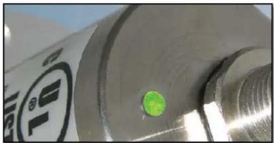
natural_image
Close-up of a metallic cylindrical component with a green circular spot and a black circular logo (no readable text or symbols)Managing Director: Robert Wachendorff
Guarantee waiver, right of amendment, copyright protection:
The company Wachendorff Automation assumes no liability and provides no guarantee for the correctness of this manual's contents or for any resulting direct or indirect damages. In the interests of continuous innovation and cooperation with our customers, we reserve the right to change technical data or content at any time.
The company Wachendorff Automation claims copyright protection for this manual. It may not be modified, extended, reproduced, or forwarded to third parties without our prior written consent.
Comments:
Should you have any suggested corrections, comments or requests for change, we invite you to submit them to us. Please send your comments to: support-wa@wachendorff.de
1 Introduction .... 1
1.1 Encoder types.... 1
1.2 About this manual.... 1
1.2.1 Symbols 2
1.3 Specifications 2
2 Safety information....3
2.1 General safety information 3
2.2 Intended use.... 3
2.3 Safe working....4
2.4 Disposal.... 4
3 Device description....5
3.1 Basic encoder design 5
3.2 Predefined Connection Settings 5
3.3 LED status indicator and signal codes....6
4 Quick start....8
4.1 CAN network integration.... 8
4.2 SDO command to set the node ID 8
4.3 Setting-up the encoder 9
5 General information about CAN 11
5.1 CAN physical and transport layer 11
5.2 CANopen....13
5.3 Specifications and profiles.... 14
5.3.1 Overview.... 14
5.3.2 Mechanisms of communication.... 14
5.3.3 Object dictionary 15
5.4 Network management (NMT) 16
5.5 Heartbeat and Node-Guarding 17
5.6 Emergency messages.... 18
6 WDGA object dictionary....19
6.1 Communication objects 19
6.2 Device specific objects 22
6.3 Manufacturer specific objects 28
7 Object description 30
7.1 Network management (NMT) commands.... 30
7.2 Heartbeat protocol.... 31
7.3 Emergency messages (EMCY) 32
7.4 Error Objects 33
7.4.1 Manufacturer status register 33
7.4.2 Alarms.... 34
7.4.3 Warnings.... 34
7.5 Electronic cam switch (CAM) 34
7.5.1 CAM-state-register 34
7.5.2 CAM-enable-register 35
7.5.3 CAM-polarity-register 35
7.5.4 CAM-Low-Limit 35
7.5.5 CAM-High-Limit 36
7.5.6 CAM-Hysteresis 36
7.6 Device profile.... 36
7.7 SYNC 36
7.8 Encoder designation.... 36
7.9 Error behaviour.... 37
7.10 NMT start-up behaviour.... 37
7.11 Bus-Off Auto-Reset 37
7.12 Customer Data 38
7.13 Temperature.... 38
7.14 Verify Configuration.... 38
8 Setting-up the encoder....39
8.1 Mechanical and electrical connection.... 39
8.2 Configuration via LSS.... 41
8.2.1 General settings.... 41
8.2.2 LSS configuration by "Switch Mode Global" 41
8.2.3 LSS configuration by "Switch Mode Selective" 42
8.2.4 End LSS configuration mode 43
8.2.5 Baudrate setting....43
8.2.6 Node-ID setting 44
8.3 Configuration via SDO 45
8.3.1 SDO access on objects.... 45
8.3.2 SDO access on objects larger than 4 bytes 47
8.3.3 Baudrate selection 54
8.3.4 Node-ID selection 55
8.3.5 Basic NMT commands.... 56
8.4 Heartbeat settings 57
8.5 PDO Configuration 57
8.5.1 PDO parameters 57
8.5.2 Synchronous PDO 59
8.5.3 Asynchronous PDO 59
8.5.4 Variable PDO-mapping 60
8.6 Changing resolution and direction 63
8.7 Position preset....64
8.8 Position value filtering.... 65
8.9 Change speed-integration and speed scaling 65
8.10 Frequency limit....66
8.11 CAM-configuration....66
8.12 Non-volatile storage of parameters.... 68
8.12.1 Saving parameters into EEPROM 68
8.12.2 Restoring default parameters from EEPROM.... 69
9 Error diagnosis....70
9.1 Encoder configurations....70
10 Support....71
Index of figures
Figure 1.1: Encoder label.... 1
Figure 3.1: Encoder versions, shaft and hollow bore shaft 5
Figure 3.2: LED indications 1....6
Figure 3.3: LED indications 2....7
Figure 5.1: Example of the arbitration.... 12
Figure 5.2: Bitstuffing....12
Figure 5.3: ISO-OSI-Modell 13
Figure 8.1: read object....45
Figure 8.2: write object 46
Figure 8.3: Segmented SDO read access 47
Figure 8.4: Initiate SDO read 48
Figure 8.5: read SDO segment.... 49
Figure 8.6: Segmented-SDO write access.... 50
Figure 8.7: Initiate SDO write....51
Figure 8.8: write SDO segment 53
Index of tables
Table 3.1: CAN-Identifier 5
Table 4.1: SYNC-message 8
Table 4.2: SDO-write command to set Node-ID 9
Table 4.3: Node-ID in decimal and hexadecimal 9
Table 5.1: CAN baud rates und recommended cable length limits.... 13
Table 5.2: Draft Standards.... 14
Table 5.3: Structure of the object dictionary 15
Table 5.4: Available communication – Pre-Operational 16
Table 5.5: Available communication – Operational.... 17
Table 5.6: Available communication – Stopped.... 17
Table 6.1: Object dictionary 1000h – 100Dh.... 19
Table 6.2: Object dictionary 1010h – 1020h ...... 20
Table 6.3: Object dictionary 1029h – 1A01h.... 21
Table 6.4: Object dictionary 1A02h – 1F80h.... 22
Table 6.5: Device specific objects 6000h –6008h.... 22
Table 6.6: Device specific objects 6009h -6310h....23
Table 6.7: Device specific objects 6311h –6322h.... 24
Table 6.8: Device specific objects 6323h -6334h.... 25
Table 6.9: Device specific objects 6335h -6504h.... 26
Table 6.10: Device specific objects 6505h -6510h....27
Table 6.11: manufacturer specific objects 2100h –2500h ...... 28
Table 6.12: manufacturer specific objects 2502h -2504h 29
Table 7.1: Structure of NMT-command....30
Table 7.2: Commands for NMT-command.... 30
Table 7.3: Node-ID values for NMT-commands 30
Table 7.4: monitor external heartbeat.... 31
Table 7.5: Example configuration of a consumer heartbeat.... 31
Table 7.6: Basic structure of an EMCY.... 32
Table 7.7: Emergency error code list.... 32
Table 7.8: Error register....32
Table 7.9: Info field list.... 33
Table 7.10: Manufacturer status register 33
Table 7.11: Alarms - Object 6503h 34
Table 7.12:Warnings – Object 6505h 34
Table 7.13: CAM-state-register – Value 89h.... 34
Table 7.14: CAM-state-register – Value 81h.... 34
Table 7.15: CAM-enable-register – Value 4Ah ...... 35
Table 7.16: Example CAM-polarity-register 35
Table 7.17: Selection of encoder reaction on errors 37
Table 7.18: Selection of start-up behaviour 37
Table 8.1: Pin and cable assignment.... 40
Table 8.2: LSS-message 41
Table 8.3: Command to set encoder "Stopped"-Mode....41
Table 8.4: LSS-Selective-Identification-Commands 42
Table 8.5: Answer of encoder to LSS-Selective-Identification-Commands...... 42
Table 8.6: End LSS configuration mode – Step 1 - store parameters.... 43
Table 8.7: End LSS configuration mode – Step 2 - Leave configuration mode...... 43
Table 8.8: set Baudrate ...... 43
Table 8.9: Baudrate-Coding.... 43
Table 8.10: Answer of LSS-slave 44
Table 8.11: set Node-ID....44
Table 8.12: Example SDO master to encoder 45
Table 8.13: Example SDO answer 45
Table 8.14: Command definitions 46
Table 8.15: Example SDO send by master.... 46
Table 8.16: Example SDO answer 46
Table 8.17: SDO read request on object 6008h 47
Table 8.18: Declaration of used abbreviations in Figure 8.4.... 48
Table 8.19: Confirm SDO read access of object 6008h....48
Table 8.20: Declaration of used abbreviations in Figure 8.5....49
Table 8.21: read of first segment 49
Table 8.22: answer with first segment 49
Table 8.23: Request next segment.... 50
Table 8.24: Answer with next segment....50
Table 8.25: SDO write access of object 6009h.... 51
Table 8.26: Acknowledgement of write access of object 6009h 51
Table 8.27: Declaration of used abbreviations in Figure 8.7....52
Table 8.28: send first segment .... 52
Table 8.29: Acknowledgement send by the encoder 52
Table 8.30: Declaration of used abbreviations in Figure 8.8....53
Table 8.31: send next segment 53
Table 8.32: Acknowledgement send by the encoder....54
Table 8.33: SDO command – set baudrate 54
Table 8.34: Baudrate-coding 54
Table 8.38: NMT command - Stop remote node.... 56
Table 8.39: NMT command - Enter Pre-Operational-state 56
Table 8.40: NMT command - Reset node communication.... 56
Table 8.41: NMT command - Reset remote node.... 56
Table 8.42: Example of heartbeat setting 57
Table 8.43: Structure of heartbeat message.... 57
Table 8.44: Heartbeat NMT-state-coding....57
Table 8.45: Default PDO configuration 57
Table 8.46: Selectable PDO transmission types.... 58
Table 8.47: PDO-Deactivation 58
Table 8.48: Example - PDO1 deactivation.... 58
Table 8.49: Parametrization of PDO1 Sub-Index 2....59
Table 8.50: Parametrization of PDO1 Sub-Index 2.... 59
Table 8.51: Parametrization of PDO1 Sub-Index 5 to 30ms....59
Table 8.52: Parametrization of PDO1 Sub-Index 2....60
Table 8.53: Parametrization of PDO1 Sub-Index 5....60
Table 8.54: Example of a mapping-table 60
Table 8.55: Structure of PDO1 (content -> Table 8.54) 61
Table 8.61: Counting direction and scaling parameters.... 63
Table 8.62: Example setting operating parameters 63
Table 8.63: Change of singleturn-resolution by SDO 64
Table 8.64: Change of total measuring range by SDO 64
Table 8.65: Set position preset 64
Table 8.66: Check current position 65
Table 8.67: Example CAM-configuration 66
Table 8.68: Enable first three cams.... 66
Table 8.69: CAM-High-Limit 1 67
Table 8.70: CAM-High-Limit 2 67
Table 8.71: CAM-High-Limit 3 67
Table 8.72: CAM-Low-Limit 1 67
Table 8.73: CAM-Low-Limit 2 67
Table 8.74: CAM-Low-Limit 3 67
Table 8.75: Saving parameters....68
Table 8.76: Example – Save all parameters.... 68
Table 8.77: Restoring parameters 69
Table 9.1: Error diagnosis – Encoder configuration.... 70
List of abbreviations
| autom. | automatic |
| approx. | approximately |
| CAN | Controller Area Network |
| CAN-ID | Main part of the arbitration of a CAN-frame |
| co | constant: parameter is read-only, doesn't change |
| COB-ID | Communication Object identifier, specifying the CAN-ID and additional parameters for the related communication object |
| comp. | Compare |
| DLC | Data Length Code |
| DS | Draft Standard |
| DSP | Draft Standard Proposal |
| dyn | dynamic; information changes depending on encoder features |
| EDS file | Electronic data sheet, standardised file describing a CANopen device |
| EMC | Electromagnetic Compatibility |
| Encoder | here synonym for absolute rotary encoder |
| e.g. | for example (exempli gratia) |
| etc. | et cetera, and so on |
| GND | Ground |
| i* | Wildcard character for encoder specific information |
| i.e. | that is (id est) |
| Idx | Sub-Index |
| LED | Light Emitting Diode |
| LSB | Least Significant Bit/Byte |
| LSS | Layer Setting Services |
| MSB | Most Significant Bit/Byte |
| MT | Multiturn |
| n.n. | not necessary |
| NMT | Network management |
| Node-ID | Part of CAN-ID; number of the encoder in the CAN network |
| OSI | Open Systems Interconnection Reference Model |
| p. | Page reference |
| PDO | Process Data Object. Communication object for transmission of process data |
| res.ro | reservedRead Only: but not constant |
| RTR | Remote Transmission Request |
| rw | Read/Write: parameter can be read and written |
| SDO | Service Data Object; communication object providing access to all entries of the object dictionary |
| ST | Singleturn |
| SYNC | Synchronisations telegram |
| wo | Write Only |
| xxb | Mark that (xx) is a binary representation |
| xxd | Mark that (xx) is a decimal representation |
| xxh | Mark that (xx) is a hexadecimal representation |
1 Introduction
1.1 Encoder types
This manual is assigned to the following Wachendorff Automation encoders:
WDGA CANopen
It applies to all WDGA CANopen with Revision Number (Software version) 2.08 and less.
The Wachendorff Automation CANopen vendor id is: 0100 021Fh
The Wachendorff Automation product code is: WDGA= 5744 4741h
The revision number and the serial number vary for each individual encoder and can be found on the encoder's label:
Figure 1.1: Encoder label
In the figure 1.1 the revision number is marked blue (here: 1.00). The revision is combined with a leading 0306 and fixed within the encoder firmware (e.g. Rev. 1.00 = 0306 0100h; Rev. 2.08 = 0306 0208h).
The serial number is marked green (here: "12345656"). This decimal value transferred into "hex" is used in the firmware (e.g. "12345656"="00BC 6138"h).
The hardware version is marked red (here: AA). The ASCII value transferred into hex is the hardware revision coded in the corresponding CANopen object.
1.2 About this manual
This technical manual describes the configuration and mounting possibilities for absolute-value encoders with a CANopen interface produced by Wachendorff Automation. It supplements the other publicly available Wachendorff automation documents, e.g. data sheets, assembly instructions, leaflets, catalogues and flyers.
Ensure that you read the manual before commissioning — check beforehand that you have the latest version of the manual.
When reading, pay particular attention to the information, important notices and warnings that are marked with the corresponding symbols (see 1.2.1).
Section 4 Quick start shows a way how to configure the encoder in a very general setting with minimal functionality. For optimal usage of the device, it is necessary to read all the following information. Abbreviations and specific wording is explained at the beginning of this manual.
This manual is intended for persons with technical knowledge in the handling of sensors, CANopen interfaces and automation elements. If you do not have any experience in this field, request the assistance of experienced personnel before proceeding.
Keep the information provided with our product in a safe place so that you can refer to it at a later date as necessary.
1.2.1 Symbols
 | The INFO symbol indicates a section that contains particularly important information for advanced use of the device. |
 | The IMPORTANT symbol is shown next to a section of text that describes a method for solving a particular problem. |
 | The WARNING symbol indicates that the adjacent instructions must be observed to ensure correct use of the device and to protect the user against hazards. |
1.3 Specifications
An encoder is a sensor that is designed to detect angular positions (singleturn) and revolutions (multiturn). The measured data and variables are processed by the encoder and provided as electrical output signals for the connected peripherals.
The interface and protocol for the communication between encoder and attached equipment meets the CAN and CANopen specifications. The encoder is capable of CAN 2.0A and CAN 2.0B. The implemented CANopen protocol meets the CiA 406 encoder profile.
For an easy configuration of the encoder, EDS files (electronic data sheet) are provided at the download area at www.wachendorff-automation.com.
2 Safety information
2.1 General safety information

- When commissioning the encoder, ensure that you observe the assembly instructions, manual and data sheet.
- Failure to observe the safety instructions may lead to malfunctions, property damage and personal injury!
- Observe the operating instructions provided by the machine's manufacturer.
2.2 Intended use
Rotary encoders are components that are intended for installation in machines. Before commissioning (operation in accordance with the intended use), it must be determined that the machine as a whole corresponds to the EMC and Machine Directive.
A rotary encoder is a sensor that is designed to detect angular positions and revolutions and must only be used for this purpose! Wachendorff Automation manufactures and distributes encoders for use in non-safety-relevant industrial applications.

- The encoder must not be operated outside the specified limit parameters (see data sheet).
2.3 Safe working
The installation and mounting of the encoder must only be carried out by a qualified electrician.
For the construction of electrical installations, all relevant national and international regulations must be strictly observed.
Failure to commission the encoder correctly may result in malfunction or failure.

- All electrical connections must be tested before commissioning.
- Appropriate safety measures must be taken to ensure that no persons are harmed and no damage to the system or operating equipment occurs in the event of a failure or malfunction.
2.4 Disposal
Devices that are no longer needed or are defective must be disposed by the user in proper compliance with the country-specific laws. It must be taken into consideration that this is a special waste of electronics and that disposal is not permitted via normal household waste.
There is no obligation by the manufacturer to take the device back. If you have any questions regarding proper disposal, contact a disposal specialist in your area.
3 Device description
3.1 Basic encoder design
Wachendorff Automation WDGA encoders are available in different mechanical versions. Key features are size and shape. The standard sizes are 36mm and 58mm flange diameter. Different types of shapes according to shafts and flanges are available. Examples of the different versions are shown in Figure 3.1:
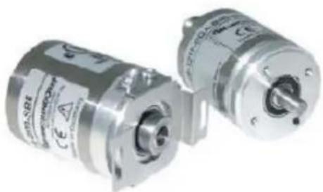
natural_image
Two metallic industrial sensors with visible branding and mounting bracket (no readable text or symbols)Figure 3.1: Encoder versions, shaft and hollow bore shaft
The shaft or the hollow bore shaft will be connected to the rotating part of which the angular position or rotation you want to measure. The encoder itself is mounted by several tapped bores or torque supports.
A stub cable or M12 sized connector provides the electrical connection to the CAN-network.
A bicolour status LED at the top indicates the different states of the encoder during use and helps with configuration and troubleshooting.
3.2 Predefined Connection Settings
| Services | COB-ID |
| NMT | 000h |
| SYNC | 080h |
| EMCY | 080h + Node-ID |
| PDO1(tx) | 180h + Node-ID |
| PDO2(tx) | 280h + Node-ID |
| PDO3(tx) | 380h + Node-ID |
| SDO(rx) | 600h + Node-ID |
| SDO(rx) | 580h + Node-ID |
Table 3.1: CAN-Identifier
By default all WDGA encoders are set on Node-ID=127h and Baudrate=Auto-Detection.
3.3 LED status indicator and signal codes
Definition of LED indication types:
● = red LED indications = "Physical Layer" information
= green LED indications = "NMT-Status" information
● = LED off
→ = continue like first cycle
LED-Indications [ms]:
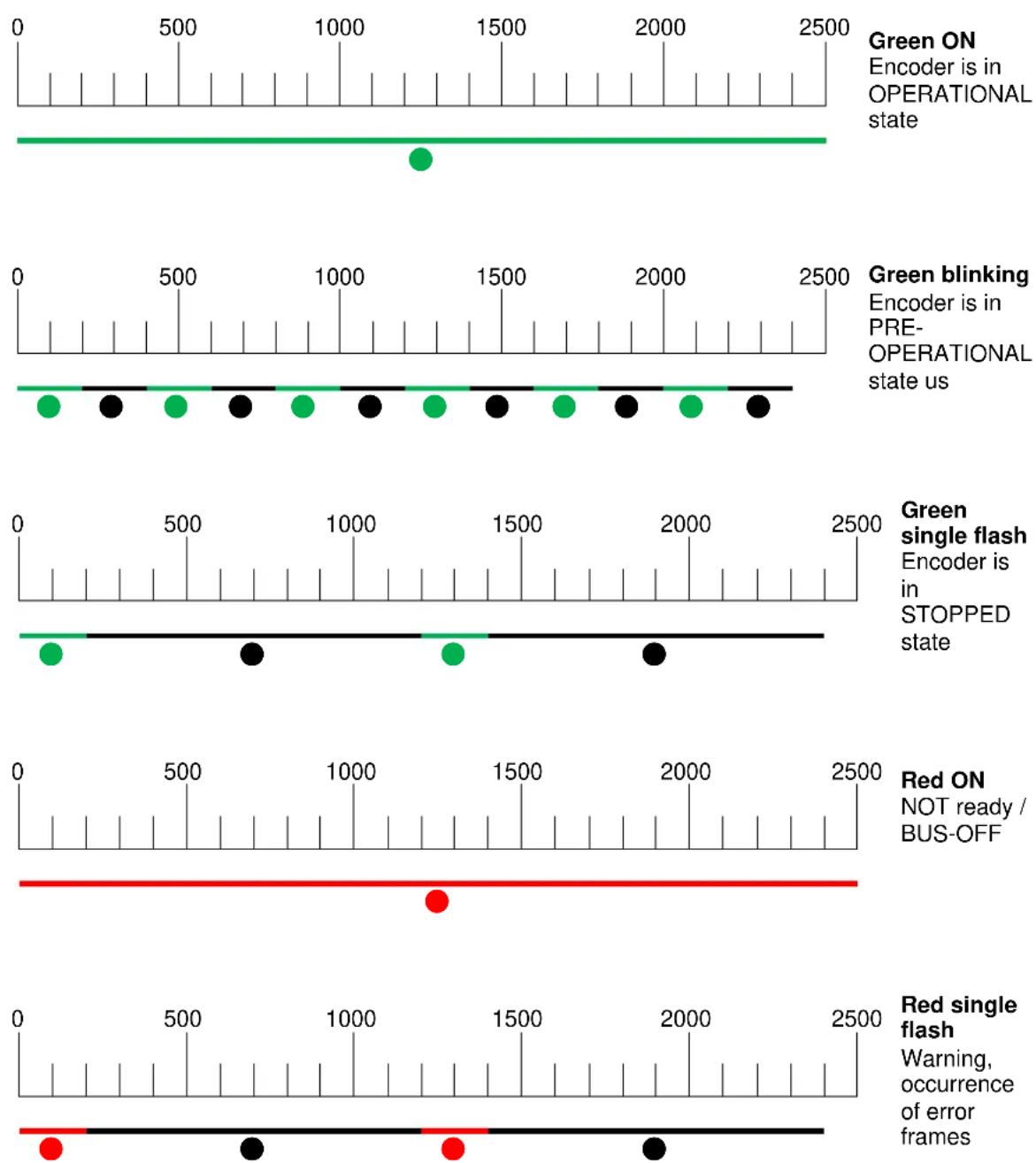
Green ON
Encoder is in OPERATIONAL state
Green blinking
Encoder is in PRE- OPERATIONAL state us
Green
single flash
Encoder is in STOPPED state
Red ON
NOT ready / BUS-OFF
Red single flash
Warning, occurrence of error frames
Figure 3.2: LED indications 1
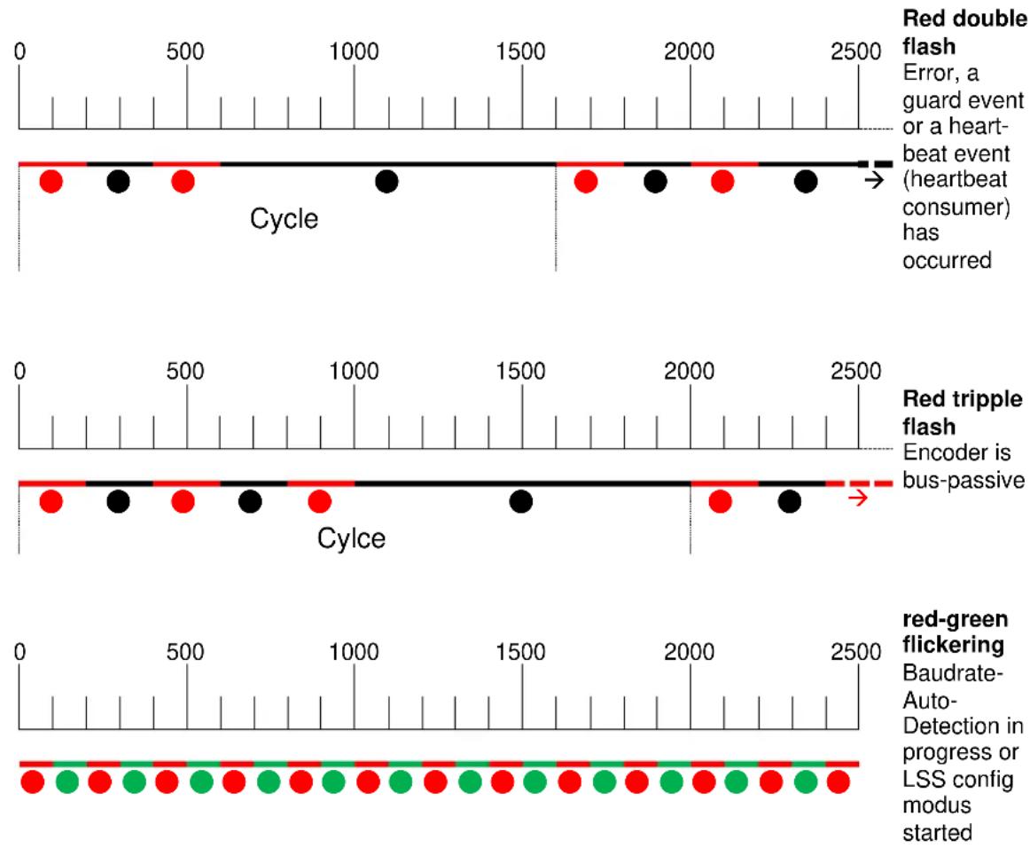
Error, a guard event or a heart-beat event (heartbeat consumer) has occurred
Encoder is bus-passive
Baudrate-Auto-Detection in progress or LSS config modus started
Figure 3.3: LED indications 2
4 Quick start

- The encoder indicates every status modification with its status-LED. See chapter 3.3 "LED status indicator and signal codes".
4.1 CAN network integration
The default node ID of Wachendorff Automation encoders (Object 2101h sub-Index: 00h) is 7Fh=127d.
For operating in a CAN-Network, the encoder's baudrate has to be set. The common ways to set the baudrate is via LSS (CiA DSP-305) or a SDO command.
Wachendorff Automation WDGA encoders have the capability to detect the baudrate of the network automatically (object 2100h sub-Index: 00h value: 09h - Baudrate-auto-detection). So usually the baudrate setup is not necessary. To detect the valid baudrate the encoder stays passive and scans the communication at the bus. When the baudrate is detected, the encoder is set to this rate, sends its boot-up message and switches into pre-operational mode.
To prevent possible collisions in case double assigned node ID it is recommended to use a 1:1 connection with a bus master for configuration (e.g. a laptop computer with suitable hard- and software). Set the master on the intended baudrate and use SDO or LSS services to configure the encoder.
4.2 SDO command to set the node ID
After connecting the encoder WDGA with the CAN bus respectively the master (e.g. a laptop computer with suitable hard- and software) the LED starts "flickering red and green" (see Figure 3.3 LED indications 2).
First send one or more SYNC messages, which the encoder can use to detect the baudrate:
| 080h | 8 | 00h | 00h | 00h | 00h | 00h | 00h | 00h | 00h |
| CAN-ID | DLC | Command | Byte0 | Byte1 | Byte2 | Byte3 | Byte4 | Byte5 | Byte6 |
Table 4.1: SYNC-message
The encoder will detect and lock on the used baudrate. It will send its boot-up message and the LED starts to blink green (see Figure 3.2).
To set the encoders node ID the object 2101h, Sub-Index 00h has to be accessed. (Only possible in PRE-OPERATIONAL state!) Send a write-SDO-command with the intended node ID (in hex):
| 600h+ID | 8 | 2Fh | 01h | 21h | 00h | Node-ID | 00h | 00h | 00h |
| CAN-ID | DLC | Command | Object L | Object H | Sub-Index | Byte0 | Byte1 | Byte2 | Byte3 |
Table 4.2: SDO-write command to set Node-ID
An example for a node ID might be:
| Node-ID (d) | Node-ID (h) |
| 1 | 01h |
| 2 | 02h |
| ... | ... |
| 4 | 04h |
| ... | ... |
| 127 | 7Fh |
Table 4.3: Node-ID in decimal and hexadecimal
The change of the node ID via SDO will be effective after a reset of the encoder (hard reset or NMT reset). The new node ID is stored into the EEPROM immediately and without a further command. The setting of the node ID via LSS is described in chapter 8.

- Changing the Node ID automatically adjusts the PDO and EMCY COB IDs. After the first manual storage, they are frozen at their current value and no longer automatically adjusted. Performing the "Restore Defaults" command will re-enable automatic adjustment.
4.3 Setting-up the encoder
Connect the encoder to the bus of application. Please mind the included mounting and safety advice documents. You can find additional information to this in chapter 8 "Setting-up".
When the encoder is completely integrated into the application you can switch it into OPERATIONAL mode by the "Start-All-Nodes-Command" (see chapter 7.1).
The encoder is now operational (LED shows green ON) and starts sending its data via the several process data objects (PDO). The encoders default configuration plans that the PDO1 is triggered once the position value changes.
The position value (object 6004h) is mapped in PDO1 and transmitted as an Unsigned32. By default PDO2 transmits the same value but synchronously on the reception of a SYNC message. Heartbeat is switched off and will not be transmitted by default. The encoder is now configured and ready for basic applications.
5 General information about CAN
5.1 CAN physical and transport layer
CAN is a field bus. It operates with the CSMA/CA (Carrier Sense Multiple Access / Collision Avoidance) method. It means that collisions during bus access are avoided by a so called bitwise arbitration. The bits are coded NRZ-L (Non Return to Zero - Low).
A cyclic redundancy check (CRC) and other safety mechanisms provide a secure transmission. For synchronisation a mechanism called "bit stuffing" is used. CAN is a multi-master system, i.e. several equal bus nodes can be connected without a bus master supervising the communication. In principle a CAN bus can be realized with copper wire or in fibre optic cable.
The common CAN implementation with copper wire operates with differential signals, transmitted via two wires: CAN HIGH , CAN LOW . Therefore CAN has a good common mode rejection ratio.
Data is transmitted with bits that can either be dominant or recessive. The dominant (0) always overwrites the recessive (1).
The topology of a CAN network is a line, which can be extended by stubs. The maximum length of a stub is limited to 0,5m.
The network always has to be terminated on both ends with 120Ohms each (between CAN HIGH und CAN LOW ). Other locations or values are not allowed.
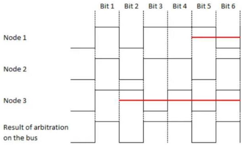
The arbitration mentioned before is used to control the bus access of the nodes by prioritization of the CAN-Identifier of the different messages. Every node monitors the bus. If more than on node wants access on the bus, the node with the highest priority of the messages ID succeeds and the other nodes retreat until there is "silence" on the bus (see Figure 5.1). Technically the first dominate bit of the ID send overwrites the corresponding recessive bit of the other IDs. In case that more than one node uses the same CAN-ID an error occurs only at a collision within the rest of the frame. On principle a CAN-ID should only be used by a single node!
other
| Node | Bit 1 | Bit 2 | Bit 3 | Bit 4 | Bit 5 | Bit 6 | |--------|-------|-------|-------|-------|-------|-------| | Node 1 | Yes | No | Yes | No | Yes | No | | Node 2 | Yes | No | Yes | No | Yes | No | | Node 3 | Yes | Yes | Yes | No | Yes | No | | Result of arbitration on the bus | Yes | Yes | Yes | Yes | Yes | Yes |Figure 5.1: Example of the arbitration
Due to the arbitration there is a ranking of the messages. The message with the lowest ID has the highest priority and therefore it has almost instant access on the bus. The exception is that an ongoing transmission will not be interrupted. So time critical messages should be assigned to the high priority CAN-IDs, but even then there is no determination in the time of transmission (non-deterministic transmission).
For the arbitration all nodes have to be synchronised. Due to the lack of a separate clock signal, the transmission of many identical bits in line would lead to the loss of synchronisation. The so called bit-stuffing is used to prevent this case. After five equal bits a complementary bit will be inserted into the transmission (the application will not notice). So the nodes can keep up resynchronising on the bit flanks (see Figure 5.2).
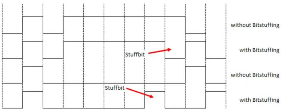
Figure 5.2: Bitstuffing
A CAN network can operate with baud rates up to 1 Mbit/s. Due to the necessary synchronisation of the nodes, the maximum delay caused by the length of the cable has to be limited. The limitation corresponds with the baudrate. There is a common recommendation of the maximum cable length at several baud rates.
Table 5.1: CAN baud rates and recommended cable length limits
5.2 CANopen
CANopen is a specified higher protocol (layer 7 protocol) (Figure 5.3).

bar
| Application-Service | 1. Physical Layer | 2. Data Link Layer | 3. Network Layer | 4. Transport Layer | 5. Session Layer | 6. Presentation Layer | 7. Application Layer | |---|---|---|---|---|---|---|---| | Transport-Service | | | | | | | | | | | | | | | | |With CANopen it is possible to transfer larger amounts of data, emergency telegrams and process data. CANopen describes how the communication is performed. That means that parameters to configure a device are transmitted in a defined form (profile).
A CANopen profile defines objects representing the different functions of a device. These objects form a table called object dictionary.
The communication profile defines the basic services and parameters of a CANopen device (e.g. service data objects SDOs, process data objects PDOs, used CAN-IDs, etc.).
The device profile defines the specific functions of a device family (e.g. encoders, i/o devices, ...). For encoders the device profile is the encoder profile CiA 406.
5.3 Specifications and profiles
5.3.1 Overview
The CANopen specifications were defined by the CiA in Draft Standards. Concerning the WDGA encoders the following specifications are from special importance:
| Specification | Description |
| CiA 301 | Application Layer and Communication Profile |
| CiA 303 | Cabling/pin assignment, Representation of units, Indicator specification |
| CiA 305 | Configuration of baudrate und node ID via LSS |
| CiA 306 | Electronic Data Sheet |
| CiA 406 | Device-/Application-profile |
Table 5.2: Draft Standards
5.3.2 Mechanisms of communication
There are several different CANopen communication services:
SDO Service Data Object
Use: for access to the object dictionary. There is one single SDO-channel.
Two identifiers are assigned to the SDO channel, one for each direction of transmission.
For SDO the 8 byte CAN frame is divided into 1 byte command, a multiplexor of 2 byte index and 1 byte sub index of the object dictionary, and 4 byte of payload. For bigger payloads either segmented or block transfer is used.
A SDO transmission will always be acknowledged by the receiver. In case of a failure an "abort message" is send. The internal delay time of the WDGA encoders is 1 millisecond maximum.
PDO Process Data Object
Use: for transmission of process data. The WDGA encoders provide up to four PDOs. A PDO uses the full length of the data area of a CAN frame (8 bytes) for the process data without additional overhead.
PDOs will not be acknowledged and are suitable for time critical applications.
By using the full 8 bytes for data, there is no additional information about transmitted objects. Therefore the PDO producer and the PDO consumer have to define the PDO-mapping.
PDOS can be sent on different ways:
- On request: A node sends a RTR frame to ID of the designated PDO and the encoder returns the PDO. (The CiA strongly recommends not to use RTR frames. Therefore RTR is not supported by Wachendorff Automation encoders!)
- Synchronously: On the reception of a SYNC message the node send its PDOs.
- Asynchronously: The sending of the PDOs is triggered by an internal event (e.g. the internal event timer).
5.3.3 Object dictionary
The object dictionary lists all data types, objects and functions of the communication and the device profile. There are also manufacturer specific objects listed. The objects are addressed by 16-bit indices (lines) and 8-bit sub-indices (columns).
Table 5.3 shows the structure of the object dictionary:
| Index(hex) | Object description |
| 0000 | reserved |
| 0001 001F | static data types |
| 0020 003F | complex data types |
| 0040 005F | manufacturer specific data types |
| 0060 007F | profile specific static data types |
| 0080 009F | profile specific complex data types |
| 00A0 0FFF | reserved |
| 1000 1FFF | communication profile objects |
| 2000 5FFF | manufacturer specific objects |
| 6000 9FFF | objects from the "Standard device profiles" |
| A000 AFFF | network variables |
| B000 FFFF | reserved / system variables |
Table 5.3: Structure of the object dictionary
5.4 Network management (NMT)
A CANopen network always needs a network management master. The NMT master controls the NMT states of all connected nodes.
A node can be switched into three different states:
- Pre-Operational
- Operational
- Stopped

- After a CANopen node is switched on and the communication and the internal application is initialised, the node switches into pre-operational state. From this state the NMT-Master can switch the node into the other states. To show that a node is ready after boot up, it sends a "boot-up message". These messages uses the CAN-ID of the Emergency service (EMCY). The message is permanently associated with the node ID.
Description of the NMT-states:
| Pre-Operational | |
| Object | Communication enabled |
| SDO | yes |
| PDO | no |
| NMT | yes |
| SYNC | no |
| EMCY | yes |
| Heartbeat | yes |
| SDO communication is enabled.PDO communication is disabled. | |
| Operational | |
| Object | Communication enabled |
| SDO | yes |
| PDO | yes |
| NMT | yes |
| SYNC | yes |
| EMCY | yes |
| Heartbeat | yes |
| Device is in operational status and can send and receive PDOs. | |
Table 5.4: Available communication – Pre-Operational
Table 5.5: Available communication – Operational
| Stopped | |
| Object | Communication enabled |
| SDO | no |
| PDO | no |
| NMT | yes |
| SYNC | no |
| EMCY | no |
| Heartbeat | yes |
| The communication is almost completely disabled.The device only reacts on NMT commands (e.g. start node). | |
Table 5.6: Available communication – Stopped
5.5 Heartbeat and Node-Guarding
There are two possible ways to supervise the operational availability of a CAN node during operation.
- Heartbeat
- Node-Guarding
The heartbeat protocol is independent from the master. It is the recommended mechanism. The device sends autonomous and cyclic a "life" message.

- Wachendorff Automation recommends the use of the heartbeat protocol.
When using the node guarding protocol, the NMT master sends RTR frames to the slaves, which have to answer within a defined time. If the answer is missing, this is detected by the master. This protocol leads to a high dependence on the master.

- A variation of the Heartbeat is the Bootup-Message. This type is sent out once the encoder is started and includes no information (Data is 00h). Only by interpreting the COB-ID of the message, the senders Node-ID is obvious (COB-ID = 700h + Node-ID).
5.6 Emergency messages
Failures of a CAN node are announced by emergency messages (EMCY message). The EMCY message contains an error code identifying the problem. A node also can be configured to send no EMCYs.
6 WDGA object dictionary
6.1 Communication objects
The communication objects comply with the CiA specification 301 v4.02 and have the object addresses 1000h to 1FFFh.
| Object No. | Name | Sub Idx | Function | Data type | ro rw co | Map | Default value |
| 1000h p. 36 | Device type | 0h | (MSB) Encoder type (LSB) device profile no. | Unsigned32 | co | no | Multiturn: 0002 0196h Singleturn: 0001 0196h |
| 1001h p. 32 | Error Register | 0h | Indication of internal failures and part of an emergency object | Unsigned8 | ro | yes | 00h |
| 1002h p. 33 | Manufacturer status register | 0h | General status register for manufacturer specific purpose | Unsigned32 | ro | yes | dyn. |
| 1003h | Predefined Error Field | 00h | stores occurring errors indicated by EMCY; volatile; | Unsigned8 | rw | no | dyn. |
| 01h | Standard error field 1 | Unsigned32 | ro | ||||
| 02h | Standard error field 2 | Unsigned32 | ro | ||||
| 03h | Standard error field 3 | Unsigned32 | ro | ||||
| 04h | Standard error field 4 | Unsigned32 | ro | ||||
| 05h | Standard error field 5 | Unsigned32 | ro | ||||
| 1005h p. 36 | COB-ID SYNC-Message | 00h | COB-ID of the SYNC message | Unsigned32 | rw | no | 0000 0080h |
| 1008h p. 36 | Manufacturer device name | 00h | Manufacturer device name | string256 | co | no | WDGA-ST-CO WDGA-MT-CO |
| 1009h | Manufacturer Hardware-Version | 00h | Contains the hardware revision assigned by the manufacturer. | string16 | co | co | i* |
| 100Ah | Manufacturer Software-Version | 00h | Contains the software revision assigned by the manufacturer. | string72 | co | no | i* |
| 100Ch | Guard time | 00h | Defines the guard time in Milliseconds; 0h= node guard protocol disabled. | Unsigned16 | rw | no | 0000h |
| 100Dh | Life time factor | 00h | Contains the life time factor for the node guard protocol. | Unsigned8 | rw | no | 00h |
| 1010h p. 68 | Store Parameters | 00h | Unsigned8 | co | no | 04h | |
| 01h | Save all parameters | Unsigned32 | rw | 0000 0001h | |||
| 02h | Save communication param. | Unsigned32 | rw | 0000 0001h | |||
| 03h | Save application param. | Unsigned32 | rw | 0000 0001h | |||
| 04h | Save manufacturer param. | Unsigned32 | rw | 0000 0001h | |||
| 1011h p. 69 | Restore default Parameters | 00h | Restores factory settings. | Unsigned8 | co | no | 04h |
| 01h | Restore all param. | Unsigned32 | rw | 0000 0001h | |||
| 02h | Restore communication param. | Unsigned32 | rw | 0000 0001h | |||
| 03h | Restore application param. | Unsigned32 | rw | 0000 0001h | |||
| 04h | Restore manufacturer param. | Unsigned32 | rw | 0000 0001h | |||
| 1014h p. 32 | COB-ID Emergency object | 00h | Defines the COB-ID of the emergency object (EMCY). | Unsigned32 | rw | no | 0000 0080h+ Node-ID |
| 1015h p. 33 | Inhibit time EMCY | 00h | Defines the minimum pause (in 100 μs steps) between single EMCYs | Unsigned16 | rw | no | 0000h |
| 1016h p. 31 | Consumer heartbeat time | 00h | Defines the time frame within the heartbeat consumer awaits an incoming heartbeat otherwise triggering an EMCY. | Unsigned8 | co | no | 01h |
| 01h | Heartbeat-Consumer cycle time | Unsigned32 | rw | 0000 0000h | |||
| 1017h p. 31 | Producer heartbeat time | 00h | Defines the heartbeat cycle time in steps of 1 ms. 0h = heartbeat disabled. | Unsigned16 | rw | no | 0000h |
| 1018h p. 1 | Identity Object | 00h | Unsigned8 | co | no | 04h | |
| 01h | Vendor-ID | Unsigned32 | co | 0100 021Fh | |||
| 02h | Product Code | Unsigned32 | co | 5744 4741h | |||
| 03h | Revision Number | Unsigned32 | i* | ||||
| 04h | Serial Number | Unsigned32 | i* | ||||
| 1020h p. 38 | Verify Configura-tion | 00h | The time of the last configuration can be logged here. If the configuration was changed after setting this value, the object is set to zero autonomously. | Unsigned8 | co | no | 02h |
| 01h | Configuration date | Unsigned32 | rw | 0000 0000h | |||
| 02h | Configuration time | Unsigned32 | rw | 0000 0000h | |||
| 1029h p. 37 | Error behaviour | 00h | Changing the encoders behaviour in case of a node-guarding or heartbeat event, etc. | Unsigned8 | co | no | 02h |
| 01h | Communication error | Unsigned8 | rw | 00h | |||
| 02h | Encoder Error | Unsigned8 | rw | 00h | |||
| 1800h p. 57 | Transmit PDO1 com-munication parameter | 00h | Defines the communication parameters of the 1st TPDO | Unsigned8 | co | no | 05h |
| 01h | COB-ID or PDO | Unsigned32 | rw | 180h + Node-ID | |||
| 02h | Transmission Type | Unsigned8 | rw | FEh | |||
| 05h | Event-Timer | Unsigned16 | rw | 0000h | |||
| 1801h p. 57 | Transmit PDO2 com. parameter | 00h | Defines the com. parameters of the 2nd TPDO | Unsigned8 | co | no | 05h |
| 01h | COB-ID for PDO | Unsigned32 | rw | 280h + Node-ID | |||
| 02h | Transmission Type | Unsigned8 | rw | 01h | |||
| 05h | Event-Timer | Unsigned16 | rw | 0000h | |||
| 1802h p. 57 | Transmit PDO3 com. parameter | 00h | Defines the com. parameters of the 3rd TPDO | Unsigned8 | co | no | 05h |
| 01h | COB-ID for PDO | Unsigned32 | rw | 380h + Node-ID | |||
| 02h | Transmission Type | Unsigned8 | rw | 01h | |||
| 05h | Event-Timer | Unsigned16 | rw | 0000h | |||
| 1803h p. 57 | Transmit PDO4 com. parameter | 00h | Defines the com. parameters of the 4th TPDO | Unsigned8 | co | no | 05h |
| 01h | COB-ID for PDO | Unsigned32 | rw | 480h + Node-ID | |||
| 02h | Transmission Type | Unsigned8 | rw | 01h | |||
| 05h | Event-Timer | Unsigned16 | rw | 0000h | |||
| 1A00h p. 61 | TPDO1 mapping parameter | 00h | Defines the PDO-mapping of the 1st TPDO | Unsigned8 | rw | no | 01h |
| 01h | Mapped application object 1 | Unsigned32 | rw | 6004 0020h | |||
| variable, depends on sub-index 00h | 02h - 08h | Mapped application object 2 - 8 | Unsigned32 | rw | |||
| 1A01h p. 61 | TPDO2 mapping parameter | 00h | Defines the PDO-mapping of the 2nd TPDO | Unsigned8 | rw | no | 01h |
| 01h | Mapping von Objekt 1 in der Applikation | Unsigned32 | rw | 6004 0020h | |||
| variable, depends on sub-index 00h | 02h - 08h | Mapped application object 2 - 8 | Unsigned32 | rw | |||
| 1A02h p. 61 | TPDO3 mapping parameter | 00h | Defines the PDO-mapping of the 3rd TPDO | Unsigned8 | rw | no | 01h |
| 01h | Mapped application object 1 | Unsigned32 | rw | 6008 0020h | |||
| variable, depends on sub-index 00h | 02h - 08h | Mapped application object 2 - 8 | Unsigned32 | rw | |||
| 1A03h p. 61 | TPDO4 mapping parameter | 00h | Defines the PDO-mapping of the 4th TPDO | Unsigned8 | rw | no | 00h |
| variable, depends on sub-index 00h | 01h - 08h | Mapped application object 1 - 8 | Unsigned32 | rw | |||
| 1F80h p. 37 | NMT-Start-up-behaviour | 00h | Defines the start-up behaviour of encoder | Unsigned32 | rw | no | 0000 0000h |
Table 6.1: Object dictionary 1000h – 100Dh
Table 6.2: Object dictionary 1010h – 1020h
Table 6.3: Object dictionary 1029h – 1A01h
Table 6.4: Object dictionary 1A02h - 1F80h
(p. = page reference; ro / rw / co = access type; Map = PDO-Mapping; i* = individual; dyn = dynamic; ST = singleturn; MT = multiturn)
6.2 Device specific objects
The device specific objects comply with the CiA encoder profile specification 406 v3.2 and have the object addresses range 6000h to 9FFFh.
| Object No. | Name | Sub Idx | Function | Data type | ro rw co | Map | Default value |
| 6000h p. 63 | Operating Parameters | 00h | Changing / Indicating the operating parameters | Unsigned16 | rw | no | 0004h |
| 6001h p. 64 | Measuring units per revolution | 00h | Changing / Indicating the singleturn resolution (STR) | Unsigned32 | rw | no | 0000 4000h |
| 6002h p. 64 | Total measuring range | 00h | Changing / Indicating the total measuring range | Unsigned32 | rw | no | i* |
| 6003h p. 64 | Preset value | 00h | Setting / Indicating the preset value to adapt the position value to the application | Unsigned32 | rw | no | 0000 0000h |
| 6004h | Position value | 00h | current position value | Unsigned32 | ro | yes | dyn |
| 6008h | High precision position value | 00h | Current position value, when measuring range >32 bit | Unsigned64 | ro | yes | dyn |
| 6009h | High precision Preset Value | 00h | Setting/indicating the High-precision-preset-value. Access via segmented or block transfer | Unsigned64 | rw | no | 0000 0000 0000 0000h |
| 6030h | Speed Value | 00h | Rotation speed in units (bit) per second | Unsigned8 | ro | yes | 01h |
| 01h | Speed value | Signed16 | ro | dyn | |||
| 6040h | Acceleration Value | 00h | Acceleration value in units(bit) per second2 | Unsigned8 | ro | yes | 01h |
| 01h | Acceleration value | Signed16 | ro | dyn | |||
| 6050h | Jerk Value | 00h | Jerk value in units (bit) per second3 | Unsigned8 | ro | yes | 01h |
| 01h | Jerk value | Signed16 | ro | dyn | |||
| 6200h | Cyclic-Timer | 00h | Changing / Indicating the transmission period of asynchronous TPDOs | Unsigned16 | rw | no | 0001h |
| 6300h p. 34 | CAM state register | 00h | Status bits of the cams of the corresponding cam channel | Unsigned8 | ro | yes | 01h |
| 01h | Cam state channel1 0b=inactive 1h=active | Unsigned8 | ro | 00h | |||
| 6301h p. 35 | CAM enable register | 00h | Changing / Indicating the cam enable bits of the corresponding cam channel | Unsigned8 | ro | no | 01h |
| 01h | Cam enable channel1 0b=inactive 1b=active | Unsigned8 | rw | 00h | |||
| 6302h p. 35 | CAM polarity register | 00h | Changing / Indicating the inversion of the corresponding cam in (6300h) | Unsigned8 | ro | no | 01h |
| 01h | Cam polarity channel1 0b=cam state not inverted / 1b=cam state inverted | Unsigned8 | rw | 00h | |||
| 6310h | CAM1 low limit | 00h | Indicating the lower switching point of the 1st cam | Unsigned8 | co | no | 01h |
| 01h | Changing lower switching point CAM1 | Signed32 | rw | 0000 0000h | |||
| 6311h | CAM2 low limit | 00h | Indicating the lower switching point of the 2nd cam | Unsigned8 | co | no | 01h |
| 01h | Changing lower switching point CAM2 | Signed32 | rw | 0000 0000h | |||
| 6312h | CAM3 low limit | 00h | Indicating the lower switching point of the 3rd cam | Unsigned8 | co | no | 01h |
| 01h | Changing lower switching point CAM3 | Signed32 | rw | 0000 0000h | |||
| 6313h | CAM4 low limit | 00h | Indicating the lower switching point of the 4th cam | Unsigned8 | co | no | 01h |
| 01h | Changing lower switching point CAM4 | Signed32 | rw | 0000 0000h | |||
| 6314h | CAM5 low limit | 00h | Indicating the lower switching point of the 5th cam | Unsigned8 | co | no | 01h |
| 01h | Changing lower switching point CAM5 | Signed32 | rw | 0000 0000h | |||
| 6315h | CAM6 low limit | 00h | Indicating the lower switching point of the 6th cam | Unsigned8 | co | no | 01h |
| 01h | Changing lower switching point CAM6 | Signed32 | rw | 0000 0000h | |||
| 6316h | CAM7 low limit | 00h | Indicating the lower switching point of the 7th cam | Unsigned8 | co | no | 01h |
| 01h | Changing lower switching point CAM7 | Signed32 | rw | 0000 0000h | |||
| 6317h | CAM8 low limit | 00h | Indicating the lower switching point of the 8th cam | Unsigned8 | co | no | 01h |
| 01h | Changing lower switching point CAM8 | Signed32 | rw | 0000 0000h | |||
| 6320h | CAM1 high limit | 00h | Indicating the upper switching point of the 1st cam | Unsigned8 | co | no | 01h |
| 01h | Changing upper switching point CAM1 | Signed32 | rw | 0000 0000h | |||
| 6321h | CAM2 high limit | 00h | Indicating the upper switching point of the 2nd cam | Unsigned8 | co | no | 01h |
| 01h | Changing upper switching point CAM2 | Signed32 | rw | 0000 0000h | |||
| 6322h | CAM3 high limit | 00h | Indicating the upper switching point of the 3rd cam | Unsigned8 | co | no | 01h |
| 01h | Changing upper switching point CAM3 | Signed32 | rw | 0000 0000h | |||
| 6323h | CAM4 high limit | 00h | Indicating the upper switching point of the 4th cam | Unsigned8 | co | no | 01h |
| 01h | Changing upper switching point CAM4 | Signed32 | rw | 0000 0000h | |||
| 6324h | CAM5 high limit | 00h | Indicating upper switching point CAM5 | Unsigned8 | co | no | 01h |
| 01h | Changing upper switching point CAM5 | Signed32 | rw | 0000 0000h | |||
| 6325h | CAM6 high limit | 00h | Changing / Indicating the upper switching point of the 6th cam | Unsigned8 | co | no | 01h |
| 01h | Changing upper switching point CAM6 | Signed32 | rw | 0000 0000h | |||
| 6326h | CAM7 high limit | 00h | Changing / Indicating the upper switching point of the 7th cam | Unsigned8 | co | no | 01h |
| 01h | Changing upper switching point CAM7 | Signed32 | rw | 0000 0000h | |||
| 6327h | CAM8 high limit | 00h | Changing / Indicating the upper switching point of the 8th cam | Unsigned8 | co | no | 01h |
| 01h | Changing upper switching point CAM8 | Signed32 | rw | 0000 0000h | |||
| 6330h | CAM1 hysteresis | 00h | Indicating the hysteresis for the 1st cam | Unsigned8 | co | no | 01h |
| 01h | Changing the hysteresis for the 1st cam | Unsigned32 | rw | 0000 0000h | |||
| 6331h | CAM2 hysteresis | 00h | Indicating the hysteresis for the 2nd cam | Unsigned8 | co | no | 01h |
| 01h | Changing the hysteresis for the 2nd cam | Unsigned32 | rw | 0000 0000h | |||
| 6332h | CAM3 hysteresis | 00h | Indicating the hysteresis for the 3rd cam | Unsigned8 | co | no | 01h |
| 01h | Changing the hysteresis for the 3rd cam | Unsigned32 | rw | 0000 0000h | |||
| 6333h | CAM4 hysteresis | 00h | Indicating the hysteresis for the 4th cam | Unsigned8 | co | no | 01h |
| 01h | Changing the hysteresis for the 4th cam | Unsigned32 | rw | 0000 0000h | |||
| 6334h | CAM5 hysteresis | 00h | Indicating the hysteresis for the 5th cam | Unsigned8 | co | no | 01h |
| 01h | Changing the hysteresis for the 5th cam | Unsigned32 | rw | 0000 0000h | |||
| 6335h | CAM6 hysteresis | 00h | Indicating the hysteresis for the 6th cam | Unsigned8 | co | no | 01h |
| 01h | Changing the hysteresis for the 6th cam | Unsigned32 | rw | 0000 0000h | |||
| 6336h | CAM7 hysteresis | 00h | Indicating the hysteresis for the 7th cam | Unsigned8 | co | no | 01h |
| 01h | Changing the hysteresis for the 7th cam | Unsigned32 | rw | 0000 0000h | |||
| 6337h | CAM8 hysteresis | 00h | Indicating the hysteresis for the 8th cam | Unsigned8 | co | no | 01h |
| 01h | Changing the hysteresis for the 8th cam | Unsigned32 | rw | 0000 0000h | |||
| 6400h | Area state register | 00h | Indicating if the current position is in or outside the work area | Unsigned8 | co | yes | 01h |
| 01h | Status of the area state register: 00h=within area; 03h=outside work area 05h=outside work area | Unsigned8 | ro | dyn | |||
| 6401h | Work area low limit | 00h | Number of sub- indices | Unsigned8 | co | no | 01h |
| 01h | Changing / Indicating the work area low limit | Signed32 | rw | 0000 0000h | |||
| 6402h | Work area high limit | 00h | Number of sub- indices | Unsigned8 | co | no | 01h |
| 01h | Changing / Indicating the work area high limit | Signed32 | rw | 0000 4000h | |||
| 6500h | Operating- status | 00h | Indicates the operating state of the device | Unsigned16 | ro | no | dyn |
| 6501h | Measuring units per revolution | 00h | Indication of the singleturn resolution | Unsigned32 | co | no | 0000 4000h |
| 6502h | Number of distinguishable revolutions | 00h | Indication of the multiturn resolution | Unsigned16 | co | no | ST: 0001h MT: FFFFh |
| 6503h p. 34 | Alarms | 00h | Alarm set by malfunction. | Unsigned16 | ro | yes | dyn |
| 6504h | Supported alarms | 00h | Information about supported alarms. | Unsigned16 | co | no | 0001h |
| 6505h p. 34 | Warnings | 00h | Warning set on deviation of certain parameters. | Unsigned16 | ro | yes | dyn |
| 6506h | Supported warnings | 00h | Information about supported warnings. | Unsigned16 | co | no | 7001h |
| 6507h | Profile and software version | 00h | Revision of the implemented encoder profile and software | Unsigned32 | co | no | 0105 0302h |
| 6508h | Operating time | 00h | not supported | Unsigned32 | co | no | FFFF FFFFh |
| 6509h | Offset value | 00h | Offset value, calculated from the preset value (6003h) | Signed32 | ro | no | 0000 0000h |
| 650Ah | Module identification | 00h | Manufacturer specific offset | Unsigned8 | co | no | 03h |
| 01h | Manufacturer offset value | Signed32 | co | 00h | |||
| 02h | Manufacturer min.-position | Signed32 | co | - | |||
| 03h | Manufacturer max.-position | Signed32 | co | - | |||
| 650Bh | Serial number | 00h | serial number of the encoders, hard wired with object 1018h-04h | Unsigned8 | co | no | 01h |
| 01h | Serial number | Unsigned32 | co | i* | |||
| 6510h | Number of high-precision-revolutions | 00h | Indicates the maximum possible high-precision multiturn resolution | Unsigned40 | co | no | 0080 0000 0000h |
Table 6.5: Device specific objects 6000h –6008h
Table 6.6: Device specific objects 6009h-6310h
Table 6.7: Device specific objects 6311h-6322h
Table 6.8: Device specific objects 6323h-6334h
Table 6.9: Device specific objects 6335h-6504h
Table 6.10: Device specific objects 6505h – 6510h
(p. = page reference; ro / rw / co = access type; Map = PDO-Mapping; i* = individual; dyn = dynamic; ST = singleturn; MT = multiturn)
6.3 Manufacturer specific objects
The objects 2000h to 5FFFh are manufacturer specific and not defined by the CiA.
| Object No. | Name | Sub Idx | Function | Data type | ro rw co | Map | Default value |
| 2100h p. 54 | Baudrate | 00h | Setting the baudrate | Unsigned8 | rw | no | 09h |
| 2101h p. 55 | Node-ID | 00h | Setting the node-ID | Unsigned8 | rw | no | 7Fh |
| 2103h p. 37 | BUS-Off Auto-Reset | 00h | Defines the time in BUS OFF, before automatically resetting. 0h = no automatic reset, 01h-FFh = time in sec. | Unsigned8 | rw | no | 00h |
| 2105h p. 65 | Integration value | 00h | Number of values for filtering speed, acceleration and jerk | Unsigned8 | rw | no | 02h |
| 01h | Integration-Position value filter | Unsigned8 | rw | 01h | |||
| 02h | Integration-Speed value filter | Unsigned32 | rw | 03E8h | |||
| 2106h p. 65 | Speed scaling | 00h | Speed value scaling | Unsigned8 | co | no | 02h |
| 01h | Multiplier | Unsigned16 | rw | 0001h | |||
| 02h | Divisor | Unsigned16 | rw | 0001h | |||
| 2107h p. 66 | Frequency-Limit | 00h | Limit for Speed value | Unsigned16 | rw | no | FFFFh |
| 2120h p. 38 | Customer EEPROM area | 00h | Object to store any customer data. | Unsigned8 | co | no | 08h |
| 01h | Customer data 1 | Unsigned32 | rw | FFFF FFFFh | |||
| 02h | Customer data 2 | Unsigned32 | rw | FFFF FFFFh | |||
| 03h | Customer data 3 | Unsigned32 | rw | FFFF FFFFh | |||
| 04h | Customer data 4 | Unsigned32 | rw | FFFF FFFFh | |||
| 05h | Customer data 5 | Unsigned32 | rw | FFFF FFFFh | |||
| 06h | Customer data 6 | Unsigned32 | rw | FFFF FFFFh | |||
| 07h | Customer data 7 | Unsigned32 | rw | FFFF FFFFh | |||
| 08h | Customer data 8 | Unsigned32 | rw | FFFF FFFFh | |||
| 2500h p. 38 | Temperature Object | 00h | Monitoring the internal operating temperature | Unsigned8 | co | yes | 05h |
| 01h | Current temperature value | Signed16 | ro | dyn | |||
| 02h | Upper Limit | Signed16 | rw | 100 (°C) | |||
| 03h | Lower Limit | Signed16 | rw | -40 (°C) | |||
| 04h | Maximum value occurred | Signed16 | ro | dyn | |||
| 05h | Minimum value occurred | Signed16 | ro | dyn | |||
| 2502h | Error History | 00h | Non-volatile error history. | Unsigned32 | co | no | dyn |
| 01h | Standard Error field 1 | Unsigned32 | ro | dyn | |||
| 02h | Standard Error field 2 | Unsigned32 | ro | dyn | |||
| 03h | Standard Error field 3 | Unsigned32 | ro | dyn | |||
| 04h | Standard Error field 4 | Unsigned32 | ro | dyn | |||
| 05h | Standard Error field 5 | Unsigned32 | ro | dyn | |||
| 2503h | Alarms- History | 00h | Logging of alarms occurred.Number of alarms. | Unsigned8 | co | no | dyn |
| 01h | Alarm 1 | Unsigned16 | ro | dyn | |||
| 02h | Alarm 2 | Unsigned16 | ro | dyn | |||
| 03h | Alarm 3 | Unsigned16 | ro | dyn | |||
| 04h | Alarm 4 | Unsigned16 | ro | dyn | |||
| 05h | Alarm 5 | Unsigned16 | ro | dyn | |||
| 2504h | Warnings- History | 00h | Logging of warnings occurred. Number of warnings. | Unsigned8 | rw | no | dyn |
| 01h | Warning 1 | Unsigned16 | ro | dyn | |||
| 02h | Warning 2 | Unsigned16 | ro | dyn | |||
| 03h | Warning 3 | Unsigned16 | ro | dyn | |||
| 04h | Warning 4 | Unsigned16 | ro | dyn | |||
| 05h | Warning 5 | Unsigned16 | ro | dyn |
Table 6.11: manufacturer specific objects 2100h –2500h
Table 6.12: manufacturer specific objects 2502h-2504h
(p. = page reference; ro / rw / co = access type; Map = PDO-Mapping; i* = individual; dyn = dynamic; ST = singleturn; MT = multiturn)
7 Object description
7.1 Network management (NMT) commands
To switch between the encoders states (STOPPED, PRE-OPERATIONAL, OPERATIONAL) or to trigger a soft reset, there are different NMT commands. The messages are 3 bytes each and will not be acknowledged. The CAN-ID of the NMT is always ZERO and therefore has the highest priority.
Table 7.1: Structure of NMT-command
Command:
The command determines the intended reaction of the addressed node.
| Command | Wert |
| Start Node | 01h |
| Stop Node | 02h |
| Pre-Operational | 80h |
| Reset Node | 81h |
| Reset Communication | 82h |
Table 7.2: Commands for NMT-command
Node-ID:
The node-ID determines, whether the NMT addresses a certain node or all nodes.
| Command | Wert |
| all Nodes | 00d |
| Valid Nod-IDs | 01..127d |
| invalid Node-IDs | 128..255d |
Table 7.3: Node-ID values for NMT-commands
7.2 Heartbeat protocol
By default the heartbeat protocol is disabled.
The encoder can either send a heartbeat (producer heartbeat) or monitor the heartbeat of other nodes (consumer heartbeat):
Producer heartbeat (Encoder sends its heartbeat)
The producer heartbeat can be enabled by setting the producer heartbeat time in milliseconds respectively can be disabled by setting the producer heartbeat time to 00h. This is done by object 1017h, sub-index 0 (00h=OFF, time in milliseconds = 0..9999h).
Consumer Heartbeat (Encoder monitors an external heartbeat)
The object 1016h, sub-Index=01h, defines the consumer heartbeat time. The encoder uses this time to monitor another heartbeat producer. If the monitored heartbeat does not occur within this time (e.g. device broken), the encoder sends an EMCY message with error code 8130h (Life guard or heartbeat error).
The object also defines the node-ID to be monitored.
| Bit 31-24 | Bit 23 -16 | Bit 15 – 0 |
| reserved (00h) | Node-ID | Heartbeat Producer time |
Table 7.4: monitor external heartbeat
A time value of 0 or a node value 0 or higher than 127 disables the function.
Example for monitoring the node 127d =7Fh with a heartbeat consumer time of 10000 milliseconds (=2710h). The WDGA is assumed to be node 1:
| 601h | 8 | 23h | 16h | 10h | 01h | 10h | 27h | 7Fh |
| CAN-ID | DLC | Command | Object L | Object H | Sub-Index | Time L | Time H | Producer Node-ID |
Table 7.5: Example configuration of a consumer heartbeat
7.3 Emergency messages (EMCY)
An emergency is sent when a failure occurs either on the bus or within the device. Within an EMCY message the error is coded.
Object 1014h defines the COB-ID of the emergency message. The default value is 80h + device node-ID (1 - 127). BasicCAN Frames or ExtendedCAN Frames can be used (Bit 29 = 1).
General structure of an emergency message:
| 80h+ID | 8 | Error Code L | Error Code H | Error Reg. | Info1 | Info2 |
| CAN-ID | DLC | Byte0 | Byte1 | Byte2 | Byte3 | Byte4 |
Table 7.6: Basic structure of an EMCY
| Error Code (H,L) | Description |
| 0000h | no error |
| 4200h | Temperature out of tolerance |
| 5000h | Hardware failure (EEPROM) |
| 8110h | CAN overrun |
| 8120h | CAN Error passive state |
| 8130h | Heartbeat / Life guarding error |
| 8140h | Bus Off recovery |
Table 7.7: Emergency error code list
Error register:
Interpretation of object 1001h (bit interpretation, default = 00000000):
| Bit: | 7 | 6 | 5 | 4 | 3 | 2 | 1 | 0 |
| Info: | co | co | co | Communication | Temperature | co | co | Generic error |
Table 7.8: Error register
List info field:
The info field depends on the error codes:
| Error Code | Field | Bit | Hex-value | Error description |
| 4200h | Info field 1 (Byte3) | 6 | 40h | Temp. Read Error |
| 5 | 20h | low limit exceeded | ||
| 4 | 10h | high limit exceeded |
| Error Code | Field | Bit | Hex-value | Error description |
| 5000h | Info field 2 (Byte4) | 0 | 01h | EEPROM error in init-phase |
| 3 | 08h | EEPROM Write-Timeout | ||
| 8120h + 8100h | Info field 1 (Byte3)Low Nibble | 0 | 1h | active, no Error |
| 1+2 | 6h | Bus-Warning | ||
| 0+1+2 | 7h | Bus-Passive | ||
| 8120h + 8100h | Info field 1 (Byte3)High Nibble | 0 | 1h | Bit |
| 1 | 2h | Stuffing-Error | ||
| 0+1 | 3h | Form | ||
| 2 | 4h | CRC | ||
| 0+2 | 5h | Ack |
Table 7.9: Info field list
The low nibble describes the CAN state, the high nibble gives further information about the error.
The transmission of EMCY messages can be disabled by setting bit 31 (MSB) in object 1014h-00h.
By changing 1015h a minimum pause between two EMCYs can be defined (in steps of 100µs ).
7.4 Error Objects
7.4.1 Manufacturer status register
Interpretation of object 1002h (assignment bit - meaning, standard = 00h):
| Bit: | 7 | 6 | 5 | 4 | 3 | 2 | 1 | 0 |
| Info: | co | co | co | co | co | EEPROM* | MT* | ST*(1) |
| Bit: | 15 | 14 | 13 | 12 | 11 | 10 | 9 | 8 |
| Info: | ST*(8) | ST*(7) | ST*(6) | ST*(5) | ST*(4) | ST*(3) | ST*(2) | ST*(1) |
| Bit: | 23 | 22 | 21 | 20 | 19 | 18 | 17 | 16 |
| Info: | ST*(15) | ST*(14) | ST*(13) | ST*(12) | ST*(11) | ST*(10) | ST*(9) | ST*(8) |
| Bit: | 31 | 30 | 29 | 28 | 27 | 26 | 25 | 24 |
| Info: | MT*(9) | MT*(8) | MT*(7) | MT*(6) | MT*(5) | MT*(4) | MT*(3) | MT*(2) |
Table 7.10: Manufacturer status register
* = Error type (number) | for detailed definitions please contact our technical support.
7.4.2 Alarms
Interpretation of object 6503h
(assignment bit - meaning, standard = 000000000000000):
| Bit: | 15..1 | 0 |
| Info: | co | Position Error |
Table 7.11: Alarms - Object 6503h
7.4.3 Warnings
Interpretation of object 6505h
(assignment bit - meaning, standard = 000000000000000):
| Bit: | 15 | 14 | 13 | 12 | 11..1 | 0 |
| Info: | co | Temp. read failed | Undertemp. | Overtemp. | co | Frequency limit |
Table 7.12: Warnings – Object 6505h
7.5 Electronic cam switch (CAM)
Encoders by Wachendorff Automation provide the possibility to configure an electronic cam switch with 8 cams in one single channel. Every cam is defined by its low and high limit, the hysteresis and the polarity.
7.5.1 CAM-state-register
The cam state register (object 6300h) represents the state of the 8 cam switches, one bit per cam. For example the cam state register has the value of 89h:
| Position | 7(MSB) | 6 | 5 | 4 | 3 | 2 | 1 | 0(LSB) |
| Type | CAM 8 | CAM 7 | CAM 6 | CAM 5 | CAM 4 | CAM 3 | CAM 2 | CAM 1 |
| Value | 1 | 0 | 0 | 0 | 1 | 0 | 0 | 1 |
| Logic | High | Low | Low | Low | High | Low | Low | High |
Table 7.13: CAM-state-register – Value 89h
That means that the cams 1, 4 and 8 are high and the rest are low. If e.g. the cam 4 toggles to low due to the change of the position value, the cam state register would become 81h:
| Position | 7(MSB) | 6 | 5 | 4 | 3 | 2 | 1 | 0(LSB) |
| Type | CAM 8 | CAM 7 | CAM 6 | CAM 5 | CAM 4 | CAM 3 | CAM 2 | CAM 1 |
| Value | 1 | 0 | 0 | 0 | 0 | 0 | 0 | 1 |
| Logic | High | Low | Low | Low | Low | Low | Low | High |
Table 7.14: CAM-state-register – Value 81h
The cams are independent to each other so the cam state register can take on 256 combinations to control a machine.
7.5.2 CAM-enable-register
Each cam can separately be enabled or disabled by the object 6301h sub-Index 01h. The cams are represented by the bits of the object, 1 = ON, 0 = OFF. For example CAM 2, CAM 4 and CAM 7 shall be enabled, so the configuration is:
| Position | 7(MSB) | 6 | 5 | 4 | 3 | 2 | 1 | 0(LSB) |
| Type | CAM 8 | CAM 7 | CAM 6 | CAM 5 | CAM 4 | CAM 3 | CAM 2 | CAM 1 |
| Value | 0 | 1 | 0 | 0 | 1 | 0 | 1 | 0 |
Table 7.15: CAM-enable-register – Value 4Ah
That means writing 4h to object 6301h sub-index 01h. The cams 2, 4 and 7 are now enabled and can switch depending on their configured limits and the position value.
7.5.3 CAM-polarity-register
The cam-polarity-register object 6302h sub-index 01h alters the polarity of the corresponding cam states in cam state register. By default all cams are high (=1b) when the position value is within the limits of the cam.
E.g. if the cam polarity register is set to 13h (=00010011b) the cams 1, 2 and 6 are inverted (Bit = 0b (Low), while position value inside limits).
| Position | 7(MSB) | 6 | 5 | 4 | 3 | 2 | 1 | 0(LSB) |
| Type | CAM 8 | CAM 7 | CAM 6 | CAM 5 | CAM 4 | CAM 3 | CAM 2 | CAM 1 |
| Value | 0 | 0 | 0 | 1 | 0 | 0 | 1 | 1 |
| Logic | Default | Default | Default | Inverted | Default | Default | Inverted | Inverted |
Table 7.16: Example CAM-polarity-register
7.5.4 CAM-Low-Limit
The object CAM-Low-Limit sets the lower switching position for a cam. Each cam has its own CAM-low-limit object. (See object dictionary 6310h...6317h). Within the low-limit objects the sub index represents a cam channel. WDGA provides one channel with 8 cams.

- The cam-high-limit always has to be lower than the corresponding low-limit. Therefore the high-limit must be usually configured before the corresponding low-limit!
7.5.5 CAM-High-Limit
The CAM-High-Limit defines the upper switching position for a cam, similar to the CAM-low-limit. Therefore each cam has its own high-limit-object (see object dictionary 6320h .. 6327h).
7.5.6 CAM-Hysteresis
The CAM-Hysteresis defines the width of the cam hysteresis for each single cam (see object dictionary 6320h...6327h).
7.6 Device profile
Object 1000h provides the number of the implemented device profile and the device type:
- 0001 0196h – singleturn encoder DS-406 device profile
- 0002 0196h – multiturn encoder DS-406 device profile
7.7 SYNC
1005h is the selected COB-ID on which the encoder awaits the SYNC message. BasicCAN frames and ExtendedCAN frames (Bit 29 = 1b) are supported. The encoder is a SYNC consumer, not a producer!
7.8 Encoder designation
Object 1008h delivers the encoder designation. Only sub index 0 is supported. The value of this object depends on the variant of the firmware.
• WDGA-ST-CO - singleturn CANopen
• WDGA-MT-CO - multiturn CANopen
7.9 Error behaviour
On a CAN communication error an OPERATIONAL encoder switches into PREOPERATIONAL. The behaviour on CAN bus errors can be changed by object 1029h sub-index 01h and the behaviour on encoder errors can be changed by sub-index 02h.
The following values are valid on sub-index 01h and 02h:
| Value | Description |
| 00h | Default behaviour, go PRE-OPERATIONAL |
| 01h | Do not change current NMT state |
| 02h | Go STOPPED |
Table 7.17: Selection of encoder reaction on errors
7.10 NMT start-up behaviour
Index 1F80h determines the encoders NMT-start-up behaviour (only sub-index 0 is supported):
There are 3 options:
| Value | Description |
| 00h | Default behaviour, go PRE-OPERATIONAL |
| 02h | Send NMT-command "Start All Nodes" |
| 08h | Go "OPERATIONAL" |
Table 7.18: Selection of start-up behaviour
By sending a "start all nodes" the encoder takes the task of a basic NMT master. The configuration has to be saved into the EEPROM.
7.11 Bus-Off Auto-Reset
Index 2103h configures the encoder behaviour when it enters Bus-off state. The default value "0" means that the encoder will remain bus-off until reset. By changing this value the time can be configured in seconds after which the encoder will automatically switch to CAN-Error Active. This feature has to be used with caution, because it can have a critical impact on the whole bus system!
7.12 Customer Data
The object 2120h provides the possibility to store up to 8 data objects (4 byte per object) into the internal EEPROM. Each data is accessed by a sub-index (1...8). The data is stored autonomous, a "save" command is not necessary.
7.13 Temperature
The 2500h provides the current internal temperature of the encoder, as well as the possibility to set temperature limits for the device. Sub-indices 0 to 5 are supported. The temperature value is updated every minute. The unit is °C. Crossing the temperature limits will set the error register (object 1001h-00h) to 1000b (=08h) and trigger a non-recurring EMCY message. The warning object (6505h) will also be effected. By default the limits are set to the maximum values allowed, but can be tightened.
7.14 Verify Configuration
You can write the time of the last valid configuration into object 1020h.
This object is also readable. Any change in the configuration will automatically reset this object to zero. Then the new time of configuration can be set.

- All change in parameters, unless otherwise specified, have to be saved into the EEPROM, e.g. by using the "Store All Parameters" command (see 8.12 "Saving parameters into EEPROM"). Otherwise the encoder will return to the last configuration saved after a reset.
8 Setting-up the encoder
8.1 Mechanical and electrical connection

- For mechanical and electrical connection please mind the included mounting instructions and information.
Shaft encoders:

- Always use a suitable coupling to connect the encoder shaft with the application shaft. The coupling compensates the radial and axial tolerances of both shafts. Both shafts must not touch each other. Please mind the maximal permitted load of the shafts. Suitable accessories can be found on www.wachendorff-automation.com.
- Use the threaded bores to screw the encoder flange onto a suitable mounting.
- Another possibility for mounting is the use of clamping claws.
Hollow bore (blind) encoders:

- Stick the encoder completely onto the application shaft. Use the set screw to arrest the encoder shaft with the application shaft.
- The encoder has a mounted torque support. This torque support has to be screwed to the machine. The torque support is elastic so that vibrations and tolerances of the application shaft will not overload the encoder's bearings.
Use the M12 sensor connector or the stub cable to connect the encoder with the bus. We recommend the use of a T-adapter. Terminations and other accessories are also available at www.wachendorff-automation.com.
Pin assignment (according to CiA 303):
(Variations possible (e.g. 58V))
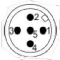 | ||
| Definition | Wire colour (Encoder with cable) | Pin (Encoder with connector) |
| Supply UB(10-30V) | brown | 2 |
| Ground (GND) | white | 3 |
| CANHigh | green | 4 |
| CANLow | yellow | 5 |
| CANGND | grey | 1 |
Table 8.1: Pin and cable assignment
8.2 Configuration via LSS
8.2.1 General settings
The Layer Setting Services Protocol is specified in the Draft Standard Proposal 305. The LSS allows to configure the encoder even when the node ID is not assigned correctly (e.g. the default node ID doesn't match the application before configuration). The WDGA encoder provides the following LSS services:
- Switch state global
- Switch state selective
- Configure baudrate service
- Configure node-ID service
- Store configuration service
- Identification and inquire services (Node-ID, Vendor-ID, Product code, Revision number, Serial number)
A LSS message has the following form:
For the CAN-ID applies:
• LSS-Master -> LSS-Slave: 2021(7E5h)
• LSS-Slave ) -> LSS-Master: 2020(7E4h)
To use LSS the encoder has to be STOPPED or PRE-OPERATIONAL. Then the encoder can be set into LSS mode by two ways:
- Switch Mode Global
- Switch Mode Selective
8.2.2 LSS configuration by "Switch Mode Global"
Connect the LSS master with the encoder. If possible start encoder before master. The baudrate used by the master will be detected by the encoder. Use the NMT command to switch the encoder into "STOPPED" mode. Send the following message:
Table 8.3: Command to set encoder "Stopped"-Mode
The encoder is now in configuration mode and now you can configure baudrate and node ID of the encoder via LSS (see section 8.2.5 and 8.2.6).
8.2.3 LSS configuration by "Switch Mode Selective"
Connect the LSS master with the encoder. If possible start encoder before master. The baudrate used by the master will be detected by the encoder. Use the NMT command to switch the encoder into "STOPPED" mode. With the switch mode selective a certain device can be selected by sending four identification messages:
| LSS-Command | Information | Description |
| 40h | Vendor-ID | 0100 021Fh |
| 41h | Product code | 5744 4741h |
| 42h | Revision number | Revision of encoder |
| 43h | Serial number | Serial number of encoder |
Table 8.4: LSS-Selective-Identification-Commands
Detailed information about revision number and serial number can be found in chapter 1 "Introduction".
After the last of the four identification messages was send, the appendant encoder will respond with:
| LSS-Command | Information | Description |
| 44h | Mode | Mode = 1 -> Configuration modeMode = 0 -> Operation mode |
Table 8.5: Answer of encoder to LSS-Selective-Identification-Commands
The encoder is now in configuration mode. Now you can set the encoders baudrate and node ID using LSS (see chapter 8.2.5 und 8.2.6).
 | • As soon as the encoder has entered the LSS configuration mode (selective or global) baudrate and node ID can be changed by LSS. After changing the settings have to be stored and the configuration mode has to be deactivated. (see below "End LSS configuration mode"). |
8.2.4 End LSS configuration mode
When the configuration is completed the changed parameters must be stored and the encoder has to be switched into PRE-OPERATIONAL state by using the following message sequence and a final reset (e.g. a power reset):
Step 1 - store parameters:
To set the baudrate send the following command:
| 7E5h | 13h | 00h | Baudrate | 00h | 00h | 00h | 00h | 00h |
| CAN-ID | Command | Sub-Index | Baudrate | Byte2 | Byte3 | Byte4 | Byte5 | Byte6 |
Table 8.8: set Baudrate
The following baud rates can be selected:
Check the LSS slaves answer to the command above:
| 7E4h | 13h | 00h | 00h | 00h | 00h | 00h | 00h | 00h |
| CAN-ID | Command | Error Code | Specific Error | Byte2 | Byte3 | Byte4 | Byte5 | Byte6 |
Table 8.10: Answer of LSS-slave
Error Code:
- 00h = OK
- 01h = Baudrate not supported
Specific Error:
- 00h = OK
• FFh = Application specific error
Possibly the communication with the encoder fails after the configuration because the configuration tool and the encoder might operate on different baud rates, so you have to change the baudrate configuration of your tool.

- Before changing the baudrate you have to check the baudrate of the application. Assure yourself that your configuration tool supports that baudrate! Make a note of the selected baudrate (i.g. in this manual or on the encoders label)
Use the following command to change the encoder's node ID:
Valid Node IDs are 01h to 7Fh.

- Mind leaving the LSS configuration mode after configuration (see above 8.2.4)!
8.3 Configuration via SDO

- If not specified otherwise, all the following configurations have to be saved into the EEPROM (8.12.1 "Saving parameters into EEPROM").
8.3.1 SDO access on objects
You can use SDO communication to read or write on objects:

flowchart
graph LR
    A["Master"] -->|request the value of the selected object| B["Encoder"]
    B -->|returns the requested value| A
Figure 8.1: read object
The structure of a SDO message is:
Client (master) to server (encoder):
| 600h+ID | 8 | 40h | 04h | 60h | 00h | 00h | 00h | 00h | 00h |
| CAN-ID | DLC | Command | Object L | Object H | Sub-Index | Byte0 | Byte1 | Byte2 | Byte3 |
Table 8.12: Example SDO master to encoder
The payload of the SDO is 4 bytes of data (d1d2d3d4):
| 580h+ID | 8 | 43h | 04h | 60h | 00h | d4 | d3 | d2 | d1 |
| CAN-ID | DLC | Command | Object L | Object H | Sub-Index | Byte0 | Byte1 | Byte2 | Byte3 |
Table 8.13: Example SDO answer
Table 8.14 shows the overview of the command values:
| Command | Type | Description |
| 22h | Write command | Parameter to encoder |
| 23h | Write command | 4 Byte Parameter to encoder |
| 27h | Write command | 3 Byte Parameter to encoder |
| 2Bh | Write command | 2 Byte Parameter to encoder |
| 2Fh | Write command | 1 Byte Parameter to encoder |
| 60h | Acknowledge | Parameter received |
| 40h | Read command | Parameter from Encoder |
| 42h | Response | Parameter to SDO master |
| 43h | Response | 4 Byte Parameter to SDO master |
| 47h | Response | 3 Byte Parameter to SDO master |
| 4Bh | Response | 2 Byte Parameter to SDO master |
| 4Fh | Response | 1 Byte Parameter to SDO master |
| 80h | Abort code | Failure / Failure code |
| 41h | Response | SDO segmented transfer started (see CiA 301) |
Table 8.14: Command definitions
Writing an object:

flowchart
graph LR
    A["Master"] -->|write a value into a selected object| B["Encoder"]
    B -->|Confirmation / abort code| A
Figure 8.2: write object
The following example shows the structure of a SDO telegram:
Master sends 1 byte of data (d1) to the Encoder:
| 600h+ID | 8 | 2Fh | 00h | 21h | 00h | d1 | 00h | 00h | 00h |
| CAN-ID | DLC | Command | Object L | Object H | Sub-Index | Byte0 | Byte1 | Byte2 | Byte3 |
Table 8.15: Example SDO send by master
The encoder acknowledges without data bytes:
| 580h+ID | 8 | 2Fh | 00h | 21h | 00h | 00h | 00h | 00h | 00h |
| CAN-ID | DLC | Command | Object L | Object H | Sub-Index | Byte0 | Byte1 | Byte2 | Byte3 |
Table 8.16: Example SDO answer
Table 8.14 shows the overview of the available commands.
8.3.2 SDO access on objects larger than 4 bytes
As seen in subsection 8.3.1 the payload of a single (expedited) SDO is 4byte. For larger data there is the possibility of a "normal" segmented SDO transfer or block transfer for up to 127 segments of 4 byte. For example you want to read the "high precision preset position value (Obj. 6008h)" or perform a "high precision preset (Obj. 6009h)", so you have to use the segmented SDO transfer.
Segmented read access on an object:
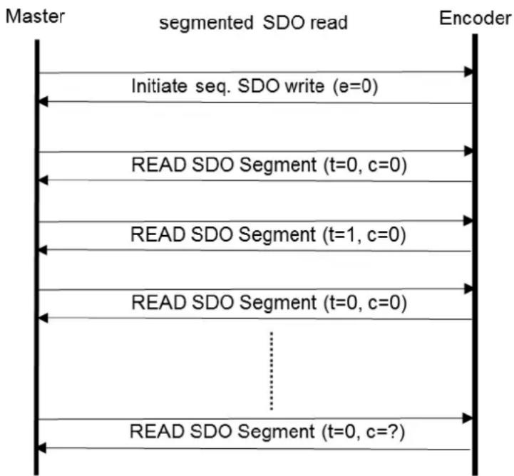
flowchart
graph TD
    A["Master"] --> B["segmented SDO read"]
    B --> C["Encoder"]
    D["Initiate seq. SDO write (e=0)"] --> B
    E["READ SDO Segment (t=0, c=0)"] --> B
    F["READ SDO Segment (t=1, c=0)"] --> B
    G["READ SDO Segment (t=0, c=0)"] --> B
    H["READ SDO Segment (t=0, c=?) "] --> B
Figure 8.3: Segmented SDO read access
In the following example the 8byte "High Precision Position Value" (object 6008h) is read:
| 600h+ID | 8 | 40h01000000bccs=2,e=0,s=0 | 08h | 06h | 00h | 00h | 00h | 00h | 00h |
| CAN-ID | DLC | Command | ObjectL | ObjectH | Sub-Index | Byte0 | Byte1 | Byte2 | Byte3 |
Table 8.17: SDO read request on object 6008h
Initializing segmented read access:

flowchart
graph LR
    A["Master"] -->|request| B["Initiate SDO read"]
    B -->|0| C["Encoder"]
    C -->|indication| D["response"]
    A -->|confirm| E["0"]
    E --> F["7 .. 5 scs = 2"]
    F --> G["4 .. 0 X"]
    G --> H["m"]
    H --> I["reserved"]
    I --> C
    E -->|0| J["7 .. 5 scs = 2"]
    J --> K["4 X"]
    K --> L["3 .. 2 n"]
    L --> M["1 e"]
    M --> N["0 s"]
    N --> O["m"]
    O --> P["d"]
    P --> C
Figure 8.4: Initiate SDO read
| ccs | client command specifier | 2 = initiate read (upload) request |
| scs | server command specifier | 2 = initiate read (upload) response |
| n | Indicates that bytes [8-n,7] don't contain segmented data | Only valid if e=1 and s=1, otherwise 0. |
| e | Transfer type | 0 = segmented transfer1 = expedited transfer |
| s | size indicator | 0 = data set size not indicated1 = data set size indicated |
| m | multiplexor | index/sub index of data to be transferred |
| d | data | e=0, s=0 -> d is reserved.e=0, s=1 -> d = number of bytes to be read.e=1, s=1 -> d = data of length 4-n to be read.e=1, s=0 -> d = unspecified number of bytes to be read. |
| X | not used | always 0 |
| reserved | reserved for further use, always 0 |
Table 8.18: Declaration of used abbreviations in Figure 8.4
The encoders confirms a segmented SDO transfer of 8 bytes data:
| 580h+ID | 8 | 41h01000001bscs=2,e=0,s=1 | 08h | 06h | 00h | 08h | 00h | 00h | 00h |
| CAN-ID | DLC | Command | ObjectL | ObjectH | Sub-Index | Byte0 | Byte1 | Byte2 | Byte3 |
Table 8.19: Confirm SDO read access of object 6008h
Read SDO segment:

flowchart
graph LR
    A["request"] --> B["0"]
    B --> C["7..5 cos=3"]
    C --> D["4 t"]
    D --> E["3..0 X"]
    E --> F["reserved"]
    G["confirm"] --> H["0"]
    H --> I["7..5 scs=0"]
    I --> J["4 t"]
    J --> K["3..1 n"]
    K --> L["0 c"]
    L --> M["seg-data"]
    N["indication"] --> O["8"]
    P回答 "response" --> Q["8"]
    R["master"] --> S["read SDO segment"]
    T["Encoder"] --> U["8"]
Figure 8.5: read SDO segment
| ccs | client command specifier | 3 = read (upload) segment request |
| scs | server command specifier | 0 = read (upload) segment response |
| t | toggle bit | Must alternate for each subsequent segment with t=0 for the first segment. Equal for each pair of request and response. |
| c | more segments indicator | 0 = more segments to be read (uploaded).1 = no more segments to be read (uploaded). |
| seg-data | Segment data | At most 7 byte of segment data. |
| n | Number of bytes that don't contain segment data | Bytes [8-n;7] don't contain segmentn = 0 if no segment size indicated |
| x | not used | always 0 |
| reserved | reserved for further use, always 0 |
Table 8.20: Declaration of used abbreviations in Figure 8.5
Then the first segment is requested:
| 600h+ID | 8 | 60h01100000bccs=3, t=0 | 00h | 00h | 00h | 08h | 00h | 00h | 00h |
| CAN-ID | DLC | Command | ObjectL | ObjectH | Sub-Index | Byte0 | Byte1 | Byte2 | Byte3 |
Table 8.21: read of first segment
The encoder answers with the first data segment:
| 580h+ID | 8 | 00h00000000bscs=0, t=0,n=0, c=0 | data | data | data | data | data | data | data |
| CAN-ID | DLC | Command | ObjectL | ObjectH | Sub-Index | Byte0 | Byte1 | Byte2 | Byte3 |
Table 8.22: answer with first segment
Then the next segment is requested:
| 600h+ID | 8 | 70h01110000bccs=3, t=1 | 00h | 00h | 00h | 08h | 00h | 00h | 00h |
| CAN-ID | DLC | Command | ObjectL | ObjectH | Sub-Index | Byte0 | Byte1 | Byte2 | Byte3 |
Table 8.23: Request next segment
The encoder answers with the next data segment:
| 580h+ID | 8 | 1Dh00011101bscs=0, t=1, n=6, c=1 | data | x | x | x | x | x | x |
| CAN-ID | DLC | Command | Object L | Object H | Sub-Index | Byte0 | Byte1 | Byte2 | Byte3 |
Table 8.24: Answer with next segment
Within this segment the encoder indicates that this was the last data segment and that only the first data byte contained valid data. The 7 data bytes of the first segment and the single valid data byte of the data bytes represent the 8 byte "High Precision Position value" (object 6008h).
Segmented write access on an object:

flowchart
graph TD
    A["Master"] --> B["segmented SDO write"]
    B --> C["Encoder"]
    D["Initiate seq. SDO write (e=0)"] --> B
    E["Write SDO Segment (t=0, c=0)"] --> B
    F["Write SDO Segment (t=1, c=0)"] --> B
    G["Write SDO Segment (t=0, c=0)"] --> B
    H["..."] --> G
    I["Write SDO Segment (t=0, c=?)"] --> B
Figure 8.6: Segmented-SDO write access
The next example shows how to use segmented SDO to write an 8 byte value into the "High precision preset value" (object 6009h). This preset value will set the corresponding "High Precision Position value" (6008h) to the designated value:
SDO write request for 8 bytes of data on object 6009h:
| 600h+ID | 8 | 21h00100001bccs=1,e=0,s=1 | 09h | 06h | 00h | 08h | 00h | 00h | 00h |
| CAN-ID | DLC | Command | ObjectL | ObjectH | Sub-Index | Byte0 | Byte1 | Byte2 | Byte3 |
Table 8.25: SDO write access of object 6009h
The encoder confirms the segmented SDO transfer and requests the first segment:
| 580h+ID | 8 | 60h01100000bscs=3 | 09h | 06h | 00h | 00h | 00h | 00h | 00h |
| CAN-ID | DLC | Command | ObjectL | ObjectH | Sub-Index | Byte0 | Byte1 | Byte2 | Byte3 |
Table 8.26: Acknowledgement of write access of object 6009h
Initializing segmented write access:

flowchart
graph LR
    A["request"] --> B["0"]
    B --> C["7..5 cos=1"]
    C --> D["4 X"]
    D --> E["3..2 n"]
    E --> F["1 e"]
    F --> G["0 s"]
    G --> H["m"]
    H --> I["d"]
    I --> J["Encoder"]
    K["confirm"] --> L["0"]
    L --> M["7..5 scs=3"]
    M --> N["4..0 X"]
    N --> O["m"]
    O --> P["reserved"]
    P --> Q["8"]
    Q --> R["indication"]
    S["response"] --> T["0"]
    T --> U["1"]
    U --> V["4"]
    V --> W["8"]
Figure 8.7: Initiate SDO write
| ccs | client command specifier | 1 = initiate write (download) request |
| scs | server command specifier | 3 = initiate write (download) response |
| n | Indicates that bytes [8-n,7] don't contain segmented data | Only valid if e=1 and s=1, otherwise 0. |
| e | Transfer type | 0 = segmented transfer1 = expedited transfer |
| s | size indicator | 0 = data set size not indicated1 = data set size indicated |
| m | multiplexor | index/sub index of data to be transferred |
| d | data | e=0, s=0 -> d is reserved.e=0, s=1 -> d = number of bytes to be written.e=1, s=1 -> d = data of length 4-n to be written.e=1, s=0 -> d = unspecified number of bytes to be written. |
| X | not used | always 0 |
| reserved | reserved for further use, always 0 |
Table 8.27: Declaration of used abbreviations in Figure 8.7
Then the first data segment is send:
| 600h+ID | 8 | 00h00000000bccs=0, t=0,n=0, c=0 | data | data | data | data | data | data | data |
| CAN-ID | DLC | Command | ObjectL | ObjectH | Sub-Index | Byte0 | Byte1 | Byte2 | Byte3 |
Table 8.28: send first segment
The encoder confirms and requests the next segment:
| 580h+ID | 8 | 20h00100000bscs=1, t=0 | data | data | data | data | data | data | data |
| CAN-ID | DLC | Command | ObjectL | ObjectH | Sub-Index | Byte0 | Byte1 | Byte2 | Byte3 |
Table 8.29: Acknowledgement send by the encoder
Write SDO segment:
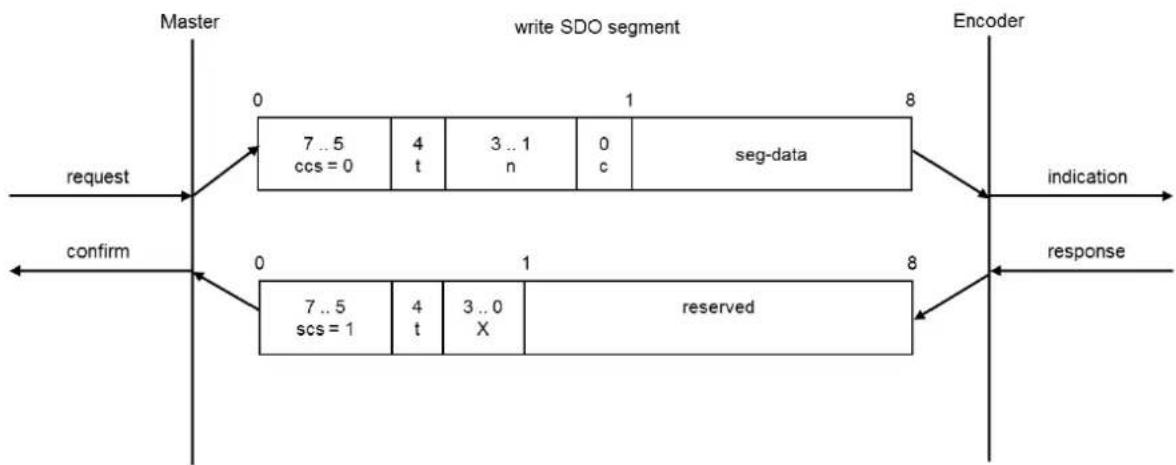
flowchart
graph LR
    A["request"] --> B["0"]
    B --> C["7..5 ccs = 0"]
    C --> D["4 t"]
    D --> E["3..1 n"]
    E --> F["0 c"]
    F --> G["seg-data"]
    H["confirm"] --> I["0"]
    I --> J["7..5 scs = 1"]
    J --> K["4 t"]
    K --> L["3..0 X"]
    L --> M["reserved"]
    N["indication"] --> O["8"]
    P["response"] --> Q["8"]
    R["Encoder"] --> S["8"]
Figure 8.8: write SDO segment
| ccs | client command specifier | 0 = write (download) segment request |
| scs | server command specifier | 0 = write (download) segment response |
| t | toggle bit | Must alternate for each subsequent segment with t=0 for the first segment. Equal for each pair of request and response. |
| c | more segments indicator | 0 = more segments to be written (downloaded).1 = no more segments to be written (downloaded). |
| seg-data | Segment data | At most 7 byte of segment data. |
| n | Number of bytes that don't contain segment data | Bytes [8-n;7] don't contain segmentn = 0 if no segment size indicated |
| x | not used | always 0 |
| reserved | reserved for further use, always 0 |
Table 8.30: Declaration of used abbreviations in Figure 8.8
Now the next data segment can be send:
| 600h+ID | 8 | 1Dh00011101bccs=0, t=1, n=6, c=1 | data | x | x | x | x | x | x |
| CAN-ID | DLC | Command | Object L | Object H | Sub-Index | Byte0 | Byte1 | Byte2 | Byte3 |
Table 8.31: send next segment
Within this segment it is indicated that this was the last data segment and that only the first data byte contained valid data.
The encoder confirms:
| 580h+ID | 8 | 20h00100000bscs=1, t=1 | data | x | x | x | x | x | x |
| CAN-ID | DLC | Command | ObjectL | ObjectH | Sub-Index | Byte0 | Byte1 | Byte2 | Byte3 |
Table 8.32: Acknowledgement send by the encoder
The 7 data bytes of the first segment and the single valid data byte of the data bytes represent the 8 byte "High Precision Position Preset Value" (object 6009h).
8.3.3 Baudrate selection
The encoders WDGA by Wachendorff Automation provide an automatic baudrate detection. It is also possible to use a fixed baudrate which can be set by either LSS (as described above) or SDO.
The configuration of the encoder is only possible in Pre-Operational mode. To alter the baudrate you have to change the object 2100h into Sub-Index 00h. This can be achieved with a simple SDO write command with the target baudrate as data.
| 600h+ID | 8 | 2Fh | 00h | 21h | 00h | Baud | 00h | 00h | 00h |
| CAN-ID | DLC | Command | Object L | Object H | Sub-Index | Byte0 | Byte1 | Byte2 | Byte3 |
Table 8.33: SDO command – set baudrate
The following values represent the valid baud rates:
- The new baudrate will become effective after a reset of the encoder (hard reset or NMT reset). Writing on object 2100h is not protected and the change will be immediately stored in the internal EEPROM. It is not necessary to perform a "save parameters".
8.3.4 Node-ID selection
It is possible to change the node ID of the encoder by SDO. To set the node ID the object 2101h, sub-Index 00h, has to be changed (only possible in Pre-Operational state!) with a simple SDO write command:
| 600h+ID | 8 | 2Fh | 01h | 21h | 00h | Node | 00h | 00h | 00h |
| CAN-ID | DLC | Command | Object L | Object H | Sub-Index | Byte0 | Byte1 | Byte2 | Byte3 |
Valid node IDs can be:
| Encoder number (d) | Node-ID (h) |
| 1 | 01h |
| 2 | 02h |
| ... | ... |
| 127 | 7Fh |
Table 8.36: Valid Node-IDs

- The new node ID will become effective after an encoder reset (hard reset or NMT reset). Writing on object 2101h is not protected and the change will be immediately stored in the internal EEPROM. It is not necessary to perform a "save parameters".

- Changing the Node ID automatically adjusts the PDO and EMCY COB-IDs. After the first manual storage, they are set to their current value and will be no longer automatically adjusted. Performing the "Restore Defaults" command will re-enable automatic adjustment.
8.3.5 Basic NMT commands
This subsection describes several basic NMT commands. Basic information are available at 5.4.
To set the encoder into Operational state, the "Start remote node" command is used:
Table 8.37: NMT command - Start remote node
To change the encoder into Stopped state, the "Stop remote node" command is used:
Table 8.38: NMT command - Stop remote node
To switch the encoder into Pre-Operational state, the "Enter Pre-Operational State" command is used:
Table 8.39: NMT command - Enter Pre-Operational-state
A reset of communication with a change into Pre-Operational after re-initialisation will be achieved by:
Table 8.40: NMT command - Reset node communication
To perform a soft reset of the encoder, the "Reset Remote Node" is used. After the reset the encoder will send his boot-up message and enter Pre-Operational by default:
Table 8.41: NMT command - Reset remote node
8.4 Heartbeat settings
To configure and start the producer heartbeat (e.g. heartbeat every 5000 milliseconds; 5000d=1388h) use SDO on object 1017h:
| 600h+ID | 8 | 2Bh | 17h | 10h | 00h | 88h | 13h | 00h | 00h |
| CAN-ID | DLC | Command | Object L | Object H | Sub-Index | Byte0 | Byte1 | Byte2 | Byte3 |
Table 8.42: Example of heartbeat setting
This is the structure of a heartbeat message:
| 700h+ID | 1 | d | NMT-Status |
| CAN-ID | DLC | Data/Remote | Byte 0 |
Table 8.43: Structure of heartbeat message
NMT-state:
| NMT-Status | Code |
| Boot-up | 00h |
| Stopped | 04h |
| Pre-Operational | 7Fh |
| Operational | 05h |
Table 8.44: Heartbeat NMT-state-coding
8.5 PDO Configuration
8.5.1 PDO parameters
Four PDOs can be parameterised. The configuration of the PDO payload is called "PDO mapping". The default configuration is:
| Object | PDO | Default configuration (scheduling) | “Mapped” process data |
| 1800h | PDO1 | asynchronous / on change of position value | Position-value |
| 1801h | PDO2 | synchronous / on every SYNC | Position-value |
| 1802h | PDO3 | synchronous / on every SYNC | High Precision-value |
| 1803h | PDO4 | disabled |
Table 8.45: Default PDO configuration
There are five different types of transmission for every PDO:
| Sub-Index 2 | Sub-Index 5 | Description |
| 01h-F0h | n.n. | PDO synchronous / on a SYNC |
| FFh | 0000h | PDO disabled |
| FEh | 0001h-FFFFh | PDO asynchronous / triggered by event timer AND change in position value |
| FEh | 0000h | PDO asynchronous / triggered by change of position value |
| FFh | 0001h-FFFFh | PDO asynchronous / triggered by event timer |
Table 8.46: Selectable PDO transmission types
 | • Parameters can be changed in Pre-Operational only and have to be saved into EEPROM! |
To completely disable a PDO, you have to change the MSB of the PDO-COBID object:
| PDO | Object | COB-ID object PDO enabled | COB-ID object PDO disabled |
| 1 | 1800h | 4000 0181h | C000 0181h |
| 2 | 1801h | 4000 0281h | C000 0281h |
| 3 | 1802h | 4000 0381h | C000 0381h |
| 4 | 1803h | 4000 0481h | C000 0481h |
Table 8.47: PDO-Deactivation
For example PDO1 shall be disabled by this SDO write command:
| 600h+ID | 8 | 23h | 00h | 18h | 01h | 81h | 01h | 00h | C0h |
| CAN-ID | DLC | Command | Object L | Object H | Sub-Index | Byte0 | Byte1 | Byte2 | Byte3 |
Table 8.48: Example - PDO1 deactivation
 | Advanced parameterisation of the PDO COB-ID (objects 1800h-01h, objects 1801h-01h, objects 1802h-01h, objects 1803h-01h) is possible. As long as no "save communication objects" or "save all parameters" has been performed, a change of the node ID will automatically effect the COB IDs.After a save command, the PDO COB-IDs have to be changed manually or perform a "restore all parameters". |
8.5.2 Synchronous PDO
A PDO can be configured for synchronous transmission, i.e. to respond on a SYNC message. The sub index 2 of the transmission type parameter determines after which number of SYNCs received the PDO will be transmitted. (e.g.: If set to 05h, the device transmits only on every 5. SYNC). Here PDO1 is configured 01h in 1800h-02h:
| 600h+ID | 8 | 2Fh | 00h | 18h | 02h | 01h | 00h | 00h | 00h |
| CAN-ID | DLC | Command | Object L | Object H | Sub-Index | Byte0 | Byte1 | Byte2 | Byte3 |
Table 8.49: Parametrization of PDO1 Sub-Index 2
Therefore transmission type for PDO1 is now synchronous. In Operational state the PDO1 will be sent as a response on every SYNC message received.
8.5.3 Asynchronous PDO
Cyclic (triggered by internal event timer):
PDOs can be configured for asynchronous cyclic transmission.
Therefor the transmission type in object 1800h-02h (respectively 1801h-02h, 1802h-02h, 1803h-02h) has to be set to FFh. Sub index 5 of the same object is the cycle time in milliseconds.
Example: PDO1 transmitting asynchronously cyclic:
| 600h+ID | 8 | 2Fh | 00h | 18h | 02h | FFh | 00h | 00h | 00h |
| CAN-ID | DLC | Command | Object L | Object H | Sub-Index | Byte0 | Byte1 | Byte2 | Byte3 |
Table 8.50: Parametrization of PDO1 Sub-Index 2
Example: PDO1 with a cycle time of 30 milliseconds (1Eh):
| 600h+ID | 8 | 2Bh | 00h | 18h | 05h | 1Eh | 00h | 00h | 00h |
| CAN-ID | DLC | Command | Object L | Object H | Sub-Index | Byte0 | Byte1 | Byte2 | Byte3 |
Table 8.51: Parametrization of PDO1 Sub-Index 5 to 30ms
PDO1 is now in asynchronous mode and will be sent every 30 milliseconds when the encoder is in Operational state.
Triggered by a manufacturer specific event (change of position value):
To use this transmission type, sub-index 2 has to be FEh and the event timer in sub-index 5 has to be disabled (00h), e.g.:
| 600h+ID | 8 | 2Fh | 00h | 18h | 02h | FEh | 00h | 00h | 00h |
| CAN-ID | DLC | Command | Object L | Object H | Sub-Index | Byte0 | Byte1 | Byte2 | Byte3 |
Table 8.52: Parametrization of PDO1 Sub-Index 2
| 600h+ID | 8 | 2Bh | 00h | 18h | 05h | 00h | 00h | 00h | 00h |
| CAN-ID | DLC | Command | Object L | Object H | Sub-Index | Byte0 | Byte1 | Byte2 | Byte3 |
Table 8.53: Parametrization of PDO1 Sub-Index 5
After resetting, the encoder's PDO1 will be in asynchronous mode and be sent out if the measuring value changes.

- The use of this setting may cause heavy bus load. Therefore we recommend the use of synchronous or timer triggered transmission.
8.5.4 Variable PDO-mapping
Variable PDO-mapping means that the PDO payload can be configured by the user. This mapping must match between encoder and receiver. The maximum payload for a PDO is 8 bytes. The mapping is also limited by the size of the objects to be mapped. E.g. you can map the "position value" (4 bytes), the "speed value" (2 bytes) and the "acceleration" value (2 bytes) into the same object. Due to the fixed size of a CAN frame this produces less bus load than transmitting the three objects by 3 individual PDOs. This table shows a possible PDO mapping:
| Object no | Sub-Index | Datatype | Size | Description |
| 6004h | 00h | Unsigned32 | 4 Byte | Position value |
| 6030h | 01h | Integer16 | 2 Byte | Speed value |
| 6040h | 01h | Integer16 | 2 Byte | Acceleration value |
Table 8.54: Example of a mapping-table
The data 1, 2 und 3 (see mapping, Table 8.54) are spread over the PDOs 8 payload bytes. The current payload is 4byte + 2 byte + 2byte = 8 byte. So the PDO is used with 100% efficiency!
The resulting PDO has this structure:
PDO1:
1a, 1b, 1c, 1d = 4 bytes of information 1; 2a, 2b = 2 bytes of information 2; 3a, 3b = 2 bytes der information 3.

- To use the WDGA PDO mapping the mapping parameters for the transmit PDO have to be configured (see object dictionary, Table 6.1 ff.).
- Step 1: Delete current mapping
- Step 2: Re-mapping the PDO
- Step 3: Activating the new mapping
For example to change the PDO1 mapping you have to access the PDO1 mapping parameter object 1A00h.
Step 1: Delete current mapping
First the sub-index 0 of the Mapping parameter object has to be set to zero:
| 600h+ID | 8 | 2Fh | 00h | 1Ah | 00h | 00h | 00h | 00h | 00h |
| CAN-ID | DLC | Command | Object L | Object H | Sub-Index | Byte0 | Byte1 | Byte2 | Byte3 |
Table 8.56: Mapping parameter
The encoder is now ready for remapping.
Step 2: Re-mapping the PDO
Mapping of the position value: (No.:1 (Size 32 bit = 20h) into object 1A00h sub-index 1 for PDO1):
| 600h+ID | 8 | 23h | 00h | 1Ah | 01h | 20h | 00h | 04h | 60h |
| CAN-ID | DLC | Command | Object L | Object H | Sub-Index | Byte0 | Byte1 | Byte2 | Byte3 |
Table 8.57: Mapping position value
The SDO command contains the object to be mapped and its size (object 6004h, sub-index 0, Size 20h = 4 Byte).
Mapping of speed value (No.:2 (Size 16 bit = 10h) into object 1A00h sub-index 2 for PDO1):
| 600h+ID | 8 | 23h | 00h | 1Ah | 02h | 10h | 01h | 30h | 60h |
| CAN-ID | DLC | Command | Object L | Object H | Sub-Index | Byte0 | Byte1 | Byte2 | Byte3 |
Table 8.58: Mapping speed value
The SDO command contains the object to be mapped and its size: (Object 6030h, sub-index 1, Size 10h = 2 Byte).
Mapping of acceleration value (No.:3 (Size 16 bit = 10h) into object 1A00h sub-index 3 for PDO1):
| 600h+ID | 8 | 23h | 00h | 1Ah | 03h | 10h | 01h | 40h | 60h |
| CAN-ID | DLC | Command | Object L | Object H | Sub-Index | Byte0 | Byte1 | Byte2 | Byte3 |
Table 8.59: Mapping acceleration value
The SDO command contains the object to be mapped and its size: (Object 6040h, sub-index 1, Size 10h = 2 Byte).
Step 3: Activating the new mapping
To activate the new mapping, the new number of mapped objects must be written into sub-index 0 of the mapping parameter object. In our example three objects are mapped, therefore sub-index 0 has to be set to 03h.:
| 600h+ID | 8 | 2Fh | 00h | 1Ah | 00h | 03h | 00h | 00h | 00h |
| CAN-ID | DLC | Command | Object L | Object H | Sub-Index | Byte0 | Byte1 | Byte2 | Byte3 |
Table 8.60: Mapping parameter – activate new mapping
The re-mapping of PDO1 is now completed and valid, but it should be saved into the EEPROM (see 8.12).
8.6 Changing resolution and direction

- To change resolution and direction of the encoder the scaling option has to be activated.
- While activating the scaling you can change the counting direction (clockwise (CW) or counter-clockwise (CCW) in one step (default setting is CW)).
- The counting direction is referred to the movement of the axis when looking onto the flange side of the encoder.
The object for this configuration is 6000h sub-index 00h. Here is the list of possible settings:
| Code Byte 0 | Scaling | Direction |
| 00h | OFF | Clockwise (CW) |
| 01h | OFF | Counter-clockwise (CCW) |
| 04h (default) | ON | Clockwise (CW) |
| 05h | ON | Counter-clockwise (CCW) |
Table 8.61: Counting direction and scaling parameters
This is an example how to set the "operating parameters" object 6000h to "scaling ON" and "CCW":
| 600h+ID | 8 | 2Bh | 00h | 60h | 00h | 05h | 00h | 00h | 00h |
| CAN-ID | DLC | Command | Object L | Object H | Sub-Index | Byte0 | Byte1 | Byte2 | Byte3 |
Table 8.62: Example setting operating parameters
The encoder responds with a standard SDO acknowledge. Now scaling is active and the two scaling parameters "measuring range per revolution" and "total measuring range" are applied. Singleturn resolution and total measuring range can now be changed.
- The measuring range per revolution or singleturn resolution is the number of units (bit) per revolution.
- The total measuring range is the singleturn resolution multiplied with the number of countable revolutions (multiturn resolution).
Example: Singleturn resolution: 4096 steps per revolution = 12 bit = 10 00h Total measuring range: 536 870 912 units = 29 bit = 20 00 00 00h) => Max. Multiturn resolution: 29 Bit - 12 Bit = 17 Bit = 131072 revolutions (02 00 00h)
The singleturn resolution is editable in object 6001h:
| 600h+ID | 8 | 23h | 01h | 60h | 00h | 00h | 10h | 00h | 00h |
| CAN-ID | DLC | Command | Object L | Object H | Sub-Index | Byte0 | Byte1 | Byte2 | Byte3 |
Table 8.63: Change of singleturn-resolution by SDO
00 00 10 00h represent the designated singleturn resolution. The encoder responds with a SDO acknowledge.
The total measuring range can be changed similarly by object 6002h. In the example a 29 bit total measuring range is selected. With a 12 bit singleturn resolution 17 bit rotations are counted before returning to zero:
| 600h+ID | 8 | 23h | 02h | 60h | 00h | 00h | 00h | 00h | 20h |
| CAN-ID | DLC | Command | Object L | Object H | Sub-Index | Byte0 | Byte1 | Byte2 | Byte3 |
Table 8.64: Change of total measuring range by SDO
20 00 00 00h is the designated total measuring range.
Singleton resolution and total measuring range do not have to match the bit grid. Every value between 1 and the maximum is valid. The total measuring range cannot be less than the singleturn resolution. The result of an invalid setting will be an abort code.

- From revision number (software version) 1.12, it is no longer possible to scale object 6004 to 32 bits. Only devices, ordered as a 32-bit device (default resolution = 32-bit) provide full 32-bit resolution. Object 6002 has a "0". For all other variants, only a scaling to 232 - 1 is possible.
8.7 Position preset
With object 6003h the encoder position can be shifted to a preset value. E.g. you can set the zero position of your application without time-consuming mechanical alignment. Just mount the encoder and set the preset object 6003h to the designated position value (p1-p4):
| 600h+ID | 8 | 23h | 03h | 60h | 00h | p1 | p2 | p3 | p4 |
| CAN-ID | DLC | Command | Object L | Object H | Sub-Index | Byte0 | Byte1 | Byte2 | Byte3 |
Table 8.65: Set position preset

- To set the zero position: p1, p2, p3, p4 = 00h, 00h, 00h, 00h
You don't have to use PDOs to check the current position value. You can also perform a SDO read access on the position value object 6004h:
| 600h+ID | 8 | 40h | 04h | 60h | 00h | 00h | 00h | 00h | 00h |
| CAN-ID | DLC | Command | Object L | Object H | Sub-Index | Byte0 | Byte1 | Byte2 | Byte3 |
Table 8.66: Check current position
The encoder will respond with the current position value.
8.8 Position value filtering
The encoder provides an internal filtering for the position value. Sub-index 1 of object 2105h is the filter parameter for the internal "IIF"-filter (infinite impulse response filter). 01h for the filter parameter deactivates the filter. The maximum value is 04h. A filtered position value is more stable at the cost of less dynamic.
8.9 Change speed-integration and speed scaling
The encoder uses an "integration time" to calculate the speed value. This time interval can be adjusted by object 2105h, sub-Index 2. The unit for this time is milliseconds. The default value of 1000 milliseconds is suitable for most applications.
The change of the integration time will result in a more or less dynamic behaviour of the speed value, similar (but independent) to the filtering of the position value.
The speed scaling can be edited by object 2106h. The Sub-Indices 1 (= numerator) and 2 (= denominator) form a scaling factor (here: "z") for the speed scaling. Default value is "1". The speed value is always given in Increments per second.
Object 2106h is a signed16 value with the limits of ±32767 representing ±120 revolutions per minute.
For example the speed shall be scaled to a maximum of ±2500 rpm:
z = Skaling factor z = kn 1
n = Max revolutions per minute z = 1 2 02 5 0 0 2
k = Calculation factor = 1 2 0 z = 61 2 5 3
So object 2106h-01h must be set to 6d = 06h and 2106h-02h set to 125d=7Dh, so the limits of ±32767 are scaled to ±2500 U/min.
Applying this scaling, the limits ±32767 corresponds with ±2500 rpm.
8.10 Frequency limit
If the speed value exceeds the frequency limit 2107h a warning flag is set (no EMCY). The valid area is 1 to 65535 representing the maximum allowed rotation speed (e.g. 2520 rpm = 42 rotations per second = 002Ah as frequency limit).
8.11 CAM-configuration
This section gives an example how to configure the cam-channel:
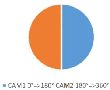
pie
| Category | Value (%) | |---|---| | CAM1 0°=>180° | Orange | | CAM2 180°=>360° | Blue |
pie
| Category | Value | |---|---| | CAM3 0°=>60° | 0 | | Other | 1 |That means for single cams:
| CAM | Angular area | lower CAM-limit | upper CAM-limit | Hysteresis |
| 1 | 0°..180° | 0 | 2048 | 0 |
| 2 | 180°..360° | 2049 | 4095 | 0 |
| 3 | 0°..60° | 0 | 682 | 0 |
Table 8.67: Example CAM-configuration

- The configuration must be done in Pre-Operational state.
To enable the individual cams the CAM-enable-register (object 6301h-01h) is used. For example the setting 00000111b = 07h enables the first three cams.
| 600h+ID | 8 | 23h | 01h | 63h | 01h | 07h | 00h | 00h | 00h |
| CAN-ID | DLC | Command | Object L | Object H | Sub-Index | Byte0 | Byte1 | Byte2 | Byte3 |
Table 8.68: Enable first three cams
Now the cam-high-limits 1, 2, and 3 can be set as in the table above:
CAM 1 = 2 0 4 8 = 0 8 0 0 h
| 600h+ID | 8 | 23h | 20h | 63h | 01h | 00h | 08h | 00h | 00h |
| CAN-ID | DLC | Command | Object L | Object H | Sub-Index | Byte0 | Byte1 | Byte2 | Byte3 |
Table 8.69: CAM-High-Limit 1
CAM 2 = 4 0 9 5 = 0 FFFh
| 600h+ID | 8 | 23h | 21h | 63h | 01h | FFh | 0Fh | 00h | 00h |
| CAN-ID | DLC | Command | Object L | Object H | Sub-Index | Byte0 | Byte1 | Byte2 | Byte3 |
Table 8.70: CAM-High-Limit 2
CAM 3 = 6 8 2 = 0 2 AAh
| 600h+ID | 8 | 23h | 23h | 63h | 01h | AAh | 02h | 00h | 00h |
| CAN-ID | DLC | Command | Object L | Object H | Sub-Index | Byte0 | Byte1 | Byte2 | Byte3 |
Table 8.71: CAM-High-Limit 3
The setting of the CAM-Low-Limits 1, 2 and 3 is similar:
CAM 1 = 0 = 0 0 h
| 600h+ID | 8 | 23h | 10h | 63h | 01h | 00h | 00h | 00h | 00h |
| CAN-ID | DLC | Command | Object L | Object H | Sub-Index | Byte0 | Byte1 | Byte2 | Byte3 |
Table 8.72: CAM-Low-Limit 1
CAM 2 = 2 0 4 9 = 0 8 0 1 h
| 600h+ID | 8 | 23h | 11h | 63h | 01h | 01h | 08h | 00h | 00h |
| CAN-ID | DLC | Command | Object L | Object H | Sub-Index | Byte0 | Byte1 | Byte2 | Byte3 |
Table 8.73: CAM-Low-Limit 2
CAM 3 = 0 = 0 0 h
| 600h+ID | 8 | 23h | 12h | 63h | 01h | 00h | 00h | 00h | 00h |
| CAN-ID | DLC | Command | Object L | Object H | Sub-Index | Byte0 | Byte1 | Byte2 | Byte3 |
Table 8.74: CAM-Low-Limit 3
In our example the CAM-Hysteresis shall be 0, so there is no change necessary.
With the CAM-Polarity-Register the polarity of the cams can be inverted.
Using object 6300h Sub-Index 1 the CAM-state-register can be read. The CAM-state-register is also PDO mappable! For more details see 7.5.1 CAM-state-register. To save the configuration into the EEPROM, see 8.12.1 "Saving parameters into EEPROM".
8.12 Non-volatilylly storage of parameters
8.12.1 Saving parameters into EEPROM
Non-volatile storage of parameters using object 1010h:
| Sub-Index | Access mode | Description |
| 0 | co | Number of objects |
| 1 | wo | Save all parameters |
| 2 | wo | Save communication objects |
| 3 | wo | Save application objects |
| 4 | wo | Save manufacturer objects |
Table 8.75: Saving parameters

- To trigger the storage operation the "ASCII" value for "save" (in hex: 65766173h) has to be written into the dedicated sub-index.
E.g. "Save all Parameters":
| 600h+ID | 8 | 23h | 10h | 10h | 01h | 73h | 61h | 76h | 65h |
| CAN-ID | DLC | Command | Object L | Object H | Sub-Index | Byte0 | Byte1 | Byte2 | Byte3 |
Table 8.76: Example – Save all parameters
8.12.2 Restoring default parameters from EEPROM
Restoring default settings by using object 1011h:
| Sub-Index | Access mode | Description |
| 0 | co | Number of objects |
| 1 | wo | Restore all parameters |
| 2 | wo | Restore communication objects |
| 3 | wo | Restore application objects |
| 4 | wo | Restore manufacturer objects |
Table 8.77: Restoring parameters

- To restore the default settings the "ASCII" value "load" (in hex: 64616F6Ch) has to be written to the dedicated sub-index of the object.
- Attention: The baudrate and node-ID settings, as well as the customer data object, will not be restored!
9 Error diagnosis
9.1 Encoder configurations
| Error description | Check |
| Encoder doesn’t work, the LED stays dark. | Check connections, power supply and pin assignment. |
| Encoder is connected correctly, but doesn’t work. | Use a CAN monitoring tool to check if the encoder sends its boot-up message when started. |
| No communication with the encoder. | Check node ID and baudrate. |
| Status LED is shining orange, no communication. | Check the correct termination (2 terminations, 120 Ohms each, at the ends), and the length of the bus lines and stub cables. |
| The bus load exceeds 85%. | Too many error messages on the bus. Check terminations and length of stubs. |
| After connection the encoder goes bus-passive or bus-off immediately. | Check baudrate and node IDs of all nodes, if connected. |
| There are irregular failures during transmission. | Encoder is stuck in its initiation due to a hardware failure. Please contact our technical support. |
Table 9.1: Error diagnosis – Encoder configuration
10 Support
Technical application advisor
Do you have any questions about this product?
Our technical application advisor will be pleased to help you.
Tel.: +49 (0) 67 22 / 99 65 414
E-Mail: support-wa@wachendorff.de
Notes:


- Technical Manual
- Absolute Encoders WDGA
- with CANopen interface
- Imprint
- Guarantee waiver, right of amendment, copyright protection:
- Comments:
- Introduction .... 1
- Safety information....3
- Device description....5
- Quick start....8
- General information about CAN 11
- WDGA object dictionary....19
- Object description 30
- Setting-up the encoder....39
- Error diagnosis....70
- Support....71
- Index of figures
- Index of tables
- Introduction
- Encoder types
- WDGA CANopen
- About this manual
- Symbols
- Specifications
- Safety information
- General safety information
- Intended use
- Safe working
- Disposal
- Device description
- Basic encoder design
- Predefined Connection Settings
- LED status indicator and signal codes
- Definition of LED indication types:
- Green ON
- Green blinking
- Green
- Red ON
- Red single flash
- Quick start
- CAN network integration
- SDO command to set the node ID
- Setting-up the encoder
- General information about CAN
- CAN physical and transport layer
- CANopen
- Specifications and profiles
- Overview
- Mechanisms of communication
- SDO Service Data Object
- PDO Process Data Object
- Object dictionary
- Network management (NMT)
- Description of the NMT-states:
- Heartbeat and Node-Guarding
- Emergency messages
- WDGA object dictionary
- Communication objects
- Device specific objects
- Manufacturer specific objects
- Object description
- Network management (NMT) commands
- Command:
- Node-ID:
- Heartbeat protocol
- Emergency messages (EMCY)
- Error register:
- List info field:
- Error Objects
- Manufacturer status register
- Alarms
- Warnings
- Electronic cam switch (CAM)
- CAM-state-register
- CAM-enable-register
- CAM-polarity-register
- CAM-Low-Limit
- CAM-High-Limit
- CAM-Hysteresis
- Device profile
- SYNC
- Encoder designation
- Error behaviour
- NMT start-up behaviour
- Bus-Off Auto-Reset
- Customer Data
- Temperature
- Verify Configuration
- Setting-up the encoder
- Mechanical and electrical connection
- Pin assignment (according to CiA 303):
- Configuration via LSS
- General settings
- For the CAN-ID applies:
- LSS configuration by "Switch Mode Global"
- LSS configuration by "Switch Mode Selective"
- End LSS configuration mode
- Error Code:
- Specific Error:
- Configuration via SDO
- SDO access on objects
- SDO access on objects larger than 4 bytes
- Segmented read access on an object:
- Initializing segmented read access:
- Read SDO segment:
- Then the first segment is requested:
- The encoder answers with the first data segment:
- Segmented write access on an object:
- Write SDO segment:
- Baudrate selection
- Node-ID selection
- Basic NMT commands
- Heartbeat settings
- PDO Configuration
- PDO parameters
- Synchronous PDO
- Asynchronous PDO
- Cyclic (triggered by internal event timer):
- Triggered by a manufacturer specific event (change of position value):
- Variable PDO-mapping
- Step 1: Delete current mapping
- Step 2: Re-mapping the PDO
- Step 3: Activating the new mapping
- Changing resolution and direction
- Position preset
- Position value filtering
- Change speed-integration and speed scaling
- Frequency limit
- CAM-configuration
- Non-volatilylly storage of parameters
- Saving parameters into EEPROM
- Restoring default parameters from EEPROM
- Error diagnosis
- Encoder configurations
- Support
- Technical application advisor
Brand : Wachendorff
Model : WDGA 36C
Category : Industrial sensor