
WDGA 58E - Industrial sensor Wachendorff - Free user manual and instructions
Find the device manual for free WDGA 58E Wachendorff in PDF.


| Product Type | Absolute Rotary Encoder with PROFIBUS-DP Interface |
| Model Series | WDGA 58E |
| Flange Diameter | 58 mm |
| Shaft Type | End Hollow Shaft |
| Measuring Principle | Singleturn (ST) and Multiturn (MT) with EnDra® technology (maintenance-free, battery-free) |
| Interface | PROFIBUS-DP (DP-V0, DP-V1, DP-V2) |
| Supply Voltage | +UB (typically 10–30 V DC, see label) |
| Power Consumption | Approximately 2–3 W (typical) |
| Resolution (Singleturn) | Up to 14 bits (physical), programmable via scaling |
| Resolution (Multiturn) | Up to 39 bits (physical), programmable via scaling |
| Position Update Rate | Cyclic data exchange, configurable telegram (81–84, 59000) |
| Speed Output | 16-bit or 32-bit speed value (NIST_A or NIST_B) |
| Preset Function | Absolute and relative preset via control word |
| Scaling | Programmable measuring units per revolution and total measuring range |
| Diagnostics | LED signaling (BUS and DEV), extended diagnosis via DP-V1, alarm channel |
| Bus Cover Options | BP1 (PG screw), BP2 (M12), DB4 (2x M12, 1x M8), SD9/SE9 (D-Sub) |
| Ambient Temperature | –20 °C to +85 °C (estimation, refer to datasheet) |
| Ingress Protection | Typically IP67 (depending on variant and connection) |
| Weight | Approximately 300 g (typical for 58 mm encoder) |
| Maintenance | Maintenance-free (EnDra® multiturn technology) |
| Safety | Installation by qualified electrician; observe EMC and machine directives |
| Spare Parts / Accessories | Connectors, termination resistors, PG glands, M12 cables, spring plates (see website) |
| Manufacturer | Wachendorff Automation GmbH & Co. KG |
Frequently Asked Questions - WDGA 58E Wachendorff
User questions about WDGA 58E Wachendorff
0 question about this device. Answer the ones you know or ask your own.
Ask a new question about this device
Download the instructions for your Industrial sensor in PDF format for free! Find your manual WDGA 58E - Wachendorff and take your electronic device back in hand. On this page are published all the documents necessary for the use of your device. WDGA 58E by Wachendorff.
USER MANUAL WDGA 58E Wachendorff
natural_image
Infographic with eight white hexagonal icons representing industrial and renewable energy sectors (no text or symbols)Technical Manual
Absolute Encoders WDGA
with PROFIBUS interface
wachendorff-automation.com
PROFI
BUS
EnDra®
Technologie
Impressum

natural_image
Close-up of two electronic devices showing internal components with no visible text or symbols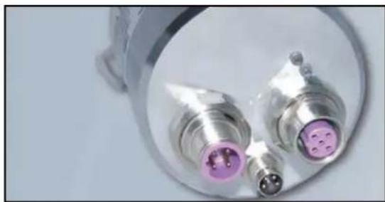
natural_image
Close-up of two metallic electronic components with purple connectors and a pink connector, mounted on a circular base (no visible text or symbols)Managing Director: Robert Wachendorff
Guarantee waiver, right of amendment, copyright protection:
The company Wachendorff Automation assumes no liability and provides no guarantee for the correctness of this manual's contents or for any resulting direct or indirect damages. In the interests of continuous innovation and cooperation with our customers, we reserve the right to change technical data or content at any time.
The company Wachendorff Automation claims copyright protection for this manual. It may not be modified, extended, reproduced, or forwarded to third parties without our prior written consent.
Comments:
Should you have any suggested corrections, comments or requests for change, we invite you to submit them to us. Please send your comments to: support-wa@wachendorff.de
1 Introduction .... 1
1.1 About this manual.... 1
1.1.1 Symbols 2
1.1.2 You will not find the following in this manual: 2
1.2 Product assignment.... 3
1.3 Specifications 4
1.4 Scope of delivery 4
2 Safety information....5
2.1 General safety information 5
2.2 Intended use....5
2.3 Safe working....6
2.4 Disposal....6
3 Device description....7
3.1 General information....7
3.2 WDGA-Basics 7
3.2.1 Singleturn - ST 8
3.2.2 Multiturn - MT (EnDra®) 8
3.2.3 Direction of rotation....8
3.2.4 Preset 8
3.2.5 Scaling 8
3.3 Default settings.... 10
3.3.1 General information 10
3.3.2 Rotary encoder - with bus cover 10
3.3.3 Rotary encoder - without bus cover 10
3.4 LED signalling.... 11
3.5 BP1 - Bus cover with 3x PG screw connection.... 12
3.6 BP2 - Bus cover with 3x M12 13
3.7 DB4 - without bus cover 2x M12, 1x M8.... 14
3.8 SD9/SE9 - without bus cover, D-Sub 15
3.9 Rotary encoder and bus cover label.... 16
3.10 GSD file.... 17
4 Installation....18
4.1 General information.... 18
4.2 Mechanical connection.... 19
4.2.1 Shaft encoder.... 19
4.2.2 Hollow shaft encoders.... 19
4.3 Shielding.... 20
4.4 Connecting the encoder - with bus cover 21
4.4.1 General information 21
4.4.2 Setting the slave address.... 22
4.4.3 Termination 23
4.4.4 Connecting the signal and supply lines.... 23
4.5 Connecting the encoder - without bus cover 28
4.5.1 Setting the slave address.... 28
4.5.2 Termination 29
4.5.3 Connecting the signal and supply lines.... 30
5 Project planning 32
5.1 General information.... 32
5.2 Installing the GSD file.... 32
5.3 Integration of the WDGA 34
5.3.1 Communicating the slave address 35
5.3.2 Setting I/O addresses 36
5.3.3 Parameterization - Class 4.... 37
5.3.4 Set diagnostic address.... 38
5.4 Creating the Symbol Table 39
5.5 Position & Speed 40
5.6 Set preset value - Class 4 42
5.7 Error management.... 45
5.8 Reading the diagnosis.... 47
5.9 S7 sample program 47
6 Encoders - Class 4 ....48
6.1 General information.... 48
6.2 Configuration 48
6.2.1 Telegram structures 49
6.2.2 Signal list.... 50
6.3 Parameterisation 50
6.3.1 Code sequence.... 51
6.3.2 Class 4 functionality .... 51
6.3.3 G1_XIST1 preset control 52
6.3.4 Scaling function control 52
6.3.5 Alarm channel control 52
6.3.6 Compatibility mode 52
6.3.7 Measuring units per revolution....53
6.3.8 Total measuring range 53
6.3.9 Maximum Master Sign-Of-Life failures 54
6.3.10 Speed measuring unit.... 54
6.4 Exchange of data.... 55
6.4.1 Telegram structure....55
6.4.2 G1_STW 55
6.4.3 G1_ZSW 57
6.4.4 G1_XIST1 58
6.4.5 G1_XIST2 58
6.4.6 G1_XIST3 60
6.4.7 NIST_A & NIST_B 61
6.4.8 Debug_STW & Debug_ZSW 61
6.4.9 STW2_ENC & ZSW2_ENC 61
6.5 Diagnosis.... 63
6.6 I&M functions.... 64
6.6.1 I&M0 64
6.6.2 I&M1 64
6.6.3 I&M2 65
6.6.4 I&M3 65
6.6.5 I&M4 65
6.7 Acyclic parameter access.... 66
6.7.1 Basics 66
6.7.2 Read parameters 69
6.7.3 Write parameters 70
6.7.4 Error handling 71
6.7.5 PROFIdrive parameters 72
6.7.6 Manufacturer specific parameters.... 76
6.7.7 Encoder-specific parameters 77
6.8 Slave cross traffic - DxB 79
6.9 Isochronous mode - IsoM 80
6.9.1 State machine....80
6.9.2 Offline 80
6.9.3 Preparation Phase 1 81
6.9.4 Preparation Phase 2 81
6.9.5 Synchronisation 81
6.9.6 Surgery 82
7 PROFIBUS....83
7.1 General information....83
7.2 Attendee 84
7.3 Physical Layer - Layer 1 85
7.3.1 Bus line 85
7.3.2 Transmission speed....86
7.3.3 Termination 88
7.4 Data Link Layer - Layer 2 89
7.4.1 General information 89
7.4.2 Bus access method.... 89
7.5 Application Layer - Layer 7....90
7.5.1 Communication protocol - DP-V0, DP-V1, DP-V2....90
7.6 Communication relationships 92
7.6.1 MS0 communication relationship 93
7.6.2 MS1 communication relationship 93
7.6.3 MS2 communication relationship 94
7.7 DP slave state machine....95
7.8 Parameterisation 98
7.8.1 General information 98
7.8.2 Telegram structure - Standard parameterization.... 98
7.8.3 Telegram structure - DP-V1 parameter 99
7.8.4 Parameter block for isochronous parameters 100
7.9 Configuration.... 101
7.10 Diagnosis 102
7.10.1 Extended Diagnosis.... 104
7.10.2 Modules status 106
7.10.3 Diagnosis alarm.... 107
7.11 Exchange of data 108
7.12 I&M functions 108
7.13 Slave cross traffic - DxB 112
7.14 Isochronous mode - IsoM.... 112
7.15 Application profiles.... 114
7.15.1 Encoder profiles.... 115
7.15.2 PROFIdrive.... 116
7.16 Debug control word 117
8 FAQ....118
8.1 Project planning.... 118
8.2 LED signalling - Rotary encoder.... 118
9 Technical support....121
Index of figures
Figure 3.1: WDGA with PROFIBUS-DP....7
Figure 3.2: WDGA58A, BP1 - 3x PG screw connection 12
Figure 3.3: BP2 - 3x M12.... 13
Figure 3.4: DB4 - 2x M12, 1x M8.... 14
Figure 3.5: SD9/SE9 - D-Sub 15
Figure 3.6: Encoder label for BP1.... 16
Figure 3.7: Encoder label for BP2....16
Figure 4.1: PROFIBUS bus cover....21
Figure 4.2: Rotary decimal encoding switch - bus cover 22
Figure 4.3: Dip switch - Bus cover 23
Figure 4.4: BP1 connections - PG screw fitting 24
Figure 4.5: Lengths for stripping - Schematic 24
Figure 4.6: Stripped PROFIBUS standard cable 25
Figure 4.7: Shielding, stripped cores 25
Figure 4.8: Preconfigured PROFIBUS standard cable through PG cable gland ..... 26
Figure 4.9: Installation example - PROFIBUS standard cable 26
Figure 4.10: BP2 connections - 3x M12.... 27
Figure 4.11: Step7 - "Assign PROFIBUS Address..." 28
Figure 4.12: Step7 - Assign PROFIBUS address 29
Figure 4.13: External PROFIBUS termination 29
Figure 4.14: DB4 connections - 2x M12, 1x M8....30
Figure 5.1: GSD file - STEP 7....32
Figure 5.2: Hardware Configurator - STEP 7....33
Figure 5.3: HW configuration - STEP 7 34
Figure 5.4: Address assignment - "HW configuration" STEP 7.... 35
Figure 5.5: I/O addresses - STEP 7.... 36
Figure 5.7: Parameterization - STEP 7 38
Figure 5.8: Diagnostic addresses - STEP 7....38
Figure 5.9: Opening the symbol table - STEP 7 39
Figure 5.10: Create symbol table - STEP 7 40
Figure 5.11: Variable table - STEP 7 41
Figure 5.12: Loading values into a control program - STEP 7 41
Figure 5.14: Variable table "VAT_Control" - "STW2_ENC" = 400 ...... 42
Figure 5.15: Table of variables "VAT_Control" - "newPresetValue" 43
Figure 5.16: Variable table "VAT_Control" - "G1_STW" = 1000 .... 44
Figure 5.17: Variable table "VAT_View" - Error code in G1_XIST2 45
Figure 5.18: Variable table "VAT_View" - error in G1_XIST2 acknowledged ...... 46
Figure 7.1: Preset function mode - "Relative preset mode .... 57
Figure 7.2: State diagram G1-XIST2 error control - error-free case 59
Figure 7.3: State diagram G1_XIST2 error control - error case....60
Figure 7.4: Reading parameters - PNU 980 69
Figure 7.5: Setting the preset value to 12345678d via P65000 70
Figure 7.6: Isochronous State Machine and DP State Machine 80
Figure 8.1: Termination - Line type A 88
Figure 8.2: PROFIBUS-DP station 89
Figure 8.3: Power levels PROFIBUS-DP 90
Figure 8.4: Communication relationships....92
Figure 8.5: State machine - DP slave 95
Figure 8.6: State machine - WDGA rotary encoder 96
Figure 8.7: Read - I&M0 Data.... 109
Figure 8.8: Writing - I&M1 data.... 110
Figure 8.9: Error handling....111
Figure 8.10: Synchronization - Clock beat telegram 113
Figure 8.11: DP master and DP cycle 114
Figure 8.12: Overview - Encoder Profiles 115
Figure 8.13: Communication model - PROFIdrive 116
Figure 8.14: Communication Model - Illustration on PROFIBUS-DP 116
Index of tables
Table 3.1: LED signalling.... 11
Table 3.2: Pin assignment - BP1 12
Table 3.3: Pin assignment - BP2 13
Table 3.4: Pin assignment - DB4 14
Table 3.5: Terminal assignment - SD9/SE8....15
Table 3.6: Encoder label....16
Table 3.7: Bus cover label 16
Table 3.8: Overview - GSD files 17
Table 7.1: Configuration data 48
Table 7.2: Telegram structure 81-84 and 59000.... 49
Table 7.3: Signal List - Overview 50
Table 7.4: Parameter block for encoder parameters - Part 1....50
Table 7.5: Parameter block for encoder parameters - Part 2.... 51
Table 7.6: Compatibility mode 52
Table 7.7: G1_STW - Output data....55
Table 7.8: G1_ZSW - Input data....57
Table 7.9: STW2 ENC 61
Table 7.10: ZSW2_ENC 61
Table 7.11: Diagnostic telegram 63
Table 7.12: I&M0 64
Table 7.13: I&M1 64
Table 7.14: I&M3 65
Table 7.15: I&M4 65
Table 7.16: Coding of asynchronous parameter requests 67
Table 7.17: Coding - Format....68
Table 7.18: Error codes 68
Table 7.19: DS_Write - Master 69
Table 7.20: DS Read - Slave 70
Table 7.21: DS_Write - Master 71
Table 7.22: DS_Read - Slave 71
Table 7.23: Error handling - Slave 72
Table 7.24: Telegram Structure - Part 1 72
Table 7.25: Telegram Structure - Part 2 73
Table 7.26: Telegram Structure - Part 3 74
Table 7.27: Telegram Structure - Part 4 75
Table 7.28: Manufacturer-specific parameters 76
Table 7.29: Encoder-specific parameters - Part 1 77
Table 7.30: Encoder-specific parameters - Part 2 78
Table 7.31: Encoder-specific parameters - Part 3 79
Table 8.1: ISO-OSI Model - PROFIBUS-DP 83
Table 8.2: Master variants in the DP system 84
Table 8.3: PROFIBUS cables - version types.... 85
Table 8.4: Line parameters - Line type A.... 86
Table 8.5: Possible requirements for the bus line.... 86
Table 8.6: Transmission speeds - Line type A.... 87
Table 8.7: SAP - MS0 Communication Relationship (Master - SAP 0x3E)....93
Table 8.8: SAP - MS1 Communication Relationship (Master - SAP 0x33) ...... 93
Table 8.9: SAP - MS2 Communication Relationship (Master - SAP 0x32) ...... 94
Table 8.10: Initialization sequence - MS0 95
Table 8.11: States - state machine 97
Table 8.12: Telegram structure - standard parameterization.... 98
Table 8.13: Telegram Structure - DPV1 Parameters....99
Table 8.14: Parameter block for isochronous parameters 100
Table 8.15: Standard diagnostics .... 103
Table 8.16: Identifier related diagnosis.... 104
Table 8.17: Channel related diagnosis - Part 1.... 104
Table 8.18: Channel related diagnosis - Part 2.... 105
Table 8.19: Device related diagnosis.... 105
Table 8.20: Module status ...... 106
Table 8.21: Diagnosis alarm.... 107
Table 8.22: Error messages ...... 111
Table 8.23: Application profiles.... 114
Table 8.24: Power level and class division 115
Table 8.25: Debug_STW 117
Table 8.26: Debug_ZSW 117
1 Introduction
1.1 About this manual
This technical manual describes the configuration and mounting possibilities for absolute-value encoders with a PROFIBUS interface produced by Wachendorff Automation. It supplements the other publicly available Wachendorff automation documents, e.g. data sheets, assembly instructions, leaflets, catalogues and flyers.
Ensure that you read the manual before commissioning — check beforehand that you have the latest version of the manual.
When reading, pay particular attention to the information, important notices and warnings that are marked with the corresponding symbols (see 1.1.1).
This manual is intended for persons with technical knowledge in the handling of sensors, PROFIBUS-DP interfaces and automation elements. If you do not have any experience in this field, request the assistance of experienced personnel before proceeding.
Keep the information provided with our product in a safe place so that you can refer to it at a later date as necessary.

- The contents of this manual are arranged in a practice-oriented manner.
- For optimum use of the device, all information in the following sections is important and should be read.
1.1.1 Symbols
 | The INFO symbol indicates a section that contains particularly important information for advanced use of the device. |
 | The IMPORTANT symbol is shown next to a section of text that describes a method for solving a particular problem. |
 | The WARNING symbol indicates that the adjacent instructions must be observed to ensure correct use of the device and to protect the user against hazards. |
1.1.2 You will not find the following in this manual:
- Basic information about automation technology
- System planning
- Risks (availability, safety)
- Shielding concepts
- Reflections
- Repeaters
• Network configuration - Bus cycle times
• FMA management services
• Transmission services - Telegram types
1.2 Product assignment
This manual relates to the following encoder types produced by Wachendorff Automation:
Solid shaft absolute encoders:
- WDGA 58A PROFIBUS-DP (BP1, BP2) - (with bus cover)
- WDGA 58A PROFIBUS-DP (DB4, SD9, SE9) - (without bus cover)
- WDGA 58B PROFIBUS-DP (BP1, BP2) - (with bus cover)
- WDGA 58B PROFIBUS-DP (DB4, SD9, SE9) - (without bus cover)
- WDGA 58D PROFIBUS-DP (BP1, BP2) - (with bus cover)
- WDGA 58D PROFIBUS-DP (DB4, SD9, SE9) - (without bus cover)
End hollow shaft absolute encoders:
- WDGA 58E PROFIBUS-DP (BP1, BP2) - (with bus cover)
- WDGA 58E PROFIBUS-DP (DB4, SD9, SE9) - (without bus cover)

- Wachendorff's Profibus product range can be found on our website: www.wachendorff-automation.com
1.3 Specifications
An encoder is a sensor that is designed to detect angular positions (singleturn) and revolutions (multiturn). The measured data and variables are processed by the encoder and provided as electrical output signals for the connected peripherals.
The patented technology EnDra® (for multiturn) is used in the WDGA series. As a result, the WDGA-series encoders from Wachendorff are maintenance-free and very eco-friendly.
The encoders whose article descriptions are listed in section 1.2 communicate via the Profibus-DP interface.
1.4 Scope of delivery
The scope of delivery depends on the product variants and the details of your order. Before commissioning, check the contents of the delivery for completeness.
As a rule, the WDGA product range with a Profibus-DP interface includes the following items:
- WDGA with PROFIBUS-DP (with or without bus cover)
- assembly instruction
- Pluggable connection terminal for the BP1 variant (see section 4.4.4.1)

- The corresponding GSD file and data sheet can be downloaded from the internet:
www.wachendorff-automation.com
2 Safety information
2.1 General safety information

- When commissioning the encoder, ensure that you observe the assembly instructions, manual and data sheet.
- Failure to observe the safety instructions may lead to malfunctions, property damage and personal injury!
- Observe the operating instructions provided by the machine's manufacturer.
2.2 Intended use
Rotary encoders are components that are intended for installation in machines. Before commissioning (operation in accordance with the intended use), it must be determined that the machine as a whole corresponds to the EMC and Machine Directive.
A rotary encoder is a sensor that is designed to detect angular positions and revolutions and must only be used for this purpose! Wachendorff Automation manufactures and distributes encoders for use in non-safety-relevant industrial applications.

- The encoder must not be operated outside the specified limit parameters (see data sheet).
2.3 Safe working
The installation and mounting of the encoder must only be carried out by a qualified electrician.
For the construction of electrical installations, all relevant national and international regulations must be strictly observed.
Failure to commission the encoder correctly may result in malfunction or failure.

- All electrical connections must be tested before commissioning.
- Appropriate safety measures must be taken to ensure that no persons are harmed and no damage to the system or operating equipment occurs in the event of a failure or malfunction.
2.4 Disposal
Devices that are no longer needed or are defective must be disposed by the user in proper compliance with the country-specific laws. It must be taken into consideration that this is a special waste of electronics and that disposal is not permitted via normal household waste.
There is no obligation by the manufacturer to take the device back. If you have any questions regarding proper disposal, contact a disposal specialist in your area.
3 Device description
3.1 General information
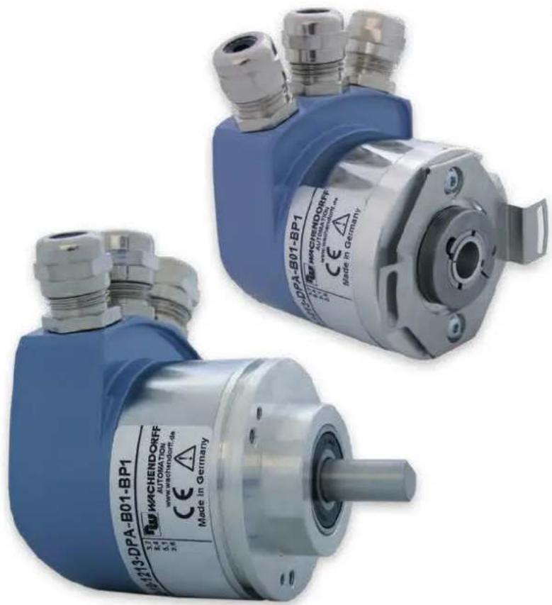
There are various mechanical variants for the WDGA series with PROFIBUS-DP. The decisive factors here are the design, with or without bus cover, the type of flange shape and the type of shaft (solid or end hollow shaft). The size is determined by the diameter of the flange with 58 mm. Figure 3.1 shows examples for the WDGA series with PROFIBUS-DP.

natural_image
Three identical mechanical encoders with metallic shafts and connectors, shown from different angles (no visible text or symbols on the devices themselves)Figure 3.1: WDGA with PROFIBUS-DP
The solid or end hollow shaft is connected to the rotating part whose angular position or speed is to be measured. Cable or connector outlets form the interface for connection to the PROFIBUS network (see sections 3.5, 3.6 or 3.8). Status LEDs in the cover indicate various states of the encoder during operation. They support the configuration of the encoder or troubleshooting in the field (see section 3.4). The flange holes or the supplied spring plates are used for fastening to the machine or in the application.
3.2 WDGA - Basics
In the following sections, the basic functions of an absolute encoder are described.
In contrast to incremental encoders, absolute encoders output their position value as a digital number via a fieldbus. A distinction is made between singleturn and multiturn encoders.
In addition to the simple output of the position value, most rotary encoders allow a certain degree of parameterization, such as the selection of the positive direction of rotation, the setting of the position value to a reference value at a defined physical position and the scaling of the position value to any resolution and a limited measuring range. In this way, the development effort in the control program is reduced and the computing capacity of the control is relieved.
3.2.1 Singleturn - ST
Measuring the angle from 0irc to 360irc using a shaft is the minimum function of a rotary encoder. The sensor system is based on the optical or magnetic scanning of a measuring standard on the encoder shaft.
3.2.2 Multiturn - MT (EnDra®)
A multiturn encoder allows the number of revolutions to be counted. This is realized via a revolution counter. EnDra® technology is used for the WDGA encoders to ensure that the corresponding information is retained even when the encoder is de-energized. Buffer batteries and gearboxes, which require a comparatively large installation space and require corresponding maintenance, can thus be replaced.
3.2.3 Direction of rotation
By a simple two's complement (invert each bit and add "1") of the position value, the positive direction of rotation can be reversed.
3.2.4 Preset
At a certain physical position, the encoder can be assigned a desired position value. This must lie within the measuring range so that the position value is correlated with a physical reference position. The difference between the current position value and the desired value is calculated. This is stored in a non-volatile memory and added to the position value as an offset.
3.2.5 Scaling
The scaling parameters can be used to adjust the position value to exactly match the physical quantity to be measured. The scalable parameters are "Measuring units per revolution (MUPR)" and "Total measuring range in measuring units (TMR)".
The scaling parameter "Measuring units per revolution (MUPR)" - increments per revolution - indicates the resolution of the position value per revolution (also: ST resolution). The value corresponds to 360°. This means that if a value of 3600 Cts is parameterized, the encoder outputs the position in 0.1° steps (see equation (2)).
MUPR = ST = 3 6 0 0 Cts 1
angular steps = angle of one revolution MUPR = 3 6 0 ^ irc3 6 0 0 Cts = 0, 1 ^ irc / Cts 2
The scaling parameter "Total measuring range in measuring units (TMR)" - maximum total measuring range of the position value (singleturn and multiturn multiplied) - indicates the total resolution of the encoder. If the position value TMR reaches - 1, it jumps back to 0 and vice versa.
As a rule, the parameter TMR is selected so that it is an integer multiple of the "Measuring units per revolution (MUPR)" (see equation (4)), so that the zero point is always on the same position of the encoder shaft.
TMR = 3 6 0 0 0 Cts 3
MT = TMRMUPR = 3 6 0 0 0 Cts3 6 0 0 Cts = 1 0 4
In exceptional cases it is adequate that TMR is not an integer multiple of MUPR. For example, if in a plant a transmission ensures that the desired measured variable moves 10% faster in relation to the encoder shaft than the encoder shaft.
Then a setting of MUPR = 3960 Cts and TMR = 36000 Cts would ensure that the faster but not directly measurable wave can be measured with a resolution of 0.1irc and over a range of 10 revolutions. Normally, the number of revolutions could be calculated by dividing the position value by MUPR. In this case, however, it is necessary to divide by 3600 Cts, otherwise the result would be the number of revolutions of the encoder shaft and not that of the faster shaft of the system.

- Note that measurement errors occur if the result of this formula is a comma separated number.
3.3 Default settings
3.3.1 General information
At factory default, the PROFIBUS address is always set to "126".

- The PROFIBUS address can be set by Wachendorff according to customer requirements. Please contact our technical application support (see section 9).
3.3.2 Rotary encoder - with bus cover

- By default, the decimal rotary encoding switches are set to "00". The change of the address can be found in section 4.4.2.
The termination is set to "ON" by default. See section 4.4.3 for more information.
The connection terminal is included with the BP1 variant. This enables user-friendly installation of the supply and signal lines. Section 4.4.4.1 describes how to mount the cables to the terminal.
3.3.3 Rotary encoder - without bus cover
The change of the default PROFIBUS address "126" can be found in section 4.4.1.
3.4 LED signalling
Two status LEDs in the cover signal different encoder states and support diagnostics and troubleshooting in the field (see Table 3.1). The BUS LED signals the status of the fieldbus and the DEV LED signals the status of the encoder.
| BUS LEDbicolour | DEV LEDbicolour | significance | cause |
| ○ | ○ | no power | Power supply is missing. |
| ● | ● | No connection to another deviceCriterion: No data exchange | - Bus not connected- Master not available/switched off- The encoder is ready for operation, but has not yet received any configuration data after switching on the supply voltage.Possible causes:- Address incorrectly set- Bus cables connected incorrectly |
| ●●●* | ● | Parameterization or configuration error. If master-slave communication is functioning.Criterion:Data exchange correctThe slave does not switch to the data exchange mode. | - Slave is parameterized incorrectly- Slave is incorrectly configured |
| ● | ● | system outage | Diagnosis available, slave in data exchange mode |
| ● | ● | Normal operation:exchange of data Slave and operation ok |
Table 3.1: LED signalling
Explanation of symbols and asterisks:
○ LED off
/LED on
*Flashing frequency 0.5 Hz, minimum display time 3 s
3.5 BP1 - Bus cover with 3x PG screw connection
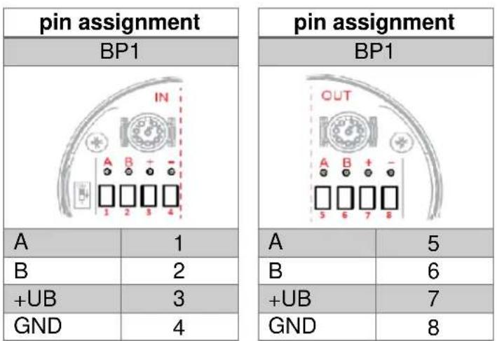
The character string "BP1" in the order code identifies an encoder with bus cover (see Figure 3.2). The electrical connection is made in the bus cover via the three PG cable glands on the connection terminal. The pin assignment of the connection terminal can be found in the Table 3.2.

Figure 3.2: WDGA58A, BP1 - 3x PG screw connection
other
pin assignment | Pin | Value | |---|---| | BP1 | 1 | | IN | 2 | | A | 3 | | GND | 4 | pin assignment | Pin | Value | |---|---| | OUT | 5 | | A | 6 | | B | 7 | | GND | 8 |Table 3.2: Pin assignment - BP1

- Further details can be found in the corresponding data sheet: www.wachendorff-automation.com
3.6 BP2 - Bus cover with 3x M12
The character string "BP2" in the order code identifies an encoder with bus cover (see Figure 3.3). The electrical connection is made to the bus cover via the 2x M12 plug and 1x M12 socket. The pin assignments of the plugs or sockets can be found in the Table 3.3.

Figure 3.3: BP2 - 3x M12
| pin assignment | |
| BP2 | |
| Plug(A) | M12x1,4-pole,A-coded |
| +UB | 1 |
| n.c. | 2 |
| Signal 3 | 3 |
| n.c. | 4 |
| pin assignment | |
| BP2 | |
| Socket(B) | M12x1,5-pole,B-coded |
| BUS | OUT |
| n.c. | 1 |
| A | 2 |
| n.c. | 3 |
| B | 4 |
| n.c. | 5 |
| pin assignment | |
| BP2 | |
| Plug(C) | M12x1,5-pole,B-coded |
| BUS | IN |
| n.c. | 1 |
| A | 2 |
| n.c. | 3 |
| B | 4 |
| n.c. | 5 |
Table 3.3: Pin assignment - BP2
 | • Further details can be found in the corresponding data sheet: www.wachendorff-automation.com |
3.7 DB4 - without bus cover 2x M12, 1x M8
The character string "DB4" in the order code identifies an encoder without bus cover (see Figure 3.4). The electrical connection is made via 2x M12 and 1x M8. The pin assignments of the plugs or sockets can be found in the Table 3.4.
Figure 3.4: DB4 - 2x M12, 1x M8
| pin assignment | |
| DB4 | |
 | |
| Plug (A) | M8x1, 4-pole |
| +UB | 1 |
| n.c. | 2 |
| GND | 3 |
| GND | 4 |
pin assignment
| DB4 | |
| Socket(B) | M12x1,5-pole,B-coded |
| BUS | OUT |
| 5 V DP | 1 |
| A | 2 |
| GND DP | 3 |
| B | 4 |
| n.c. | 5 |
pin assignment
| DB4 | |
 | |
| Plug(C) | M12x1,4-pole,B-coded |
| BUS | IN |
| n.c. | 1 |
| A | 2 |
| n.c. | 3 |
| B | 4 |
Table 3.4: Pin assignment - DB4

- Further details can be found in the corresponding data sheet: www.wachendorff-automation.de
3.8 SD9/SE9 - without bus cover, D-Sub
The character string "SD9 or SE9" in the order code identifies an encoder without bus cover with D-Sub socket. The electrical connection is made via a 9-pin D-Sub female connector. The D-Sub female connector is arranged axially (SD9) or radially (SE9) (see Figure 3.5). The pin assignment of the socket can be found in the Table 3.5.


Figure 3.5: SD9/SE9 - D-Sub
| pin assignment | |
| SE9 / SD9 | |
| socket | D-SUB |
| n.c. | 1 |
| GND | 2 |
| B | 3 |
| n.c. | 4 |
| GND DP | 5 |
| 5 V DP | 6 |
| +UB | 7 |
| A | 8 |
| n.c. | 9 |
| shade | case |
Table 3.5: Terminal assignment - SD9/SE8

- Further details can be found in the corresponding data sheet: www.wachendorff-automation.com
3.9 Rotary encoder and bus cover label
The Figure 3.6 shows an example of the encoder label. Table 3.6 shows the meaning and the corresponding field position.

Figure 3.6: Encoder label for BP1
| field position | significance |
| 1st line | order code |
| 1st column, 1st row | Singleturn and multiturn resolution |
| 1st column, 2nd row | permissible voltage supply |
| 1st column, 3rd row | Interface + software version |
| 1st column, 4th row | Serial number of the encoder |
| 2nd column | Terminal assignment of the connection terminals |
Table 3.6: Encoder label
If you have a rotary encoder with bus cover, further information can be found on the bus cover label (see Figure 3.7). Among other things, you will also find the serial number of the encoder, the software version of the bus cover, the pin assignment and the accessible line connections (see Table 3.7). In the BP2 version, the pin assignment of the plugs or sockets is preceded by the identification of the cable connection (e.g. A1: cable connection A, pin 1 of the M12x1 plug).
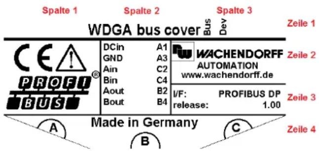
Figure 3.7: Encoder label for BP2
| field position | significance |
| 2nd column, 2nd row + 3rd row | Pin assignment (here: BP2) |
| 3rd column, 1st row | LED designation |
| 3rd column, 3rd row | Interface + software version |
| 4th line | Accessible line connections |
Table 3.7: Bus cover label
3.10 GSD file
The properties and functionalities of the encoder are described in the GSD file. For the user, there are project planning tools (see chapter 5 Project planning) available to enable the desired settings to be made on the encoder in a user-friendly manner.
In Table 3.8 you will find an overview of the available GSD files and the corresponding classes of WDGA encoders.
| WDGA Encoder Functionality | GSD file |
| Class 4 (DP-V1/V2 functions) | WDGA0DD2 |
Table 3.8: Overview - GSD files
 | • You can find the GSD file on our website:www.wachendorff-automation.com |
4 Installation
4.1 General information
The safety instructions must be observed when installing the encoder (see chapter 2.3).

- When electrically connecting the encoder, a distinction must be made between whether the encoder is designed with or without bus cover (see section 4.4 or 4.5).

- For the mechanical and electrical connection, please observe the safety instructions (see chapter 2 Safety information).
4.2 Mechanical connection
4.2.1 Shaft encoder

- Always connect encoder shaft and drive shaft via a suitable coupling. The coupling compensates the play of both shafts in radial and axial direction.
- The encoder shaft and drive shaft must never touch each other.
- The maximum axle loads of the drive and the encoder must be observed.
- The encoder can simply be screwed to a suitable plate via the four holes in the flange on the shaft side.
- Another way of mounting the encoder is to use clamping eccentrics.

- Suitable accessories can be found on our website: www.wachendorff-automation.com
4.2.2 Hollow shaft encoders

- Plug the encoder completely onto the drive shaft.
- Lock with the setscrews in the encoder shaft by screwing on the drive shaft.
- The encoder has a spring plate which absorbs the torque generated in the flange. It is attached to the machine with two screws. The spring plate is "spring-loaded" to compensate for vibrations and play on the drive shaft and to avoid overloading the encoder bearings.

- Suitable accessories can be found on our website: www.wachendorff-automation.com
4.3 Shielding
Suitable measures must be taken to ensure that the system structure of the system is EMC-compatible.
Electromagnetic interference is mainly caused by switching operations, power converters and circuit breakers. In addition, overvoltage and lightning may damage a field device. This can lead to a system failure of the system. The PROFIBUS stations, PROFIBUS cable shields and other components must be connected to the equipotential bonding rail so that electromagnetic interference can be dissipated. With PROFIBUS-DP, earthing is done via a common equipotential bonding rail.

- The encoder and the connection cables must be completely shielded.
- The cable shields must be connected on both sides and connected to the protective earth (PE).
- The encoder housing must also be connected to protective earth PE).
Detailed information on cabling and shielding can be found, among other things, in special PNO documents. For example, the PROFIBUS Mounting Directive (Order No: 8.021); PROFIBUS Technical Directive - Installation Directive PROFIBUS-DP/FMS Version 1.0 (September 1998) and the PROFIBUS Planning Directive Version 1.0 (August 2009).

- If necessary, please refer to the relevant literature for information on intended EMC measures.
4.4 Connecting the encoder - with bus cover
4.4.1 General information
The bus cover of the rotary encoder (see Figure 4.1) is loosened using two fastening screws and a screwdriver. The bus cover can then be removed axially from the rotary encoder. The PROFIBUS address and the PROFIBUS termination are set accordingly via the bus cover (see section 4.4.2 or 4.4.3). Once the settings have been made, the bus cover is reattached to the rotary encoder. For this purpose, the M12 sockets of the bus cover and the M12 plugs of the encoder are joined together. Finally the screws of the bus cover are tightened again in the same direction.
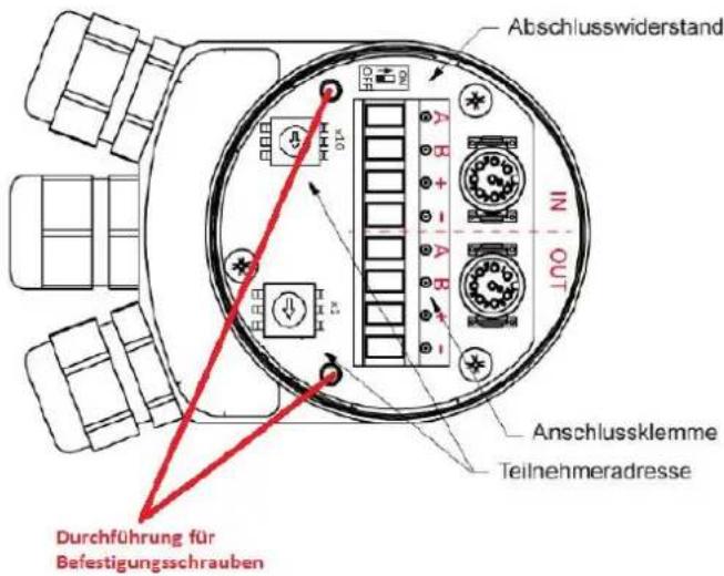
Figure 4.1: PROFIBUS bus cover

- In order for the shielding to be optimally connected, the bus cover must sit completely flat all around and be screwed down.
4.4.2 Setting the slave address

- To prevent collisions on the bus, it is recommended to connect the encoder to an independent PROFIBUS master first. This does not endanger the availability of an operational system.
• Each PROFIBUS address may only be assigned once. - The PROFIBUS address 126 can only be used for commissioning purposes (not for data exchange).
- When assigning the PROFIBUS address between 0 and 2, it should be noted that these are frequently used for PROFIBUS masters.
The slave address is set via the two decimal rotary coding switches. The permissible address range is between 0 and 99. For a more significant address (100 - 126), the setting must be made by software (see 4.5.1). The decimal rotary encoding switches must be set to x10 = 0 and x1 = 0.
The value of the decimal rotary encoding switches works as shown in the following example (Figure 4.2). The decimal rotary coding switch on the bus cover board indicates the values. The x10 mark indicates the tens digit and the x1 mark indicates the units digit.

Figure 4.2: Rotary decimal encoding switch - bus cover

- The slave address is read in and accepted exclusively during the start of the encoder.
4.4.3 Termination
If the encoder is the last PROFIBUS station, termination must be switched on (see also section 7.3.3). Switching on takes place via the dip switch in the bus cover. The label of the switch position is located above or below the dip switch on the bus cover board. If the encoder is not the last PROFIBUS station, the termination must be switched off. Figure 4.3 shows an example of the dip switch.

Figure 4.3: Dip switch - Bus cover
If the termination is switched on, then the PROFIBUS-DP is completed, i.e. further PROFIBUS stations behind it are then disconnected.

- In this case, only the PROFIBUS bus "IN" is connected (see 4.4.4.1 or 4.4.4.2).
- The continuing PROFIBUS bus "OUT" is disconnected.
4.4.4 Connecting the signal and supply lines
4.4.4.1 BP1 - 3x PG screw connection

- The pin assignment of the terminal is shown in Table 3.2.
The supply line must be connected once in the connection terminal. The supply "+" (also: +UB) and "-" (also: GND) in the "IN" and "OUT" marked area of the terminal are internally looped through. The positive voltage +UB (see encoder label) is applied to the connection with the "+"-marked area of the connection terminal. GND is connected to the connection with the "-" marked area of the connection terminal.
The incoming PROFIBUS cables A (green) and B (red) are connected to the terminal in the "IN" marked area. The further PROFIBUS lines (A and B), if required, are connected to the terminal with the "OUT" marked area. A-"IN" and A-"OUT" or B-"IN" and B-"OUT" are internally looped through when termination is off.

Figure 4.4: BP1 connections - PG screw fitting

- Prevent the supply voltage from coming into contact with the data lines A and B. This can damage the electronics.
- Avoid crossing the PROFIBUS cable and the supply cable.
- Close unused PG connections with sealing caps.
An installation example is shown below:
Figure 4.5 shows the recommendation for the lengths of stripping of the wires for connection to the terminal.

Figure 4.5: Lengths for stripping - Schematic
Figure 4.6 shows a stripped PROFIBUS standard cable with the contact sleeve for the braided shield. The wires are stripped according to Figure 4.5.

Figure 4.6: Stripped PROFIBUS standard cable
The shortened braided shield (length see Figure 4.5) is put over the contact sleeve (see Figure 4.7).

natural_image
Close-up of a cable with exposed copper wires and insulation, showing purple filament, green wire, and red core (no text or symbols visible)Figure 4.7: Shielding, stripped cores
The pre-assembled PROFIBUS standard cable is inserted through the PG screw connection (see Figure 4.8).

Figure 4.8: Preconfigured PROFIBUS standard cable through PG cable gland
The wires are connected to the according connection terminal. The connection terminal is plugged into the bus cover. The standard PROFIBUS cables are screwed to the cap nut (see Figure 4.9).
The supply line is connected according to a similar principle.
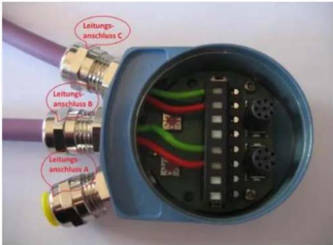
- The pin assignment for the BP2 variant can be found in Table 3.3.
A 4-pole M12 socket with A coding is required for the supply line. Pin 1 has +UB (see encoder label) and pin 3 has GND. Shielding should rest on the union nut.
The PROFIBUS cable for the incoming bus requires a 5-pin M12 socket with B coding. Pin 2 contains the A signal and pin 4 contains the B signal. The other pins are unused.
A 5-pin M12 connector with B coding is required for the PROFIBUS cable. The A signal is on pin 2 and the B signal on pin 4. All other pins are not assigned.

Figure 4.10: BP2 connections - 3x M12

- If the termination is set to "ON", the continuing PROFIBUS is disconnected.
- The shield should rest on the union nut of the plugs or sockets for both the supply and PROFIBUS cables.
4.5 Connecting the encoder - without bus cover
4.5.1 Setting the slave address

- To prevent collisions on the bus, it is recommended to connect the encoder to an independent PROFIBUS master first. This does not endanger the availability of an operational system.
• Each PROFIBUS address may only be assigned once. - The PROFIBUS address 126 can only be used for commissioning purposes (not for data exchange).
- When assigning the PROFIBUS address between 0 and 2, it should be noted that these are frequently used for PROFIBUS masters.
The slave address is set exclusively via the PROFIBUS master.
How you can set the slave address via a PROFIBUS master is shown in the example in Figure 4.11. Software: Simatic Manager - Step7).

Figure 4.11: Step7 - "Assign PROFIBUS Address..."

- The PROFIBUS address set here is assigned in the hardware configurator (see section 5.3.1).
- If the PROFIBUS is terminated on both sides, the PROFIBUS address can be assigned via a programming adapter (USB to PROFIBUS). No control is required for this.

Figure 4.12: Step7 - Assign PROFIBUS address
4.5.2 Termination
The encoder does not provide an internally adjustable termination. If the encoder is the last PROFIBUS station, you must perform an external termination. The exemplary external termination (see Figure 4.13) is carried out by connecting this termination to the continuing PROFIBUS bus "OUT" (line connection B) (see section 4.5.3.1).

natural_image
3D rendering of a metallic cylindrical connector with threaded ends and a small orange tip (no text or symbols visible)Figure 4.13: External PROFIBUS termination

- Suitable accessories can be found on our website: www.wachendorff-automation.com
4.5.3 Connecting the signal and supply lines
- The pin assignment for the DB4 variant can be found in Table 3.4.
A 4-pole M8x1 socket with A coding is required for the supply line. Pin 1 has +UB (see encoder label) and pin 3 and 4 have GND. Shielding should rest on the union nut.
For the incoming PROFIBUS, a PROFIBUS cable with a 4-pin M12 socket with B coding is connected. The A signal is on pin 2 and the B signal on pin 4. Pin 1 and 2 are not assigned.
The continuing PROFIBUS is connected with a PROFIBUS cable with a 5-pin M12 connector with B coding. Pin 2 contains the A signal and pin 4 the B signal.
If the rotary encoder is connected as the last PROFIBUS station, an M12 PROFIBUS termination can be connected to this connection (BUS-OUT) (see Figure 4.13). The required galvanic isolated 5 V voltage (signal designation: 5 V DP) is applied to pin 1. The corresponding ground GND DP is on pin 3.

Figure 4.14: DB4 connections - 2x M12, 1x M8
4.5.3.2 SD9/SE9 - D-Sub

- The pin assignment for the SD9/SE9 variant can be found in Table 3.5.
Connect a 9-pin PROFIBUS D-Sub plug to the D-Sub socket. These are available in various versions on the market (e.g. as diagnostic plugs, with or without bus termination, etc.).
5 Project planning
5.1 General information
The following examples are based on the program "STEP 7" (version 5.5). If not already available, you need the corresponding hardware, a DPM1 master, DPM2 master, DP slave (WDGA encoder with PROFIBUS) and the corresponding GSD file (see section 3.10).
5.2 Installing the GSD file
The GSD file of the WDGA encoder with PROFIBUS is installed in the hardware configurator "HW Config" (see Figure 5.1). Further information on the GSD file can be found in section 3.10.
The GSD file for class 4 can be found on our website: Download - GSD file - Close the opened hardware projects.
At "Extras" -> "Install GSD-files..." Select your corresponding storage location.
GSD file "Install".

Figure 5.1: GSD file - STEP 7
Then update the "Hardware Catalogue".

- In the "Hardware Catalogue" at "PROFIBUS-DP", "Other field devices", "Encoder", "Wachendorff Automation", "WDGA PROFIBUS ClassX" (X = 2 or 4), the WDGA encoder appears (see Figure 5.2).
- There appear the "WDGA PROFIBUS ClassX" modules (X = 2 or 4).
- Modules according to the configuration data of class 4 (see Table 6.1) can be selected here.

Figure 5.2: Hardware Configurator - STEP 7
5.3 Integration of the WDGA
If not already available, configure a DPM1 master in the hardware configurator.
In Figure 5.3 different areas of the "HW Configurator" are marked.
At "Hardware Catalog" click on the "WDGA PROFIBUS ClassX" module (X = 2 or 4) and drag it into the "Station Window" to the fieldbus (here: "PROFIBUS(1): DP master system(1)").
Then click once on the "WDGA icon". The assembly is displayed in the Station Properties window.
Drag your desired "WDGA PROFIBUS ClassX" module (X = 2 or 4) from the "Hardware Catalog" into the "Station Properties Window" to "Slot 1".

Figure 5.3: HW configuration - STEP 7
5.3.1 Communicating the slave address
The slave address previously set in the WDGA (with bus cover: see section 4.4.2; without bus cover: see section 4.5.1) must be communicated in the hardware configuration (see Figure 5.4).
Double click on the "WDGA-Icon".
Under "General", "PROFIBUS. . . "Enter the corresponding slave address in the "Parameters" field.
Select your configured PROFIBUS in the "Subnet" and confirm with "OK".

- If you have a WDGA encoder with bus cover, make sure that the display of the rotary coding switches is consistent with the display in the "Station window".

Figure 5.4: Address assignment - "HW configuration" STEP 7
5.3.2 Setting I/O addresses
The I/O addresses are the S7 addresses under which the encoder is addressed in the controller. The controller uses these to access the input and output data of the encoder. The I/O addresses are assigned via the "Properties-DP-Slave" window (see Figure 5.5).
Double click on the line of the attached "WDGA Module" in the "Station Properties Window".
Enter the desired I/O address in the "Properties - DP Slave" window and confirm with "OK".
Identical addresses are permitted for the I/O addresses.

Figure 5.5: I/O addresses - STEP 7
 | ·Depending on the controller type, there may be restrictions for the permissible value range of the I/O addresses that do not directly lead to error messages. If the access to the data is not possible via the addresses Exxx or Axxx, but only via PExxx and PAxxx, too high values may have been entered here. Avoid overlapping with other slaves! |
5.3.3 Parameterization - Class 4
Via the "Properties - DP Slave" window the parameterization can be carried out (see Figure 5.6).
Click on the parameters to carry out your parameterization:
- "code sequence" - change of the direction of rotation (see section 6.3.1).
- "class 4 functionality" - Activation of class 4 functionalities (see section 6.3.2).
- "G1_XIST1 preset control" - Effect of the preset on the position value in G1_XIST1 (see section 6.3.3).
- "scaling function control" - Activation of scaling (see section 6.3.4).
- "Alarm channel control" - If "Alarm channel control" is deactivated, only the 6 byte long standard diagnosis is output via the diagnosis (only has an effect in compatibility mode, see section 6.3.5).
- "Compatibility mode" - compatibility with the older encoder profile version 3.1 (see section 6.3.6).
- "Measuring units per revolution" - Enter ST resolution (see section 6.3.7).
- "total measuring range" - Enter the total resolution (see section 6.3.8).
- "Maximum master sign-Of-life failures" - This parameter sets the upper limit of the isochronous mode error counter to 10 times the value (only has an effect in compatibility mode, see section 6.3.9).
- "Speed measuring unit" - Define the unit of the speed value (see section 6.3.10).
- "64 bit MUPR (lower half)" - 0-31 bit part of the ST resolution; always the same MUPR (see section 6.3.7).
- "64-bit MUPR (upper half)" - 32-64-bit part of the ST resolution; Always 0 (see section 6.3.7).
- "64Bit-TMR (lower half)" - 0-31 bit part of the total resolution (see section 6.3.8).
- "64Bit-TMR (upper half)" - 32-64 bit part of the total resolution (see section 6.3.8).

- Once the hardware configuration has been completed, it can be translated and loaded into the target system (DPM1).
• Make sure that you have also translated and not only saved.
5.3.4 Set diagnostic address
To evaluate diagnostic messages from the encoder, a diagnostic address must be assigned (see Figure 5.7).
Enter the diagnostic address in the "Properties - DP Slave" window.

Figure 5.7: Diagnostic addresses - STEP 7

- The diagnostic address can be located in the entire peripheral area of the controller.
- The diagnostic address does not occupy an I/O address.
- The assignment of the diagnostic address is only necessary if the diagnostic functions are used.
- Reading the diagnosis see section 5.8.
5.4 Creating the Symbol Table
Create your symbol table or complete your existing one if necessary.
Open the symbol table as shown in Figure 5.8.

Figure 5.8: Opening the symbol table - STEP 7
Enter your own symbol name under "Symbol".
Enter your specified I/O address range under "Address". Make sure that you select the word sizes according to the sizes of the words to be addressed (e.g. 32-bit position value see PROFIBUS manual or Fehler! Verweisquelle konnte nicht gefunden werden.). See example in Figure 5.9.
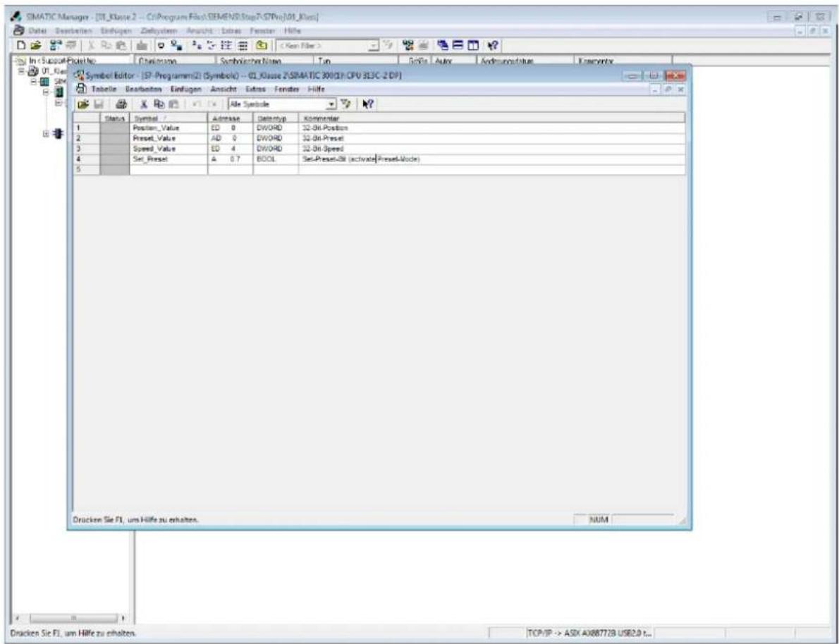
Observe position and speed:
Open the variable table (as shown in Figure 5.10).
Enter your symbol names under "Symbol".
Select the desired "display format".
At "Status value" the current values appear (e.g. position and speed), which you can observe with the "glasses icon".
![Var - [VAT1 -- @01_Klasse 2\SIMATIC 300(1)\CPU 313C-2 DP\S7-Programm(2) ONLINE] Tabelle Bearbeiten Einfügen Zielsystem Variable Ansicht Extras Fenster Hilfe Operand Symbol Anzeigeformat Statuswert Steuerwert 1 ED 0 "Position_Value" BIN 2#0000_0000_0000_0011_1111_0111_0110_1111 2 ED 4 "Speed_Value" BIN 2#0000_0000_0000_0000_0000_0000_0000_0000 3 01_Klasse 2\SIMATIC 300(1)\...\S7-Programm(2) RUN Abs < 5.2](/content/2026/05/1016387/images/33cb2dafa42118bcc6b3d074aca74f1344e4136a59c925df33a08a21757161f4.jpg)
Figure 5.10: Variable table - STEP 7
Load position and velocity into a control program:
Open your control program ("LAD/SAWL/FUP" window).
Load with "L" the position/speed with the symbol name assigned by you and transfer it with "T" into a marker selected by you.
See the example in the Figure 5.11.

Figure 5.11: Loading values into a control program - STEP 7
5.6 Set preset value - Class 4
To set a preset, you first need the S7 example. The preset routine is performed within the FC2. Several steps are required to set the preset value:
Step one:
Open the variable table "VAT_Control" (see Figure 5.12).
Set the control value of "STW2_ENC" to the hex value 0400 ("STW2_ENC" - bit 10). The encoder is now in "Control by PLC" mode (see Table 6.9 or section 6.4.9.1).
Use the "control variable" button to control the value.

- Valid value range for the preset: TMR-1.
- The value of G1_XIST1 and G1_XIST2 must be identical, otherwise there is an error (see section 5.7).

Figure 5.12: Variable table "VAT_Control" - "STW2_ENC" = 400
Step two:
Enter the desired preset value for the control value with the symbol name "newPresetValue" (Figure 5.13).
- Use the "control variable" button to control the value.

Figure 5.13: Table of variables "VAT_Control" - "newPresetValue"

- With the "Observe" button you can observe the changing status values.
Step three:
Set the control value of "G1_STW" to the hex value: 1000 (see Figure 5.14).
Meaning of hex value: 1000 (set bit 12 to "1") see Table 6.7.
Use the "control variable" button to control the value.
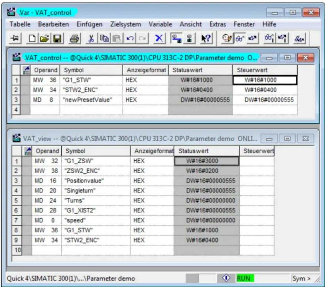
Figure 5.14: Variable table "VAT_Control" - "G1_STW" = 1000
Step four:
Step 3 changes the status value in the variable table "VAT_View" (see Figure 5.14) from hex value: 2000 to hex value: 3000.
Meaning of hex value: 3000 (bits 12 and 13 set to "1") see Table 6.8.
Step five:
Set the control value of "G1_STW" to the hex value: 0000 (see Figure 5.13).
This changes the status value in the variable table "VAT_View" (see Figure 5.13) from hex value: 3000 back to hex value: 2000 (bit 13 set to "1").
5.7 Error management

- If the value of G1_XIST1 is not equal to the value of G1_XIST2, an error has occurred.
- The status value in the variable table "VAT_View" (see Figure 5.15) changes from hex value: 2000 to hex value: 9000 (bits 15 and 12 set to "1"). Meaning see Table 6.8.
- For further details see section 6.4.5.1.
• Note the valid value range of: TMR-1.
If there is an error (see Figure 5.15), it must be acknowledged.

Figure 5.15: Variable table "VAT_View" - Error code in G1_XIST2
Set the control value of "G1_STW" to the hex value: 8000 (see Figure 5.16). Repeat this procedure until all errors have been confirmed.
Meaning of hex value: 8000 (set bit 15 to "1") see Table 6.7.
Finally, set the control value of "G1_STW" back to the hex value: 0000.

Figure 5.16: Variable table "VAT_View" - error in G1_XIST2 acknowledged
 | In the variable table VAT_View, "Positonvalue" (G1_XIST1) and "G1_XIST2" are the same again. The errors were acknowledged.This changes the status value in the variable table "VAT_View" (see Figure 5.13) from hex value: 9000 to hex value: 2800 (bits 13 and 11 set to "1").Meaning see Table 6.8 |
5.8 Reading the diagnosis
As a rule, the DP master retrieves the diagnosis automatically without any programming being necessary. However, the processing and logging of errors must be done in the control program. If this is not done, the controller may automatically switch to a safe state.

- It is not recommended to simply discard the diagnostic data to avoid stopping the control. If necessary, measures must be taken to ensure the safe operation of a system.
- Ensure that your diagnostic evaluation is carried out so that the validity of the values is guaranteed.

- Set diagnostic address see section 5.3.4.
- Further details on diagnostics within the control program can be found in the example programs (see section 5.9).
- Further information: - General diagnostics: see section 7.10 - Diagnosis class 4: see section 6.5
5.9 S7 sample program

- S7 sample programs can be downloaded from our website: www.wachendorff-automation.com
6 Encoders - Class 4
6.1 General information
Encoder profile 4.1 describes encoder classes 3 and 4. Like class 1, class 3 contains only the basic functionality required for an encoder. Class 4 functions are optional in a Class 3 device, whereas a Class 4 encoder must support all Class 4 functions.
The encoder profile 4.1 is based on the drive profile PROFIdrive 4.1. The relevant encoder functions from PROFIdrive were incorporated into the encoder profile almost unchanged, so that extensive compatibility was achieved. Since PROFIdrive was designed for compatibility with PROFINET, porting the control software from PROFIBUS-DP to PROFINET is made easier.

- The encoder profile 4.1 uses DP-V0 as well as DP-V1 and DPV2 functions.
6.2 Configuration
The corresponding configuration data for a class 4 encoder can be found in Table 6.1.
| designation | telegram | significance |
| Telegram 81 | 81 | Input data (6 words):Slave sign of life, preset + sensor parking, 32-bit position, 32-bit position or error code Output data (2 words):Master sign of life, preset + sensor parking |
| Telegram 82 | 82 | Input data (7 words):81 + 16-bit speedOutput data (2 words):Master sign of life, preset + sensor parking |
| Telegram 83 | 83 | Input data (8 words):81 + 32-bit speedOutput data (2 words):Master sign of life, preset + sensor parking |
| Telegram 84 | 84 | Input data (10 words):Slave sign of life, preset + sensor parking, 64-bit position, 32-bit position or error code, 32-bit speedOutput data (2 words):Master sign of life, preset + sensor parking |
| Telegram 59000(81 with debug) | 59000 | Input data (7 words):81 + DebugOutput data (3 words):Master Life Sign, Preset + Sensor parking Debug |
Table 6.1: Configuration data

- WDGA encoders support all 5 configurations
6.2.1 Telegram structures
The telegram structures that can be used for the configuration of the class 4 encoder are shown in Table 6.2.

- For the meaning of the control and status words see section 6.4.
- The configuration telegrams are reflected in the "HW Config" window of STEP7 (see section 5.3).
| Nr. | Dir. | Datenwort | |||||||||
| 1 2 3 | 4 5 6 7 8 | 9 10 | |||||||||
| 81 | SPS -> ENC | STW2_ENC | G1_STW | ||||||||
| ENC -> SPS | ZSW2_ENC | G1_ZSW | G1_XIST1 | G1_XIST2 | |||||||
| 82 | SPS -> ENC | STW2_ENC | G1_STW | ||||||||
| ENC -> SPS | ZSW2_ENC | G1_ZSW | G1_XIST1 | G1_XIST2 | NIST_A | ||||||
| 83 | SPS -> ENC | STW2_ENC | G1_STW | ||||||||
| ENC -> SPS | ZSW2_ENC | G1_ZSW | G1_XIST1 | G1_XIST2 | NIST_B | ||||||
| 84 | SPS -> ENC | STW2_ENC | G1_STW | ||||||||
| ENC -> SPS | ZSW2_ENC | G1_ZSW | G1_XIST3 | G1_XIST2 | NIST_B | ||||||
| 860 | SPS -> ENC | G1_XIST_PRESET_A | |||||||||
| ENC -> SPS | G1_XIST1 | NIST_B | |||||||||
| 59000 | SPS -> ENC | STW2_ENC | G1_STW | DEBUG_STW | |||||||
| ENC -> SPS | ZSW2_ENC | G1_ZSW | G1_XIST1 | G1_XIST2 | DEBUG_ZSW | ||||||
Table 6.2: Telegram structure 81-84 and 59000

- Standard telegrams (81-84) from the PROFIdrive profile (see section 7.15.2).
- Device manufacturer specific telegram (59000). See PROFIdrive profile under section 7.15.2).
- The debug control word is additionally implemented here (see Section 7.16).
6.2.2 Signal list
The following Table 6.5 shows an overview of the control and status words. Refer to the following sections under 6.4 details.
| abbreviation | significance | data | Length [bit] |
| G1_STW | control wordSensor 1 control word | initial data | 16 |
| STW2_ENC | master vital signsEncoder Control word 2 | initial data | 16 |
| G1_ZSW | status wordSensor 1 status word | input data | 16 |
| G1_XIST1 | 32-bit position valueSensor 1 position actual value 1 | input data | 32 |
| G1_XIST2 | 32-bit position value or error codeSensor 1 position actual value 2 | input data | 32 |
| G1_XIST3 | 64-bit position valueSensor 1 position actual value 3 | input data | 64 |
| NIST_A | 16-bit speedSpeed actual Value A | input data | 16 |
| NIST_B | 32-bit speedSpeed actual Value B | input data | 32 |
| ZWS2_ENC | slave life signsEncoder Status word 2 | input data | 16 |
Table 6.3: Signal List - Overview
6.3 Parameterisation
Since the order of the parameter blocks can be selected arbitrarily, the octet number also depends on the order. To determine the actual octet number of a parameter, add the corresponding offset. For example 11, if this block directly follows the DP-V1 parameters. The individual parameters are explained below.
Table 6.6 and Table 6.7 show the parameter block for the encoder parameters.
| parameter | data type | octet | range of values |
| block length | Unsigned 8 | 1 | 21 or 41 |
| block type | Unsigned 8 | 2 | always 129 |
| slot | Unsigned 8 | 3 | always 2 |
| Reserved | 4 | always 0 | |
| Class 4 functionality | bit | 5 / bit 1 | Enableddisabled |
| G1_XIST1 Preset control | bit | 5 / bit 2 | Enableddisabled |
| Scaling function control | bit | 5 / bit 3 | Enableddisabled |
| Alarm channel control | bit | 5 / bit 4 | Enableddisabled |
| Compatibility mode | bit | 5 / bit 5 | Enableddisabled |
Table 6.4: Parameter block for encoder parameters - Part 1
| parameter | data type | octet | range of values |
| Reserved | 5 / bit 5 | 0 | |
| Measuring units per revolution | Unsigned 32 | 6 – 9 | 2 ... 214 for rotary encoders with 14 bit physical resolution |
| Total measuring range | Unsigned 32 | 10 – 13 | Multiturn: 2 ... 232 - 1Singleturn: always the same MUPR |
| Maximum Master Sign-Of-Life failures | Unsigned 8 | 14 | 1 ... 255 |
| Speed measuring unit | Unsigned 8 | 15 | Steps / sSteps/100 msSteps/10 msRPM |
| Reserved | 16 – 21 | always 0 | |
| Measuring units per revolution 64Bit (upper half) | Unsigned 32 | 22 – 25 | Always 0 (for encoders with a physical resolution of less than 32 bits) |
| Measuring units per revolution 64Bit (lower half) | Unsigned 32 | 26 – 29 | Always the same MUPR (for encoders with a physical resolution of less than 32 bits) |
| Total measuring range 64Bit (upper half) | Unsigned 32 | 30 – 33 | Multiturn: 2 ... 232 - 1Singleturn: always 0 |
| Total measuring range 64Bit (lower half) | Unsigned 32 | 34 – 37 | Multiturn: 2 ... 232 - 1Singleturn: always the same MUPR |
| Reserved | 38 – 41 | always 0 |
Table 6.5: Parameter block for encoder parameters - Part 2
6.3.1 Code sequence
The direction of rotation of the encoder shaft (facing the shaft), where the position value increases, can be set clockwise (CW) or counter clockwise (CCW).

- The class 4 functions must be switched on, otherwise this parameter has no function. Thus the positive direction of rotation would always be clockwise.
- The positive direction of rotation always applies when looking at the encoder shaft.
6.3.2 Class 4 functionality
Class 4 functions can be turned on or off. If class 4 functions are disabled, no preset can be performed. The positive counting direction is clockwise and the scaling corresponds to the standard setting according to the encoder designation.
6.3.3 G1\_XIST1 preset control
If the class 4 functions are active, the preset affects the position values in G1_XIST2 and G1_XIST3. The effect on the position value in G1_XIST1 can be switched on or off separately by this parameter.
6.3.4 Scaling function control
If the class 4 functions are switched on, the scaling function can be switched on and off. If class 4 functions are deactivated, the scaling always remains inactive. When scaling is deactivated, the standard scaling according to the encoder designation applies.
6.3.5 Alarm channel control
This parameter only has a function in Compatibility mode. If the "Alarm channel control" is deactivated, only the 6 byte long standard diagnosis is output via the diagnosis in order to reduce the bus load. Without compatibility mode, the full diagnosis is always output.
6.3.6 Compatibility mode
The compatibility mode can be switched on or off, which ensures compatibility with the older encoder profile version 3.1. The corresponding functionalities can be found in Table 6.6.
| Function | Compatibility | Compatibility from |
| Control by PLC(STW2_ENC bit 10) | Ignored | The control words are only evaluated if the bit is 1. |
| Control requested(ZWS2_ENC bit 9) | Always 0 | Always 1 |
| Maximum MasterSign-Of-Life failures | The value can be changed in the parameterization. | value can only be changed in P925 |
| Alarm channel control | Can be deactivated | Always active |
| P965 - Profile version | 3.1 | 4.1 |
Table 6.6: Compatibility mode
6.3.7 Measuring units per revolution
"Measuring units per revolution" determines the number of increments per revolution of the encoder shaft. If the total measuring range has been set large enough, the rotary encoder displays a position value increased by this value after 360. See also section 3.2.5.
The value must be greater than or equal to 2 and can be no greater than the physical ST resolution of the encoder or 232 - 1 .
If the value for TMRmax is to be set greater than 232-1 , the parameter "64bit-MUPR" must be used. For this the telegram 84 with the 64-bit position value must be selected (see Table 6.1).
Since 64-bit values do not have to be supported by the project engineering tools, the parameter in the GSD file was divided into two parts. The upper half part is calculated from the integer division of the actually desired value by 232 . The lower half part is the remainder of the integer division. The parameterization is rejected if the 64-bit value and the 32-bit value are not equal to zero and different, or if both values are equal to zero.

- The maximum physical value for the ST resolution of the encoder is 14 bits.
- See the example for the desired resolution in section Fehler! Verweisquelle konnte nicht gefunden werden..
6.3.8 Total measuring range
The parameter "Total measuring range" determines the total measuring range of the encoder. If the position value exceeds the total measuring range, counting starts again from zero. See also section 3.2.5.
The value must be greater than or equal to 2 and can be a maximum of 232 - 1 .
If the value for TMR max is to be set greater than 2 32 -1, the parameter "64Bit-TMR" must be used. For this the telegram 84 with the 64-bit position value must be selected (see Table 6.1).
Since 64-bit values do not have to be supported by the project engineering tools, the parameter in the GSD file was divided into two parts. The upper half part is calculated from the integer division of the actually desired value by 232 . The lower half part is the remainder of the integer division. The parameterization is rejected if the 64-bit value and the 32-bit value are not equal to zero and different, or if both values are equal to zero.
The default settings for the "Measuring units per revolution (MUPR)" and "Total measuring range in measuring units (TMR)" are customer-specific (resolution according to the order key; ST: 1 . . 14 bits; MT: 1 . . 39 bit).

- For singleturn encoders, the total measuring range must be equal to the number of increments per revolution.
- Scalable ST resolution ≤ physical ST resolution
- The maximum physical value for the ST resolution of the encoder is 14 bits.
- Scalable MT resolution ≤ physical MT resolution
- The maximum physical value for the MT resolution of the encoder is 39 bits.
- Class 4: TMR max = 232 - 1 or 264 - 1 for 64-bit parameterization (for MT: 39-bit resolution)
Default settings: MUPR = ST / TMR = ST x MT

6.3.10 Speed measuring unit
By means of the parameter "Speed measuring unit" the unit of the speed value can be defined in NIST_A or NIST_B. The settings "Steps/xx" (xx = s, 10ms or 100ms) cause the speed value to indicate the number of increments in the corresponding time interval. "RPM" causes the speed value to indicate the number of revolutions per minute.

- With the settings "Steps/s", "Steps/10ms", "Steps/100ms" the scaling of the speed value depends on the scaling of the position value.
6.4 Exchange of data
6.4.1 Telegram structure
The telegram structure is different depending on the configuration. See section 6.2.
6.4.2 G1\_STW
The output data G1_STW are transmitted cyclically from the controller to the WDGA encoder. The structure of G1_STW is shown in Table 6.7.
| output data | |||||||||||||||
| 15 | 14 | 13 | 12 | 11 | 10 | 9 | 8 | 7 | 6 | 5 | 4 | 3 | 2 | 1 | 0 |
| Ack sensor error | Activate parking | Req abs value | Req preset | Relative preset mode | 0 | 0 | 0 | 0 | 0 | 0 | 0 | 0 | 0 | 0 | 0 |
Table 6.7: G1_STW - Output data
Bit "Ack sensor error":
Acknowledging a sensor error - If bit "1", the error code is acknowledged by G1_XIST2.
Bit "Activate parking":
Activate parking sensor - If the bit is "1", the "Parking sensor" function is activated (suppression of error output).
Bit "Req abs value":
Request absolute value cyclically - If the bit is "1", the position is output in G1_XIST2.
Bit "Req preset":
Request Preset - By setting the bit to "1", the preset process is carried out. If "Preset executed" is set, "Req preset" is to be deleted again.
Bit "Relative preset mode":
Relative preset mode - If the bit is "1", the preset is executed relatively. This adds the "Preset value" as "Offset value" to the current "Position value".
If the bit is "0", the preset is executed absolutely. The "Position value" is set to the "Preset value".
6.4.2.1 "Activate parking" - Park sensor
With the help of "Activate parking" of the control word (G1_STW - Bit 14) the DP master can park the sensor. In this state, "Parking active" of the status word (G1_ZSW - Bit 14) is set. The position value is always invalid and the error handling of the encoder is deactivated.
This function is used to replace the sensor during operation without interrupting the fieldbus or causing errors.

- This function is intended for DP slaves that encapsulate the fieldbus logic in the bus cover so that the sensor can be separated from the bus cover without impairing bus communication.
- With WDGA encoders, the fieldbus logic is located in the sensor housing.
- If the bus cover is removed, the encoder no longer responds to requests and the active termination no longer works. However, the data lines A and B remain intact.
6.4.2.2 "Relative preset mode" - Preset absolute/relative
After a reference run to a reference point, the DP master can set the scaled position value of the encoder to a specific value. The preset function should only be executed at standstill to ensure that the reference position matches the physical reference as closely as possible. In addition to the classic absolute preset function, the Encoder Profile 4.1 also contains a relative preset function that understands the preset value as a signed number and adds it to the position value.
The mode of the preset function is determined with "Relative preset mode" of the control word (G1_STW - Bit 11). To trigger the function, the DP master sets "Req preset" (G1_STW - Bit 12). As soon as the rotary encoder sets "Preset executed" of the status word (G1_ZSW -Bit 12), the DP master can delete "Req preset" of the control word (G1_STW - Bit 12) again.
The encoder then deletes G1_STW - bit 12, which terminates the function. See Figure 6.1.

flowchart
graph TD
    A["G1_ZSW – Bit 12<br>Preset executed"] --> B["P65000<br>Preset value"]
    B --> C["P65001.8<br>Offset value"]
    C --> D["Position value"]
    D --> E["G1_STW – Bit 12<br>Req preset"]
    E --> F["Absolute preset<br>(relative offset)"]
    F --> G["position + Offset"]
    G --> H["Old offset"]
    H --> I["Preset value – Position<br>(Old offset + Preset value)"]
    I --> J["Preset value – Preset value"]
    J --> K["position + Offset"]
    K --> L["function complete"]
Figure 6.1: Preset function mode - "Relative preset mode
The preset and offset values can be accessed with the acyclic parameters P65000 and P65001.8.
The offset value cannot be written directly, since it is always calculated from the preset value and the current position.
The 64-bit variants can be found under P65002 and P65003.1.
The 64-bit variant always has the same value as the 32-bit parameter, but has an extended value range.
6.4.3 G1\_ZSW
The input data G1_ZSW are transmitted cyclically from the WDGA encoder to the controller. The structure of G1_ZSW is shown in Table 6.8.
| input data | |||||||||||||||
| 15 | 14 | 13 | 12 | 11 | 10 | 9 | 8 | 7 | 6 | 5 | 4 | 3 | 2 | 1 | 0 |
| Sensor error | Parking active | Transm abs value | Preset executed | Error ack-req detected | 0 | 0 | 0 | 0 | 0 | 0 | 0 | 0 | 0 | 0 | 0 |
Table 6.8: G1_ZSW - Input data
Bit "Sensor error":
Sensor error - If the bit is "1", G1_XIST2 contains an error code instead of the position value.
Bit "Parking active":
Parking sensor active - If bit "1", the "Parking sensor" function is active.
Bit "Transm abs value":
Transmit absolute value cyclically - If the bit is "1", the position value is output in G1_XIST2.
Bit "Preset executed":
Preset executed - If the bit is "1", the preset process has taken place in the rotary encoder. This bit inverts the "Req preset" of G1_STW and is then automatically reset.
Bit "Error ack-req detected":
Requirement of error acknowledgement detected - If the bit is "1", an error must be acknowledged.
6.4.4 G1\_XIST1

- This value displays the position value as a 32-bit value.
The parameter "G1_XIST1 Preset Control" (see section 6.3.3) can be used to prevent the preset function from affecting G1_XIST1.
6.4.5 G1\_XIST2

- G1_XIST2 has a dual function and displays either the 32-bit position value or an error code depending on "Transm abs value" (G1_ZSW - Bit 13) and "Sensor error" (G1_ZSW - Bit 15).
For acknowledgement of errors, see section 6.4.3. For a TMR greater than 32 bits and without error situation, this value and "Transm abs value" (G1_ZSW - Bit 13) are 0.
The preset function always affects the position value in G1_XIST2.
6.4.5.1 G1\_XIST2 - Error management
"Request absolute value" (G1_STW - Bit 13) is used to request the additional transmission of the position value in G1_XIST2. This bit is ignored because the encoder outputs the position permanently via this word, except in the event of an error.
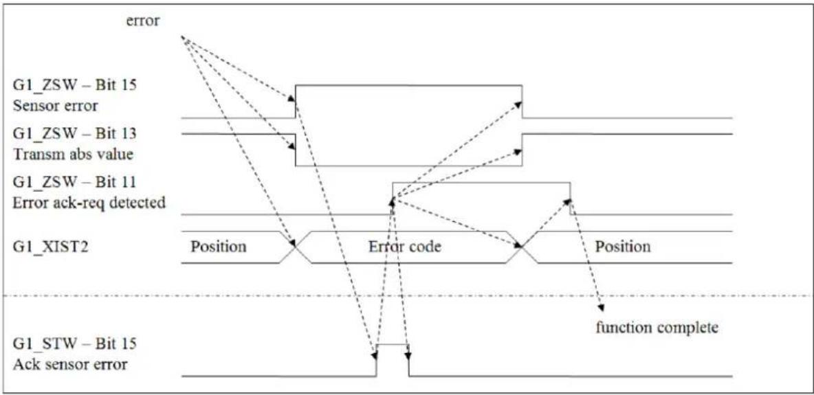
An existing error is indicated by "Sensor error" (G1_ZSW - Bit 15). "Acknowledge sensor error" (G1_STW - Bit 15) is used to acknowledge the error currently displayed in G1_XIST2. In response to the request, the encoder sets "Error acknowledge request detected" (G1_ZSW - Bit 11). The DP master can now delete the request in "Acknowledge sensor error" (G1_STW - Bit 15) again.
The function is completed when the encoder deletes "Error acknowledge request detected" (G1_ZSW - Bit 11). In the error-free case, the encoder also clears "Sensor error" (G1_ZSW - bit 15), sets "Transmit absolute value" (G1_ZSW - bit 13) and displays the position value again in G1_XIST2. See Figure 6.2.
flowchart
graph TD
    A["error"] --> B["G1_ZSW – Bit 15 Sensor error"]
    A --> C["G1_ZSW – Bit 13 Transm abs value"]
    A --> D["G1_ZSW – Bit 11 Error ack-req detected"]
    A --> E["G1_XIST2 Position"]
    E --> F["Error code"]
    F --> G["Position"]
    G --> H{function complete}
    H --> I["G1_STW – Bit 15 Ack sensor error"]
Figure 6.2: State diagram G1-XIST2 error control - error-free case
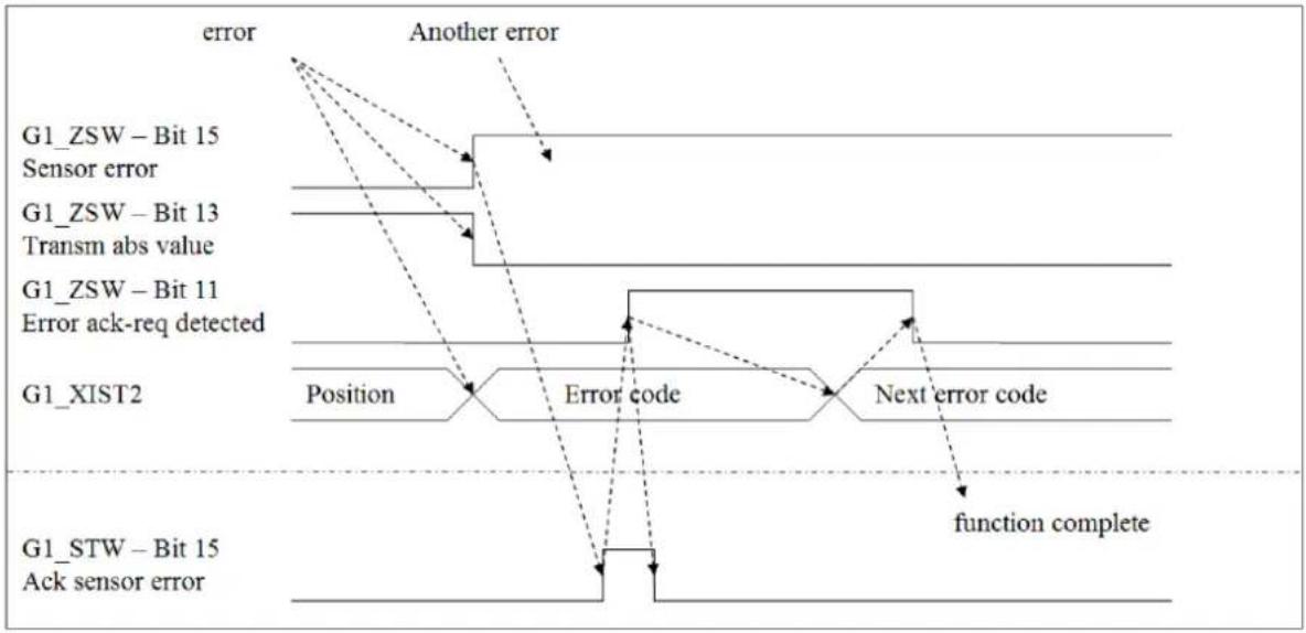
If the error persists, nothing changes. If there are other errors, only the error code changes (see Figure 6.3).
flowchart
graph TD
    A["Error"] --> B["G1_ZSW – Bit 15 Sensor error"]
    A --> C["G1_ZSW – Bit 13 Transm abs value"]
    A --> D["G1_ZSW – Bit 11 Error ack-req detected"]
    A --> E["G1_XIST2 Position"]
    E --> F["Error code"]
    F --> G["Next error code"]
    G --> H["function complete"]
    I["G1_STW – Bit 15 Ack sensor error"] --> J["End"]
Figure 6.3: State diagram G1_XIST2 error control - error case
 | An absolute position value in G1_XIST2 is indicated by "Transmit absolute value" (G1_ZSW - Bit 13).An error code in G1_XIST2 is indicated by "Sensor error" (G1_ZSW - Bit 15).If "Sensor error" and "Transmit absolute value" are 0, G1_XIST2 contains no valid value.Sensor error" and "Transmit absolute value" are never set simultaneously. |
6.4.6 G1\_XIST3
 | • This value displays the position value as a 64-bit value. |
The preset function always affects this value.
6.4.7 NIST\_A & NIST\_B

- NIST_A and NIST_B display the current speed as signed 16-bit and 32-bit values, respectively.
If the shaft rotates in the positive direction, the speed value is also positive. The speed unit can be set in the parameterization (see section 6.3.10).
6.4.8 Debug\_STW & Debug\_ZSW
See section 7.16.
6.4.9 STW2\_ENC & ZSW2\_ENC
In STW2_ENC (output data), bits 12-15 contain the "master sign of life" of the isochronous mode (see Table 6.9).
| output data | |||||||||||||||
| 15 | 14 | 13 | 12 | 11 | 10 | 9 | 8 | 7 | 6 | 5 | 4 | 3 | 2 | 1 | 0 |
| Master Vital signs | 0 | Control by PLC | 0 | 0 | 0 | 0 | 0 | 0 | 0 | 0 | 0 | 0 | |||
Table 6.9: STW2_ENC
The "slave sign of life" (input data) for IsoM is located in bits 12-15 of ZSW2_ENC (see Table 6.10).
| input data | |||||||||||||||
| 15 | 14 | 13 | 12 | 11 | 10 | 9 | 8 | 7 | 6 | 5 | 4 | 3 | 2 | 1 | 0 |
| Slave sign of life | 0 | 0 | Control requested | 0 | 0 | 0 | 0 | 0 | 0 | 0 | 0 | 0 | |||
Table 6.10: ZSW2_ENC

• See sections 7.14 and 6.9 further details.
6.4.9.1 Control by PLC/request - Control priority
An optional function for a class 4 encoder is to change the control priority to another channel. Normally the control priority of the DPM1 is via the channel of the cyclic data exchange. Via this channel, the DP master can specify via "Control by PLC" (STW2_ENC - Bit 10) whether its control words are valid and should therefore be evaluated. On the other hand, the DP slave indicates to the DP master via "Control requested" of the status word whether its control words are evaluated.
This function does not exist in compatibility mode, therefore "Control by PLC" of the control word (STW2_ENC - Bit 10) is ignored and "Control requested" of the status word (ZSW2_ENC - Bit 9) is always 0. The control words are therefore always evaluated.

- Changing the control priority to another channel is not supported by the WDGA encoder.
6.5 Diagnosis
Details to the diagnostic telegram can be found in Table 6.11.
| data block | octet | Description of the |
| standard diagnosis | 1 ... 6 | DP-V0 diagnosis. |
| Identifier related diagnosis | 7 ... 8 | Identifier-related diagnosis, where only bit 1 is used. |
| Modules status | 9 ... 13 | Module status, where only bits 2 and 3 are used. |
| Channel related diagnosis | 14 ... 16 | Channel-related diagnosis, whereby the block can only be seen in the event of an incoming error.Error codes in octet 15:5: Temperature too high9: Error16: Maximum speed exceeded22: Position error24: EEPROM error25: Test error (see section 7.16) |
| Diagnosis alarm | 17 ... 21 (coming)14 ... 18 (walking) | diagnostic interruptError codes in octet 20 (17):1: Singleturn communication disturbed2: Multiturn communication disturbed3: EEPROM communication disturbed4: Internal singleturn error5: Internal multiturn error6: CRC error in EEPROM7: Magnetic field strength too weak 8:Magnetic field strength too high9: Test error (see section 7.16) |
Table 6.11: Diagnostic telegram
6.6 I&M functions

• See also section 7.12.
6.6.1 I&M0
The I&M0 data block is the only one mandatory for all DP-V1 devices. It is the only one that cannot be changed by the user. The Table 6.12 shows the corresponding functions.
| name | data type | octet | Description of the |
| Reserved | Octet string [10] | 1 ... 10 | Always 0 |
| MANUFACTURER_ID | Unsigned 16 | 11 ... 12 | For Wachendorff Automation: 0x027B |
| ORDER_ID | Visible string [20] | 13 ... 32 | The order number of the device. Since the order number has more than 20 digits, "WDGA-MT-DP" or "WDGA-ST-DP" always stands for singleturn variants. |
| SERIAL_NUMBER | Visible string [16] | 33 ... 48 | The serial number of the encoder in ASCII code. |
| HARDWARE_VERSION | Unsigned 16 | 49 ... 50 | The revision number of the encoder in ASCII code. |
| SOFTWARE_VERSION | 1 Char, 3 Unsigned 8 | 51 ... 54 | The software version. 3 e.g: V1.0.0. The letter is supplied in ASCII code but the digits are not. |
| REVISION_COUNTER | Unsigned 16 | 55 ... 56 | This counter is incremented by one each time one of the writeable I&M data blocks is changed. |
| PROFILE_ID | Unsigned 16 | 57 ... 58 | For encoder profile 4.1: 0x3D00 |
| PROFILE_SPECIFIC_TYPE | Unsigned 16 | 56 ... 60 | Multiturn: 1 Singleturn: 0 |
| IM_VERSION | 2 Unsigned 8 | 61 ... 62 | Always 1.1 |
| IM_SUPPORTED | Unsigned 16 (bit array) | 63 ... 64 | Each bit represents a supported I&M data block. For WDGA: 0x001A |
Table 6.12: I&M0
6.6.2 I&M1
| name | data type | octet | Description of the |
| Reserved | Octet string [10] | 1 ... 10 | Always 0 |
| TAG_FUNCTION | Visible string [32] | 11 ... 42 | A description of the function or task of the device. |
| TAG_LOCATION | Visible string [22] | 43 ... 64 | Describes where to find the device. |
Table 6.13: I&M1
6.6.3 I&M2
Not supported due to a specification conflict between the Profile Guideline for I&M of the PNO and the ISO standard for Profibus that was not clarified at the time of development.
6.6.4 I&M3
| name | data type | octet | Description of the |
| Reserved | Octet string [10] | 1 ... 10 | Always 0 |
| DESCRIPTOR | Visible string [54] | 11 ... 64 | Customer-specific meaning. |
Table 6.14: I&M3
6.6.5 I&M4
| name | data type | octet | Description of the |
| Reserved | Octet string [10] | 1 ... 10 | Always 0 |
| SIGNATURE | Visible string [54] | 11 ... 64 | Customer-specific meaning.Does not have to be ASCII coded.Unused bytes should be 0. |
Table 6.15: I&M4
6.7 Acyclic parameter access
6.7.1 Basics
The acyclic parameter access of the encoder uses the "Base Mode Parameter Access - Global" function from the PROFIdrive specification and is equivalent to the function of drives or inverters with PROFIdrive. In PROFIBUS-DP, parameter access takes place via the MS1 or MS2 communication relationship, whereby the MS1 connection is optional.
As a rule, these parameters should not have to be changed by the parameterization master. Parameters are always divided into those with global or local validity.
The local parameters can only be addressed via slot 1, since they refer to the encoder module virtually plugged in there.
The global parameters refer to the complete device and can therefore also be accessed via slot 0 of the basic device.
Each parameter has a unique parameter number (PNU) and a data type. If the data type is an array, a subindex is used to address the individual fields in addition to the PNU. Here it is possible to read out several fields of the array with one query.
With character strings, the subindex is used to address the individual characters.
Thus long character strings can also be read out distributed over several queries.
For simple data types, the subindex is 0.
Multi-parameter access also allows multiple PNUs to be accessed with a single query. For this purpose, a corresponding number of parameter addresses and, in the case of a write access, the values must be transferred.

- In addition to its value, a parameter also has a structured description. However, this is not supported by the encoder.
- Since these parameters are not set automatically at every start-up, they will be lost if they are not permanently stored via P971 or P977.
Asynchronous parameter access is implemented using the DP-V1 functions DS_WRITE and DS_READ. The following Table 6.16 shows the coding.
| significance DP-V1 | significance BMPA-G | significance parameter | Size (Octets) | value | statement |
| Function_num | 1 | 0x5F0x5E | DS_WRITE DS_READ | ||
| Slot_num | 1 | 0, 1 | Encoder unit | ||
| index | 1 | 0x2F | Process Data ASE | ||
| length | 1 | X | Length of data | ||
| data Max 238 | ReqRef | 1 | X | Slave mirrors value sent from master | |
| ReqID | 1 | 0x010x020x810x82 | requestchangeNeg req resNeg chg res | ||
| EO | 1 | 01 | GlobalGlobal + Local | ||
| Num Param | 1 | 1 ... 39 | Number of parameters in multi parameter access | ||
| 1 stParam Address | Attr | 1 | 0x100x200x30 | valuedescriptiontext | |
| Num Elem | 1 | 0, 11 ... 234 | valueArray + string | ||
| PNU | 2 | 1 ... 65535 | paramnumber | ||
| subindex | 2 | 0 ... 65535 | index of array | ||
| Nth Param Address | ... | (N - 1) ... 6 | |||
| 1 stParam Value | size | 1 | X | zerodatatypeerror | |
| Num values | 1 | X | Number of values from array (equal to Num Elem) | ||
| Mth value | X | X | |||
| 1 stvalue | (M - 1) · M | ||||
| Nth Param Value | ... | ||||
| X | Arithmetic sum from DA to DU (only lowest byte) | ||||
| 0x16 | End delimiter |
Table 6.16: Coding of asynchronous parameter requests
The data type of a parameter value is encoded in the octet "Format". The following Table 6.17 shows the possible values.
| size | data type | Description of the |
| 0x04 | Integer 32 | Signed 32-bit integer. |
| 0x06 | Unsigned 16 | Unsigned 16-bit integer |
| 0x07 | Unsigned 32 | Unsigned 32-bit integer |
| 0x09 | VisibleString | ASCII encoded characters in an array.Unused characters have the value 0x20, this corresponds to a blank character. |
| 0x0A | OctetString | Array of bytes |
| 0x37 | Integer 64 | Signed 64-bit integer |
| 0x40 | zero | The value has a size of 0 bytes and no meaning. Used to skip the error-free accesses in case of a negative response to a multi-parameter access, so that the error message can be assigned to the correct parameter. |
| 0x44 | error | The value returned is not the value of the parameter, but an error message. |
Table 6.17: Coding - Format
The possible error messages that can be sent instead of the parameter value can be found in the Table 6.18.
| code | name | significance |
| 0x0000 | InvalidParamNum | Invalid PNU: the requested PNU is not implemented. |
| 0x0001 | ReadOnly | An attempt has been made to write to a PNU that can only be read. |
| 0x0002 | ValueRangeExceeded | The written value is not within the valid value range. |
| 0x0004 | NoArray | A subindex greater than 1 was specified, although the parameter is not an array. |
| 0x0005 | IncorrectDatatype | The data type of the value to be written does not match the data type of parameter |
| 0x0006 | SetToZeroOnly | Only the value "0" may be written to the parameter. |
| 0x0007 | DescriptionReadOnly | The parameter description can only be read |
| 0x0009 | DescriptionNotAvailable | The parameter description cannot be read. |
| 0x000F | Text ArrayNotAvailable | The text description of the parameter cannot be read. |
| 0x0011 | WrongState | Parameter access cannot be carried out in the current state of the encoder. If, for example, a 64-bit preset value was set, it cannot be read out via the 32-bit parameter. |
| 0x0015 | ResponseTooLong | The answer does not fit into the remaining free space in the telegram. |
| 0x0016 | InvalidParamAddr | The parameter address in the request telegram is invalid. The Attr field must have the value 0x10. |
| 0x0018 | ValueNumbersInconsistent | The number of transferred values during write access must match the number of elements in the parameter address. If the parameter is not an array, the number of transmitted values must be 1. |
| 0x0019 | InvalidEO | Access to local parameters only possible via slot 1. The field EO in the request telegram must be one. |
Table 6.18: Error codes
6.7.2 Read parameters
Figure 6.4 shows an example of reading the first two elements of PNU 980 (see Table 6.27). The printed octets highlighted are the user data of the DS_READ or DS_WRITE service.

Table 6.19 shows the read request of the DP master. The meaning of the highlighted printed octets from Figure 6.4 is described here.
| significance BMPA-G | significance texture | Size | value | statement |
| ReqRef | 1 | 1 | No meaning. Master specifies any value | |
| ReqID | 1 | 0x01 | read request | |
| EO | 1 | 1 | Access to global and local data | |
| Num Param | 1 | 1 | Read a parameter | |
| Param Address | Attr | 1 | 0x10 | Read the value of the parameter |
| Num Elem | 1 | 2 | Read two elements of the array | |
| PNU | 2 | 03D4h = 980d | The parameter number | |
| subindex | 1 | 0 | The start index of the elements to be read out |
Table 6.19: DS_Write - Master
Table 6.20 shows the response of the DP slave. The meaning of the highlighted printed octets from Figure 6.4 is described here.
| significance BMPA-G | significance texture | Size | value | statement |
| ReqRef | 1 | 1 | No meaning. Slave mirrors the value from the request | |
| ReqID | 1 | 0x01 | read request | |
| EO | 1 | 1 | Access to global and local data | |
| Num Param | 1 | 1 | Read a parameter | |
| 1st Param Value | size | 1 | 6 | Unsigned integer 16 bits |
| Num values | 1 | 2 | Number of the following values | |
| 1st value | 2 | 0x0396 | Subindex 0: 918 | |
| 2nd value | 2 | 0x0397 | Subindex 1: 919 |
Table 6.20: DS_Read - Slave
6.7.3 Write parameters
Figure 6.5 shows an example of writing a new preset value. The printed octets highlighted are the user data of the DS_READ or DS_WRITE service.
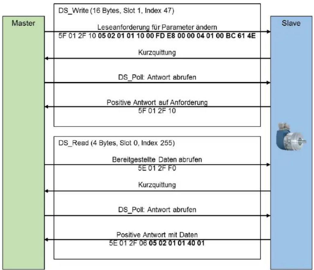
flowchart
graph TD
    A["Master"] --> B["DS_Write (16 Bytes, Slot 1, Index 47)"]
    B --> C["Slave"]
    A <--> D["DS_Poll: Antwort abrufen"]
    D --> C
    A <--> E["Positive Antwort auf Anforderung"]
    E --> C
    A <--> F["DS_Read (4 Bytes, Slot 0, Index 255)"]
    F --> C
    A <--> G["Kurzquittung"]
    G --> C
    A <--> H["DS_Poll: Antwort abrufen"]
    H --> C
    A <--> I["Positive Antwort mit Daten"]
    I --> C
Figure 6.5: Setting the preset value to 12345678d via P65000
Table 6.21 shows the read request of the DP master. The meaning of the highlighted printed octets from Figure 6.5 is described here.
| significance BMPA-G | significance texture | Size | value | statement |
| ReqRef | 1 | 5 | No meaning. Master specifies any value | |
| ReqID | 1 | 0x02 | write request | |
| EO | 1 | 1 | Access to global and local data | |
| Num Param | 1 | 1 | Read a parameter | |
| Param Address | Attr | 1 | 0x10 | Read the value of the parameter |
| Num Elem | 1 | 0 | P65000 is not an array | |
| PNU | 2 | FDE8h = 65000d | The parameter number | |
| subindex | 2 | 0 | The start index of the elements to be read out | |
| 1st Param Value | size | 1 | 4 | Signed integer 32 bits |
| Num values | 1 | 1 | Number of the following values | |
| 1st value | 2 | 00BC614Eh = 12345678d | preset value |
Table 6.21: DS_Write - Master
Table 6.22 shows the response of the DP slave. The meaning of the highlighted printed octets from Figure 6.5 is described here.
| significance BMPA-G | significance texture | Size | value | statement |
| ReqRef | 1 | 5 | No meaning. Slave mirrors the value from the request | |
| ReqID | 1 | 0x02 | write request | |
| EO | 1 | 1 | Access to global and local data | |
| Num Param | 1 | 1 | Read a parameter | |
| 1st Param Value | size | 1 | 40 | Zero: No values follow after the number |
| Num values | 1 | 01 | Number of written values |
Table 6.22: DS_Read - Slave
6.7.4 Error handling
Assuming the total measuring range of the encoder would be less than 12345678d. In this case, the encoder would respond to the request of the last example 6.7.3 with an error message. The preset value must be smaller than TMR.
The requirement is identical to the example from 6.7.3 following Table 6.23 response of the encoder.
| significance BMPA-G | significance texture | Size | value | statement |
| ReqRef | 1 | 5 | No meaning. Slave mirrors the value from the request | |
| ReqID | 1 | 0x82 | Write request not successful | |
| EO | 1 | 1 | Access to global and local data | |
| Num Param | 1 | 1 | Read a parameter | |
| 1st Param Value | size | 1 | 44 | The following is an error code |
| Num values | 1 | 01 | Number of values | |
| 1st value | 2 | 0x0002 | Error code: Value outside the valid range. |
Table 6.23: Error handling - Slave
6.7.5 PROFIdrive parameters
The PROFIdrive parameters can be found in Table 6.24 to Table 6.27.
| PNU | significance | type | R/W | L/G | subindex | bit | function | Description of the |
| 918 | Node address | Unsigned 16 | R | G | The PROFIBUS slave address of the encoder | |||
| 919 | Encoder Unit system number | Visible String [16] | R | L | Always "WDGA-MT-DP". | |||
| 922 | Telegram selection | Unsigned 16 | R | L | Number of the configured I/O telegram | |||
| 925 | Max. Master Sign-Of-Life failures | Unsigned 16 | RW | L | The limit of the error counter is set to ten times this value. | |||
| 964 | Encoder Unit identification | Unsigned 16 | R | G | 0 | manufacturer | PNO manufacturer ID as I&M: Always 0x027B | |
| 1 | Encoder Unit Type | Always 0 | ||||||
| 2 | Software version | e.g.0x0102 for version 1.2 | ||||||
| 3 | Firmware date (year) | Year of firmware creation: yyyy | ||||||
| 4 | Firmware date (day/month) | Day and month of firmware creation: ddmm | ||||||
| 5 | Number of Encoder Objects | Number of EO within the EU: Always 1 | ||||||
| 965 | Profile identification number | Octet String [1] | R | G | Byte 1: 61d (encoder profile)Byte 2: Version: 41d (Compatibility mode: 31d) | |||
| 971 | Transfer to NVM | Unsigned 16 | RW | G | To start saving write a 1. The value is set to 0 as soon as the saving is completed. The values of P65000, P65002 and P925 are stored. | |||
| 972 | Device reset | Unsigned 16 | RW | G | Default value: 0. Writing 2 has no effect.Write 1 executes a device reset, whereby the value jumps back to 0. | |||
| 974 | base fashion parameter access service identification | Unsigned 16 | R | G | 0 | Max block length | Maximum length of the parameter request: 240 bytes | |
| 1 | Max number of parameter requests per multi-parameter request | Number of possible parameter accesses per parameter request: 39 | ||||||
| 3 | Max latency per request | 0: not specifiedX: Multiply by 10ms to obtain the maximum processing time in the worst case, without line delay on the bus. Takes into account the case of multi-parameter access. | ||||||
| 975 | Encoder object identification | Unsigned 16 | R | L | 0 | Manufacturer | PNO manufacturer ID like I&M: always 0x027B | |
| 1 | EO type | Always 0 | ||||||
| 2 | Software version | e.g.: 0x0102 for version 1.2 | ||||||
| 3 | Firmware date (year) | Year of firmware creation: 2014d for the year 2014 | ||||||
| 4 | Firmware date (day/month) | Day and month of firmware creation: 0x0a09 for September 10th | ||||||
| 5 | EO type class | Always 5: Encoder Interface | ||||||
| 6 | EO sub class | Always 0xC000 Encoder Class 3 and 4 supported | ||||||
| 0...5 | Always 0 | |||||||
| 6...13 | Always 0 | |||||||
| 14 | Always 1 | |||||||
| 15 | Always 1 | |||||||
| 7 | EO-ID | The number of the encoder object to which the parameter request was addressed. Always 1 | ||||||
| 977 | Transfer to NVM | Unsigned 16 | RW | G | To start saving write a 1. The value is set to 0 as soon as the saving is completed. The values of P65000, P65002 and P925 are stored. | |||
| 979 | Sensor format | Unsigned 32 | R | L | 0 | header | Describes the structure of the parameter. Always 0x00005111 | |
| 0...3 | version | This version is incremented when compatible changes are made to the structure. Always 1 | ||||||
| 4...7 | version | This version is incremented if the structure is changed in an incompatible way. Always 1 | ||||||
| 979 | Sensor format | Unsigned 32 | R | L | 0 | 8...11 | Number of sensors | Number of sensors described: Always 1 |
| 12...15 | Number of indices per sensor | Number of subindices per sensor: Always 5 | ||||||
| 16...31 | Reserved | Always 0 | ||||||
| 1 | Sensor type | |||||||
| 0 | Linear sensor | Always 0: rotary sensor (rotary encoder) | ||||||
| 1 | Absolute sensor | Always 1: The Ab-solute value is available immediately. | ||||||
| 2 | 64-bit position | Always 1: 64-bit position information is available | ||||||
| 3...30 | Reserved | Always 0 | ||||||
| 31 | Data valid | 1: Data of the sensors are valid | ||||||
| 2 | Sensor resolution | Current resolution in steps per revolution | ||||||
| 3 | Shift factor G1_XIST1 | Always 0 The position value in G1_XIST1 is always aligned to the right. | ||||||
| 4 | Shift factor G1_XIST2 | Always 0. The position value in G1_XIST2 is always aligned to the right. | ||||||
| 5 | Determinable revo-lutions | Number of distinguishable revolutions of the rotary encoder | ||||||
| 980 | Number List of defined parameters | R | L | 0...18 | List of all available parameters. Each element contains a PNU. The end of the list contains the 0 |
Table 6.24: Telegram Structure - Part 1
Table 6.25: Telegram Structure - Part 2
Table 6.26: Telegram Structure - Part 3
Table 6.27: Telegram Structure - Part 4
6.7.6 Manufacturer specific parameters
The manufacturer-specific parameters can be found in Table 6.28.
| PNU | significance | R/W | L/G | Description of the |
| 1000 | Test 1 | RW | G | For production purposes only, not described |
| 1001 | Test 2 | RW | G | For production purposes only, not described |
Table 6.28: Manufacturer-specific parameters
6.7.7 Encoder-specific parameters
The encoder-specific parameters can be found in Table 6.29 to Table 6.31.
| PNU | significance | type | R/W | L/G | sub index | bit | function | Description of the |
| 65000 | Preset value | Integer 32 | RW | G | The preset function of the cyclic data exchange sets the position value to this value. With an absolute preset, this value is considered unsigned. | |||
| 65001 | operating parameters | Array [12] Integer 32 | RO | G | 0 | header | Describes the structure of the parameter. Always 0x000C0101. | |
| 0...7 | version | This version is incremented when compatible changes are made to the structure. | ||||||
| 8...15 | version | This version is incremented if the structure is changed in an incompatible way. Always one. | ||||||
| 16...23 | Number of indices | Number of existing subindexes. Always: 12 | ||||||
| 24...31 | Reserved | Always 0 | ||||||
| 1 | 0 | code sequence | Shows whether class 4 functions have been activated. | |||||
| 1 | Class 4 function | Shows whether class 4 functions have been activated. | ||||||
| 2 | G1_XIST1 preset control | Shows whether the preset function affects the position value G1_XIST1. | ||||||
| 3 | Scaling function control | Shows whether the full diagnosis is output. | ||||||
| 65001 | operating parameters | Array [12] Integer 32 | RO | G | 1 | 4 | Alarm channel control | Shows whether the full diagnosis is output. |
| 5 | Compatibility mode | Shows whether the compatibility mode is active. | ||||||
| 6, 7 | Reserved | Always 0 | ||||||
| 2 | sloth | Shows errors that can affect the position value. | ||||||
| 0 | Position error | The position value is not correct | ||||||
| 1 | undervoltage | Always 0 | ||||||
| 2 | overvoltage | Always 0 | ||||||
| 3 | shortcircuit | Always 0 | ||||||
| 4 | Commissioning diagnostic | Always 0 | ||||||
| 5 | Memory error | The EEPROM does not work. | ||||||
| 6...31 | Reserved | Always 0 | ||||||
| 3 | Supported faults | Occupancy like Faults. Always 0x00000021 | ||||||
| 4 | warnings | Warnings have no effect on the position value | ||||||
| 0 | Frequency exceeded | Maximum speed is exceeded | ||||||
| 1 | overtemperature | Temperature too high | ||||||
| 2 | Light control reserve | Always 0 | ||||||
| 3 | CPU Watchdog status | Always 0 | ||||||
| 4 | Operating time limit warning | Always 0 | ||||||
| 5 | Battery voltage low | Always 0 | ||||||
| 6 | Reference point not reached | Always 0 | ||||||
| 7...31 | Reserved | Always 0 | ||||||
| 5 | Supported warnings | Assignment of warnings Always: 0x00000003 | ||||||
| 6 | Encoder profile version | Always 0x0041 | ||||||
| 65001 | operating parameters | Array [12] Integer 32 | RO | G | 7 | operating time | Operating hours counter in 0.1 hour intervals.P65001.6: independent of compatibility mode | |
| 8 | Offset value | The offset calculated by the preset function. | ||||||
| 9 | Measuring unit per revolution | The parameterized resolution | ||||||
| 10 | Total measuring range | The parameterized total measuring range | ||||||
| 11 | Speed measuring unit | The parameterized unit of the velocity value | ||||||
| 65002 | Preset value 64-bit | Integer 64 | RW | G | The 64-bit version of the preset value | |||
| 65003 | Operating status 64 bit | Array [] Integer 64 | RO | G | 0 | 0 | header | Always 0x40101 |
| 1 | Offset value 64 bit | The 64-bit ion of the offset value | ||||||
| 2 | Measuring unit per revolution 64 bit | The 64-bit version of the parameterized resolution | ||||||
| 3 | Total measuring range 64 bit | The 64-bit version of the parameterized total measuring range |
Table 6.29: Encoder-specific parameters - Part 1
Table 6.30: Encoder-specific parameters - Part 2
Table 6.31: Encoder-specific parameters - Part 3
6.8 Slave cross traffic - DxB
Slave cross-traffic is supported by the encoder as a publisher. See chapter Profibus 7.13.
6.9 Isochronous mode - IsoM
6.9.1 State machine
In order to start the isochronous mode completely, the encoder runs through further states, which only affect the isochronous mode, in addition to the normal PROFIBUS-DP states. The sequence for WDGA encoders is specified by the PROFIdrive specification. For other DP slaves the sequence may differ.

flowchart
graph TD
    A["Offline"] --> B["Preparation Phase 1"]
    B --> C["Preparation Phase 2"]
    C --> D["Synchronisation"]
    D --> E["Operation"]
    F["Offline"] --> G["Parameterization"]
    G --> H["Configuration"]
    H --> I["Data Exchange"]
    I --> J["Offline"]
    style A fill:#f9f,stroke:#333
    style F fill:#f9f,stroke:#333
    style J fill:#f9f,stroke:#333
    subgraph Isochroner Modus
        B
        C
        D
        E
    end
    subgraph Profibus-DP
        G
        H
        I
    end
Figure 6.6: Isochronous State Machine and DP State Machine
6.9.2 Offline
The "Offline" state corresponds to the PROFIBUS-DP state and indicates the case in which the encoder is switched off.
6.9.3 Preparation Phase 1
The "Preparation Phase 1" state includes the parameterization and configuration from PROFIBUSDP. The encoder then switches to cyclic data exchange with the DP master and simultaneously to the "Preparation Phase 2" state.
6.9.4 Preparation Phase 2
In the "Preparation Phase 2" state, the encoder synchronizes its internal clock with the clock beat telegram of the DP master. After that it is synchronous with the DP cycle and switches to the synchronisation of the life sign counter.
6.9.5 Synchronisation
The "Master Sign of Life" is located in STW2_ENC (see section 6.4.9). The "Slave Sign of Life" is activated as soon as the "Master Sign of Life" is incremented by one. I.e. in an isochronous application, the control program must automatically begin to increase the sign of life after initialization. The valid value range is from 1 to 15. The value 0 indicates an invalid sign of life. Incrementing a sign of life with the value 15 therefore leads to the value 1.
Figure 7.10 shows the synchronization process. When the system is started, the DP master usually requires more time than the DP slaves. The DP slaves first initialize themselves and then wait for parameterization and configuration to switch to cyclic data exchange. As soon as the cyclic data exchange begins, they synchronize with the clock beat telegram. Afterwards, an incrementation of the "master sign of life" is waited for. Since each DP slave was informed during parameterization how many DP cycles per DP master cycle are run through, it is now clear when the "master sign of life" has to change again and when the new "slave sign of life" has to be transmitted to the DP master.
The DP slaves permanently monitor the synchronization with the clock beat telegram on the bus. If the DP slave detects that it is no longer running synchronously, this is indicated by an error message in G1_XIST2 and a reset of the "slave sign of life" to 0. After the error has been acknowledged with bit x in STWx, the DP slave tries to synchronize again. In order for the synchronization of the DP slaves to function reliably, the control software must process and acknowledge any error messages that may occur.
6.9.6 Surgery
In the "Operation" state, the DP slave is synchronous with the DP master application cycle. The DP master can use the input data for control tasks and set them in relation to the input data of other synchronous DP slaves.
At the beginning of each DP master cycle, the encoder checks the "master sign of life". If it was not incremented correctly, an internal error counter is incremented by 10. If a correct "master sign of life" is received, however, it is reduced by one. If the error counter exceeds the permissible upper limit, the encoder switches back to the "synchronization state", reports the error via G1_XIST2 and sets the "slave sign of life" to 0. As soon as the error has been acknowledged, synchronization is carried out again and the encoder returns to the "operation state".
The permissible upper limit of the error counter can be set in compatibility mode via parameterization. Otherwise the acyclic parameter P925 must be used. The upper limit is calculated from the parameterized value times ten. It is quite possible that with a value of 3 allowed life sign errors, even more life sign errors will not reset the "slave life sign" if the error counter has been reduced again in the meantime by correct "master life signs".
7 PROFIBUS
7.1 General information
PROFIBUS was developed in 1987 by various companies and research institutes. PROFIBUS has been the world's leading fieldbus in the automation of plants and machines since 1989. PROFIBUS is characterized in particular by its wide range of applications. Application-specific requirements are implemented in corresponding application protocols.
Communication can be classified as follows in the ISO-OSI model (ISO standard 7498). The relevant layers for PROFIBUS are the first layer (Physical Layer - Layer 1), the second layer (Data Link Layer - Layer 2) and the seventh layer (Application Layer - Layer 7). Table 7.1 shows the ISO-OSI model with the PROFIBUS protocols.
| ISO-OSI layer | PROFIBUS | Description of the | |
| Layer 7application layer | PROFIBUS DP(DP-V0, DP-V1, DP-V2) | communication protocols | |
| Layer 3 - 6 | |||
| Layer 2Data Link Layer | FDL (Fieldbus Data Link) | FDL: Data transmission- Services for data transmission- FMA: Management Services- MAC: Medium access(master-slave principle,Token Passing Principle) | |
| Layer 1Physical Layer | EIA-485(also: RS485) | Optical | physical realization of the bit transmission:- UART coding |
Table 7.1: ISO-OSI Model - PROFIBUS-DP
PROFIBUS is available in three different versions:
• PROFIBUS-FMS (Fieldbus Message Specification)
• PROFIBUS-DP (Distributed Peripherals)
• PROFIBUS-PA (Process Automation)
Historically, PROFIBUS-FMS was the first PROFIBUS to be replaced by PROFIBUS-DP due to its complexity and low transmission efficiency. PROFIBUSFMS is no longer part of IEC61158. PROFIBUS-DP is the most widely used PROFIBUS and covers about 90% of the market share. In IEC61158-2, PROFIBUS-DP and PROFIBUS-PA are standardized.
PROFIBUS-DP is primarily designed for fast data exchange at the actuator/sensor level. It is mainly used in production automation.
PROFIBUS-PA is characterized by intrinsic safety and remote supply of bus stations. It is therefore mainly used in potentially explosive atmospheres. The field of application is process automation.
The user organization is the "Profibus Nutzerorganisation e.V.". (PNO)" and the international umbrella organisation is "Profibus & Profinet International (PI)".

- The manual refers exclusively to PROFIBUS-DP.
7.2 Attendee
PROFIBUS distinguishes between different PROFIBUS stations (often also called stations) (see Table 7.2).
On the one hand there are the masters and on the other hand the slaves. The masters (also called active participants) determine the data traffic in the PROFIBUS bus. The slaves (also called passive participants) are peripheral devices, such as a rotary encoder. You may acknowledge received messages or transmit messages at the request of a master. Details on the bus access procedure can be found in section 7.4.2.
Since PROFIBUS supports different versions (FMS, DP or PA), the corresponding abbreviation is often prefixed to the master or slave, such as DP master and DP slave.
| attendee | class | Short | Description of the | communication relation |
| DP master | 1 | DPM1 | - PLC (en: PLC)cyclic data traffic and acyclic data traffic | MS0 (DP slave: DP-V0)MS1 (DP slave: DP-V1)MM (DPM2, rather rare) |
| DP master | 2 | DPM2 | - Configuration and diagnostic device- Diagnosis and parameterization of the DP slave- Engineering station (mostly PC-based system)only acyclic data traffic | MS2 (DP slave: DP-V1)MM (DPM1, rather rare) |
Table 7.2: Master variants in the DP system

- The rotary encoder is a DP slave.
- Communication relationships see section 7.6
7.3 Physical Layer - Layer 1
7.3.1 Bus line
The PROFIBUS cables are shielded and twisted two-wire copper cables. There are different types of design, which can differ in the structure of the cores (flexible/rigid) and/or in the sheathing.
The PROFIBUS standard cables usually have a purple outer sheath. The signal line A, is usually green, and the signal line B, is usually red isolated.

- PROFIBUS cables can also be found on our website under the following link:
www.wachendorff-automation.com
In Table 7.3 you find an overview of the different execution types. Hybrid cables are also available for all version types. These additionally contain a variable number of copper wires for the supply.
| PROFIBUS-DP version types | typ. Coat colour | Use of the |
| standard cable | violet | Indoor and/or outdoor area |
| Cable with PE-jacket | black | Food and luxury food industry |
| underground pipeline (additional outer sheath) | black | direct laying in the ground |
| Trailing cable / for garland suspension(Cable type A often not fulfilled, no maximum network expansion possible) | turquoise | Use with moving machine partsSpecial cables are available for drag chains, garland suspension or torsion movements. |
Table 7.3: PROFIBUS cables - version types

- Make sure that you use correct PROFIBUS cables according to your application.
The specification of the bus cable is defined in IEC 61158. The electrical properties (line parameters) of the bus line for line type A are shown in Table 7.4.
| parameter | limit |
| characteristic impedance [Ω] | 135 - 165 (from 3 - 20 MHz) |
| capacity flooring [pF/m] | ≤ 30 |
| loop resistance [Ω/km] | ≤ 110 |
| wire diameter [mm] | >0,64 |
| wire cross-section [mm2] | >0,34 |
Table 7.4: Line parameters - Line type A

- Only use cable type A
Further properties that may be relevant to your application can be found in Table 7.5.
| demand | property |
| mechanical | bending radius |
| mechanical | bending frequency |
| mechanical | tensile strength |
| chemically | UV resistance |
| chemically | absence of silicone |
| chemically | Resistance to mineral oils and greases |
| chemically | Permissible temperatures |
| reaction to fire | absence of halogen |
| reaction to fire | flame retardancy |
| reaction to fire | smoke density |
Table 7.5: Possible requirements for the bus line
7.3.2 Transmission speed
A total of 126 participants can participate in a PROFIBUS system. When the maximum number of stations is reached, the PROFIBUS is divided into individual segments. The segments can be coupled to the PROFIBUS via repeaters. 32 subscribers can be connected per segment (the repeater is also a subscriber).
Theoretically, the maximum transmission speed depends on the longest segment. However, there are further possibilities to increase the transmission speed with the use of additional repeaters.
If the line parameters of line type A are complied with, the transmission speeds apply to the maximum segments (see Table 7.6).
| Transmission speed [kBit/s] | max. segment length [m] |
| 9,6 | 1200 |
| 19,2 | 1200 |
| 45,45 | 1200 |
| 93,75 | 1200 |
| 187,5 | 1000 |
| 500 | 400 |
| 1500 | 200 |
| 3000 | 100 |
| 6000 | 100 |
| 12000 | 100 |
Table 7.6: Transmission speeds - Line type A

- At transmission rates > 1500kbit=s no stubs are allowed.
- For transmission rates < 1500kbit=s different spur line lengths are permissible depending on the transmission rate (in case you use spur lines, please inform yourself about this).
- No termination is carried out for stub lines.
7.3.3 Termination
Termination prevents reflections during data transmission. In addition, it ensures a defined rest potential on the data line if no subscribers are active. An active termination must be present at the beginning and end of an RS-485 segment. The active scheduling is shown in Figure 7.1.

- Please refer to section 4.4.3 or 4.5.2 termination for the WDGA.
- 5 V DP and GND DP are galvanically isolated from the supply voltage.
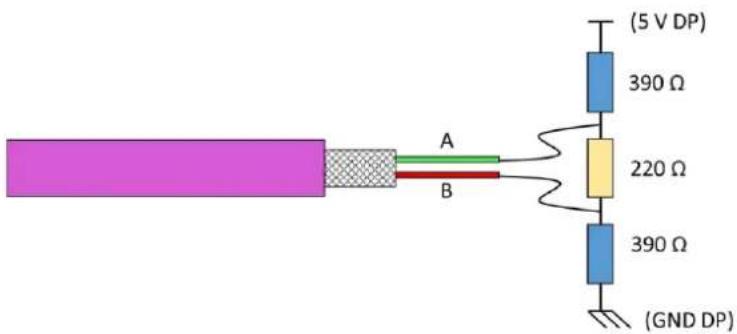
Figure 7.1: Termination - Line type A

- Incorrect scheduling leads to communication problems
7.4 Data Link Layer - Layer 2
7.4.1 General information
The "Data Link Layer" generally describes the bus access procedure, data backup and transmission services. The "Data Link Layer" is called "Field Data Link" (FDL) on PROFIBUS.
7.4.2 Bus access method
With PROFIBUS, the bus access procedure is carried out via the token passing procedure (master-master procedure) or via a combination with the master-slave procedure.
In the token-pasing procedure, the bus access authorization (token) is passed from one DP master to the next within a specified time. The token message contains the send authorization for the corresponding DP master. The token ring is the connection between different DP masters (see Figure 7.2). The token message is passed on to each other in a given order.
In the master-slave procedure, the request of a DP master authorizes the DP slave to send to the bus for a certain time. DP slaves are only allowed to respond to DP master requests. The DP master with the send authorization can send messages to the DP slaves.
With the token-passing and the master-slave procedure it is possible to realize three different system configurations. A pure master-slave system (MS system), a pure master-master system (MM system) or a hybrid access method from the MS and MM systems.
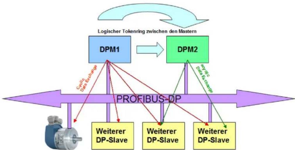
flowchart
graph TD
    A["Logischer Tokenring zwischen den Mastern"] --> B["DPM1"]
    B --> C["DPM2"]
    C --> D["PROFIBUS-DP"]
    D --> E["Weiterer DP-Slave"]
    D --> F["Weiterer DP-Slave"]
    D --> G["Weiterer DP-Slave"]
    B --> H["Cyclic Data Exchange"]
    C --> I["Key of: Data Exchange"]
    D --> J["Data Exchange"]
Figure 7.2: PROFIBUS-DP station
7.5 Application Layer - Layer 7
7.5.1 Communication protocol - DP-V0, DP-V1, DP-V2
Historically, there are different DP communication protocols. The original version is DP-V0 (PROFIBUS DP Version 0, 1991: DIN 19245, later:
EN 50170). This was extended in DP-V1 (PROFIBUS DP Version 1) and defined in a new standard (IEC 61158). There are further additions to this version (PROFIBUS DP Version 2), which have been adopted into IEC 61158 since 2002.
In practice, the term DP-V2 is often used in this context, although these are merely additions to DP-V1. The main functions of the individual versions are shown in Figure 7.3.
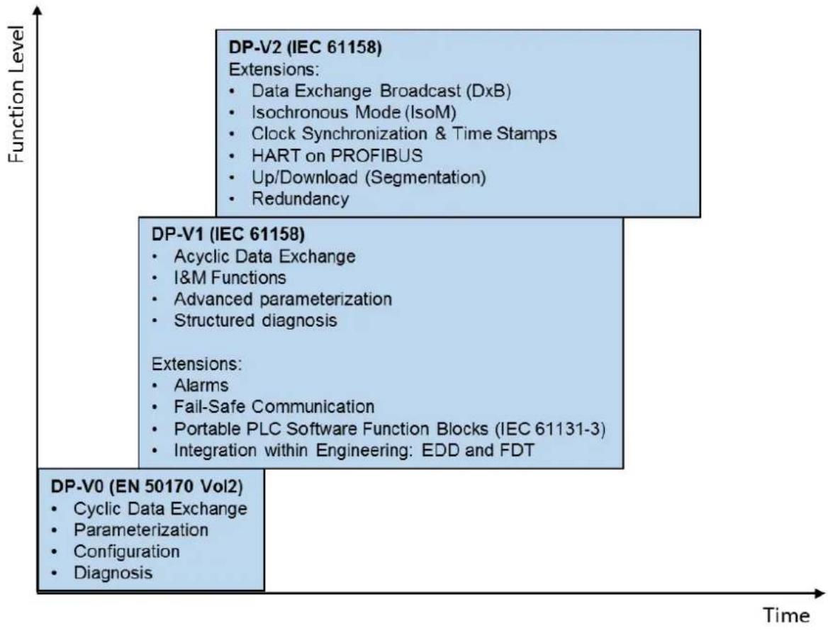
flowchart
graph TD
    A["DP-V0 (EN 50170 Vol2)"] --> B["DC"]
    B --> C["DC"]
    C --> D["DC"]
    D --> E["DC"]
    E --> F["Time"]

    subgraph A
        G["DP-V2 (IEC 61158)"]
        H["Extensions"]
        I["Data Exchange Broadcast (DxB)"]
        J["Isochronous Mode (IsoM)"]
        K["Clock Synchronization & Time Stamps"]
        L["HART on PROFIBUS"]
        M["Up/Download (Segmentation)"]
        N["Redundancy"]
    end

    subgraph B
        O["DP-V1 (IEC 61158)"]
        P["Acyclic Data Exchange"]
        Q["I&M Functions"]
        R["Advanced parameterization"]
        S["Structured diagnosis"]
    end

    subgraph C
        T["Extensions"]
        U["Alarms"]
        V["Fail-Safe Communication"]
        W["Portable PLC Software Function Blocks (IEC 61131-3)"]
        X["Integration within Engineering: EDD and FDT"]
    end

    subgraph D
        Y["DP-V0 (EN 50170 Vol2)"]
        Z["Cyclic Data Exchange"]
        AA["Parameterization"]
        AB["Configuration"]
        AC["Diagnosis"]
    end
Figure 7.3: Power levels PROFIBUS-DP
The power level DP-V0 provides the basic functions of the communication protocol. The "cyclic data exchange" of the process data is possible between DP master and DP slave. Parameterization, configuration and various diagnostic functions are also available.
DP-V1 is the addition to DP-V0. In addition, an "acyclic data exchange" between DP master and DP slave is possible. This enables parameterization, diagnosis, operation, monitoring and alarm handling of the DP slaves in parallel with cyclic user data traffic.
The I&M functions are higher services using the acyclic communication channels (MS1 and MS2). In this way, the manufacturer and the serial number can be retrieved in a uniform format. These services originally belonged to the DP V2 service level. Today, however, it is necessary that these services are supported by every new DP-V1 subscriber. Other acyclic services depend on the device profile.
DP-V2 is a further addition to the functions of DP-V0 and DP-V1. The extensions include "Slave Cross Traffic (DxB)" and "Isochronous Mode (IsoM)". The "slave cross traffic" enables direct data exchange between the DP slaves. This is only possible if this function is also supported by the DP master. The "Isochronous Mode" enables the synchronization of the acquired input and output values with the master clock. Thus the process data of the plant have the same age across slaves. This is mainly required for servo drives. Further functions, such as time guidance, can be available.
7.6 Communication relationships
There are various communication relationships between the participants (see Figure 7.4). A distinction is made between MS0, MS1 and MS2 communication relationships.
Depending on the communication relationship, different services are available (see sections 7.6.1, 7.6.2 and 7.6.3).
- MS0: Cyclic data transmission between a DPM1 and a DP slave using the DP-V0 protocol.
- MS1: Acyclic data transmission between a DPM1 and a DP slave using the DP-V1 protocol.
- MS2: Acyclic data transmission between a DPM2 and a DP slave using the DP-V1 protocol.
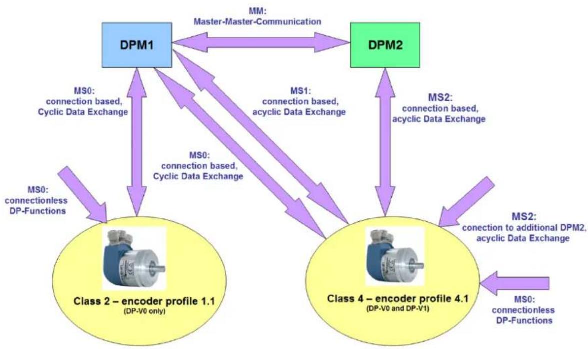
flowchart
graph TD
    A["DPM1"] -->|MS0: connection based, Cyclic Data Exchange| B["Class 2 – encoder profile 1.1 (DP-V0 only)"]
    A -->|MS0: connectionless DP-Functions| C["Class 2 – encoder profile 1.1 (DP-V0 only)"]
    D["DPM2"] -->|MS1: connection based, acyclic Data Exchange| E["Class 4 – encoder profile 4.1 (DP-V0 and DP-V1)"]
    D -->|MS2: connection based, acyclic Data Exchange| F["Class 4 – encoder profile 4.1 (DP-V0 and DP-V1)"]
    G["MM: Master-Master-Communication"] <--> A
    H["MS0: connectionless DP-Functions"] --> A
    I["MS2: connection to additional DPM2, acyclic Data Exchange"] --> F
Figure 7.4: Communication relationships
7.6.1 MS0 communication relationship
The telegrams for the MS0 communication relationship are coded by the corresponding SAPs (Service Access Points). The following SAPs are used in the MS0 communication relationship (see Table 7.7).
| SAP from DP slave | duty | function | DU from master to slave | DU from slave to master |
| default | SRD | Data_Exchange | output data | input data |
| 55 (0x37) | SRD | Set_Slave_Adr | Address | SC |
| 56 (0x38) | SRD | Rd_Inp | Empty | input data |
| 57 (0x39) | SRD | Rd_Outp | Empty | output data |
| 58 (0x3A) | SRD | Global_Control | control | - |
| 59 (0x3B) | SRD | Get_Cfg | Empty | configuration |
| 60 (0x3C) | SRD | Slave_Diag | Empty | diagnosis |
| 61 (0x3D) | SRD | Set_Prm | parameter | SC |
| 62 (0x3E) | SRD | Chk_Cfg | configuration | SC |
Table 7.7: SAP - MS0 Communication Relationship (Master - SAP 0x3E)
7.6.2 MS1 communication relationship
Like the MS0 communication relationship, the MS1 communication relationship is also established through parameterization by a DPM1. The connection is not established when required, but is permanent.
The telegrams for the MS1 communication relationship are coded by the corresponding SAPs. The following SAPs are used in the MS1 communication relationship (see Table 7.8).
| SAP from DP slave | duty | function | DU from master to slave | DU from slave to master |
| 50 (0x32) | SRD | Alarm_SAP | DS_Alarm_ack | |
| 51 (0x33) | SRD | Server_SAP DS_Write_REQ | DS_Read_REQ DS_Write_RES | DS_Read_RES |
| 53 (0x35) | SRD | Ext_User_Prm | Ext. parameter | SC |
Table 7.8: SAP - MS1 Communication Relationship (Master - SAP 0x33)
7.6.3 MS2 communication relationship
The MS2 communication relationship is used by DPM2. If necessary, the DPM2 can be used to set up and dismantle the system. Several DPM2s may be available, but the slave cannot provide any number of MS2 channels.
The telegrams for the MS2 communication relationship are coded by the corresponding SAPs. The following SAPs are used in the MS2 communication relationship (see Table 7.9).
| SAP from DP slave | duty | function | DU from master to slave | DU from slave to master |
| ≤ 48 (0x30) | SRD | Communication_SAP | DS_xxx_REQMS2_Abort_REQ | DS_xxx_RES |
| 49 (0x31) | SRD | Resource_Manager_SAP | MS2_Initiate_REQ | Resource_Manager_REQ |
Table 7.9: SAP - MS2 Communication Relationship (Master - SAP 0x32)

- WDGA encoders provide two MS2 connections.
7.7 DP slave state machine
A DP slave can have four states: "Offline", "Parameterization", "Configuration" and "Data Exchange" (see Figure 7.5).

flowchart
graph TD
    A["Start"] --> B["Offline"]
    B --> C["Parameterization"]
    C --> D["Configuration"]
    D --> E["Data Exchange"]
    E --> B
    C --> F["End"]
Figure 7.5: State machine - DP slave
There is only one DPM1 for each DP slave. The MS0 communication relationship is established by parameterization and configuration. The encoder assumes various states. The mode of operation of the rotary encoder is briefly explained using the state machine (see Figure 7.6). The initialization sequence of the MS0 communication relationship of the encoder can be found in the Table 7.10.
| Telegram sequence | Description of the |
| 1 | (Change of participant address; optional) |
| 2 | Diagnostic request, diagnostic response |
| 3 | Parameterizing the encoder |
| 4 | Configuration of the encoder |
| 5 | Diagnostic request, diagnostic responseEnsuring that everything is correctly initialized |
| 6 | Cyclic data exchange of the encoder |
Table 7.10: Initialization sequence - MS0

flowchart
graph TD
    A["Offline\nState: Power_ON / Reset"] -->|initialisiert| B["Parameterization\nState: WAIT_PRM"]
    B -->|Set_Prm, not ok| C["Configuration\nState: WAIT_CFG"]
    B -->|Set_Prm, ok?| C
    C -->|Chk_Cfg, not ok| D["Data Exchange\nState: DATA_EXCH"]
    D --> E["recieve: Output-Data\nsend: Input-Data"]
    F["DP-Master:\n• Set_Slave_Adr (only by DPM2)\n• Slave_Diag\n• Set_Prm\n• Get_Cfg"] --> B
    G["DP-Master:\n• Slave_Diag\n• Get_Cfg"] --> C
Figure 7.6: State machine - WDGA rotary encoder

The meaning of the different states can be found in the Table 7.11.
| states | significance |
| Power_On / Reset | Encoder was switched on or a reset carried out |
| Wait_Prm | Wait for Parameter:Encoder waits for parameters from DP master |
| Wait_Cfg | Wait for Configuration:Encoder waits for Chk_Cfg telegram from master |
| Data_Exch | Data Exchange:Encoder cyclically exchanges user data and responds to diagnostic request |
Table 7.11: States - state machine
 | A cyclic data exchange (e.g. sending the position value) can only take place in the DATA_EXCH state.In order for the encoder to change to the DATA_EXCH state, it expects a certain initialization sequence of the MS0 communication relationship from the DP master (see Table 7.10).Diagnostic requests can be queried at any time by any DP master.Each DP master can query the configuration of each DP slave via "Get_Cfg" in any state. |
7.8 Parameterisation
7.8.1 General information
With PROFIBUS-DP, parameterization is part of the standardized start-up phase and is performed by the controller each time the DP slave is started. This means that each parameter is newly described by the controller during operation. These values are configured in the project engineering tool. Normally it is not necessary to know the exact structure of the parameter telegram. However, it can be useful for advanced applications or for bus diagnostics.

- Not to be confused with the acyclic parameter access of encoder class 4!
7.8.2 Telegram structure - Standard parameterization
The Table 7.12 shows the telegram structure of the standard parameterization. The first seven octets of the parameterization have the same meaning for each DP slave.
| parameter | data type | octet | range of values |
| Reserved | bit | 1 / Bit 0...2 | Always 0 |
| WD_on | bit | 1 / Bit 3 | 0, 1 |
| Freeze_Req | bit | 1 / Bit 4 | 0, 1 |
| Sync_Req | bit | 1 / bit 5 | 0, 1 |
| Unlock_Req | bit | 1 / bit 6 | 0, 1 |
| Lock_Req | bit | 1 / bit 7 | 0, 1 |
| WD_Fact_1 | Unsigned 8 | 2 | 1...255 |
| WD_Fact_2 | Unsigned 8 | 3 | 1...255 |
| minTSDR | Unsigned 8 | 4 | |
| IdentNumber | Unsigned 16 | 5, 6 | Always 0x0DD2 |
| Group_Ident | Unsigned 8 | 7 | 0...255 |
Table 7.12: Telegram structure - standard parameterization
Class 4 is followed first by the DP-V1 parameters and then by the parameter blocks for the encoder-specific and possibly isochronous parameters (see Table 7.13 or Table 7.14). For the assignment of encoder-specific parameters, see chapter Fehler! Verweisquelle konnte nicht gefunden werden. or 6.
7.8.3 Telegram structure - DP-V1 parameter
Three octets following the standard parameterization, these have a fixed meaning only for DP-V1 devices. Please refer to the relevant literature for an explanation of the individual DP-V1 parameters.
| parameter | data type | octet | range of values |
| Dis_Start_Control | bit | 8 / Bit 0 | 0, 1 |
| Dis_Stop_Control | bit | 8 / Bit 1 | 0, 1 |
| WD_Base | bit | 8 / bit 2 | 0, 1 |
| Reserved | bit | 8 / Bit 3, 4 | ignored |
| Publisher_Enable | bit | 8 / bit 5 | 0, 1 |
| Fail_Safe | bit | 8 / Bit 6 | Always 1 |
| DPV1_Enable | bit | 8 / Bit 7 | 0, 1 |
| Chk_Cfg_Mode | bit | 9 / Bit 0 | |
| Reserved | bit | 9 / bit 1 | Always 0 |
| Enable_Update_Alarm | bit | 9 / bit 2 | Always 0 |
| Enable_Status_Alarm | bit | 9 / bit 3 | Always 0 |
| Enable_Manufacturer_Specific_Alarm | bit | 9 / bit 4 | Always 0 |
| Enable_Diagnostic_Alarm | bit | 9 / bit 5 | DVP1_Enable 1: 0, 1DVP1_Enable 0: Always 0 |
| Enable_Process_Alarm | bit | 9 / bit 6 | Always 0 |
| Enable_Pull_Plug_Alarm | bit | 9 / bit 7 | Always 0 |
| Alarm_Mode | Unsigned3 | 10 / Bit 0...2 | Always 0 |
| Prm_Structure | bit | 10 / Bit 3 | Always 1 |
| IsoM_Req | bit | 10 / bit 4 | 0, 1 |
| Reserved | bit | 10 / Bit 5...6 | Always 0 |
| PrmCmd | bit | 10 / bit 7 | Always 0 |
Table 7.13: Telegram Structure - DPV1 Parameters
7.8.4 Parameter block for isochronous parameters
If a slave is parameterized for isochronous mode, the parameter block for isochronous mode is appended to the parameter telegram. Since further parameter blocks may lie between the end of the DPV1 parameters and the beginning of the isochronous parameters, a corresponding offset must be added to the specified octet numbers.
For an explanation of the individual parameters, reference is also made here to the relevant literature and the documentation of the control project planning. See section 7.14.
| parameter | data type | octet | Value range WDGA |
| block length | Unsigned 8 | 1 | 28 |
| block type | Unsigned 8 | 2 | Always 4 |
| slot | Unsigned 8 | 3 | Always 0 |
| Reserved | 4 | Always 0 | |
| version | Unsigned 8 | 5 | Always 1 |
| TBase_DP | Unsigned 32 | 6 – 9 | 375 [·1/12μs]750 [·1/12μs]1500 [·1/12μs]3000 [·1/12μs]6000 [·1/12μs]12000 [·1/12μs] |
| TDP | Unsigned 16 | 10 – 11 | 1...216 - 1 [‘TBase_DP] |
| TMAPC | Unsigned 8 | 12 | 1...14 [·TDP] |
| TBase_IO | Unsigned 32 | 13 – 16 | 375 [·1/12μs]750 [·1/12μs]1500 [·1/12μs]3000 [·1/12μs]6000 [·1/12μs]12000 [·1/12μs] |
| TI | Unsigned 16 | 17 – 18 | 1...216 - 1 [‘TBase_IO] |
| TO | Unsigned 16 | 19 – 20 | 1...216 - 1 [‘TBase_IO] |
| TDX | Unsigned 32 | 21 – 24 | 1...232 - 1 [·1/12μs] |
| TPLL_W | Unsigned 16 | 25 – 26 | 1...216 - 1 [·1/12μs] |
| TPLL_D | Unsigned 16 | 27 – 28 | 1...216 - 1 [·1/12μs] |
Table 7.14: Parameter block for isochronous parameters
7.9 Configuration
With PROFIBUS-DP, the configuration, like the parameterization, is part of the standardized start-up phase and is carried out by the controller each time the DP slave is started. It serves to define the format and the content of the telegrams of the data exchange. The configuration is carried out in the configuration program.
Basically, there are two types of DP slaves: modular and non-modular.
Modular DP slaves consist of a basic device with several slots and the Profibus connection. Several modules can be inserted into the basic unit in different order. The format of the cyclic data exchange may then depend on the sequence of the inserted modules. The configuration determines the size of the input and output values of the individual modules, which are lined up to form the data exchange telegrams.
Non-modular DP slaves have only one specific task and therefore only one valid configuration.

- A class 4 rotary encoder is not a modular device on the outside. However, since the telegram structure is selected during configuration, for example to output a speed value, the different telegrams can be imagined as virtual modules.
- These are automatically plugged into a single available slot for configuration by the encoder.
- Telegram formats for class 4 encoders see section 6.2.
7.10 Diagnosis
The diagnostic function of a DP slave plays a role in the start-up phase, since the DP master can monitor the change of the PROFIBUS states and other error events in the cyclic data exchange.
The DP slave can mark the presence of updated diagnostic data in the "function code" of the response telegram of the data exchange. If the DP master recognizes such a telegram, the DP master can request the diagnosis. The first 6 octets of the diagnostic response have a constant structure across all DP slaves. For clarity the SD2 telegram frame is not explained.
As a rule, the DP master retrieves the diagnosis automatically without any programming being necessary. However, the processing and logging of errors must be done in the control program. If this is not done, the controller may automatically switch to a safe state.

- It is not recommended to simply discard the diagnostic data to avoid stopping the control. If necessary, measures must be taken to ensure the safe operation of a system.

- The diagnosis can basically be requested by any DP master with bus access.
- For more details see: Profile-Guidelines-Diagnostic_3522_V10_Jul04.pdf
Table 7.15 and Table 7.16 show the standard diagnosis of a DP slave.
| name | data type | octet | Description of the |
| Station_Non_Existent | bit | 1 / Bit 0 | Is set by the master and passed on to the control program if the slave does not respond. |
| Station_Not_Ready | bit | 1 / Bit 1 | The slave is not in cyclic data exchange. |
| Cfg_Fault | bit | 1 / bit 2 | Error in the configuration of the telegram structure. |
| Ext_Diag | bit | 1 / Bit 3 | 1: A serious error has occurred. I.d.R there are extended diagnostic data.0: There is no serious error.Nevertheless, extended diagnostic data may be available. |
| Not_Supported | bit | 1 / Bit 4 | The slave was parameterized with a function that it does not support. |
| Invalid_Slave_Response | bit | 1 / bit 5 | Is reported by the master to the control program if the slave response could not be processed. |
| Prm_Fault | bit | 1 / bit 6 | Error in the parameterization. |
| Master_Lock | bit | 1 / bit 7 | The slave cannot send valid data. The master repeats the diagnostic request as long as this bit is set. |
| Prm_Req | bit | 2 / Bit 0 | The slave is not parameterized. |
| Stat_Diag | bit | 2 / bit 1 | The slave cannot send valid data. The master repeats the diagnostic request as long as this bit is set. |
| DP | bit | 2 / bit 2 | Always 1 |
| WD_on | bit | 2 / bit 3 | A watchdog was parameterized. |
| Freeze_Fashion | bit | 2 / bit 4 | The slave is in freeze mode. |
| Sync_Mode | bit | 2 / bit 5 | The slave is in sync mode. |
| Reserved | bit | 2 / bit 6 | ignore sb./sth. |
| deactivated | bit | 2 / bit 7 | Is set by the master and reported to the control program when the diagnostic function as a whole has been switched off. |
| Reserved | bit | 3 / Bit 0...6 | ignore sb./sth. |
| Ext_Diag_Overflow | bit | 3 / bit 7 | The slave has more diagnostic data than can be transferred. |
| Master_Add | Unsigned 8 | 4 | The PROFIBUS address of the DPM1 is 255 if no master has yet parameterized the slave. |
| Ident_Number | Unsigned 16 | 5, 6 | PNO identification number of the slave. |
Table 7.15: Standard diagnostics
 | • Ident number of theClass 4 encoder: 0x0DD2 |
7.10.1 Extended Diagnosis
The extended diagnosis follows the standard diagnosis in the diagnostic response telegram. There are three types of extended diagnosis, all of which can occur one after the other in any order.
7.10.1.1 Identifier related diagnosis
For modular DP slaves with several pluggable modules, the telegram structure can be described for each module during configuration. The identifier-related diagnosis refers to the sequence of the configured modules to indicate which module has an error.
| name | data type | octet | Description of the |
| Block_Length | Unsigned 6 | 1 / Bit 0...5 | The length of the diagnostic block including octet 0. Value range: 2...32 parameterized |
| selection | Unsigned 2 | 1 / Bit 6, 7 | 1: Identifier related diagnosis |
| Identifier_Diagnosis_Entry_1 | bit | 2 / Bit 0 | 1: Module 1 has diagnostic data. 0: Module 1 has no diagnosis |
| Identifier_Diagnosis_Entry_2 | bit | 2 / bit 1 | 1: Module 1 has diagnostic data. 0: Module 1 has no diagnosis |
| Identifier_Diagnosis_Entry_3 | bit | 2 / bit 2 | 1: Module 1 has diagnostic data. 0: Module 1 has no diagnosis |
| ... |
Table 7.16: Identifier related diagnosis
7.10.1.2 Channel related diagnosis
Each module of a modular DP slave can have several inputs and outputs. For example, channel-related diagnostics are suitable for indicating a short circuit on the analogue output of an IO module. Since only one channel can be mapped per diagnostic block, a channel-related diagnostic block must be inserted for each channel with diagnostic information.
| name | data type | octet | Description of the |
| identification number | Unsigned 6 | 1 / Bit 0...5 | The identification number of the affected module (the block length is always 3). |
| selection | Unsigned 2 | 1 / Bit 6, 7 | 2: channel related diagnosis. |
| Channel_Number | Unsigned 6 | 2 / Bit 0...5 | The number of the affected channel. |
| Input_Output_Selection | Unsigned 2 | 2 / Bit 6, 7 | 0: reserved1: Input2: Output3: Input and output |
| Error_Type | Unsigned 5 | 3 / Bit 0...4 | The nature of the error:0: Reserved1: Short circuit2: Voltage too low3: Voltage too high4: Overload5: Temperature too high6: Line break7: Value range exceeded8: Value range undershot9: Error10-15: Reserved16-31: Manufacturer specific |
| Channel_Type | Unsigned 3 | 1 / Bit 5...7 | The data type of the channel:0: not known1: Bit2: 2 bits3: 4 bits4: Octet5: Word6: Double word7: Reserved |
Table 7.17: Channel related diagnosis - Part 1
Table 7.18: Channel related diagnosis - Part 2
7.10.1.3 Device related diagnosis
The device-related diagnosis is not further specified for pure DP-V0 slaves and is manufacturer-specific structured.
| name | data type | octet | Description of the |
| block length | Unsigned 6 | 1 / Bit 0...5 | The length of the diagnostic block including octet 0. Value range: 2...59. |
| selection | Unsigned 2 | 1 / Bit 6, 7 | 0: device related diagnosis |
| Any data | Unsigned 2 | 2...59 | The content and number of octets depends on the manufacturer and the device. |
Table 7.19: Device related diagnosis
For DP-V1 slaves, on the other hand, there is a fixed structure of the device-related diagnostics. Several status messages and alarms are defined, of which only those relevant for the WDGA encoders are presented below.
The difference between alarms and status messages is that alarms indicate serious errors, whereas status messages are to be interpreted as pure information without error character. In addition, alarms must be acknowledged via a DP-V1 service. Status messages, on the other hand, disappear automatically as soon as they are no longer applicable. The control system usually acknowledges the alarms automatically, without the control program having to be provided for this purpose. The advantage of this mechanism is that no important error messages can escape the DP master.
7.10.2 Modules status
Module status is similar to identifier-related diagnostics, but the sender of the status message is the basic device, not the module itself. For each module it is specified here whether the input data are valid. In addition, it can be read here whether the correct module is plugged into the corresponding position of the basic unit, or whether it is completely missing.

- Only relevant for class 4 encoders
| name | data type | octet | Description of the |
| block length | Unsigned 6 | 1 / Bit 0...5 | The length of the diagnostic block including octet 0. Value range: 2...59. |
| selection | Unsigned 2 | 1 / Bit 6, 7 | 0: device related diagnosis |
| Status_Type | Unsigned 7 | 2 / Bit 0...6 | Specifies the type of status message. 2: Module_Status |
| identifier | bit | 2 / bit 7 | Indicates whether it is a status message or an alarm. 1: Status |
| slot | Unsigned 8 | 3 | Slot of the module causing the status message. Always 0 (basic unit). |
| Status_Specifier | Unsigned 2 | 4 / Bit 0, 1 | Specifies whether the status comes or goes. Always 0: not differentiable |
| Reserved | 4 / Bit 2...7 | ignore sb./sth. | |
| Module_Status_Entry_1 | Unsigned 2 | 5 / Bit 0, 1 | 0: Module ok, data valid. 1: correct module inserted, data invalid due to an error. 2: wrong module inserted, data invalid. 3: no module inserted, data invalid. |
| Module_Status_Entry_2 | Unsigned 2 | 5 / Bit 2, 3 | see above |
| ... |
Table 7.20: Module status
7.10.3 Diagnosis alarm
The diagnostic interrupt is used to transmit any manufacturer-specific error codes. The meaning of these error codes is usually stored in the GSD file. The sender can be either the basic device or any module of a slave.

- Only relevant for class 4 encoders
| name | data type | octet | Description of the |
| block length | Unsigned 6 | 1 / Bit 0...5 | The length of the diagnostic block including octet 0. Value range: 2...59. |
| selection | Unsigned 2 | 1 / Bit 6, 7 | 0: device related diagnosis |
| Alarm_Type | Unsigned 7 | 2 / Bit 0...6 | Specifies the type of status message: 1: Diagnosis_Alarm. |
| identifier | bit | 2 / bit 7 | Indicates whether it is a status message or an alarm. 0: Alarm |
| slot | Unsigned 8 | 3 | Slot of the module causing the alarm. 0 ... 254 0: Basic unit |
| Alarm_Specifier | Unsigned 2 | 4 / Bit 0, 1 | Indicates whether the alarm is coming or going. 0: not differentiable. 1: Error is coming. 2: Error goes, no further error. 3: Error goes, further errors exist. |
| Additional_Acknowledge | 4 / bit 2 | Indicates whether a manufacturer-specific acknowledgement is required in addition to the standard acknowledgement. 0: no further acknowledgement required. | |
| Sequence_Number | Unsigned 2 | 4 / Bit 3...7 | The sequence number is given when the alarm is acknowledged if several alarms can be active at the same time. Always 0, if only one alarm can be active at a time. |
| Alarm_Data_Description | 5... | Manufacturer specific area describing the error. The meaning can be stored in the GSD file. |
Table 7.21: Diagnosis alarm

- With the class 4 encoder, one byte Alarm_Data_Description is sent in the diagnostic interrupt (see Table 6.11).
7.11 Exchange of data
After parameterization and configuration of the DP slave, it is in cyclic data exchange with the DP master. The format of the exchanged telegrams corresponds to the configuration by the DP master.
7.12 I&M functions
The I&M functions serve to uniquely identify the DP slave as well as the manufacturer of the device. This allows diagnostic tools to retrieve manufacturer information from the Internet. In addition, they also offer the option of storing customer-specific data such as purpose and location of use.

- For more information see: Profile Guideline I_M_3502_V12_Oct09.pdf and Profibus standard
The I&M functions are implemented using the acyclic DP-V1 services DS_READ and DS_WRITE. For these services, the development environments of the controllers already have prefabricated functions, so that only the user data of the telegrams must be implemented correctly.
First, the request for parameter access is sent to the DP slave via DS_WRITE. This person processes and acknowledges the request. The master then checks the result of the request via DS_READ. The DP slave will respond either with a short acknowledgement as long as the result is not yet available, or with the result telegram when the processing is completed. If I&M data is read, the response contains the I&M data block.
In the event of an error, the response of the DP slave to the DS_Read or DS_WRITE request contains an error code.

- Only relevant for class 4 encoders.
• See also section 6.6.
The following Figure 7.7 shows an example for reading I&M0 data. For clarity only the user data of the SD2 telegrams are shown. The printed octets highlighted are the user data of the DS_READ or DS_WRITE service. These must be sent to slot 0, index 255.

flowchart
graph TD
    A["Master"] --> B["DS_Write (4 Bytes, Slot 0, Index 255)"]
    B --> C["Leseanforderung für I&M0 schreiben"]
    C --> D["5F 00 FF 04 08 00 FD E8"]
    D --> E["Kurzquittung"]
    E --> F["DS_Poll: Antwort abrufen"]
    F --> G["Positive Antwort auf Anforderung"]
    G --> H["5F 00 FF 04"]
    H --> I["Slave"]
    I --> J["DS_Read (68 Bytes, Slot 0, Index 255)"]
    J --> K["Bereitgestellte Daten abrufen"]
    K --> L["5E 00 FF 44"]
    L --> M["Kurzquittung"]
    M --> N["DS_Poll: Antwort abrufen"]
    N --> O["Positive Antwort mit Daten"]
    O --> P["5E 00 FF 44 08 00 FD E8 <64 Bytes I&M0>"]
Figure 7.7: Read - I&M0 Data
The following Figure 7.8 shows an example for writing I&M1 data. For clarity only the user data of the SD2 telegrams are shown.
The printed octets highlighted are the user data of the DS_READ or DS_WRITE service.
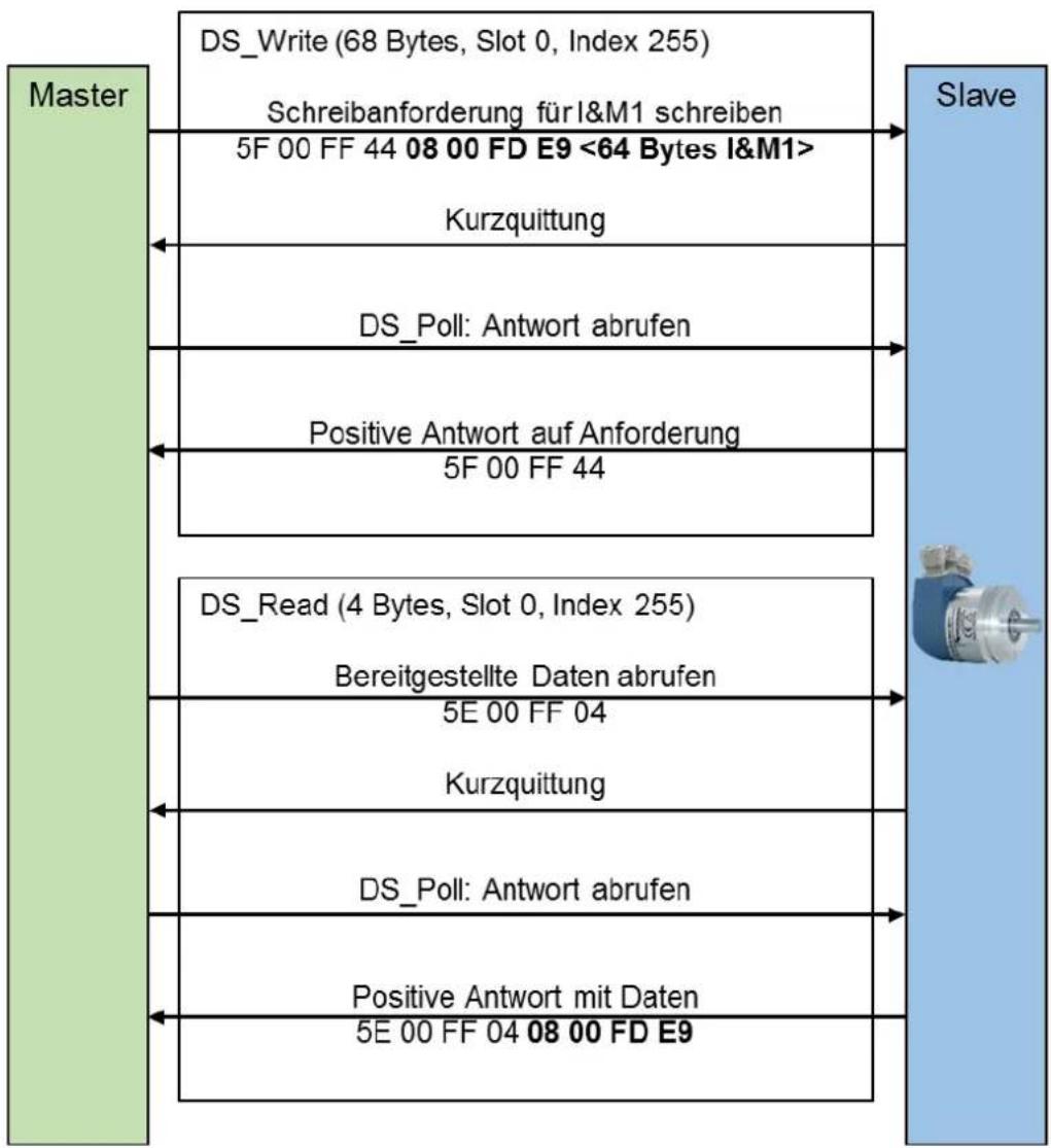
Figure 7.8: Writing - I&M1 data
The example in the Figure 7.9 shows the error handling. Error messages are issued in the event that an attempt is made to access a non-existent I&M data block, or an attempt is made to write to I&M0.
The highlighted printed octets are the user data of the DS_WRITE service.

flowchart
graph LR
    A["Master"] --> B["DS_Write (68 Bytes, Slot 0, Index 255)"]
    B --> C["Schreibanforderung für I&M0 schreiben"]
    C --> D["5F 00 FF 44 08 00 FD E8 <64 Bytes I&M0>"]
    D --> E["Kurzquittung"]
    E --> F["Slave"]
    F --> G["DS_Poll: Antwort abrufen"]
    G --> H["Negative Antwort auf Anforderung"]
    H --> I["BF 80 B6 00"]
Figure 7.9: Error handling
The error messages listed in Table 7.22 are possible.
| error code | significance |
| 80 B8 00 | Error message from DS_Write when trying to write to I&M0 or the data length of the write request is unequal 68. |
| 80 B6 00 | Error message from DS_Write if "extended FN" is not equal to 8. |
| 80 B5 00 | Error message from DS_Read, if no request was previously written with DS_Write. |
| 80 B0 00 | Error message from DS_Write when trying to access invalid slot-index-IM_Index combinations. |
Table 7.22: Error messages
7.13 Slave cross traffic - DxB
Slave cross-traffic is an extension of cyclic data exchange. It is used to send the process data of a DP slave directly to one or more other DP slaves. DP-V2 slaves can be parameterized as publishers or as subscribers. Publishers publish their input data and subscribers subscribe to the data of one or more publishers. The configuration of a DP slave as a publisher is trivial. In the configuration tool the DP slave is defined as Publisher, this causes the DP master to set Octet 7 Bit 7 (Publisher_Enable) in the parameterization telegram.
During data exchange, the DP slave responds with a broadcast receiver address which can be received by any subscriber. Each subscriber contains its own table that defines which publishers should be subscribed to. How this table is configured and how the subscriber's data is processed is not covered in this manual.

- As sensors, WDGA encoders only support the Publisher function.
- Only relevant for class 4 encoders
7.14 Isochronous mode - IsoM
The isochronous mode is an operating mode in which the DP master specifies the time at which the input data is to be collected and the output data is to be output to the DP slaves. This ensures that despite sequential communication of the DP master with the individual DP slaves, all process data were valid (input data) or will be valid (output data) at a certain time.
The time Ti determines the age of the input data. This must not be longer than the DP cycle time. However, it must be greater than the minimum required data acquisition time of the slowest DP slave in the network.
The time T0 determines the time offset of the output value. This must also not be longer than the DP cycle time. It must be greater than the time required for data exchange with all DP slaves. This depends on the number of DP slaves to be addressed and the configuration of the bus transmission.
The configuration of these times is performed by the configuration tool of the controller and is based on the information in the GSD files of the individual DP slaves.

- Only relevant for class 4 encoders
To synchronize the DP slaves to a common clock, the DP master sends a clock beat telegram at the beginning of each DP cycle. The DP slaves monitor the clock beat telegram and adjust their internal clocks accordingly, so that all data acquisition and data output are exactly within one microsecond of each other.

Since the cyclically running control program usually requires more time than a DP cycle, it may be necessary to run through several DP cycles per master cycle (see Figure 7.11). It must be assumed that the controller will not send any valid data in the subsequent DP cycles. The DP slaves must therefore determine which DP cycle coincides with the start of a DP master cycle. For this purpose, the DP master sends a "master sign of life" as part of the output data, which is increased by one by the control program with each pass. As soon as a DP slave detects that the "master sign of life" has been incremented, it also increases its "slave sign of life". Since the "slave sign of life" is also part of the cyclic data exchange, the control program can determine when the entire system is synchronized with the DP master cycle. This enables mutual monitoring of the DP master and DP slave applications and measures can be taken in the event that the real-time requirements of the overall system are no longer met.

flowchart
graph LR
    A["PA"] --> B["Master"]
    B --> C["PE"]
    C --> D["E"]
    D --> E["Zyklischer Programmablauf"]
    E --> F["A"]
    F --> G["PA"]
    G --> H["PE"]
    H --> I["Time axis"]
    I --> J["DP-Zyklus"]
    J --> K["Time axis"]
    K --> L["DP-Zyklus"]
    L --> M["Time axis"]
    M --> N["Time axis"]
Figure 7.11: DP master and DP cycle
7.15 Application profiles
For a failure-free system between the automation solution and the bus participants, the basic functions and services must match. The prerequisites for this are the same terminology and data formats for communication, device functions and industry solutions. This standardization takes place via the "application profiles". A distinction is made between device profiles, industry profiles and integration profiles.
The application profiles used by Wachendorff are listed in Table 7.26
| General application profile | profile content | device class | PNO-No.: |
| Identification & Maintenance (I&M)V1.2 (Oct., 2009) | Specifies the concept for storing device-specific data of the PROFIBUS device. Enables uniform access of the operator to all device-specific data | class3 + 4 | 3.502 |
| Special application profile | profile content | device class | PNO-No.: |
| Encoder profiles 1.1(May, 1997) | Coupling of encoders with ST and MT resolution; based on DP-V0 functions | class1 + 2 | 3.062 |
| Encoder profiles 4.1(Dec., 2008) | Coupling of encoders with ST and MT resolution; Based on DP-V1/V2 functions | class3 + 4 | 3.162 |
| PROFIdrive 4.1(May, 2006) | Device behavior and data access method for variable speed electronic drives on PROFIBUS | class3 + 4 | 3.172 |
Table 7.23: Application profiles
The application profile "I&M" is contained in a class 3 or 4 encoder. This makes it possible to read out the profiles used, the encoder type, the manufacturer, the serial number, etc.
7.15.1 Encoder profiles
Encoder profile 4.1 is the device profile for rotary encoders. Encoder Profile 4.1 implements class 3 and 4.
The standard profile for drive technology with PROFIBUS and PROFINET is PROFIdrive (only for: DP-V1/V2, see Figure 7.12). This allows a simple coupling of drives and controls independent of the manufacturer.
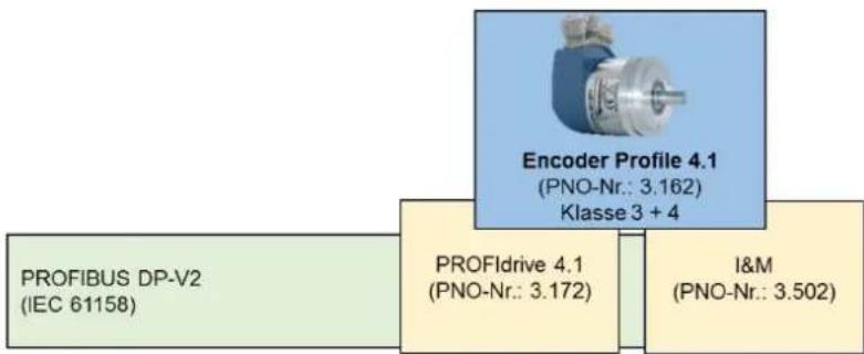
Depending on the power level (see section 7.5.1), different functions and additional extensions are available. Table 7.24 shows the different services depending on the power level (DP-V0, DP-V1 and DP-V2) and the device classes of the encoder.
| power level | rotary encoder Class 3 | rotary encoder Class 4 |
| DP-V0 | ||
| cyclic data exchange | P | P |
| parameterisation | P | P |
| configuration | P | P |
| diagnosis | P | P |
| DP-V1 | ||
| acyclic data exchange | P | P |
| I&M | P | P |
| acyclic parameter access | P | P |
| DP-V2 | ||
| Data Exchange Broadcast (DxB) | O | P |
| Isochronous Mode (IsoM) | O | P |
| time synchronization | O | O |
| redundancy | O | O |
Table 7.24: Power level and class division
 | An encoder is divided into four classes.The WDGA encoders contain mandatory Class 4 functionalities. |
7.15.2 PROFIdrive
PROFIdrive is an application-oriented standard profile for drive technology and is standardized in IEC 61800-7 for PROFIBUS and PROFINET. The standardization enables the drive user to communicate between different drive components independent of the manufacturer.
The PROFIdrive architecture describes the communication-independent functions in the basic, parameter and application model. If PROFIdrive is mapped to PROFIBUS-DP, the PROFIdrive communication model (see Figure 7.13) is transferred to the PROFIBUS-DP communication model (see Figure 7.14).

flowchart
graph TD
    A["P-Device (Drive Unit)"] -->|DO IO Data (Drive to Drive)| B["Controller (e.g. PLC)"]
    B -->|Parameter-Access| A
    A -->|Parameter-Access| C["Supervisor (e.g. PC for Start up Maintenance and Unagonist)"]
    style A fill:#f9f,stroke:#333
    style B fill:#ccf,stroke:#333
    style C fill:#cfc,stroke:#333
    subgraph Clock cycle synchronous communication
        D["Clock cycle synchronous communication"]
        E["DO IO Data"]
    end
    subgraph DO IO Data
        F["DO IO Data"]
        G["DO IO Data"]
        H["DO IO Data"]
    end
    subgraph Parameter-Access
        I["Parameter-Access"]
        J["Parameter-Access"]
        K["Parameter-Access"]
    end
    D -->|Acyclic communication| A
    E -->|Acyclic communication| B
    F -->|Acyclic communication| C
    G -->|Acyclic communication| D
    H -->|Acyclic communication| E
    I -->|Cyclic communication| F
    J -->|Cyclic communication| G
    K -->|Cyclic communication| H
Figure 7.13: Communication model - PROFIdrive

flowchart
graph TD
    A["DPM1 (Controller)"] -->|MS1| B["Clock cycle synchronous communication"]
    A -->|MS0| C["DxB"]
    B --> D["DP-Slave (P-Device)"]
    C --> D
    D --> E["Acyclic communication"]
    D --> F["Cyclic communication"]
    G["DPM2 (Supervisor)"] --> H["MS2"]
    H --> I["Green arrow"]
    I --> J["Red arrow"]
    J --> K["Green arrow"]
    K --> L["Green arrow"]
    L --> M["Green arrow"]
    M --> N["Green arrow"]
    N --> O["Green arrow"]
    O --> P["Green arrow"]
    P --> Q["Green arrow"]
    Q --> R["Green arrow"]
    R --> S["Green arrow"]
    S --> T["Green arrow"]
    T --> U["Green arrow"]
Figure 7.14: Communication Model - Illustration on PROFIBUS-DP
The PROFIBUS standard profile specifies, for example, that the standard telegram 81 - 98 (PNU922) is reserved for the encoder profiles. In addition, the structure of the status and control words is defined therein. Device manufacturer-specific telegrams are reserved under the standard telegram number 100 - 60000.

- Details on PROFIdrive can be found in the PROFIdrive profile.
7.16 Debug control word
As a special feature of the WDGA encoders, there is an additional manufacturer-specific telegram for both encoder profiles, which contains a debug control and status word (see Table 7.25 and Table 7.26).
| 15 | 14 | 13 | 12 | 11 | 10 | 9 | 8 | 7 | 6 | 5 | 4 | 3 | 2 | 1 | 0 |
| 0 | 0 | 0 | 0 | 0 | 0 | 0 | 0 | 0 | 0 | 0 | 0 | 0 | 0 | Enable slave address | test error |
Table 7.25: Debug_STW
| 15 | 14 | 13 | 12 | 11 | 10 | 9 | 8 | 7 | 6 | 5 | 4 | 3 | 2 | 1 | 0 |
| 0 | 0 | 0 | 0 | 0 | 0 | 0 | 0 | 0 | 0 | 0 | 0 | 0 | 0 | Slave address fixed | test error active |
Table 7.26: Debug_ZSW
The "test error" is useful when testing the error handling of a control program. With a rotary encoder it is not possible to provoke an error without further ado. Test error" simulates an error in which bit 0 of "Debug_STW" is set (see Table 7.25). Bit 0 of "Debug_ZSW" indicates whether the "test error" is currently active (see Table 7.26).

- It should be noted that the diagnostic interrupt triggered by this must be acknowledged at class 4, even if the test error has been reset to inactive.
When setting the DP slave address on the software side, it is possible to block the future change of the DP slave address via a configuration tool. A manufacturer-specific solution is required to remove this lock. Since there are no physical switches on the encoder that can be reached during operation, the lock can only be released via the debug control word (see Table 7.25). If the "Slave address is fixed", this can be recognized by bit 1 of "Debug_ZSW". To release the lock "Slave address fixed", bit 1 - "Enable slave address" - of "Debug_STW" must be set until bit 1 of "Debug_ZSW" is reset.
8 FAQ
8.1 Project planning
- How is the resolution of the encoder set?
Class 4:
The resolution is set via the parameterization (see section 5.3.3).
- How is the encoder preset set and saved?
Class 4:
see section 5.6
- How is the position of the encoder read out?
Class 4:
see section 5.5
- How can the direction of rotation of the encoder be changed?
Class 4:
The direction of rotation is set via the parameterization.
(see section 5.3.3).
The class 4 function must be active.
- How can diagnostic messages from the encoder be read?
Class 4:
see section 5.8
8.2 LED signalling - Rotary encoder
The BUS LED lights red and the DEV LED lights green?
This is due to the installation:
- Are all PROFIBUS cables correctly connected in the network?
Check your system planning with regard to PROFIBUS cabling.
• PROFIBUS cable is connected, but has no connection:
Is there a wire break?
Exclude loose contacts etc.
(Note also: self-assembled plugs)
Are A and B switched in the bus cover?
- Is the PROFIBUS address of the rotary coding switches consistent with the parameterization of the PROFIBUS system?
Check the setting of the rotary coding switches or the assignment of the PROFIBUS address in the "HW konfig".
• Is the PROFIBUS address unique?
See also 4.4.2 and 4.5.1
- Was the scheduling carried out correctly?
Termination at the last participant of the segment (see also 7.3.3)
The cause lies in the project engineering:
- Has the encoder been correctly integrated into the control system?
Check your hardware configuration and S7 programming
- The encoder was correctly integrated into the control system:
Has the project been translated and transferred to the target system?
The BUS LED flashes red and the DEV LED flashes green?
- Have you set the parameters correctly?
Are the values for "Measuring units per revolution" and "Total measuring range in measuring units" within the permissible value range?
Were both values for "Measuring units per revolution" and "Total measuring range in measuring units" adjusted accordingly (see example under Fehler! Verweisquelle konnte nicht gefunden werden.)?
• Further information can be found in section 3.4

- For more information, see the Table 3.1
9 Technical support
Technical application advisor
Do you have any questions about this product?
Our technical application advisor will be pleased to help you.
Tel.: +49 (0) 67 22 / 99 65 414
E-Mail: support-wa@wachendorff.de
Notes:



- Technical Manual
- Absolute Encoders WDGA
- with PROFIBUS interface
- Impressum
- Guarantee waiver, right of amendment, copyright protection:
- Introduction .... 1
- Safety information....5
- Device description....7
- Installation....18
- Project planning 32
- Encoders - Class 4 ....48
- PROFIBUS....83
- Index of figures
- Index of tables
- Introduction
- About this manual
- Symbols
- You will not find the following in this manual:
- Product assignment
- Solid shaft absolute encoders:
- End hollow shaft absolute encoders:
- Specifications
- Scope of delivery
- Safety information
- General safety information
- Intended use
- Safe working
- Disposal
- Device description
- General information
- WDGA - Basics
- Singleturn - ST
- Multiturn - MT (EnDra®)
- Direction of rotation
- Preset
- Scaling
- Default settings
- General information
- Rotary encoder - with bus cover
- Rotary encoder - without bus cover
- LED signalling
- BP1 - Bus cover with 3x PG screw connection
- BP2 - Bus cover with 3x M12
- DB4 - without bus cover 2x M12, 1x M8
- SD9/SE9 - without bus cover, D-Sub
- Rotary encoder and bus cover label
- GSD file
- Installation
- General information
- Mechanical connection
- Shaft encoder
- Hollow shaft encoders
- Shielding
- Connecting the encoder - with bus cover
- General information
- Setting the slave address
- Termination
- Connecting the signal and supply lines
- An installation example is shown below:
- Connecting the encoder - without bus cover
- Setting the slave address
- Termination
- Connecting the signal and supply lines
- SD9/SE9 - D-Sub
- Project planning
- General information
- Installing the GSD file
- Integration of the WDGA
- Communicating the slave address
- Setting I/O addresses
- Parameterization - Class 4
- Set diagnostic address
- Creating the Symbol Table
- Observe position and speed:
- Load position and velocity into a control program:
- Set preset value - Class 4
- Step one:
- Step two:
- Step three:
- Step four:
- Step five:
- Error management
- Reading the diagnosis
- S7 sample program
- Encoders - Class 4
- General information
- Configuration
- Telegram structures
- Signal list
- Parameterisation
- Code sequence
- Class 4 functionality
- G1\_XIST1 preset control
- Scaling function control
- Alarm channel control
- Compatibility mode
- Measuring units per revolution
- Total measuring range
- Speed measuring unit
- Exchange of data
- Telegram structure
- G1\_STW
- "Activate parking" - Park sensor
- "Relative preset mode" - Preset absolute/relative
- G1\_ZSW
- Bit "Sensor error":
- G1\_XIST1
- G1\_XIST2
- G1\_XIST2 - Error management
- G1\_XIST3
- NIST\_A & NIST\_B
- Debug\_STW & Debug\_ZSW
- STW2\_ENC & ZSW2\_ENC
- Control by PLC/request - Control priority
- Diagnosis
- I&M functions
- I&M0
- I&M1
- I&M2
- I&M3
- I&M4
- Acyclic parameter access
- Basics
- Read parameters
- Write parameters
- Error handling
- PROFIdrive parameters
- Manufacturer specific parameters
- Encoder-specific parameters
- Slave cross traffic - DxB
- Isochronous mode - IsoM
- State machine
- Offline
- Preparation Phase 1
- Preparation Phase 2
- Synchronisation
- Surgery
- PROFIBUS
- General information
- Attendee
- Physical Layer - Layer 1
- Bus line
- Transmission speed
- Termination
- Data Link Layer - Layer 2
- General information
- Bus access method
- Application Layer - Layer 7
- Communication protocol - DP-V0, DP-V1, DP-V2
- Communication relationships
- MS0 communication relationship
- MS1 communication relationship
- MS2 communication relationship
- DP slave state machine
- Parameterisation
- General information
- Telegram structure - Standard parameterization
- Telegram structure - DP-V1 parameter
- Parameter block for isochronous parameters
- Configuration
- Diagnosis
- Extended Diagnosis
- Identifier related diagnosis
- Channel related diagnosis
- Device related diagnosis
- Modules status
- Diagnosis alarm
- Exchange of data
- I&M functions
- Slave cross traffic - DxB
- Isochronous mode - IsoM
- Application profiles
- Encoder profiles
- PROFIdrive
- Debug control word
- FAQ
- Project planning
- Class 4:
- LED signalling - Rotary encoder
- Technical support
- Technical application advisor
Brand : Wachendorff
Model : WDGA 58E
Category : Industrial sensor