
WDGA 58S - Unknown Wachendorff - Free user manual and instructions
Find the device manual for free WDGA 58S Wachendorff in PDF.

| Product Type | Absolute Rotary Encoder with IO-Link |
| Model | WDGA 58S |
| Brand | Wachendorff |
| Series | WDGA |
| Flange Diameter | 58 mm |
| Shaft Type | Solid or hollow shaft (depends on variant) |
| Interface | IO-Link (IEC 61131-9) |
| Baud Rate | COM3 (230.4 kBit/s) |
| Supported Profiles | SSP 4.2.1, SSP 4.2.2, 64-Bit |
| Singleturn Technology | QuattroMag® magnetic |
| Multiturn Technology | EnDra® (wireless, no battery) |
| Singleturn Resolution | Up to 16 bits (per revolution) |
| Multiturn Resolution | Up to 12 bits (4096 revolutions) |
| Total Resolution | Up to 28 bits (combined) |
| Connector Type | M12x1 (5-pin, axial or radial) |
| Supply Voltage | 10...30 V DC (typical) |
| Operating Temperature | -40°C to +85°C (estimated from typical industrial range) |
| Protection Class | IP67 (typical for WDGA series) |
| LED Indication | Status LED (multicolor) for device status, events, ping |
| Preset Function | One-button teach at reference position |
| Scaling | Programmable MUPR and TMR (gear ratio available) |
| Switching Signal Channel (SSC) | Up to 2 channels position, up to 2 velocity (SSP4.2.2) |
| Diagnostics | Temperature, signal quality, event logging, overspeed |
| Maintenance | Maintenance-free due to EnDra and QuattroMag |
| Safety | Not for safety-critical applications; component for industrial machines |
Frequently Asked Questions - WDGA 58S Wachendorff
User questions about WDGA 58S Wachendorff
0 question about this device. Answer the ones you know or ask your own.
Ask a new question about this device
Download the instructions for your Unknown in PDF format for free! Find your manual WDGA 58S - Wachendorff and take your electronic device back in hand. On this page are published all the documents necessary for the use of your device. WDGA 58S by Wachendorff.
USER MANUAL WDGA 58S Wachendorff
natural_image
Infographic with eight hexagonal icons representing industrial and renewable energy sectors (no text or symbols)Technical Manual
Absolute Encoders WDGA
with IO-Link interface

wachendorff-automation.com

IO-Link
EnDra®
Technologie

Legal information


Managing Director: Robert Wachendorff
Warranty waiver, right of amendment, copyright:
Wachendorff Automation accepts no liability or warranty for the correctness of this manual, or for any direct or indirect damage that may arise from it. In the pursuit of constant innovation and cooperation with customers, we reserve the right to amend technical data or content at any time.
Wachendorff Automation asserts copyright over this manual. It may not be modified, added to, reproduced or shared with third parties without prior written consent.
Comments:
Should you have any corrections, notes or requests for changes, please send them to us. Send your comments to: wdg@wachendorff.de
1 Introduction .... 1
1.1 About this manual.... 1
1.1.1 Explanation of symbols 2
1.1.2 What you won't find in the manual.... 2
1.2 Product allocation.... 3
1.3 Service description.... 3
1.4 Scope of delivery.... 4
2 Safety instructions ....5
2.1 General information....5
2.2 Intended use....5
2.3 Safe working....6
2.4 Waste disposal 6
3 Device description....7
3.1 General 7
3.2 IO-Link 8
3.3 WDGA - Basics 8
3.3.1 Singleturn - ST (QuattroMag®) 8
3.3.2 Multiturn - MT (EnDra®) 9
3.3.3 Direction of rotation....9
3.3.4 Preset....9
3.3.5 Scaling 9
3.4 IO-Link encoder connection assignments 11
3.4.1 IB5 / IC5 - M12x1 connection.... 11
3.5 LEDs and signaling 12
4 IO-Link....13
4.1 Overview of functions.... 13
4.2 IO Device Description.... 13
4.3 Standard parameters.... 13
4.3.1 Standard parameter identification 13
4.3.2 Standard parameter system commands 14
4.3.3 Standard parameter events.... 16
4.4 Process data 18
4.4.1 Smart Sensor Profile 4.2.1 18
4.4.2 Smart Sensor Profile 4.2.2 18
4.4.3 64-Bit Profil....19
4.5 Configuration and diagnostic parameters.... 20
4.6 Switching Signal Channel (CAM) 26
4.6.1 Single Point 26
4.6.2 Window mode 27
4.6.3 Two point mode.... 27
5 Technical advice....28
Index of figures
Figure 3.1: WDGA with IO-Link 7
Figure 4.1: Single Point mode 1 26
Figure 3.1: Single Point mode 2 26
Figure 3.1: Window mode....27
Figure 3.1: Two point mode increasing....27
Figure 3.1: Two point mode decreasing....27
Index of tables
Table 3.1: Pin-assignment.... 11
Table 3.2: LED signaling....12
Table 4.1: Functions 13
Table 4.2: IODDs....13
Table 4.3: Identification parameters 13
Table 4.4: System commands .... 15
Table 4.5: Standard parameter events ...... 17
Table 4.6: Process data SSP 4.2.1....18
Table 4.7: Process data SSP 4.2.2....18
Table 4.8: Process data 64-Bit 19
Table 4.9: Configuration and diagnostic parameters 25
1 Introduction
1.1 About this manual
This technical manual describes the configuration and installation options for Wachendorff Automation absolute rotary encoders with an
IO-Link interface. It is a supplement to the other public Wachendorff Automation documents, such as the data sheets, installation instructions, supplementary sheets, catalogues and flyers.
Read the manual before commissioning. First check that you have the latest version of the manual.
When reading, pay particular attention to the information, important notes and warnings marked with the corresponding symbols (see 1.1.1)
This manual is intended for people with technical knowledge of sensors, IO-Link interfaces and automation elements. If you have no experience with this topic, first seek the help of experienced persons.
Please keep the information supplied with our product in a safe place so that you can obtain further information if necessary or at a later date.

- The contents of this manual are arranged in a practice-oriented manner.
- All the information in the following chapters is required for optimum use of the device and should be read carefully.
1.1.1 Explanation of symbols
 | The INFO symbol is next to a section that is particularly informative or important for the further procedure with the device. |
 | The IMPORTANT symbol is placed next to a text passage in which a procedure for solving a specific problem is described. |
 | The WARN symbol is located next to a text passage that must be observed in particular to ensure proper use and to protect against hazards. |
1.1.2 What you won't find in the manual
- Basics of automation technology
- System planning
- Risk (availability, security)
- Shielding concepts
- Reflections
- Repeater
- Network design
- Bus cycle time
- FMA - Management services
- Transmission services
- Telegram types
1.2 Product allocation
This manual is to be assigned to the following encoder types from Wachendorff Automation with the corresponding article identification:
Full shaft encoder and final hollow shaft encoder absolute:
• WDGA 36 IO-Link
• WDGA 58 IO-Link

- You can find the Wachendorff IO-Link product range on our website: https://www.wachendorff-automation.com
1.3 Service description
A rotary encoder is a sensor for detecting angular positions (single turn) and rotations (multiturn). The measurement data and the variables derived from it are processed by the encoder and provided as electrical output signals for the downstream peripherals.
The WDGA series uses the patented QuattroMag® technology for single turn and EnDra® for multiturn. This makes the WDGA series from Wachendorff particularly maintenance-free and environmentally friendly.
The rotary encoders with the article identifiers as described in section 1.2 communicate via the IO-Link interface.
1.4 Scope of delivery
The scope of delivery depends on the type of model and your order. Before commissioning, you should check that the scope of delivery is complete.
As a rule, the WDGA product range with an IO-Link interface includes the following scope of delivery:
- WDGA with IO-Link
- Assembly instructions

- The corresponding IODD file and the corresponding data sheet are available for download on the Internet: www.wachendorff-automation.com
2 Safety instructions
2.1 General information

- The installation instructions, manual and data sheet must be observed when commissioning the encoder.
- Failure to observe the safety instructions can lead to malfunctions, property damage and personal injury!
- The machine manufacturer's operating instructions must be observed.
2.2 Intended use
Rotary encoders are components for installation in machines. Before commissioning (operation as intended), it must be established that the machine as a whole complies with the EMC and Machinery Directives.
The rotary encoder is a sensor for detecting angular positions and rotations and is only to be used for this purpose! Wachendorff Automation rotary encoders are manufactured and sold for industrial use in non-safety-relevant areas.

- The rotary encoder must not be operated outside the specified limit parameters (see associated data sheet).
2.3 Safe working
The encoder may only be installed and fitted by a qualified electrician.
National and international regulations must be observed when installing electrical systems.
If the encoder is not commissioned correctly, it may malfunction or fail.

- All electrical connections must be checked before commissioning.
- Suitable safety measures must be taken to ensure that no persons are injured in the event of failure or malfunction and that no damage is caused to the system or operating equipment.
2.4 Waste disposal
Devices that are no longer required or are defective must be disposed of properly by the user in accordance with the country-specific laws. It should be noted that this is special electronic waste and disposal with normal household waste is not permitted.
The manufacturer is not obliged to take back the product. If you have any questions about proper disposal, please contact a specialist disposal company in your area.
3 Device description
3.1 General
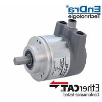
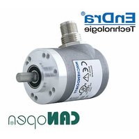
There are different mechanical variants for the WDGA series with IO-Link. The decisive factor here is the type of flange shape and the type of shaft (solid or hollow shaft). The size is determined by the diameter of the flange, e.g. 36 mm. The following illustration shows examples of the WDGA series with IO-Link.

natural_image
Two metallic industrial sensors with attached connectors and mounting brackets, labeled 'IO-Link' below (no visible text on main body)Figure 3.1: WDGA with IO-Link
The solid or hollow end shaft is connected to the rotating part whose angular position or speed is to be measured. Connector outlets form the interface for connection to the IO-Link network. The status LEDs in the cover signal various states of the encoder during use. They support the configuration of the encoder or troubleshooting in the field. The flange holes or the supplied spring plates are used for mounting on the machine or in the application.
3.2 IO-Link
IO-Link is an industrial communication protocol for connecting sensors and actuators with automation systems. It was developed by the IO-Link community and is managed as an international standard (IEC 61131-9). IO-Link enables bidirectional communication and transmits both process data and device parameters.
IO-Link uses a point-to-point connection and can be integrated into various network topologies. It supports simple cabling via standard industrial cables and offers diagnostic functions as well as the option of automatic device parameterization.
3.3 WDGA - Basics
The following sections describe the basic functions of an absolute rotary encoder.
In contrast to incremental encoders, absolute encoders output their position value as a digital number via a fieldbus, for example. A distinction is made between single turn and multiturn encoders.
In addition to the simple output of the position value, most rotary encoders allow a certain degree of parameterization, such as selecting the positive direction of rotation, setting the position value to a reference value at a defined physical position and scaling the position value to any resolution and a limited measuring range. In this way, the development effort in the control program is reduced and the computing capacity of the controller is relieved.
3.3.1 Single turn - ST (QuattroMag®)
Measuring the angle from 0^ to 360^ using a shaft is the minimum function of a rotary encoder. The sensor technology is based on the optical or magnetic scanning of a measuring scale on the encoder shaft
The WDGA encoders from Wachendorff work with the new magnetic QuattroMag® technology, which guarantees the highest possible accuracy and resolution of the single turn.
3.3.2 Multiturn - MT (EnDra®)
A multiturn encoder enables the number of revolutions to be recorded. This is realized via a revolution counter. EnDra® technology is used in the WDGA encoders to ensure that the relevant information is retained even in a de-energized state. Buffer batteries and gearboxes, which require a comparatively large installation space and corresponding maintenance effort, can therefore be replaced.
3.3.3 Direction of rotation
The positive direction of rotation can be reversed by a simple two's complement (invert each bit and add "1") of the position value.
3.3.4 Preset
A desired position value can be assigned to the rotary encoder for a specific physical position. This must be within the measuring range so that the position value is correlated with a physical reference position. To do this, the difference between the current position value and the desired value is calculated. This is saved in a non-volatile memory and added to the position value as an offset.
3.3.5 Scaling
The scaling parameters can be used to adjust the position value to exactly match the physical quantity to be measured. The scalable parameters are "Measuring units per revolution (MUPR)" and "Total measuring range in measuring units (TMR)".
The scaling parameter "Measuring units per revolution (MUPR)" - increments per revolution - specifies the resolution of the position value per revolution (also: ST resolution). The value corresponds to 360°. This means that if a value of 3600 Cts is parameterized, the rotary encoder outputs the position in 0.1° increments (see equation (2)).
$$ M U P R = S T = 3 6 0 0 C t s \tag {1} $$
$$ W i n k e l s c h r i t t e = \frac {W i n k e l e i n e r U m d r e h u n g}{M U P R} = \frac {3 6 0 ^ {\circ}}{3 6 0 0 C t s} = 0, 1 ^ {\circ} / C t s \tag {2} $$
The scaling parameter "Total measuring range in measuring units (TMR)" - maximum total measuring range of the position value (singleturn and multiturn multiplied) - specifies the total resolution of the rotary encoder. If the position value reaches TMR - 1, it jumps back to 0 and vice versa.
As a rule, the TMR parameter is selected so that it is an integer multiple of the "Measuring units per revolution (MUPR)" (see equation (4)), so that the zero point is always at the same position on the encoder shaft.
$$ T M R = 3 6 0 0 0 C t s \tag {3} $$
$$ M T = \frac {T M R}{M U P R} = \frac {3 6 0 0 0 C t s}{3 6 0 0 C t s} = 1 0 \tag {4} $$
In exceptional cases, it is adequate that TMR is not an integer multiple of MUPR. For example, if a transmission ratio in a system ensures that the desired measured variable moves 10% faster than the encoder shaft in relation to the encoder shaft.
Then a setting of MUPR = 3960 Cts and TMR = 36000 Cts would ensure that the faster but not directly measurable shaft can be measured with a resolution of 0.1^ and over a range of 10 revolutions. Normally, the number of revolutions would be calculated by dividing the position value by MUPR. In this case, however, it must be divided by 3600 Cts, as the result would otherwise be the number of revolutions of the encoder shaft and not that of the faster shaft of the system.

- Please note that measurement errors occur if the result of this formula is a decimal number.
3.4 IO-Link encoder connection assignments
3.4.1 IB5 / IC5 - M12x1 connection
The character sequence IB5(axial) / IC5(radial) in the order code indicates a rotary encoder with M12 connector. The pin assignment of the connector can be found in Table 3.1.
| Pin-assignment | |
| IB5 / IC5 | |
| Plug (Ref.) | M12x1 |
| L+ | 1 |
| L - | 3 |
| C/Q | 4 |
| I | 2 |
| n. c. | 5 |
Table 3.1: Pin-assignment
3.5 LEDs and signalling
A status LED in the housing indicates various statuses of the rotary encoder and supports diagnostics and troubleshooting in the field (see Table 3.2)
| Status LED | Meaning | Cause |
| [WZSA] | No voltage | |
 | Ready for operation | The appliance has been fully commissioned. |
| [2T46] | Pre-/Operational | The device has been fully commissioned and is in preoperational or operational mode. |
| [6ADS] | Event (Level: Warning) | The device has been fully commissioned, and an event has been triggered (e.g. Operating Temperature Upper Threshold Exceeded) |
| [YH04] | Ping | The device has been fully commissioned, and the device discovery function has been activated. See4.3.2 in 0xAF |
| [XOZY] | Event (Level: Error) | The device has detected a serious error. (Please contact support) |
Table 3.2: LED signalling
Explanation of the symbols and asterisks:

LED off /● LED on //★ ★ ★ ★ /LED flashes
4 IO-Link
4.1 Overview of functions
Our IO-Link encoders support the functions shown in Table 4.1 :
| Functions | Meaning |
| Specification | V1.1.4 |
| Baudrate | COM3 (230,4kBit/s) |
| Profile | SSP 4.2.1: Measuring and Switching Sensor, high resolution, 1 channelSSP 4.2.2: Measuring and Switching Sensor, high resolution, 2 channel64-Bit Profil |
Table 4.1: Functions
4.2 IO Device Description
The available IODDs for the corresponding profiles are listed in Table 4.2:
| Functions | Meaning |
| Wachendorff-Encoder-SSP421-xxx.xml | If profile 4.2.1 is set in the device, this IODD must be used |
| Wachendorff-Encoder-SSP422-xxx.xml | If profile 4.2.2 is set in the device, this IODD must be used |
| Wachendorff-Encoder-64Bit-xxx.xml | If the 64-bit profile is set in the device, this IODD must be used |
Table 4.2: IODDs
4.3 Standard parameters
4.3.1 Standard parameter identification
| Parameter | Index | Subindex |
| Vendor Name | 0x10 | 0 |
| Vendor Text | 0x11 | 0 |
| Product Name | 0x12 | 0 |
| Product ID | 0x13 | 0 |
| Product Text | 0x14 | 0 |
| Serial Number | 0x15 | 0 |
| HW Revision | 0x16 | 0 |
| FW Revision | 0x17 | 0 |
| Application specific tag | 0x18 | 0 |
| Function Tag | 0x19 | 0 |
| Location Tag | 0x20 | 0 |
Table 4.3: Identification parameters
4.3.2 Standard parameter system commands
| System commands | Name | Definition |
| 0x01 | ParamUploadStart | Start parameter upload |
| 0x02 | ParamUploadStop | Stop parameter upload |
| 0x03 | ParamDownloadStart | Start parameter download |
| 0x04 | ParamDownloadStop | Stop parameter download |
| 0x05 | ParamDownloadStore | Finalize parameterization and start Data Storage |
| 0x06 | ParamBreak | Cancel all Param commands |
| 0x40 | Teach Apply | Verifies the Teach points and applies them to the configuration |
| 0x41 | SP1 Single Value Teach | Saves the currently measured position as Setpoint 1 |
| 0x42 | SP2 Single Value Teach | Saves the currently measured position as Setpoint 2 |
| 0x43 | SP1 Two Value Teach TP1 | Saves the currently measured position as Teachpoint 1 for Setpoint 1 |
| 0x44 | SP1 Two Value Teach TP2 | Saves the currently measured position as Teachpoint 2 for Setpoint 1 |
| 0x45 | SP2 Two Value Teach TP1 | Saves the currently measured position as Teachpoint 1 for Setpoint 2 |
| 0x46 | SP2 Two Value Teach TP2 | Saves the currently measured position as Teachpoint 2 for Setpoint 2 |
| 0x4E | Teach Reset | Deletes settings, SP1 and SP2 value of the currently selected SSC |
| 0x4F | Teach Cancel | Cancels the current Teach procedure |
| 0x80 | Device reset | A warm start is performed and the device is set to initial mode.Communication is interrupted by the device and restored by the master. |
| 0x81 | Application reset | The device parameters are set to the default values. Identification parameters remain unaffected. An upload to the master's data storage is carried out if this is activated. |
| 0x82 | Restore factory settings | All device parameters are reset to the default settings.The values stored in the data storage can be downloaded after the power reset. |
| 0x83 | Back-to-box | All device parameters are reset to the default settings and communication is suspended until the next power reset.Note: If you carry out this reset, the device should be disconnected from the master after it has been carried out. |
| 0xA0 | Reset Maintenance | Resets all maintenance parameters like remanent errors, min/max temperature since startup, ... |
| 0xAF | Ping | LED changes to Device Discovery Blink pattern. See 3.5 |
| 0xE0 | Teach In Zero Point | Updates position value to the value that is stored in index 0x00C2(Measurement Preset) |
Table 4.4: System commands
4.3.3 Standard parameter events
| Event Id | Event | Type | Description |
| 0x4000 | IOLD_EVENT_TEMP ERATURE_FAULT_OVERLOAD | Error | Actual operating temperature is above maximum value or below minimum value |
| 0x4210 | IOLD_EVENT_DEVICE_TEMPERATURE_OVERRUN | Warning | This warning is generated if the actual operating temperature is above the maximum operating temperature specification decremented by 10°C. |
| 0x4220 | IOLD_EVENT_DEVICE_TEMPERATURE_UNDERRUN | Warning | This warning is generated if the actual operating temperature is below the minimum operating temperature specification incremented by 10°C. |
| 0x5000 | IOLD_EVENT_DEVICE_HARDWARE_FAULT | Error/Al arm, not recover able | Hardware error occurred, device must be exchanged |
| 0x6000 | IOLD_EVENT_DEVICE_SOFTWARE_FAULT | Error/Al arm, not recover able | Software error occurred, device must be exchanged |
| 0x8D18 | IOLD_EVENT_SIGNAL_COUNTER_MULTICHANNEL_REACH_LIMIT | Notification | One of the Switching counter channels reached its limit – check status |
| 0x8D19 | IOLD_EVENT_SIGNAL_COUNTER_MULTICHANNEL_OVERFLOW | Warning | One counter stopped because it overflowed the maximum value - check status of switching counters |
| 0x8CFF | IOLD_EVENT_LOW_SIGNAL_QUALITY | Error, recover able | Magnetic field is too weak or too strong, check environment |
| 0x8D10 | IOLD_EVENT_CUSTOMER_TEMPERATURE_MAX_TRESHOLD_OVERRUN | Warning | This warning is generated if the actual operating temperature is above the maximum operating temperature defined by the customer. |
| 0x8D20 | IOLD_EVENT_CUSTOMER_TEMPERATURE_MIN_TRESHOLD_UNDERRUN | Warning | This warning is generated if the actual operating temperature is below the minimum operating temperature defined by the customer. |
| 0x1848 | IOLD_EVENT_SINGLE_RETURN_MAGNETIC_FIELD_TOO_STRONG | Error | Magnetic field of sensor is too strong, maybe environmental magnetic field impacts the measurement |
| 0x1849 | IOLD_EVENT_SINGLE_RETURN_MAGNETIC_FIELD_TOO_WEAK | Error | Magnetic field of sensor is too weak, maybe magnet is broken |
| 0x184A | CALIBRATION_ERR OR | Error | Calibration of the device has failed. The device must be replaced. |
| 0x184B | ST_MT_SYNCRONIZATION_FAILED | Warning | ST/MT synchronization failed |
| 0x8D0A | IOLD_EVENT_SHORTCIRCUIT_PIN_4 | Error | ShortCircuit |
| 0x8D0B | IOLD_EVENT_SHORTCIRCUIT_PIN_2 | Error | ShortCircuit |
| 0x8D14 | IOLD_EVENT_OVERLOAD_PIN_4 | Warning | Overload |
| 0x8D15 | IOLD_EVENT_OVERLOAD_PIN_2 | Warning | Overload |
| 0x8D0C | IOLD_EVENT_WRO NG_LOAD_CABLE_BREACH_ANALOG_CURRENT_OUTPUT_PIN_4 | Warning | WireBreak |
| 0x8D0D | IOLD_EVENT_WRO NG_LOAD_CABLE_BREACH_ANALOG_CURRENT_OUTPUT_PIN_2 | Warning | WireBreak |
| 0x5110 | IOLD_EVENT_PRIMARY_SUPPLY_VOLTAGE_OVERRUN | Warning | Overvoltage |
Table 4.5: Standard parameter events
4.4 Process data
4.4.1 Smart Sensor Profile 4.2.1
| Description | Byte | 7(MSB) | 6 | 5 | 4 | 3 | 2 | 1 | 0(LSB) |
| Position value | 5 | max | |||||||
| Position value | 4 | ||||||||
| Position value | 3 | ||||||||
| Position value | 2 | 0 | |||||||
| Scale | 1 | ||||||||
| Device status | 0 | System error | res | res | Signal quality bad | res | Res | SSC1.2 State | SSC1.1 State |
Table 4.6: Process data SSP 4.2.1
4.4.2 Smart Sensor Profile 4.2.2
| Description | Byte | 7(MSB) | 6 | 5 | 4 | 3 | 2 | 1 | 0(LSB) |
| Position value | 11 | max | |||||||
| Position value | 10 | ||||||||
| Position value | 9 | ||||||||
| Position value | 8 | 0 | |||||||
| Position Scale | 7 | ||||||||
| Device status | 6 | System error | res | res | Signal quality bad | res | Res | SSC1.2 State | SSC1.1 State |
| Velocity value | 5 | max | |||||||
| Velocity value | 4 | ||||||||
| Velocity value | 3 | ||||||||
| Velocity value | 2 | 0 | |||||||
| Velocity Scale | 1 | ||||||||
| SSC Velocity state | 0 | res | res | res | res | res | Res | SSC2.2 State | SSC2.1 State |
Table 4.7: Process data SSP 4.2.2
4.4.3 64-Bit Profil
| Description | Byte | 7(MSB) | 6 | 5 | 4 | 3 | 2 | 1 | 0(LSB) |
| Position value | 12 | max | |||||||
| Position value | 11 | ||||||||
| Position value | 10 | ||||||||
| Position value | 9 | ||||||||
| Position value | 8 | ||||||||
| Position value | 7 | ||||||||
| Position value | 6 | ||||||||
| Position value | 5 | 0 | |||||||
| Velocity Value | 4 | max | |||||||
| Velocity Value | 3 | ||||||||
| Velocity Value | 2 | ||||||||
| Velocity Value | 1 | 0 | |||||||
| Device status | 0 | System error | Signal quality bad | res | res | res | Res | res | res |
Table 4.8: Process data 64-Bit
4.5 Configuration and diagnostic parameters
| Index | Subindex | Object Name | |||
| 003A | Teach Select | RW | UINT8 | Selection of which channel is used for teaching | |
| 003B | 0 | Teach Result | RO | UINT8 | |
| 1 | State | RO | 0 = idle1 = SP1 success2 = SP2 success3 = SP1, SP2 success4 = wait for command5 = busy7 = error | ||
| 2 | Flag SP1 TP1 | RO | Boolean | 0 = initial or nOK1 = OK | |
| 3 | Flag SP1 TP2 | RO | Boolean | see above. | |
| 4 | Flag SP2 TP1 | RO | Boolean | see above. | |
| 5 | Flag SP2 TP2 | RO | Boolean | see above. | |
| 003C | 0 | SSC1ParamPosition | RW | RecordT | |
| 1 | HighLimit | RW | INT32 | SP1 for SSC1 | |
| 2 | LowLimit | RW | INT32 | SP2 for SSC2 | |
| 003D | 0 | SSC1ConfigPosition | RW | RecordT | |
| 1 | Logic | RW | UINT8 | 0 = high active1 = low active | |
| 2 | Mode | RW | UINT8 | 0 = deactivated1 = single point2 = window3 = two point | |
| 3 | Hysteresis | RW | INT32 | 0 = off | |
| 003E | 0 | SSC2ParamPosition | RW | RecordT | |
| 1 | HighLimit | RW | UINT64 | see above. | |
| 2 | LowLimit | RW | UINT64 | see above. | |
| 003F | 0 | SSC2ConfigPosition | RW | RecordT | |
| 1 | Logic | RW | UINT8 | see above. | |
| 2 | Mode | RW | UINT8 | see above. | |
| 3 | Hysteresis | RW | INT32 | see above. | |
| 400C | 0 | SSC1ParamVelocity | RW | RecordT | Note:The Velocity SSC channels are only available in profile 4.2.2. |
| 1 | HighLimit | RW | INT32 | see above. | |
| 2 | LowLimit | RW | INT32 | see above. | |
| 400D | 0 | SSC1ConfigVelocity | RW | RecordT | |
| 1 | Logic | RW | UINT8 | see above. | |
| 2 | Mode | RW | UINT8 | see above. | |
| 3 | Hysteresis | RW | INT32 | see above. | |
| 400E | 0 | SSC2ParamVelocity | RW | RecordT | |
| 1 | HighLimit | RW | INT32 | see above. | |
| 2 | LowLimit | RW | INT32 | see above. | |
| 400F | 0 | SSC2ConfigVelocity | RW | RecordT | |
| 1 | Logic | RW | UINT8 | see above. | |
| 2 | Mode | RW | UINT8 | see above. | |
| 3 | Hysteresis | RW | INT32 | see above. | |
| 0052 | 0 | Operating Temperature | RO | Array | Indicates the measured temperature of the internal temperature sensor |
| 1 | Actual Operating Temperature | RO | INT16 | Current operating temperature | |
| 2 | Operating Temperature Min (Since last start) | RO | INT16 | Lowest measured temperature since the last bootup | |
| 3 | Operating Temperature Max (Since last start) | RO | INT16 | Highest measured temperature since the last bootup | |
| 4 | Operating Temperature Min (Lifetime) | RO | INT16 | Lowest measured temperature since first bootup | |
| 5 | Operating Temperature Max (Lifetime) | RO | INT16 | Highest measured temperature since first bootup | |
| 0053 | 0 | Operating Temperature Thresholds | RW | Array | |
| 1 | Operating Temperature Lower Threshold | RW | INT16 | Lower temperature threshold (event) | |
| 2 | Operating Temperature Upper Threshold | RW | INT16 | Upper temperature threshold (event) | |
| 0055 | 0 | Device Variant | RW | UINT16 | Setting the sensor profile 1 = SSP 4.2.1 2 = SSP 4.2.2 3 = 64-bit |
| 00C1 | Measurement Offset | RW | UINT64 | The preset function shifts part of the position value to the offset. The offset value is automatically saved in the device and can be used for diagnostics. Offset Value = Preset Value - Position value | |
| 00C2 | Measurement Preset | RW | UINT64 | The preset value is subject to scaling and can be reset again and again. With a preset, the current position value is adapted to the index stored in it. System command 0xE0 must be executed to perform the preset. | |
| 00C3 | Measurement Output Characteristics | RW | INT8 | Counting direction of the position value with a view of the shaft. 0 = CW 255 = CCW | |
| 00C4 | Measurement Hysteresis | RW | UINT8 | Hysteresis of the position value. This value may only be changed after intensive consultation with Support. Default = 4 | |
| 0202 | 0 | Measurement Range | RO | RecordT | Working range of the device |
| 1 | Measurement Range - Lower Limit | RO | UINT64 | Minimum position value | |
| 2 | Measurement Range - Upper Limit | RO | UINT64 | Maximum position value | |
| 00FE | Device discovery timeout time | RW | UINT16 | Defines the duration of the system command 0xAF (device discovery). | |
| 1160 | 0 | Position Value | RO | UINT64 | Current position of the encoder |
| 1161 | 0 | Operation Mode | RW | UINT8 | Defines the mode of the position value calculation. 0 = no scaling 1 = scaling mode 2 = gear ratio mode |
| 1162 | 0 | Position Scaling | RW | RecordT | |
| 1 | Measuring Units per Revolution | RW | UINT32 | Singleturn resolution of the device | |
| 2 | Total Measuring Range | RW | UINT64 | Multiturn resolution of the device | |
| 1163 | 0 | Position Gear Ratio | RW | RecordT | If the operation mode = 2, the gear ratio is activated. The two gear ratio parameters, numerator and denominator, can beused to adjust the position value so that an existing gear is taken into account. -The total resolution for this function is limited to 20 bits (max. 1,048,576 steps) - The revolution resolution has no relevance for this function; the 16-bit raw resolution is always used.Example rotary table:Gear encoder: 12 teethDriven rotary table: 250 teethOne rotation of the rotary table should be mapped to 100,000 steps. If the driven rotary table rotates once, the rotary encoder shaft rotates 250/12, i.e. 20.8333 times.The following setting must be selected here:Gear ratio numerator: 12 Gear ratio denominator: 250 Total resolution: 100000 |
| 1 | Gear Ratio Numerator | RW | UINT16 | Counter | |
| 2 | Gear Ratio Denominator | RW | UINT16 | Denominator | |
| 00BD | 0 | Position Filter | RW | UINT16 | Number of average values for the item value.This value should only be changed after intensive consultation with the support team.Default: 48 |
| 1170 | 0 | Velocity Value | RO | INT32 | Speed of the shaft of the encoder in increments |
| 1171 | 0 | Velocity Factor | RW | RecordT | |
| 1 | Velocity factor enable | RW | Boolean | (De)activate speed factorization.If factorization is deactivated, the numerator anddenominator are also ignored. | |
| 2 | Velocity Numerator | RW | UINT16 | Speed counter | |
| 3 | Velocity Denominator | RW | UINT16 | Denominator of the speed | |
| 1172 | 0 | Velocity Integration Time | RW | UINT16 | Integration time over which the rotary encoder determines its speed. Changing the value makes the speed value slower (high time) or more dynamic (low time). Note: The default setting is a good setting for most applications. |
| 1173 | 0 | Velocity source | RW | UINT8 | Source of speed0 = scaled position1 = Raw position |
| 4080 | 0 | MDCDescr | RO | RecordT | |
| 1 | LowerLimit | RO | UINT64 | 0 | |
| 2 | UpperLimit | RO | UINT64 | == Multiturn resolution | |
| 3 | Unit | RO | UINT16 | None | |
| 4 | Scale | RO | INT8 | Always 1 | |
| 0070 | 0 | Diagnosis suppression level configuration | RW | UINT8 | Event suppression level0 = all events1 = Warnings and errors2 = Errors3 = No events |
| 0071 | Event code suppression | RW | Array[5] | The event codes to be suppressed can be written in the fields of the array. | |
| 1 | suppressedEvents 0 | RW | UINT16 | ||
| 2 | suppressedEvents 1 | RW | UINT16 | ||
| 3 | suppressedEvents 2 | RW | UINT16 | ||
| 4 | suppressedEvents 3 | RW | UINT16 | ||
| 5 | suppressedEvents 4 | RW | UINT16 | ||
| 0072 | 0 | Event code suppression Teach-in | WO | UINT16 | The event code entered is written to a free field in the array from 0x0071. |
| 0073 | 0 | Event code suppression delete | WO | UINT16 | The event code entered is deleted from a field in the array from 0x0071. |
| 0058 | 0 | Boot cycle counter | RO | RecordT | NA |
| 1 | Boot cycle counter | RO | UINT32 | Counter for the number of bootups | |
| 0057 | 0 | Operating hours counter | RO | RecordT | Operating hours counter |
| 1 | Current operating hours | RO | UINT32 | Operating hours since the last bootup | |
| 2 | Total operating hours | RO | UINT32 | Operating hours since the last reset (delivery) | |
| 0074 | 0 | Operating hours saving mode | RO | UINT8 | 0 = dynamic storage mode1 = static storage mode |
| 0093 | 0 | Pin 2 function | RW | RecordT | |
| 1 | Pin 2 behaviour IO-Link | RW | UINT8 | 0 = inactive1 = active | |
| 2 | Pin 2 mode | RW | UINT8 | 0 = inactive3 = digital inputIf pin 2 has been configured as a digital input, it can be used to perform a preset. | |
| 00CE | 0 | Low signal quality threshold | RW | UINT8 | Determines the threshold value for signal quality bad. |
| 00CF | 0 | Signal quality | RO | RecordT | |
| 1 | Current signal quality | RO | UINT8 | 0..100% | |
| 2 | Signal quality status | RO | Boolean | 0 = signal quality good1 = signal quality bad |
Table 4.9: Configuration and diagnostic parameters
4.6 Switching Signal Channel (CAM)

- Before changing the sensor profile, make sure that you reset the parameters of the switching signal channel.
4.6.1 Single Point
In Figure 4.1 and Figure 4.2 the 'switching' behaviour of the Single Point mode is shown. The switching state changes when the measured value exceeds or falls below the value set in SP1. If a hysteresis has been set, this is also considered as shown in the illustrations. SP2 is ignored in single point mode.

flowchart
graph LR
    A["SSC"] --> B["Hysteresis"]
    B --> C["active"]
    B --> D["inactive"]
    C --> E["Measurement value"]
    D --> E
    style A fill:#f9f,stroke:#333
    style B fill:#ccf,stroke:#333
    style C fill:#cfc,stroke:#333
    style D fill:#fcc,stroke:#333
    style E fill:#ffc,stroke:#333
Figure 4.1: Single Point mode 1

flowchart
graph LR
    A["SSC"] --> B["Hysteresis"]
    B --> C["SP1"]
    C --> D["active"]
    D --> E["Measurement value"]
    style A fill:#f9f,stroke:#333
    style B fill:#ccf,stroke:#333
    style C fill:#cfc,stroke:#333
    style D fill:#fcc,stroke:#333
    style E fill:#ffc,stroke:#333
Figure 4.2: Single Point mode 2
4.6.2 Window mode
The 'switching' behaviour of the window mode is shown in Figure 4.3. The switching state changes when the measured value exceeds or falls below the value set in SP1 or SP2. The hysteresis is considered here and shows symmetrical behaviour for both setpoints.

flowchart
graph LR
    A["SSC"] --> B["inactive"]
    B --> C["SP2"]
    C --> D["Window"]
    D --> E["SP1"]
    E --> F["inactive"]
    F --> G["Detection value"]
    F --> H["Measurement value"]
    style A fill:#f9f,stroke:#333
    style B fill:#f9f,stroke:#333
    style C fill:#ccf,stroke:#333
    style D fill:#ccf,stroke:#333
    style E fill:#ccf,stroke:#333
    style F fill:#ccf,stroke:#333
    style G fill:#ccf,stroke:#333
Figure 4.3: Window mode
4.6.3 Two-point mode
In Figure 4.4 and Figure 4.5 the 'switching' behaviour of the Two Point mode is shown. The switching state changes when the measured value exceeds or falls below the value set in SP1. The switching state also changes when the measured value exceeds or falls below the value set in SP2, depending on the counting direction.

flowchart
graph LR
    A["SSC"] --> B["active"]
    B --> C["SP1"]
    C --> D["inactive"]
    D --> E["SP2"]
    E --> F["Detection value Measurement value"]
Figure 4.4: Two point mode increasing

flowchart
graph LR
    A["SSC"] --> B["inactive"]
    B --> C["SP2"]
    C --> D["active"]
    D --> E["SP1"]
    E --> F["Detection value"]
    E --> G["Measurement value"]
Figure 4.5: Two point mode decreasing
5 Technical advice
Technical applications advisers
Do you have any questions about this product?
Your technical applications advisers will be happy to help you.
Tel.: +49 (0) 67 22 / 99 65 414
Fax: +49 (0) 67 22 / 99 65 70
E-mail: support-wdga@wachendorff.de
Notes:


- Technical Manual
- Absolute Encoders WDGA
- with IO-Link interface
- IO-Link
- EnDra®
- Technologie
- Legal information
- Warranty waiver, right of amendment, copyright:
- Comments:
- Introduction .... 1
- Safety instructions ....5
- Device description....7
- IO-Link....13
- Technical advice....28
- Index of figures
- Index of tables
- Introduction
- About this manual
- Explanation of symbols
- What you won't find in the manual
- Product allocation
- Full shaft encoder and final hollow shaft encoder absolute:
- Service description
- Scope of delivery
- Safety instructions
- General information
- Intended use
- Safe working
- Waste disposal
- Device description
- General
- IO-Link
- WDGA - Basics
- Single turn - ST (QuattroMag®)
- Multiturn - MT (EnDra®)
- Direction of rotation
- Preset
- Scaling
- IO-Link encoder connection assignments
- IB5 / IC5 - M12x1 connection
- LEDs and signalling
- IO-Link
- Overview of functions
- IO Device Description
- Standard parameters
- Standard parameter identification
- Standard parameter events
- Process data
- Smart Sensor Profile 4.2.1
- Smart Sensor Profile 4.2.2
- 64-Bit Profil
- Switching Signal Channel (CAM)
- Single Point
- Window mode
- Two-point mode
- Technical advice
- Technical applications advisers
Brand : Wachendorff
Model : WDGA 58S
Category : Unknown