BC10MBKL2101F - Air conditioner Be Cool - Free user manual and instructions
Find the device manual for free BC10MBKL2101F Be Cool in PDF.


| Product Type | Monoblock Air Conditioner (Wall-Mounted) |
| Model | BC10MBKL2101F |
| Dimensions (L×D×H) | 1000 × 200 × 585 mm |
| Net Weight | 42.5 kg |
| Power Supply | 220-240 V ~ 50 Hz |
| Rated Current | 5.0 A |
| Cooling Capacity | 2930 W |
| Heating Capacity | 2350 W |
| Rated Input (Cooling/Heating) | 1120 W / 745 W |
| Air Flow | 500 m³/h |
| Moisture Removal | 24 L/day |
| Sound Power Level | 58 dB(A) |
| Refrigerant | R290, 290 g |
| EER / COP | 2.6 / 3.1 |
| Fuse | T 15AH, 250 V |
| Operating Modes | Cooling, Heating, Fan, Dry, Silent |
| Fan Speeds | Low, Medium, High |
| Temperature Range | 16 °C – 30 °C (Cooling/Heating) |
| Timer | 24-hour programmable on/off timer |
| WiFi Control | Yes (via Smart Life app, 2.4 GHz) |
| Remote Control | Yes (with AAA batteries, not included) |
| Air Louver Swing | Yes (via remote or app) |
| Filter Cleaning | Every 3 weeks (more often if air quality is poor) |
| Installation Requirements | Wall-mounted, rear venting, 180mm core holes, 20mm drain hole, min 15 m² room, upright transport only |
| Warranty | 2 years (Austria), conditions apply |
Frequently Asked Questions - BC10MBKL2101F Be Cool
User questions about BC10MBKL2101F Be Cool
0 question about this device. Answer the ones you know or ask your own.
Ask a new question about this device
Download the instructions for your Air conditioner in PDF format for free! Find your manual BC10MBKL2101F - Be Cool and take your electronic device back in hand. On this page are published all the documents necessary for the use of your device. BC10MBKL2101F by Be Cool.
USER MANUAL BC10MBKL2101F Be Cool
natural_image
Exterior view of a white industrial air conditioner unit (no visible text or symbols)MONOBLOCK KLIMAGERÄT BC10MBKL2101F
AIR CONDITIONER BC10MBKL2101F
GEBRAUCHSANWEISUNG
OPERATOR'S MANUAL
natural_image
Line drawing of a rectangular electronic device with a recessed top and side slots (no text or symbols)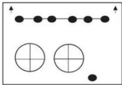
natural_image
Simple diagram with dots and circles, no text or symbols presentKLIMAGERÄT WANDSCHABLONE
SCHRAUBEN, 7 STK. (5,0 x 60 mm)
WANDDÜBEL, 7 STK. (8 x 40 mm)
natural_image
Two overlapping rectangular shapes with no text or symbolsnatural_image
Simple line drawing of a diagonal line with no text or symbolsWANDHALTERUNG
natural_image
Two identical screw fasteners with threaded spines and base plates (no text or symbols)BLECHSCHRAUBE, 2 STK. MONTAGEWINKEL (3,9x10 mm)
natural_image
Simple line drawing of a metal bracket with two circular holes (no text or symbols)INSTALLATION
natural_image
Simple diagram with three circles and a horizontal bar, no text or symbols presentWASSERWAAGE
natural_image
Simple line drawing of a handheld electric tool (no text or symbols)BOHRMASCHINE
natural_image
Simple geometric diagram showing a circle inscribed in a square with an additional tangent line (no text or symbols)BANDMASS 180 mm KERNBOHRER
natural_image
Simple line drawing of a rectangular object with three parallel lines and a protruding shaft (no text or symbols)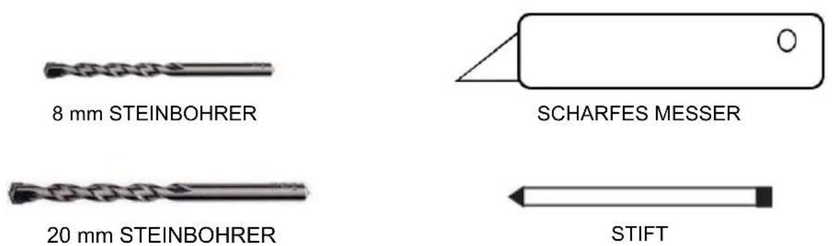
natural_image
3D diagram showing a vertical structure with a rectangular base and a grid-patterned floor, no text or symbols present.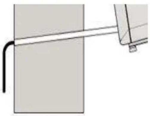
natural_image
Pure mechanical diagram showing a pipe or rod passing through a rectangular block (no text or symbols)natural_image
Diagram showing two white oval shapes on a brick wall with a ruler above them (no text or symbols)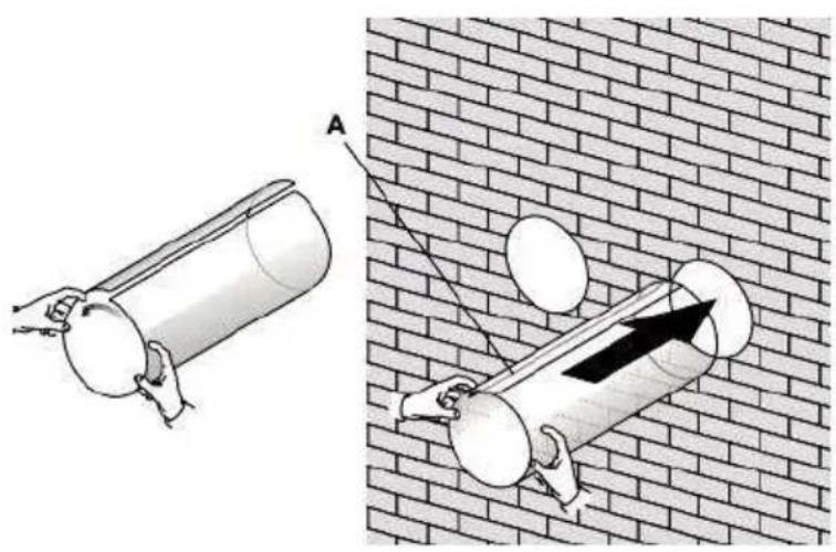
natural_image
Illustration of two cylindrical objects with handles hanging against a brick wall, one labeled A (no text or symbols present)natural_image
Illustration of two metal buckets on a brick wall, no text or symbols presentnatural_image
Illustration of a hand using a tool to install a brick wall corner, showing structural components and a magnified view (no text or symbols)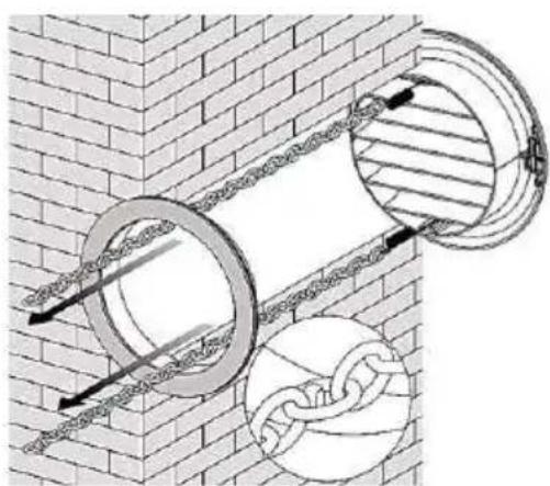
natural_image
Diagram of two circular pipe fittings embedded in a brick wall, with chains attached (no text or symbols)natural_image
Diagram of a brick wall with two circular pipe fittings and a magnified inset showing internal structure (no text or symbols)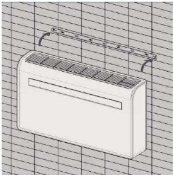
natural_image
Line drawing of a white air conditioner unit on a grid background, no text or symbols present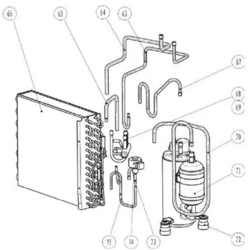
ERSATZTEILLISTE
Read the user manual

Read the operating instructions

Read the technical manual
Disposal
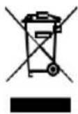
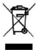
The crossed-out bin symbol requires the separate disposal of waste electrical and electronic equipment (WEEE). Electrical and electronic equipment may contain hazardous and environmentally hazardous substances. Therefore, do not dispose of it in unsorted residual waste, but designated collection point for waste electrical and electronic equipment.
This helps to protect resources and the environment.
For more information, contact your dealer or the local authorities.
Disposal of the Batteries
The crossed-out bin symbol requires the separate disposal of batteries. Please dispose the batteries in an environmentally friendly way. DO NOT dispose batteries in the residual waste. Please use the return and collection systems in your area or contact your dealer.

Declaration of Confirmity
We hereby confirm that this article complies with the essential requirements, regulations and directives of the EU.
The detailed declaration of conformity can be viewed at any time under the following link: www.becool.at/downloads
IMPORTANT!
AIR CONDITIONERS MUST ALWAYS BE STORED AND TRANSPORTED UPRIGHT, OTHERWISE IRREPARABLE DAMAGE MAY BE CAUSED TO THE COMPRESSOR; IF IN DOUBT WE SUGGEST WAITING AT LEAST 24 HOURS FOLLOWING INSTALLATION BEFORE STARTING THE UNIT.
- Carefully read the instructions before installing and/or operating the unit.
- This appliance is for indoor use only.
- This unit must be only connected to a 220-240 V / 50 Hz earthed outlet.
- Installation must be in accordance with regulations of the country where the unit is used.
- If you are in any doubt about the suitability of your electrical supply have it checked and, if necessary, modified by a qualified electrician.
- Disconnect the power from the appliance before dismantling, assembling or cleaning.
- Avoid touching any moving parts of the appliance.
- Never put fingers or any other objects through the fan guards when the product is running
- This appliance can be used by children aged from 8 years and above and persons with reduced physical, sensory or mental capabilities or lack of experience and knowledge if they have been given supervision or instruction concerning use of the appliance in a safe way and understand the hazards involved. Children shall not play with the appliance. Cleaning and user maintenance shall not be made by children without supervision.
BE COOL
- Do not leave children unsupervised with this appliance.
- Do not clean the unit by spraying it or immersing it in water.
- Never connect the unit to an electrical outlet using an extension cord. If an outlet is not available, one should be installed by a qualified electrician.
- Do not operate the unit unless it has been fully installed following the guidance provided within this manual.
- Never operate this appliance if the cord or plug is damaged. Ensure the power cord is not stretched or exposed to sharp objects/edges.
- If the supply cord is damaged, it must be replaced by the manufacturer, its service agent or similarly qualified persons in order to avoid a hazard.
- To remove the plug from the plug socket, pull the plug. Do not pull the power cord.
- Any service other than regular cleaning or filter replacement should be performed by an authorised service representative. Failure to comply could result in a voided warranty.
- Do not use the appliance for any purpose other than its intended use.
- Avoid restarting the air conditioner unless 3 minutes have passed since being turned off. This prevents damage to the compressor.
- The appliance should not be installed in laundry or wet rooms.
- The appliance must be installed in a room without sources of ignition (for example: open flames, an operating gas appliance or an operating electric heater).
- The unit must be installed on a solid vertical wall by a competent person. The electricity supply must only be connected after installation is complete.
• R290 refrigerant gas complies with European environmental directives.
• R290 has a low GWP (Global Warming Potential) of 3. - The air conditioner contains about 290 g of R290 refrigerant gas.
- Do not install or store in an unventilated space with an area smaller than 15 m2 per unit. The room must be such as to prevent stagnation of possible leaks of refrigerant gas as there could be a danger of fire or explosion hazard should the refrigerant come into contact with electric heaters, stoves or other sources of ignition.
- If the appliance is installed, used or stored in an unventilated room, the room must be such as to prevent stagnation of possible leaks of refrigerant gas as there could be a danger of fire or explosion should the refrigerant come into contact with electric heaters, stoves or other sources of ignition.
- Refrigerant gas may be odourless.
- Do not use the product and contact the retailer for advice, if damage has occurred to the unit which may have compromised the refrigerant system.
BE COOL
- Any repairs or maintenance must only be carried out on the unit by a suitably qualified engineer. Before opening and servicing the unit the authorized engineer must be in possession of a copy of the manufacturer's service manual and must follow the safety information contained within it to ensure all hazards are minimized.
- The refrigerant system should not be perforated or punctured.
- Do not cover or restrict the airflow from the outlet or inlet grills.
- Keep the filters clean. Under normal conditions, filters should only need cleaning once every three weeks (approximately). Since the filters remove airborne particles, more frequent cleaning maybe necessary, depending on the air quality.
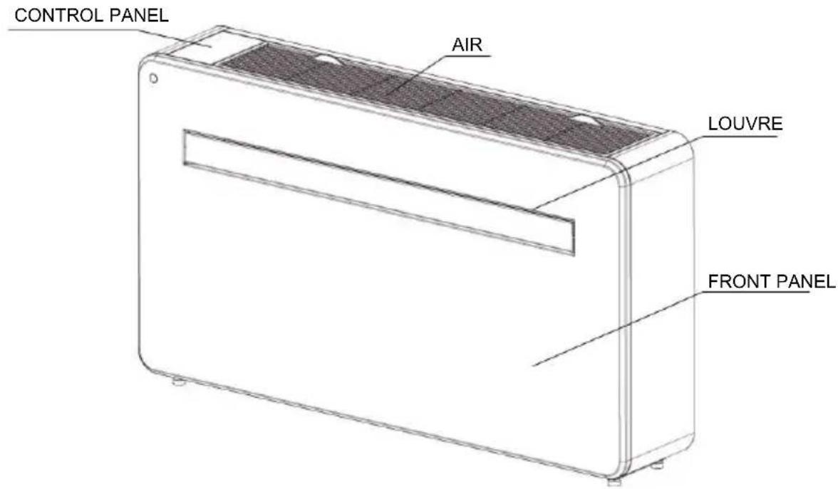
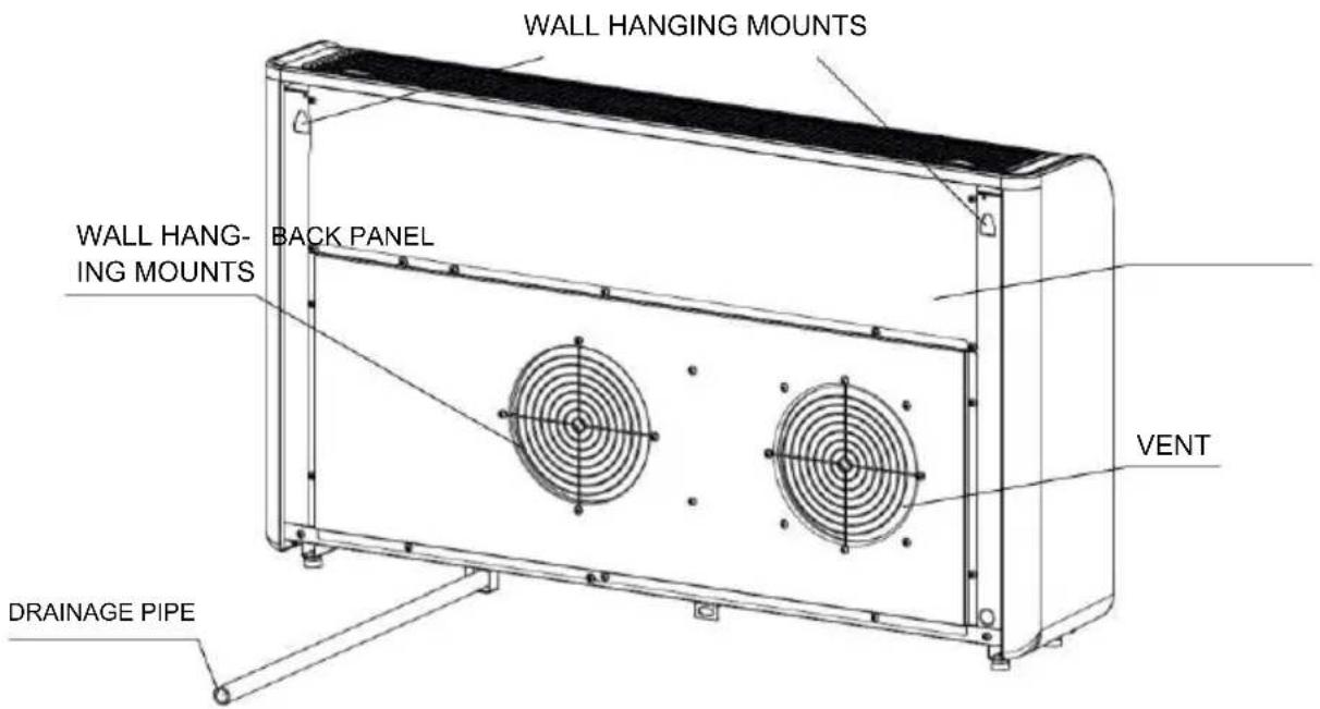
PRODUCT OVERVIEW
PRODUCT DIAGRAM
FRONT
BACK
BE COOL
FEATURES
- Simple operation.
- Self-evaporative function with energy saving technology.
- Sleek design that seamlessly fits into any style home.
- Bright LED screen-indicates temperature and current mode.
- On / off timer function-allows you to choose when the unit operates.
- WIFI App control providing additional functionality.
- Three fan speeds.
• Four modes to suit your every need including : Cooling / Heating / Fan / Dry - Silent running option, perfect for a restful night sleep.
WHATS INCLUDED
(DIAGRAMS FOR ILLUSTRATIVE PURPOSES ONLY)
natural_image
Line drawing of a rectangular electronic device with a recessed top and side slots (no text or symbols)AIR CONDITIONER
natural_image
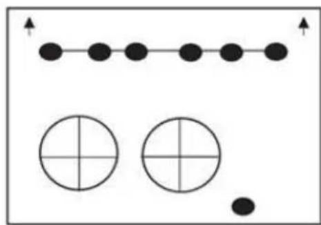
Simple diagram with dots and circles, no text or symbols presentWALL TEMPLATE
7PCS SCREWS (5.0 x 60mm)
7PCS WALL PLUGS
(8 x 40mm)
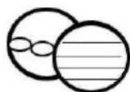
VENT COVER ASSEMBLY (X2)
(CHAIN, INDOOR RING
AND OUTDOOR COVER)
natural_image
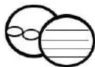
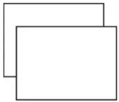
Two overlapping rectangular shapes with no text or symbolsPLASTIC DUCTING SHEET (X2)
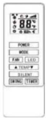
REMOTE CONTROL
natural_image
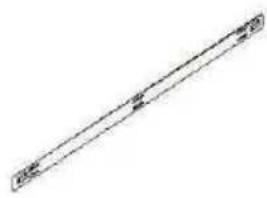
Simple line drawing of a diagonal line with two small markers at the ends (no text or symbols)WALL BRACKET
natural_image
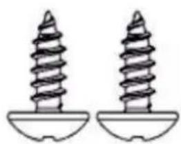
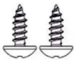
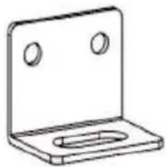
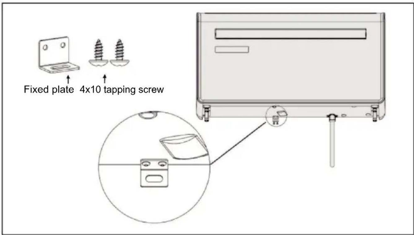
Two identical screwdrivers with threaded spines and base plates (no text or symbols)2PCS TAPPING SCREW FIXED PLATE (3.9x10mm)
natural_image
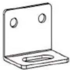
Simple line drawing of a metal bracket with two circular holes (no text or symbols)INSTALLATION
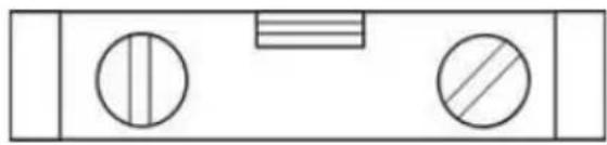
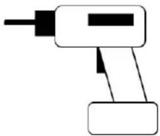
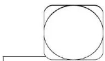
TOOLS REQUIRED
natural_image
Simple diagram with three circles and a horizontal bar inside a rectangle (no text or symbols)SPIRIT LEVEL
natural_image
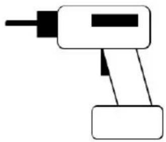
Simple line drawing of a handheld electric tool (no text or symbols)DRILL
natural_image
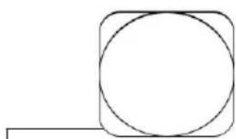
Simple geometric diagram showing a circle inscribed in a square with an additional line segment (no text or symbols)TAPE MEASURE 180mm CORE DRILL
natural_image
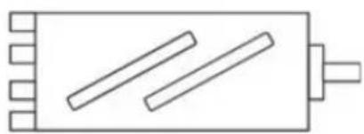
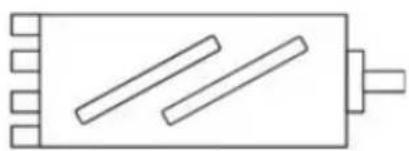
Simple line drawing of a rectangular object with three parallel lines and a protruding shaft (no text or symbols)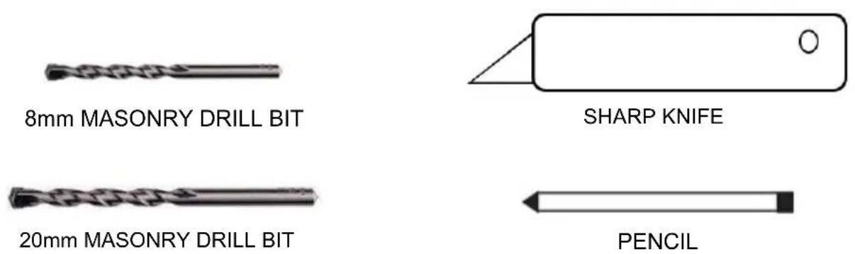
BEFORE STARTING INSTALLATION, PLEASE ENSURE YOU HAVE ALL SUITABLE EQUIPMENT AVAILABLE AND UNDERSTAND THE STEPS INVOLVED IN INSTALLATION. IF IN ANY DOUBT, PROFESSIONAL ADVICE SHOULD BE SOUGHT.
THE INSTALLER MUST ENSURE THAT THE PLANNED POSITION OF THE AIR CONDITIONER IS SUITABLE, AND THAT THERE ARE NO CABLES AND PIPES INSIDE THE WALL, AND NO OTHER OBSTRUCTIONS FIXED ON THE WALL, WHICH WOULD PRESENT A DANGER AND/ OR PREVENT COMPLETION OF INSTALLATION.
INSTALLATION
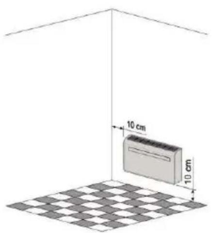
This unit must be installed on the main wall, as it vents directly out of its rear. and ensure the wall is flat, solid and reliable.
Leave at least 10 cm of space to the left, right and base of the machine. At least 20cm of space must be left above the unit to help air flow smoothly and stay away from curtains, plants, faucets, furniture and others appliances etc.
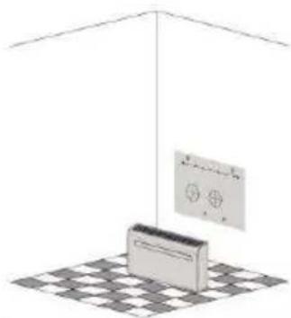
Paste the supplied installation template paper in position on the wall, ensuring that the reference line is level using a spirit level.
natural_image
3D diagram of a ceiling-mounted air conditioner unit with a grid floor and control panel (no text or symbols)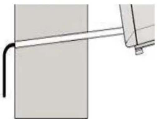
natural_image
Pure mechanical diagram showing a pipe or rod passing through a rectangular block (no text or symbols)The hole for the drainage pipe must be drilled using a 20mm Drill bit.
Ensure the hole is at a downward angle (min 5 degrees) so that the water will drain correctly.
Use a 180mm core drill to drill the two holes for the units ventilation, ensuring that both the holes are aligned with the template.
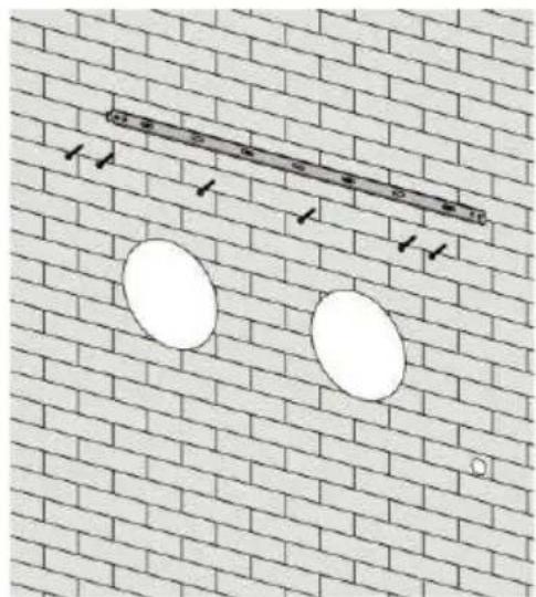
Use the template to mark the position of the screws for the hanging rail, using a spirit level to ensure it is straight and level.
Drill the marked holes using a suitable 8mm drill bit and insert wall plugs.
Line the hanging rail with the holes, and fix the rail into position using the supplied screws.
Ensure that the hanging rail is securely fastened onto the wall, and that there is no risk of the unit tipping or falling.
natural_image
Diagram showing two white oval shapes on a brick wall with a ruler above them (no text or symbols)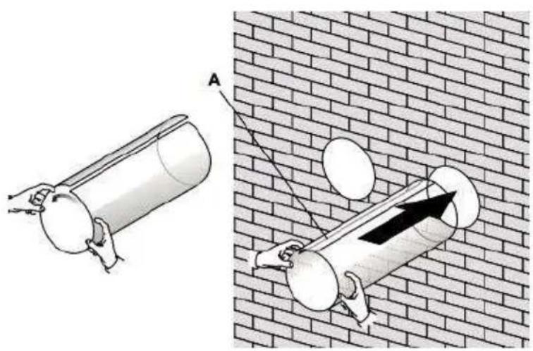
natural_image
Illustration of two cylindrical objects with handles hanging against a brick wall, one with an arrow indicating force or movement (no text or symbols present)Roll the plastic vent sheets into a tube and feed them from the inside into the holes previously made. Ensure the tubes sit flush to inside the wall.
natural_image
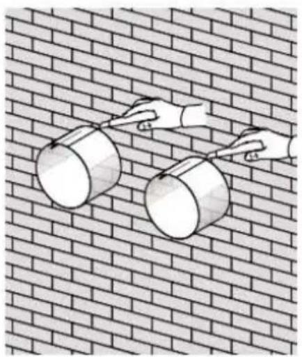
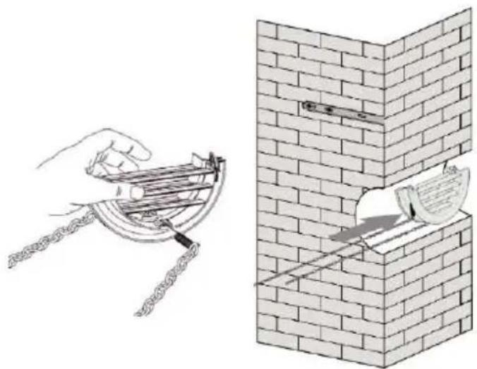
Illustration of two metallic buckets on a brick wall, no text or symbols presentTrim off the excess vent tube using a sharp knife, keeping the edge as neat as possible.
Insert the indoor fixing ring from the vent cover onto the indoor side of the air vent. Then fold the external vent cover in half. Attach the chains to each side of the vent cover, before sliding the cover outside through the vent hole.
natural_image
Illustration of a hand using a tool to clean or install a brick wall corner, with no text or symbols present.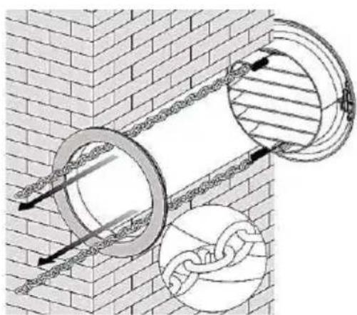
natural_image
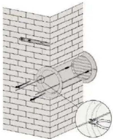
Diagram of two circular pipe fittings embedded in a brick wall, with chains and a spherical object nearby (no text or symbols)Expand the external cover, before tightly fixing the chains by hooking onto the indoor fixing ring. This will hold the external cover firmly in position. Repeat for the second vent.
Once the chains are fitted and secure, any excess chain should be removed by cutting the chain.
natural_image
Diagram of a brick wall with two circular pipe fittings and a magnified inset showing internal structure (no text or symbols)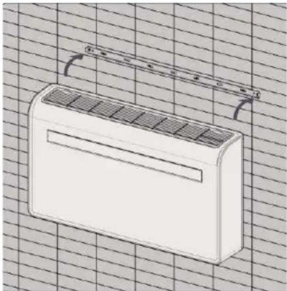
natural_image
Line drawing of a white air conditioner unit on a grid background (no text or symbols)Lift the unit onto the wall, align the hanging holes with the hooks on the hanging rail and gently rest the unit into place. At the same time, slide the drain pipe through the drainage hole.
NOTE:
1st: please ensure that the backside of product is tightly attached on the wall to avoid additional vibration and noise.
2nd : The end of the external water pipe must be placed in an open space or drain. Avoid damage or constriction to the drainage pipe to ensure the unit drains.
OPERATION
CONTROL PANEL
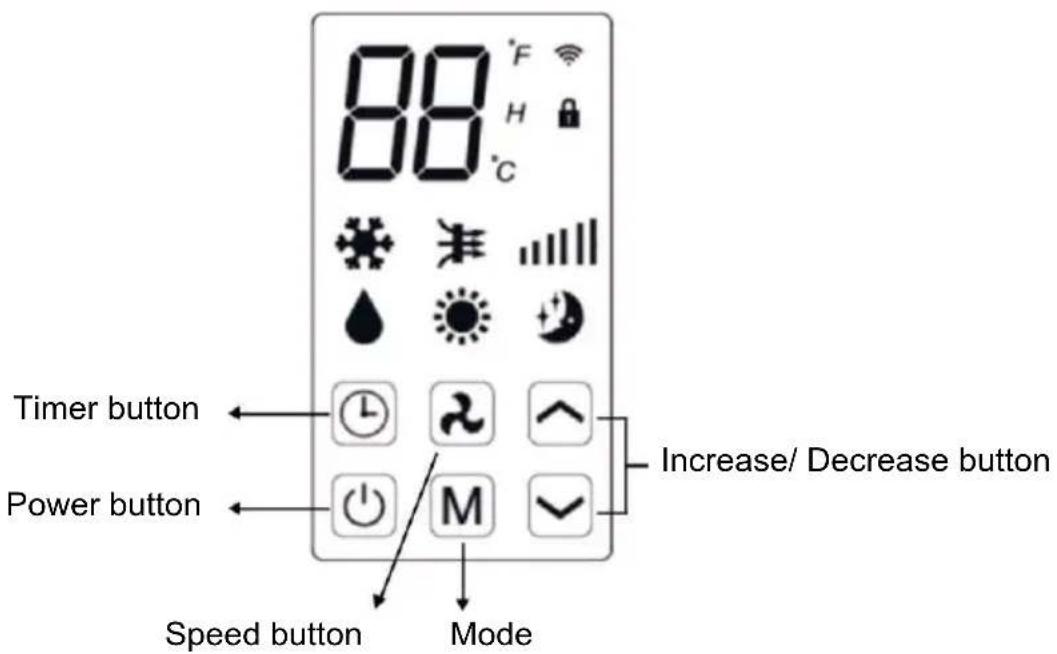
| Symbols indicated | Status |
 | Digital Display |
 | WIFI function |
 | Child lock |
 | Cooling function |
 | Fan function |
 | Dry function |
 | Heating function |
 | Silent function |
 | Speed function |
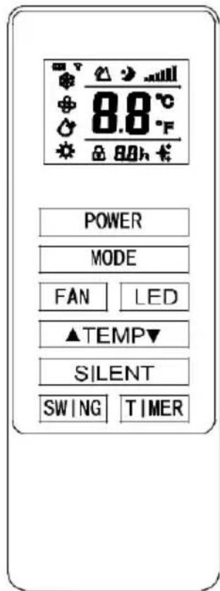
REMOTE CONTROL
The air conditioner can be controlled with the remote control. Two AAA-batteries (not include) are required.
NOTE: Further details of the functions can be found on the following page.
| POWER | Press the POWER button to turn the machine on or off. |
| MODE | Press the MODE button to select between cooling, heating, fan and dry modes. |
| FAN | Press the FAN button to change between high, medium and low fan speeds |
| LED | Press the LED button to open or close the LED background light of unit, it can be a choice for sleep condition. |
| Press the UP button to increase the desired temperature or timer duration | |
| Press the DOWN button to decrease the desired temperature or timer duration | |
| SILENT | Press it for silent mode, In Silent mode, noise will be lower, fan works in low speed. |
| SWING | Press to turn the louver swing function on and off (only activated by the remote control & APP) |
| TIMER | press the TIMER button to set the automatic switch-on/off |
FUNCTIONS
 POWER POWER | Press “POWER” to turn the unit On or Off. |
 MODE MODE | Press to change between the 4 different modes. The display will show the symbol for the mode currently selected. |
| MODE | COOLING | The cooling function allows the air conditioner to cool the room and at the same time reduces air humidity. The desired temperature can be adjusted using the increase and decrease button between 16°C and 30°C. The fan speed can also be adjusted using the speed button. |
| DRY | Dry mode will extract moisture from the air, which will be drained outside using the installed drain pipe. the fan speed and the desired temperature cannot be adjusted in dry mode. | |
| FAN | In fan mode the appliance will recirculate the air within the room, and will not cool, heat or dehumidify. The fan speed can be adjusted using the Speed button, But the desired temperature can not be set. | |
| HEATING | The heating function allows the air conditioner to heat the room. The desired temperature can be adjusted using the increase and decrease button between 16°C and 30°C. The fan speed can also be adjusted using the speed button. | |
| SILENT | Silent mode can be activated from APP or the remote control, It can also be activated by pressing "☐" + " ☐ on unit control panel at the same time. It will only operate in cooling or heating modes, the fan speed will change to low and noise will be lower. | |
| VITESSE DU VENTILATEUR | Press to change the fan speed between Low, Medium and High. The fan speed cannot be adjusted in Dry or Silent modes. | |
| TIMER | The air conditioner contains a 24 hour timer, which can be used to either set a delayed start, or a set period of operation. | |
| SHUTDOWN TIMER:While the unit is running press the timer button, the display will flash “0” 5 times, then press the up and down buttons to adjust the duration in 1 hour increments between 1 to 24 hours. When the timer has elapsed, the unit will shutdown automatically. | ||
| DELAYED START TIMER:With the unit in standby, press the timer button, the display will flash “0” 5 times. then press the up and down buttons to adjust the duration in 1 hour increments between 1 to 24 hours. After the timer has elapsed, the unit will start up in the same mode with the same settings as when it was turned off. | ||
| MODE |  COOLING COOLING | The cooling function allows the air conditioner to cool the room and at the same time reduces air humidity. The desired temperature can be adjusted using the increase and decrease button between 16°C and 30°C. The fan speed can also be adjusted using the speed button. |
 DRY DRY | Dry mode will extract moisture from the air, which will be drained outside using the installed drain pipe. the fan speed and the desired temperature cannot be adjusted in dry mode. | |
 FAN FAN | In fan mode the appliance will recirculate the air within the room, and will not cool, heat or dehumidify. The fan speed can be adjusted using the Speed button, But the desired temperature can not be set. | |
 HEATING HEATING | The heating function allows the air conditioner to heat the room. The desired temperature can be adjusted using the increase and decrease button between 16°C and 30°C. The fan speed can also be adjusted using the speed button. | |
 SILENT SILENT | Silent mode can be activated from APP or the remote control, It can also be activated by pressing "①"+" on unit control panel at the same time. It will only operate in cooling or heating modes, the fan speed will change to low and noise will be lower. | |
 VITESSE DU VENTILATEUR VITESSE DU VENTILATEUR | Press to change the fan speed between Low, Medium and High. The fan speed cannot be adjusted in Dry or Silent modes. | |
 TIMER TIMER | The air conditioner contains a 24 hour timer, which can be used to either set a delayed start, or a set period of operation. | |
| SHUTDOWN TIMER:While the unit is running press the timer button, the display will flash “0” 5 times, then press the up and down buttons to adjust the duration in 1 hour increments between 1 to 24 hours. When the timer has elapsed, the unit will shutdown automatically. | ||
| DELAYED START TIMER:With the unit in standby, press the timer button, the display will flash “0” 5 times, then press the up and down buttons to adjust the duration in 1 hour increments between 1 to 24 hours. After the timer has elapsed, the unit will start up in the same mode with the same settings as when it was turned off. | ||
| INCREASE AND DECREASE | Used within cooling and heating modes to adjust the desired temperature16-30°C. Also used while setting the timer to adjust the duration. | |
| SWING MODE | After machine turns on, press the “SWING” button, louver will swing continuously up and down; by pressing the button again the movement will stop and the louver remain in that position. Swing mode can only be adjusted from the remote, and will initially be turned on by default. the louver will close automatic once switch OFF the product. | |
| COMPRESSOR PROTECTION | There is a 3 minutes delay on power on. In order to protect the life of the compressor and electronic components please do not switch on the unit for at least 5 minutes after you turned the unit off. | |
WIFI SETUP AND SMART FEATURES
WIFI SETUP
BEFORE YOU START
- Ensure your router provides a standard 2.4ghz connection.
- If your router is dual band ensure that both networks have different network names (SSID). The provider of your router / Internet service provider will be able to provide advice specific to your router.
- Place the air conditioner as close as possible to the router during setup.
- Once the app has been installed on your phone, turn off the data connection, and ensure your phone is connected to your router via WIFI.
DOWNLOAD THE APP TO YOUR PHONE
Download the "SMART LIFE" app, from your chosen app store, using the QR codes below, or by searching for the app in your chosen store.

CONNECTION METHODS AVAILABLE FOR SETUP
The air conditioner has two different setup modes, Quick Connection and AP connection (Access Point). The quick connection is a quick and simple way to set the unit up. The AP connection uses a direct local WIFI connection between your phone and the air conditioner to upload the network details.
In Standby mode press and hold the speed button for 3 seconds (until you hear a bleep) to enter the wifi connection mode.
Please ensure your device is in the correct wifi connection mode for the connection type you are attempting, the flashing of the wifi light on your air conditioner will indicate this.
| Connection Type | Frequency of Flashes |
| Quick Connection | Flashes twice per second |
| AP Connection (Access Point) | Flashes once per three seconds |
CHANGING BETWEEN CONNECTION TYPES
To change the unit between the two wifi connection modes, hold the Speed button for 3 seconds.
REGISTER THE APP
1. Press on the register button at the bottom of the screen.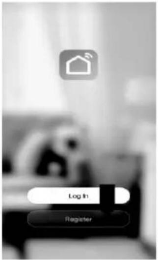 | 2. Read the Privacy policy and press the Agree Button.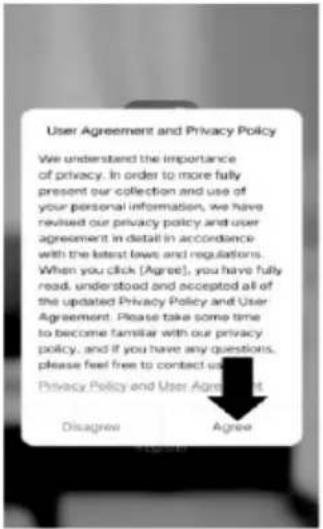 | 3. Enter your email address or phone number and press continue to register.<RegisterUnited KingdomEmail### User Agreement and Privacy Policy |
4.A verification code will be sent by the method selected in step 3. Enter the code into the app.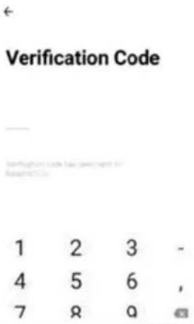 | 5.Type in the password you would like to create. This needs to be 6-20 characters, with letters and numbers.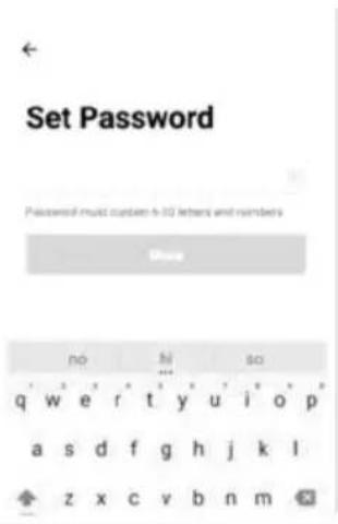 | 6.The app is now registered. It will automatically log you in following registration.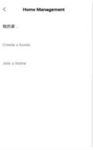 |
SETTING UP YOUR HOME WITHIN THE APP
"SMART LIFE" is designed so it can work with a large number of compatible smart devices within your home. It can also be set up to work with multiple devices within different houses. As such during the setup process, the app requires that different areas are created and named to allow easy management of all your devices. When new devices are added, they are assigned to one of the rooms you have created.
CREATING ROOMS
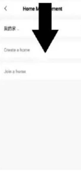 | 1. Press on the create a home button.2. Type in a name for your home.3. Press “home location” button to select the location of your home. (See SETTING YOUR LOCATION below)4. New rooms can be added by pressing the ADD ROOM option at the bottom. (See ADD ANOTHER ROOM below).And untick any rooms that are not required on the app, then Press SAVE in the top right corner. | 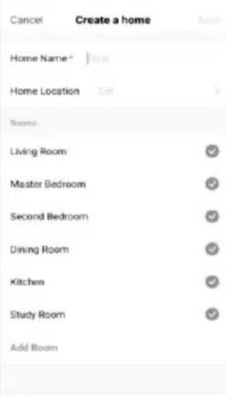 |
Use your finger to move the orange HOME symbol.
When the symbol is in the approximate location of your home, press the confirm button in the top right corner.
ADD ANOTHER ROOM
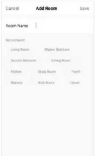
Type in the name of the room, and press Done in the top right corner.
CONNECTING USING QUICK CONNECTION
Before initiating the connection, make sure the unit is in standby mode, with the WIFI light flashing twice per second. If not follow the instructions for changing the connection mode. Also ensure your phone is connected to the wifi network. (We advise turning mobile data off during setup)
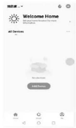
- Open app and press "+" to add device, or use the add device button.
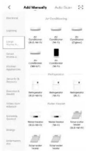
- Select the type of device as "Large Home Appliance"
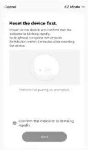
- Ensure the WIFI light on the air conditioner is flashing twice per second, then click NEXT button to enter the next setting.
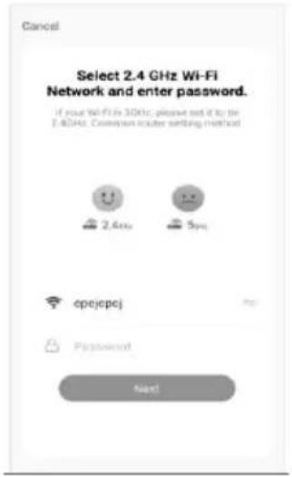 | 4. Connect a WIFI and enter the password.5. Click NEXT button to scan and connect a new device. Waiting for this process to complete.6. Please retry if this fails. please review the trouble-shooting section for further help if still unsuccessful | 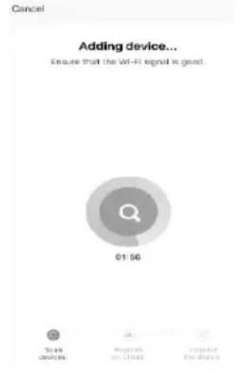 |
CONNECTING USING AP MODE (ALTERNATIVE METHOD)
Before initiating the connection, make sure the unit is in standby mode, with the wifi light flashing once per second. If not follow the instructions for changing the wifi connection mode. Also ensure your phone is connected to the wifi network. (We advise turning mobile data off during setup)
| 1)Open app and press “+” to add device, or use the add device button. | 2)Select the type of device as “Large Home Appliance” | 3)Change to the AP mode in the top right of the screen. |
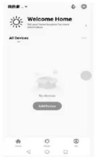 | 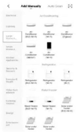 | 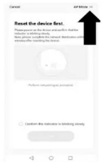 |
4) Ensure the wifi light on the air conditioner is slowly flashing (once per three seconds), then click NEXT button to enter the next setting.
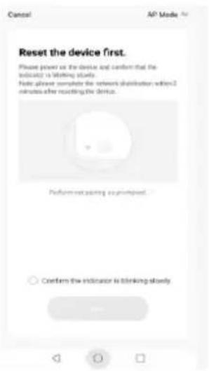
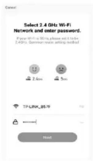
Enter your wifi password and press confirm.
6) Get into network settings in your phone and connect to the "Smart Life xxx" connection. There is no password to enter. Then return back to the app to complete setup.
Connect your mobile phone to the device's hotspot
- Please connect your phone to the hotspot shown below
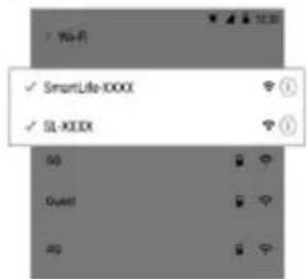
- Return to this app and continue adding devices
Once the connection process has completed, go back to the network settings on your phone to ensure your phone has reconnected to your wifi router.
CONTROLLING YOUR DEVICE THROUGH THE APP THE HOME SCREEN
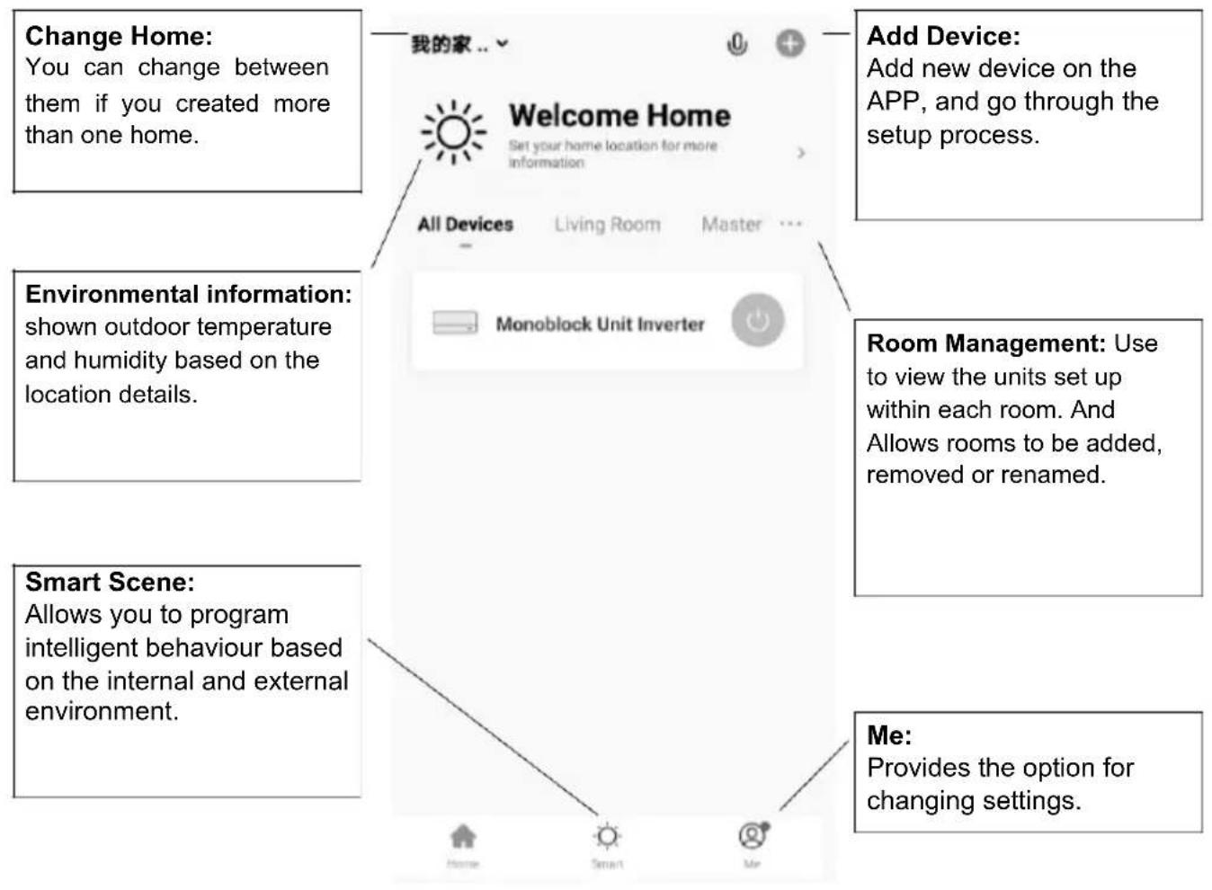
Each device has its own entry on the home screen to allow the user to either quickly turn the unit on or off, or to enter the device screen to make other changes.
DEVICE SCREEN
Name of Air
Conditioner: Click to enter the Device Screen.
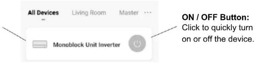
ON / OFF Button:
Click to quickly turn on or off the device.
DEVICE SCREEN
The device screen is the main control screen for the air conditioner, providing access to the controls to amend the functions and settings.
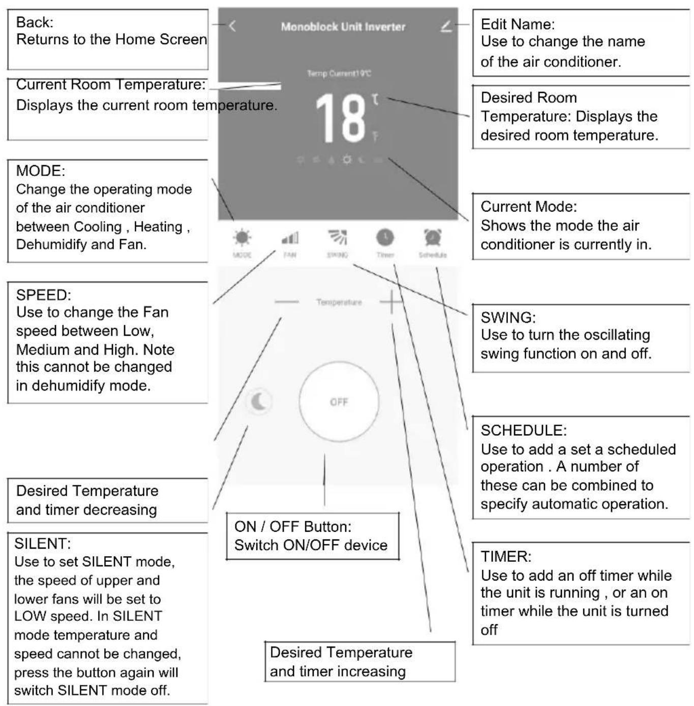
Due to continuous development of the app, the layout and available features may be subject to change.
SMART SCENES
Smart Scenes is a powerful tool providing the option to customise the operation of the air conditioner based both on conditions within the room and outside influences. This gives the user the option of specifying much more intelligent actions. These are split into two categories Scene and Automation.
SCENE
Scene allows for a one touch button to be added to the Home screen. The button can be used to change a number of settings in one go, and can change all the settings within the unit. A number of scenes can easily be setup, allowing the user to easily change between a number of preset configurations.
Below is an example of how to set up a scene:
| 1.Press on the Smart Scene tab at the bottom of the Home screen. | 2.Press on the Plus in the top right corner to add a smart scene. | 3.Press on the Launch Tap-to-Run to create a new Scene. |
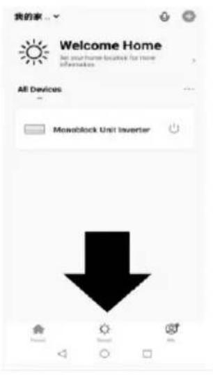 | 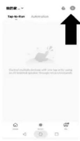 | 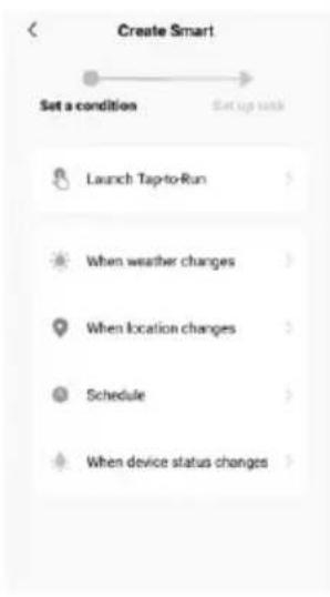 |
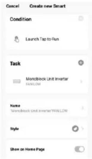
- Press the arrow next to "Name" to input the name for your Scene
Show on Home Page: Leave this on if you require the scene to be displayed as a button on the Home Screen
Press the Blue Plus to add the action required. Then select the air conditioner from the list of devices.
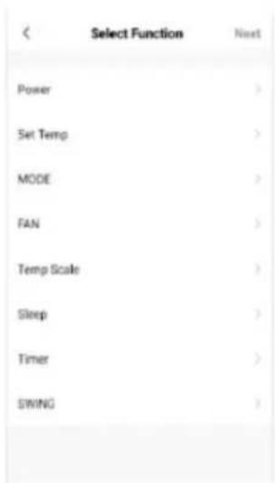
- Chose the function, set the value for the function, and then press the arrow button in the top left corner, to return to the previous screen.
6.Once all the functions required have been added, press the Save button in the top right corner to finalise and save your new Scene.
AUTOMATION
Automation allows an automatic action to be set up for the device. This can be triggered by the Time, indoor temperature, humidity of the room, weather conditions, and a range of other influences.
- Press on the Smart Scene tab at the bottom of the Home screen.
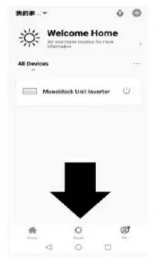
- Press on the Plus in the top right corner to add a smart scene.
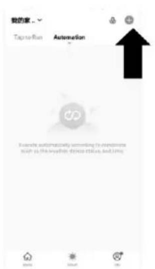
3.ress on the Launch Tap-to-Run to create a new Scene.
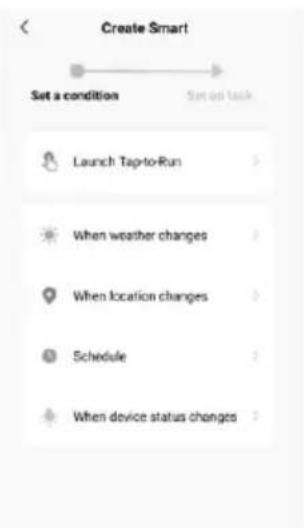
- Setup is very similar to the scene setup on the previous page, and includes an extra section for specifying a trigger for the scene to start. Press the arrow next to "Name" to input the name for your Scene Show on Home Page: Leave this on if you require the scene to be displayed as a button on the Home Screen Press the Blue Plus to add the action required. Then select the air conditioner from the list of devices.
- Chose the function, set the value for the function, and then press the arrow button in the top left corner, to return to the previous screen.
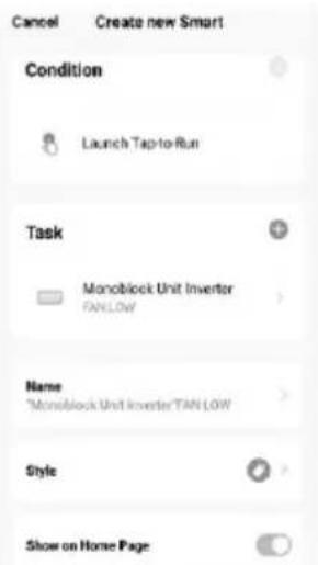
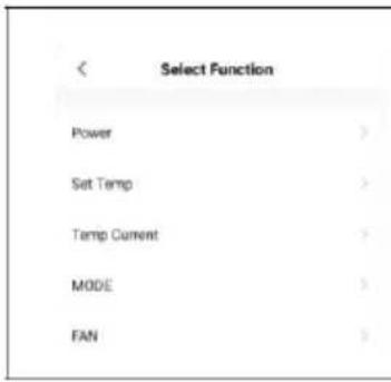
- Chose the function, and then press the arrow button in the top left corner, to return to the previous screen.
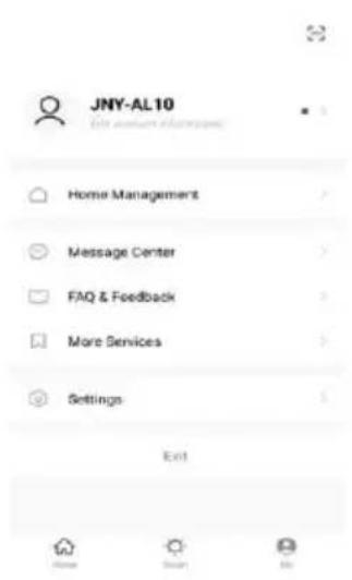
ME
The profile tab gives you the option to edit both your detail, and use the added features of the unit.
CHANGING THE NAME OF YOUR DEVICE
When in any of the device screens further settings for the device can be accessed, by pressing on the three dots in the top right hand corner. The top option within this allows you to change the name of the device to something relevant to the use of the product, such as "Living Room Air Conditioner". Within the menu, you also have the option of setting up a pattern lock or change your password.
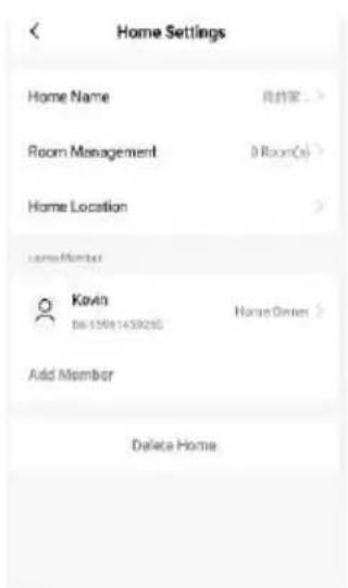
DEVICE SHARING
This allows you to share access to the controls of your air conditioner with friends and family.
In page "Home Management", select "My home", you could "Add Member" there to share access to the controls of your air conditioner with friends and family, pls refer to the left picture.
INTEGRATION
This allows the unit to be integrated with your favourite home automation hardware such as Google Home and the Amazon Echo.
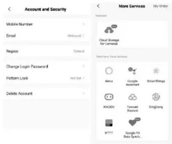
Select "More Services", you could integrate with third-party voice services, pls refer to the left picture.
TROUBLESHOOTING
Do not repair or disassemble the air conditioning. Unqualified repair will invalidate the warranty and may lead to failure, causing injuries and property damage. Only use it as directed in this user manual and only perform operations advised here.
| Problem | Reasons | Solutions |
| The air conditioner does not work | There is no electricity. | Check the unit is plugged in, and the socket is working normally. |
| In cooling mode, the room temperature is lower than the desired temperature; in heating mode, the room temperature is higher than the desired temperature. | Adjust the desired room temperature. | |
| In dehumidification (dry) mode, the ambient temperature is low. | Ensure that the room temperature is above 17°C for dry mode. | |
| There is direct sunlight. | Use curtains to reduce heat from the sun. | |
| The cooling or heating effect is poor | Doors or windows are open. | Close doors and windows. |
| The filters screen is dirty. | Clean or replace the filter screen. | |
| The air inlet or outlet is blocked. | Clear obstructions; make sure the unit is installed as per the instructions. | |
| The air conditioner is leaking. | The unit is not straight. | Use a spirit level to check the unit is horizontal, if not remove from the wall and Straighten. |
| The drain pipe is blocked. | Check the drain pipe to ensure it is not blocked or constricted. | |
| Compressor does not work. | Overheat protection operational. | Wait for 3 minutes until the temperature is lowered, and then restart the machine. |
| The remote control does not work. | The remote control is not aligned with the direction of the remote-control receiver. | Let the remote control get close to the air conditioner, and make sure that the remote control directly faces to the direction of the remote-control receiver. |
| Batteries poor. | Replace batteries. |
If problems not listed in the table occur or recommended solutions do not work, please contact the service centre.
ERROR CODES
| Fault Code | Fault Description | Fault Code | Fault Description |
| F1 | Compressor IPM error | P5 | AC undervoltage protection |
| F2 PFC/IPM error | P7 Defrost protection on coil tube | ||
| F3 | Compressor start error | P8 | Zero-crossing fault detection |
| F4 Compressor running out of step | PA | Return air sensor temperature abnormal protection | |
| F5 | Location detection loop failure | PE | Abnormal refrigerant circulation |
| F6 PCB communication error | PH Exhaust temperature protection | ||
| F8 | Sensor on suction pipe error | E0 | Sensor on suction pipe error |
| FA Phase current overcurrent protection | E1 Temperature sensor error | ||
| FL | Water-full protection | E2 | Sensor error on indoor coil tube |
| P1 | Over-heat protection on top of compressor | E3 DC fan Feedback failure | |
| P2 | Dc bus voltage Undervoltage protection | E5 | Water-splash motor error |
| P3 AC Input voltage protection | E8 Fan feedback fault | ||
| P4 | AC over-current protection | EE | EE error |
TECHNICAL DATA
| MODEL | BC10MBKL2101F |
| Capacity Cooling / Heating | 2930W/ 2350W |
| Rated Input Cooling / Heating | 1120W/745W |
| Rated current | 5.0A |
| Air Flow | 500m3/h |
| EER/COP | 2.6/3.1 |
| Fuse | T 15AH, 250V |
| Compressor | Rotary, 290g, R290 gas |
| Sound Power Level | 58dB (A) |
| Moisture removal | 24 L/Day |
| Maximum Allowable Pressure | 1,3/3,8 MPa |
| Power Supply | 220-240V / 50Hz |
| Net Weight | 42.5kg |
| Dimension (L*D*H) | 1000 x 200 x 585mm |
| Contact addresses for further information | Schuss Home Electronic GmbHScheringgasse 3, A-1140 ViennaTel: +43 (1) 97 0 21 – 0Service line: +43 (1) 97 0 21 – 502www.becool.atFB-Nr: 236974 t / FB-Court: Vienna |
TECHNICAL DRAWING
MODEL: BC10MBKL2101F
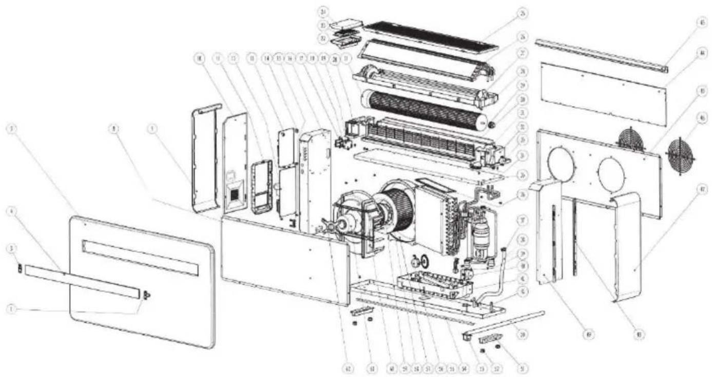
SPARE PARTS LIST
| 1 | Guide vane right fixed card | 22 | Display panel mounting box |
| 3 | Air deflector fixing part | 23 | Display light panel |
| 4 | Air deflector | 24 | panel mirror |
| 5 | The front panel | 25 | Filter |
| 8 | Front cover | 26 | Evaporator assembly |
| 9 | Left cover | 27 | Water pans |
| 10 | Electronic control box cover | 28 | Air supply wind turbines |
| 11 | Plastic electric control box | 29 | Rotor shaft sleeve |
| 12 | Variable frequency drive plate | 30 | Outlet guard |
| 13 | Main control panel | 31 | Air duct foam |
| 14 | Isolation column | 32 | The right base |
| 15 | Line pressing board | 33 | Stepper motor |
| 16 | The left support plate | 34 | Middle partition rubber |
| 17 | WIFI protection box cover | 35 | The partition |
| 18 | WiFi module | 36 | Torsion spring |
| 19 | WIFI protective box | 37 | Condenser cover |
| 20 | Left base | 38 | Water pipe |
| 21 | Plastic c sealed dc brushless motor | 39 | Water level switch |
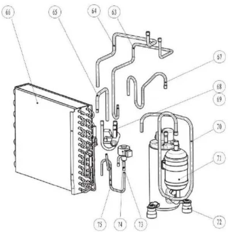
SPARE PARTS LIST
| 40 | Water release switch assembly | 58 | Exhaust wind turbines |
| 41 | Under water pans | 59 | Motor base (DC) |
| 42 | Base | 60 | Lower air duct 1 |
| 43 | Support bar | 61 | Plastic sealed dc brushless motor |
| 44 | The after cover plate | 62 | The motor bracket |
| 45 | Back panel | 63 | Electronic expansion valve nozzles1 |
| 46 | Rear protectin filter | 64 | Four way valve connection 2 |
| 47 | Right Left cover | 65 | Four way valve connection 1 |
| 48 | Right link bar | 66 | Condenser assembly |
| 49 | Light support plate | 67 | Compressor discharge pipe |
| 50 | Drain pipe | 68 | Four-way valve |
| 51 | Chassis stents | 69 | Four way valve coil |
| 52 | The rubber feet | 70 | Compressor sunction pipe |
| 53 | Water Management card | 71 | The compressor |
| 54 | Front strap | 72 | Compressor footing |
| 55 | Dc water drawing motor | 73 | Electronic expansion valve coil |
| 56 | Water wheel | 74 | Electronic expansion valve |
| 57 | Lower air duct 2 | 75 | Electronic expansion valve nozzles2 |
WARRANTY
By purchasing a BE COOL quality product you have acquired an innovative, long lasting and reliable item.
For this BE COOL device we grant a warranty of 2 years from the date of purchase, valid in Austria only.
In the unlikely event that service work is required on your device in this period we warrant free repair (spare parts and labour) or (subject to Schuss's decision) to replace the product. In the event that neither repair nor exchange make sense from an economical perspective we reserve the right to issue a credit based on current value.
When dealing with air conditioning devices you should always contact the customer hotline first (see label on the device or the title page of the instruction manual), in case of fans contact your dealer or us directly. Please note that repair not performed by the authorised workshop in Austria immediately renders this warranty void.
This warranty does not include:
• Repair of replacement of parts due to normal wear
• Damage due to non-compliance with the instruction manual
• Devices that are used commercially – even in part
• Devices damaged by external forces (falling, impact, cracking, improper use etc.) as well as aesthetic wear
• Devices that have been used improperly
• Devices that were not opened by our authorised workshop.
- Damages caused by improperly closed condensation drains on air conditioning devices or improperly inserted water container.
• Unfulfilled customer expectations.
• Damage caused by force majeure, water, lightning and overvoltage.
- Devices on which type denomination and/or serial number on the device have been erased, rendered illegible or removed.
- Service work not performed by our authorised workshops, transport costs to an authorised workshop or us and back as well as associated risks.
Please note that within the warranty period we charge a flat rate of 60 € (indexed as per consumer price index 2015, June 2020) in case of operating errors or if no fault can be found.
The total warranty period of 2 years is not extended if warranty service is performed (repair or device replacement).
The 2 year warranty is only valid if the original invoice (must contain name and address of the dealer as well as full device name) and the respective warranty certificate are produced, on which the device type and serial number (can be found on the box and the device's rear or bottom) are to be noted! Only the statutory warranty coverage applies if the warranty certificate cannot be produced!
Please note that the statutory warranty coverage is not altered by this warranty and that it applies in full regardless.
Schuss Home Electronic GmbH and its vicarious agents are only liable for damages in case of gross negligence or intent. Liability for loss of profit, expected but not incurred savings, consequential damages and damages from third party claims is excluded in any case. Damages to or for recorded data are always excluded from the liability for damages.
Congratulations on your choice. We hope you will enjoy using your BE COOL device!
ADDRESS
BE COOL Sales
Schuss Home Electronic GmbH
1140 Vienna, Scheringgasse 3
Tel.: +43 (0)1/ 970 21
Type designation:......
Serial number:
Together with the device, this warranty certificate must be handed to the authorised workshop or dealer you bought the device from in the event of a warranty claim!
NOTE
NOTE
- MONOBLOCK KLIMAGERÄT BC10MBKL2101F
- INSTALLATION
- IMPORTANT!
- BE COOL
- PRODUCT OVERVIEW
- PRODUCT DIAGRAM
- FEATURES
- WHATS INCLUDED
- NOTE:
- OPERATION
- CONTROL PANEL
- REMOTE CONTROL
- FUNCTIONS
- WIFI SETUP AND SMART FEATURES
- WIFI SETUP
- DOWNLOAD THE APP TO YOUR PHONE
- CONNECTION METHODS AVAILABLE FOR SETUP
- CHANGING BETWEEN CONNECTION TYPES
- REGISTER THE APP
- SETTING UP YOUR HOME WITHIN THE APP
- CREATING ROOMS
- CONNECTING USING QUICK CONNECTION
- CONNECTING USING AP MODE (ALTERNATIVE METHOD)
- Connect your mobile phone to the device's hotspot
- CONTROLLING YOUR DEVICE THROUGH THE APP THE HOME SCREEN
- DEVICE SCREEN
- Name of Air
- ON / OFF Button:
- SMART SCENES
- SCENE
- Below is an example of how to set up a scene:
- AUTOMATION
- ME
- CHANGING THE NAME OF YOUR DEVICE
- DEVICE SHARING
- INTEGRATION
- TROUBLESHOOTING
- TECHNICAL DRAWING
- WARRANTY
- For this BE COOL device we grant a warranty of 2 years from the date of purchase, valid in Austria only.
- This warranty does not include:
- ADDRESS
- NOTE
Brand : Be Cool
Model : BC10MBKL2101F
Category : Air conditioner