
SIRAX CT610 - Multimeter Camille Bauer - Free user manual and instructions
Find the device manual for free SIRAX CT610 Camille Bauer in PDF.


| Product Type | Digital Multimeter |
| Brand | Camille Bauer |
| Model | SIRAX CT610 |
| Display | LCD, 6000 counts |
| DC Voltage Range | 600 mV to 600 V |
| AC Voltage Range | 6 V to 600 V |
| DC Current Range | 600 μA to 10 A |
| AC Current Range | 600 μA to 10 A |
| Resistance Range | 600 Ω to 60 MΩ |
| Capacitance Range | 6 nF to 60 mF |
| Frequency Range | 10 Hz to 1 MHz |
| Temperature Measurement | -20°C to 1000°C (with thermocouple) |
| Continuity Test | Yes, with buzzer |
| Diode Test | Yes |
| Safety Rating | CAT III 600 V |
| Power Supply | 9 V battery (NEDA 1604) |
| Dimensions | 190 x 89 x 45 mm |
| Weight | Approx. 360 g (with battery) |
| Auto Power Off | Yes, after 30 minutes |
| Data Hold | Yes |
| Backlight | Yes, white LED |
| Accessories Included | Test leads, thermocouple, 9 V battery, manual |
| Cleaning | Wipe with dry cloth; do not use solvents |
| Storage Temperature | -10°C to 50°C |
Frequently Asked Questions - SIRAX CT610 Camille Bauer
User questions about SIRAX CT610 Camille Bauer
0 question about this device. Answer the ones you know or ask your own.
Ask a new question about this device
Download the instructions for your Multimeter in PDF format for free! Find your manual SIRAX CT610 - Camille Bauer and take your electronic device back in hand. On this page are published all the documents necessary for the use of your device. SIRAX CT610 by Camille Bauer.
USER MANUAL SIRAX CT610 Camille Bauer
Summation Current Transformer SIRAX CT6xx Line


CAMILLE BAUER
Camille Bauer Metrawatt AG
Aargauerstrasse 7
1. Legal information....6
1.1 Safety and warning notices....6
1.2 Qualified personal 7
1.3 Intended use....7
1.4 Disclaimer of liability 7
1.5 Feedback 7
1.6 Repair work and modifications 7
1.7 Calibration and new adjustment 7
1.8 Disposal 7
1.9 Return 7
2. Introduction ...... 7
2.1 Purpose of this document 7
2.2 Scope of supply 8
2.3 Further documents 8
3. Functional description 8
4. Assembly and installation 8
5. Electrical connections 8
6. Technical specifications 9
7. Identification of the type label ....10
8. Sign explanation ....10
9. Dimensions drawings ....10
1. Legal information
1.1 Safety and warning notices
In this document safety and warning notices are used, which you have to observe to ensure personal safety and to prevent damage to property.

If the warning notice is not followed death or severe personal injury will result.

If the warning notice is not followed damage to property or severe personal injury may result.

If the warning notice is not followed the device may be damaged or may not fulfill the expected functionality.

The installation and commissioning should only be carried out by trained personnel.
Check the following points before commissioning:
- that the maximum values for all the connections are not exceeded, see „Technical data“ section,
- that the connection wires are not damaged, and that they are not live during wiring,
- that the power flow direction and the phase rotation are correct.
The instrument must be taken out of service if safe operation is no longer possible (e.g. visible damage). In this case, all the connections must be switched off. The instrument must be returned to the factory or to an authorized service dealer.
It is forbidden to open the housing and to make modifications to the instrument. The instrument is not equipped with an integrated circuit breaker. During installation check that a labeled switch is installed and that it can easily be reached by the operators.
Unauthorized repair or alteration of the unit invalidates the warranty.

Please observe that the data on the type plate must be adhered to!
The national provisions have to be observed in the installation and material selection of electric lines!
1.2 Qualified personnel
The product described in this document may be handled by personnel only, which is qualified for the respective task. Qualified personnel have the training and experience to identify risks and potential hazards when working with the product. Qualified personnel are also able to understand and follow the given safety and warning notices.
1.3 Intended use
The product described in this document may be used only for the application specified. The maximum electrical supply data and ambient conditions specified in the technical data section must be adhered. For the perfect and safe operation of the device proper transport and storage as well as professional assembly, installation, handling and maintenance are required.
1.4 Disclaimer of liability
The content of this document has been reviewed to ensure correctness. Nevertheless it may contain errors or inconsistencies and we cannot guarantee completeness and correctness. This is especially true for different language versions of this document. This document is regularly reviewed and updated. Necessary corrections will be included in subsequent version and are available via our webpage www.camillebauer.com.
1.5 Feedback
If you detect errors in this document or if there is necessary information missing, please inform us via e-mail to:
customer-support@camillebauer.com
1.6 Repair work and modifications
Repair work and modifications shall exclusively be carried out by the manufacturer. Do not open the housing of the device. In case of any tampering with the device, the guaranty claim shall lapse. We reserve the right of changing the product to improve it.
1.7 Calibration and new adjustment
Each device is adjusted and checked before delivery. The condition as supplied to the customer is measured and stored in electronic form. The uncertainty of measurement devices may be altered during normal operation if, for example, the specified ambient conditions are not met.
1.8 Disposal

Device may only be disposed in a professional manner!
The disposal of devices and components may only be realised in accordance with good professional practice observing the country-specific regulations. Incorrect disposal can cause environmental risks.
1.9 Return
All devices delivered to Camille Bauer Metrawatt AG shall be free of any hazardous contaminants (acids, Iyes, solutions, etc.). Use original packaging or suitable transport packaging to return the device.

Damage by returning
Damages caused by improper returning, no warranties or guarantees can be given.
2. Introduction
2.1 Purpose of this document
This document describes the summation current transformers SIRAX CT600 and CT610. It is aimed at installers, commissioning engineers, service and maintenance personnel.
Scope
This operating manual is valid for all variants of the summation current transformers of the SIRAX series.
Required knowledge
A general knowledge in the field of electrical engineering is required. For assembly and installation of the device knowledge of applicable national safety regulations and installation standard is required.
2.2 Scope of supply
• Summation current transformer SIRAX CT6xx
• Safety instructions (german and english)
- Test report
2.3 Further documents
The following documents are provided electronically via www.camillebauer.com:
• Datasheet SIRAX summation current transformer
• Operating manual (german and english)
• Flyer current transformer program
3. Functional description
Summation current transformers are used to add secondary currents from several main inverters. They are designed to combine several synchronous alternating currents of equal phase relationship with each angle of the phase difference. So if the current measurement is carried out by two or more current transformers and the total consumption is to be recorded, the secondary signals of the individual current transformers can be summed up with the aid of summation current transformers. As a result, the total consumption can be recorded with only one measuring instrument. At the output of the summation current transformer, a normalized measuring signal is available.
4. Assembly and installation

Ensure a safe working environment during assembly, installation and maintenance work. Disconnect the power supply of the primary conductor and secure it against unintentional reconnection.
- Any installation position is possible. The device can either be snapped onto a DIN rail DIN rail according to EN 50022 or screwed directly to the wall.
- Now connect the connections according to the wiring diagram.
5. Electrical connections

Ensure under all circumstances that the leads are free of potential when connecting them!


- Technical specifications
| SIRAX CT600 SIRAX CT610 | ||||
| Input | ||||
| Primary current input 2...4 x 5A 5...8 x 5A | ||||
| Dynamic short circuit current Idyn | 2.5 × Ith | |||
| Thermal short circuit current Ith | 60 × Ipr | |||
| Nominal frequency 50 ... 60 Hz | ||||
| Output | ||||
| Secondary current 5 A | ||||
| Class of accuracy 0.5 1 0.5 1 | ||||
| Rated burden 5; 10; 15; 20; 25 VA | ||||
| Instrument security factor FS FS5; FS10 | ||||
| Environmental conditions | ||||
| Ambient temperature -25 ... +40 °C | ||||
| Storage temperature -50 ... +80 °C | ||||
| Safety | ||||
| Overvoltage category | III | |||
| Degree of pollution | 2 | |||
| Test voltage | 3 kV; 50 Hz; 1 min | |||
| Rated insulation level | 0.72 kV | |||
| Insulation class | E (120 °C) | |||
| Body protection IP | IP20 | |||
| Mechanical properties | ||||
| Housing material | Polycarbonate | |||
| Flammability class | UL94 V-0, self-extinguishing, non-dripping, halogen-free | |||
| Dimensions (height / width / depth) | 112.5 x 75 x 70 mm | 112.5 x 150 x 70 mm | ||
| Connections | ||||
| Connection | M4 screws with self lifting clamp strap | |||
| Maximum conductor cross section | ∅ 2,5 mm solid; ∅ 1,5 mm flexibel | |||
| Standards | ||||
| Standards accepted | IEC 61869-1; IEC 61869-2; IEC 60044-1 | |||
Calculation example
| Main transformer ratio: | 500 / 5A |
| 400 / 5A | |
| 300 / 5A | |
| Total current = | 1200 / 5A |
Burden - 1 Ammeter
| Ammeter | 1.5 VA |
| Measurement conductor loss | 1.5 VA |
| Consumption in summation CT | 4.0 VA |
| Total VA | 7.0 VA |
-
Current transformer 500 / 5A (500 / 1200) x 7 = 2.92 VA + additional lesses ≈ 3.75 VA*
-
Current transformer 400 / 5A (400 / 1200) x 7 = 2.33 VA + additional lesse ≈ 2.5 VA*
-
Current transformer 300 / 5A (300 / 1200) x 7 = 1.75 VA + additional lesses ≈ 2.5 VA*
* The VA values of the current transformer are to be rounded up to the corresponding values in our chart.
Type plate of the SIRAX CT600
Type plate of the SIRAX CT610
SIRAX CT600

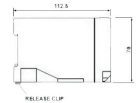
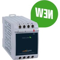
SIRAX CT610

- Summation current transformer sirax CT6xx line
- Camille Bauer
- Legal information....6
- Legal information
- 1.1 Safety and warning notices
- 1.2 Qualified personnel
- 1.3 Intended use
- 1.4 Disclaimer of liability
- 1.5 Feedback
- 1.6 Repair work and modifications
- 1.7 Calibration and new adjustment
- 1.8 Disposal
- Device may only be disposed in a professional manner
- 1.9 Return
- Damage by returning
- Introduction
- 2.1 Purpose of this document
- Scope
- Required knowledge
- 2.2 Scope of supply
- 2.3 Further documents
- Functional description
- Assembly and installation
- Electrical connections
Brand : Camille Bauer
Model : SIRAX CT610
Category : Multimeter