VT-3 - Uncategorized Sonel - Free user manual and instructions
Find the device manual for free VT-3 Sonel in PDF.


| Product Type | Non-contact AC Voltage Tester with Flashlight |
| Brand | Sonel |
| Model | VT-3 |
| Voltage Detection Ranges | High Mode: 100...1000 V AC; Low Mode: 12...1000 V AC |
| Frequency Range | 50/60 Hz |
| Measurement Category | CAT IV 1000 V (per EN 61010-2-030) |
| Protection Rating | IP67 (dust and water resistant) |
| Power Supply | 2 x AAA 1.5 V batteries |
| Dimensions | 160 x 23 x 25 mm (6.3 x 0.9 x 1.0 in) |
| Weight (with batteries) | 78 g (2.75 oz) |
| Weight (without batteries) | 55 g (1.94 oz) |
| Operating Temperature | 0°C to +50°C (32°F to 122°F) |
| Storage Temperature | -10°C to +60°C (14°F to 140°F) |
| Humidity | Max 80% |
| Operational Altitude | Up to 2000 m (6562 ft) |
| Indicators | Green (power), Orange (low range active), Red (voltage detected), audible beep |
| Auto-Off Time | Approx. 5 minutes of inactivity |
| Flashlight | White LED with lens, auto-off after approx. 5 minutes |
| Safety Compliance | EN 61326-1, EN 61326-2-2, EN 61010-031 |
| Warranty | Refer to manufacturer |
| Country of Origin | Poland (manufactured by Sonel S.A.) |
Frequently Asked Questions - VT-3 Sonel
User questions about VT-3 Sonel
0 question about this device. Answer the ones you know or ask your own.
Ask a new question about this device
Download the instructions for your Uncategorized in PDF format for free! Find your manual VT-3 - Sonel and take your electronic device back in hand. On this page are published all the documents necessary for the use of your device. VT-3 by Sonel.
USER MANUAL VT-3 Sonel
natural_image
Illustration of a handheld electronic device with two buttons labeled '12V' and a power button (no text or symbols beyond labels)


INSTRUKCJA OBSŁUGI 1
USER MANUAL 5
MANUAL DE USO 9
1 Flashlight
2 Battery cover
3 Flashlight button
4 Clip
5 Button of 12...1000 V measurement range
6 On/off button
7 LED indicators
8 Illuminating the measurement area
9 Detector tip

This symbol located near another symbol or terminal, indicates that the user should read the further information contained in the manual.

This symbol located near the terminal, indicates that in normal use there is a possibility of dangerous voltages.

Protection class II - double or reinforced insulation

This symbol indicates that the device must not be disposed of into any household waste containers, but must be provided to a designated collection point for electronic waste.

The device meets the legal requirements of the European Union.
CAT
Measurement category of the instrument.
Measurement categories according to EN IEC 61010-2-030:
- CAT II – concerns measurements performed in circuits directly connected to low voltage installations,
- CAT III – concerns measurements performed in buildings installations,
- CAT IV – concerns measurements performed at the source of low voltage installation.
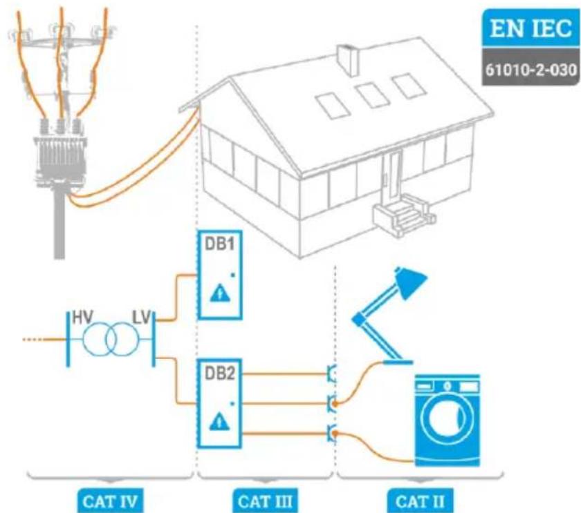
flowchart
graph TD
    A["Utility Pole"] --> B["House"]
    B --> C["DB1"]
    B --> D["DB2"]
    C --> E["Light Bulb"]
    D --> F["Light Bulb"]
    G["Power Supply"] --> H["HV"]
    G --> I["LV"]
    J["Electricity Generator"] --> K["CAT IV"]
    L["Electricity Generator"] --> M["CAT III"]
    N["Electricity Generator"] --> O["CAT II"]
    P["Smart Television"] --> Q["Water Heater"]
    R["Smart Lighting"] --> S["Switch"]
1.2 Safety
- The tester is used for voltage detecting. It must be used by skilled personnel only.
- Before using the tester, read the manual and follow its safety guidelines. Protection measures used in the tester may be ineffective, if not applied in accordance with manufacturer's instructions.
- Before using the tester, check if its operational by testing it on a known AC voltage (i.e. next applicable socket with live voltages).
- The type and thickness of the insulation, distance from the power source, shielded cables and other factors may affect the operation of the tester. If you are unsure about the test result, check the presence of voltage in a different way.
- Do not use the tester:
○ to test the absence of voltages, - if it is damaged or not working properly. If in doubt, replace it with another,
- for voltages higher than the upper measuring range indicated on the housing.
- Be careful when working with voltages above 30 V AC - there is a risk of electric shock.
- Comply with all applicable safety regulations. When working near live circuits (especially in places where an electric arc may be generated), use personal protective equipment.
- Do not operate the tester, when there is a warning of low battery level. Immediately replace the batteries with new ones.
- Inoperative flashlight may indicate damage to the device or discharged batteries.
- When the device is turned ON, the battery compartment must be closed.
- Looking directly into the LED lamp may damage your eyes.
- Dirt and moisture of the device may generate a risk of electrical shock.

NOTE!
- Unauthorized persons are not allowed to disassemble the device.
- Disassembling and repairs of the device must be done by skilled persons only.
2 Operation
2.1 Switching the tester ON
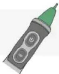
Press briefly You will hear a single beep and the green LED and module will light up. The tester is turned ON and ready to use.
2.2 Switching the tester OFF
Press briefly You will hear a double beep, and the green LED will go out.
2.3 Disabling and enabling sound signalling
a) When switching the tester ON
Press and hold button ⏻ until the green LED activates. Now, the tester works without sound signals. To restore the sound signalling, press and hold button ⏻ until the green LED starts flashing and the tester beeps.
b) When the tester is active
Press and hold button until the green LED starts to flash. To restore the sound signalling, press and hold button until the green LED starts flashing and the tester beeps.
2.4 Checking the tester
Before using the tester:
- check whether the green LED is ON,
- check the tester on a known AC voltage within the measuring range.
2.5 Voltage measurement in High Mode (100 ... 1000 V AC)
Approach the measuring tip of the tester to the tested AC voltage. If the device detects a voltage within the measuring range, the green LED goes out, the red LED is activated and a modulated beep is emitted.
2.6 Voltage measurement in Low Mode (12...1000 V AC)
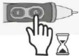
Press and hold the 12 V button. LED changes from green to orange to indicate the change of the measuring range. While pressing the 12 V button, approach the measuring tip of the tester to the tested AC voltage. If the voltage is detected, the orange LED goes out, the red LED starts flashing and a beep is emitted.
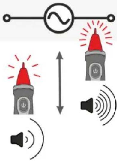
The frequency of light and sound signals increases, when the tester is closer to the tested voltage. If the high voltage is detected, the measurement mode automatically switches to 'High Mode': red LED lights continuously and a modulated beep is emitted.

- The tester does not show the voltage value.
- The cause of automatic mode change to 'High Mode' may be the type and thickness of the insulation, distance from the power source or other factors.
2.7 Indicator of discharged batteries
If the green LED is not active, replace the batteries. When the tester is turned ON and the battery level is too low for proper testing, the tester will beep three times and the green LED will go out, indicating that the tester cannot be used. Replace the batteries to continue testing.
2.8 Auto-Off
To prolong battery life, the tester will switch OFF automatically after approx. 5 minutes of inactivity. During the switching OFF process, the device will beep three times and the green LED will go out.
2.9 Flashlight
Briefly press button to turn ON/OFF the flashlight. To prolong battery life, the flashlight will switch OFF automatically after approx. 5 minutes The Auto-Off is signalled by double beep.

- If the battery level is too low for sufficient flashlight operation, the tester will indicate this fact by three beeps. Then the flashlight will go out.
- The module for voltage testing has own criterion for the batteries and in the above situation it may still running. In order to verify it, follow sec. 2.4.
3 Replacing batteries
- Carefully unscrew the battery cover a the back of the housing (element with flashlight LED).
- Remove old batteries and insert new ones, paying attention to their polarity.
- Carefully align the battery cover, ensure that the springs touch the contacts.
- Screw the cover onto tester until it feels tight, but do not use excessive force.
- Check the tester on a known AC voltage within the measuring range.
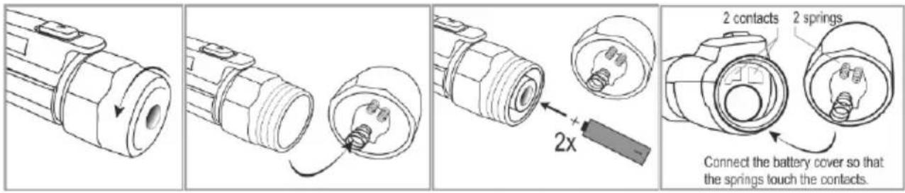

NOTE!
When replacing the batteries, make sure that you tightening the battery cover firmly to maintain protection level of IP67. When the cover is too loose or too tight, the waterproof and dustproof properties may be limited.

- When installing the batteries for the first time, remove the protective sticker from the contacts.
- Remove the batteries, if the product is not to be used for a long time.
4 Technical data
The device does not have the character of a standard and therefore is not subject to calibration. The proper form of control for this type of instrument is checking.
a) measurement category according to EN 61010-2-030 CAT IV 1000 V
b) Ingress Protections rating in accordance with EN 60529 IP67
c) contamination level....2
d) voltage detection ranges ....100...1000 V AC ....12...1000 V AC
e) frequency range 50 / 60 Hz
f) time to AUTO-OFF 5 min
g) indicators .....LED's (green, orange, red), beep
h) flashlight...... white LED with lens
i) power supply 2 x AAA 1.5 V battery
j) operating temperature 0°C...+50°C
k) storage temperature....-10°C...+60°C
I) humidity....max. 80%
m) operational altitude 2000 m
n) dimensions 160 x 23 x 25 mm
o) weight.... 78 g
p) weight without batteries 55 g
q) compliance with the requirements of ....EMC, LVD
r) compliance with the requirements of standards .....EN 61326-1, EN 61326-2-2, EN 61010-031
INDICADOR DE VOLTAJE CA SIN CONTACTO CON LINTERNA VT-3
natural_image
Illustration of a hand interacting with a pen and an hourglass (no text or symbols)3 s

natural_image
Illustration of a hand pressing a button next to a pen and an hourglass (no text or symbols)3 s


100...1000 V
100...1000 V

natural_image
Pure electrical circuit symbol for a resistor (no text or labels)




12...1000 V
natural_image
Illustration of a handheld electric toothbrush with green tip and two circular buttons (no text or symbols)
natural_image
Illustration of a hand holding a handheld electronic device with a button (no text or symbols)TRZYMAJ
HOLD
MANTENER APRETADO
GEDRÜCKT HALTEN
12...1000 V
SONEL S.A.
Wokulskiego 11
58-100 Świdnica
Poland
Customer Service
tel.+48 74 884 10 53
e-mail (GLOBAL):
customerservice@sonel.com
e-mail (PL):
bok@sonel.pl
- CAT
- Safety
- NOTE!
- Operation
- Switching the tester ON
- Switching the tester OFF
- Disabling and enabling sound signalling
- Checking the tester
- Voltage measurement in High Mode (100 ... 1000 V AC)
- Voltage measurement in Low Mode (12...1000 V AC)
- Indicator of discharged batteries
- Auto-Off
- Flashlight
- Replacing batteries
- Technical data
- INDICADOR DE VOLTAJE CA SIN CONTACTO CON LINTERNA VT-3
- SONEL S.A.
- Customer Service
Brand : Sonel
Model : VT-3
Category : Uncategorized