CMM-11 - Multimeter Sonel - Free user manual and instructions
Find the device manual for free CMM-11 Sonel in PDF.


| Product Type | Digital Multimeter |
| Brand | Sonel |
| Model | CMM-11 |
| Measurement Functions | AC/DC Voltage, AC/DC Current, Resistance, Capacitance, Frequency, Duty Cycle, Diode Test, Continuity |
| True RMS | Yes (AC V and AC A) |
| Display | LCD, 4-digit (max 9999), with backlight |
| Auto-Ranging | Yes (with manual override) |
| Bluetooth | Yes, v4.0+EDR for data transmission to Android devices |
| Flashlight | Built-in LED |
| Data Hold | Yes |
| Max/Min Recording | Yes |
| Auto-Off | After 15 minutes of inactivity |
| Safety Rating | CAT III 600V, double insulation (Class II) |
| Ingress Protection | IP65 |
| Power Supply | 2 x AAA 1.5V (alkaline) or 2 x AAA NiMH 1.2V rechargeable |
| Fuse Protection | 0.5A/600V fast (mA/μA range), 10A/600V fast (10A range) |
| Dimensions | 121 x 67 x 45 mm |
| Weight | 206 g (with batteries), 181 g (without) |
| Operating Temperature | +5°C to +40°C |
| Storage Temperature | -20°C to +60°C |
| Maximum Altitude | 2000 m |
| Standards Compliance | IEC 61010-1, EN 61010-031, EN 61326-1, etc. |
| Accessories Included | Test leads, user manual |
| Warranty | Manufacturer warranty (details in manual) |
Frequently Asked Questions - CMM-11 Sonel
User questions about CMM-11 Sonel
0 question about this device. Answer the ones you know or ask your own.
Ask a new question about this device
Download the instructions for your Multimeter in PDF format for free! Find your manual CMM-11 - Sonel and take your electronic device back in hand. On this page are published all the documents necessary for the use of your device. CMM-11 by Sonel.
USER MANUAL CMM-11 Sonel
natural_image
Line drawing of a vintage analog device with control panel and display (no text or symbols)
INSTRUKCJA OBSŁUGI 1
USER MANUAL 31
MANUAL DE USO 61
6.1 Przycisk MAX/MIN/R
CMM-11 multimeter is intended for measuring direct and alternating voltage, direct and alternating current, resistance, capacitance, frequency, duty cycle (filling) and for testing diodes and circuit continuity.
The most important features of CMM-11 include:
- Bluetooth wireless communication used for transmitting the measurement results to mobile devices with Android OS,
• automatic and manual range setting, - HOLD function used to maintain the read-pot on the meter screen,
- the backlight of the screen to read the measurement results in poor light,
• built-in flashlight for lighting the measurement location,
• sound signal for circuit continuity, - AUTO-OFF function,
• 4-digit display (read-out 9999).
CONTENTS
1 Introduction 35
2 Safety 36
2.1 General rules.... 36
2.2 Safety symbols.... 38
3 Preparing the meter for operation.... 38
4 Functional description 40
4.1 Measuring terminals and functions.... 40
4.2 Display 43
4.3 Leads 44
5 Measurements.... 45
5.1 Measurement of alternating voltage (AC)...... 45
5.2 Frequency measurement 46
5.3 Measurement % of duty cycle (pulse filling indicator) 46
5.4 DC voltage measurement.... 46
5.5 Measurement of resistance 47
5.6 Circuit continuity test 48
5.7 Diode test 48
5.8 Measurement of capacitance 49
5.9 Current measurement 49
5.9.1 The range of 10 A ....50
5.9.2 Range of mA, A....50
6 Special Features 51
6.1 MAX/MIN/R button 51
6.1.1 MAX/MIN function....51
6.1.2 Manual change of the range....51
6.2 Button 51
6.2.1 Flashlight 51
6.2.2 Wireless communication 51
6.3 Button HOLD 52
6.3.1 HOLD function 52
6.3.2 Display backlight 52
6.4 Auto-Off 52
7 Replacing the battery and fuses 53
8 Maintenance and care 55
9 Storage....56
10 Dismantling and Disposal....56
11 Technical data....57
11.1 Basic data 57
11.2 Operating data 59
11.3 Bluetooth specification 60
12 Manufacturer 60
1 Introduction
Thank you for purchasing Sonel multimeter. CMM-11 meter is a modern, easy and safe measuring device. Please acquaint yourself with this manual in order to avoid measuring errors and prevent possible problems in operation of the meter.
This manual contains three types of warnings. They are presented as a framed text describing the possible risks for the user and the device. Texts ⚠ WARNING describe situations, which may endanger user's life or health, when instructions are not followed. Texts ⚠ CAUTION! begin a description of a situation, which may result in device damage, when instructions are not followed. Indication of possible problems is preceded by symbol .
WARNING
- CMM-11 meter is designed to measure the current and AC/DC voltage, frequency, resistance, capacitance, as well as to test the circuit continuity and diodes. Any application that differs from those specified in the present manual may result in a damage to the device and constitute a source of danger for the user.
- CMM-11 meter must be operated only by appropriately qualified personnel with relevant certificates authorising the personnel to perform works on electric systems. Unauthorized use of the meter may result in its damage and may be a source of serious hazard to the user.
- Before operating the device, read thoroughly this manual and observe the safety regulations and guidelines provided by the producer. Failure to follow instructions specified in this manual may result in a damage to the device and be a source of serious hazard to the user.
2 Safety
2.1 General rules
In order to provide conditions for correct operation and the correctness of the obtained results, the following recommendations must be observed:
- before using the meter read carefully this manual,
- the meter should be operated only by qualified persons that have passed health and safety training,
- be very careful when measuring voltages exceeding (as per IEC 61010-1:2010/AMD1:2016):
60 V DC,
30 V AC RMS,
42.4 V AC of peak value,
as they generate a potential risk of electric shock,
- do not exceed the maximum limits of the input signal,
- during the voltage measurements do not switch the device in the current or resistance measuring mode and vice versa,
- when changing ranges, always disconnect the test leads from the tested circuit,
- measuring probes should be kept in the space provided, restricted by a special barrier to avoid accidental contact with exposed metal parts,
- If during the measurement symbol OL appears on the screen, it indicates that the measured value exceeds the measurement range,
- It is unacceptable to operate:
⇒ a damaged meter which is completely or partially out of order,
⇒ a device with damaged insulation of test leads,
⇒ a meter stored for an excessive period of time in disadvantageous conditions (e.g. excessive humidity).
- repairs may be carried out only by an authorised service point.
WARNING
- Never start the measurements if you have wet or damp hands.
- Do not perform measurements in explosive atmosphere (e.g. in the presence of flammable gases, vapours, dusts, etc.). Using the meter in such conditions may result in sparking and cause an explosion.
| The limit values of the input signal | |
| Function | The maximum input value |
| A AC, A DC | 10 A DC/AC RMS |
| μA/mA AC, μA/mA DC | 500 mA DC/AC RMS |
| V DC, V AC, frequency, duty cycle | 600 V DC/AC RMS |
| Resistance, capacitance, diode test | 250 V DC/AC RMS |
2.2 Safety symbols

This symbol located near another symbol or terminal, indicates that the user should read the further information contained in the manual.

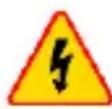
This symbol located near the terminal, indicates that in normal use there is a possibility of dangerous voltages.
Protection class II – double insulation
3 Preparing the meter for operation
After purchasing the meter, check whether the content of the package is complete.
Before performing the measurement:
- make sure that the battery level is sufficient for measurements,
- make sure that the device has fuse installed and efficient,
- check whether the meter casing and insulation of the test leads are not damaged,
- to ensure consistent measurement results it is recommended to connect black lead to COM terminal and red lead to other terminals,
- when the meter is not in use, set the function switch in OFF position.
The device has the AUTO-OFF function triggered after approx. 15 minutes of user inactivity. To turn the meter on again, set the function switch to OFF position and then set it at the desired function.
WARNING
- Connecting wrong or damaged leads may cause electric shock.
- The meter must not be connected to the voltage source when it is set to current or resistance measurement or to diode test. Failure to observe this precaution may damage the meter!
When using the meter, be sure to:
• discharge capacitors in the tested power sources,
- disconnect the power supply when measuring the resistance and diode tests.
- turn off the meter and disconnect test leads before removing the back cover to replace the battery or fuses.
WARNING
Do not use the meter if the cover of battery and/or fuse compartment is removed.

It is possible that in certain low ranges of AC or DC voltage, when the meter is not connected to the leads, the screen will show random and variable readings. This is a normal phenomenon, which results from the input sensitivity with high input resistance. When connected to a circuit, the read-out will stabilize and the meter will provide the correct value.
4 Functional description
4.1 Measuring terminals and functions
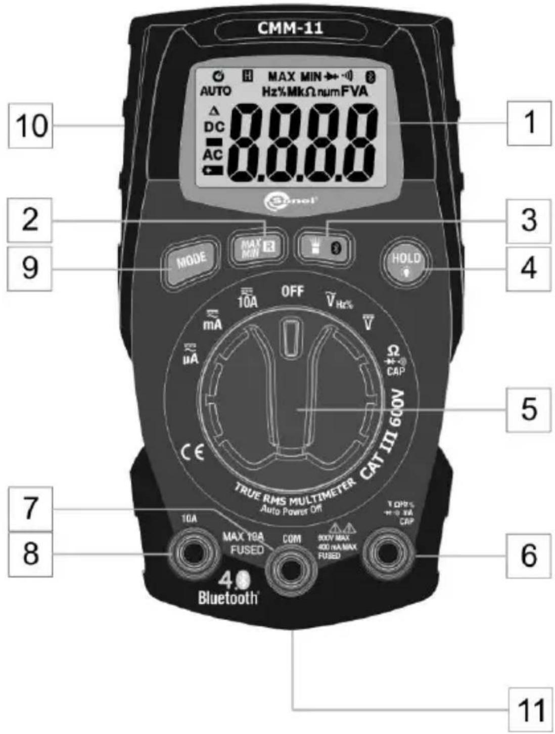
1 LCD display
2 MAX/MIN/R button
- Displaying the highest / lowest value from those currently recorded
⇒ To enable the function – press briefly
⇒ Selection of maximum or minimum value – press briefly
⇒ To disable the function – press and hold longer than 1 s.
- Manual change of the measuring range
⇒ To enable the function – press and hold longer than 1 s.
⇒ Range selection – press briefly
⇒ To disable the function – press and hold
3 Function button
- Flashlight mode (press briefly)
- Wireless communication mode (press and hold)
4 Button HOLD
- Freezing the measurement results on the display (press briefly)
- Activating the backlight of the display (press and hold)
5 Rotary switch
Function selection:
- A - measurement of direct and alternating current, up to 400.0 A
- ≡ mA – measurement of direct and alternating current, up to 400.0 mA
-
≡ 10A – measurement of direct and alternating current, up to 10 A
-
OFF – the meter is switched off
- _Hz2% - measurement of AC voltage, frequency, and duty cycle
- - DC voltage measurement
- Ω →●)) CAP – measurement of resistance, continuity, capacitance, diode test
6 Measuring terminal V Hz% mACAP
Measuring input for measurements other than current measurement up to 10 A.
7 COM measuring terminal
Measuring input, common for all measuring functions.
8 Measuring terminal 10A
Measuring input for AC and DC measurements, up to 10 A.
9 MODE button
Changing the measurement mode: DC / AC / Hz / % / V / resistance / continuity / diode test / capacity
10 Battery compartment cover (at the rear of the device)
11 Fuse compartment cover (at the rear of the device)
4.2 Display
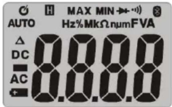
| H | HOLD function activated |
| - | Negative read-out value |
| AUTO | Automatic range setting |
| DC / AC | Constant signal / Alternating signal |
| Low battery | |
| V | Voltage measurement |
| Ω | Measurement of resistance |
| A | Current measurement |
| F | Measurement of capacitance |
| Hz | Measurement of frequency |
| n / μ / m / k / M | The prefix of multiple measurement unit |
| Continuity test | |
| Diode test | |
| Bluetooth wireless transmission | |
| Auto-off mode |
4.3 Leads
The manufacturer guarantees the correctness of read-outs only when original test leads are used.
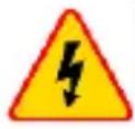
WARNING
Connecting wrong leads may cause electric shock or measurement errors.

- The probes are equipped with additional removable tip guards.
- The probes must be stored in a designated area.
5 Measurements
The content of this chapter should be thoroughly read and understood since it describes methods of measurements and basic principles of interpreting measurement results.
5.1 Measurement of alternating voltage (AC)
WARNING
- Electric shock hazard. The ends of measuring probes, due to their length, may not reach the live parts inside some network connections of low-voltage electrical equipment, because the contacts are arranged inside the sockets. In such a case, the read-out will be 0 V with the simultaneous presence of voltage in the socket.
- Before acknowledging the absence of voltage in the socket make sure that the ends of the probe touch the metal contacts inside the socket.

CAUTION!
Do not measure the voltage when an electric motor located within the circuit is being switched on or off. Resulting voltage spikes may damage the meter.
To perform AC voltage measurement:
- set the rotary switch at _Hz%
- briefly press MODE button, until symbol AC is shown on the display,
- connect black test lead to COM terminal, and red test lead to VΩHz% →●)) mACAP terminal,
- contact the tips of test probes to the points of measurement,
- read the measurement result on the display.
5.2 Frequency measurement
To perform frequency measurement:
- set the rotary switch at _Hz%
- press MODE button, until symbol Hz is shown on the display,
- connect black test lead to COM terminal, and red test lead to VΩHz% → mACAP terminal,
- contact the tips of test probes to the points of measurement,
- read the measurement result on the display.
5.3 Measurement % of duty cycle (pulse filling indicator)
To perform the measurement:
- set the rotary switch at _Hz%
- press MODE button, until symbol % is shown on the display,
- connect black test lead to COM terminal, and red test lead to VΩHz% → mACAP terminal,
- contact the tips of test probes to the points of measurement,
- read the measurement result on the display.
5.4 DC voltage measurement
WARNING
- Electric shock hazard. The ends of measuring probes, due to their length, may not reach the live parts inside some network connections of low-voltage electrical equipment, because the contacts are arranged inside the sockets. In such a case, the read-out will be 0 V with the simultaneous presence of voltage in the socket.
- Before acknowledging the absence of voltage in the socket make sure that the ends of the probe touch the metal contacts inside the socket.

CAUTION!
Do not measure the voltage when an electric motor located within the circuit is being switched on or off. Resulting voltage spikes may damage the meter.
To perform DC voltage measurement:
- set the rotary switch at
- connect black test lead to COM terminal, and red test lead to V Hz% mACAP terminal,
- contact the tips of test probes to the points of measurement; red probe should be applied to the point of higher potential,
- read the measurement result on the display.

5.5 Measurement of resistance
WARNING
Do not perform measurements on the circuit under the voltage. Before the measurement disconnect the power and discharge capacitors.
To perform the resistance measurement:
- set the rotary switch at CAP,
- connect black test lead to COM terminal, and red test lead to VΩHz% → mACAP terminal,
- press MODE button, to display on the screen,
- contact the tips of test probes to the points of measurement; the best solution is to disconnect one side of the tested element, to prevent the remaining part of the circuit interfere with the read-out of the resistance value,
- read the measurement result on the display.
5.6 Circuit continuity test
WARNING
Do not perform measurements on the circuit under the voltage. Before the measurement disconnect the power and discharge capacitors.
To perform the continuity test:
- set the rotary switch at CAP,
- connect black test lead to COM terminal, and red test lead to V Hz% mACAP terminal,
- press MODE button, to display • 🐎 on the screen,
- contact the tips of test probes to the points of measurement,
- read the measurement result on the display; the beep will be activated when resistance values are below approx. 50 Ω.
5.7 Diode test
WARNING
Do not perform measurements on the circuit under the voltage. Before the measurement disconnect the power and discharge capacitors. Do not test the diode under voltage.
To perform the diode test:
- set the rotary switch at ★● CAP,
- connect black test lead to COM terminal, and red test lead to VΩHz% → mACAP terminal,
- press MODE button, to display - and V on the screen,
- contact the tips of test probes to the diode. The red test probe should contact the anode and the black should contact cathode,
- read the test result on the display – the forward voltage is displayed.
⇒ For a typical silicon rectifier diode, it is approx. 0.7 V, and for a germanium diode it is approx. 0.3 V
⇒ For LEDs with a low power, typical voltage value is in the range of 1.2...5.0 V depending on the colour.
⇒ If the diode is polarized in the reverse direction, or there is a break in the circuit, the display will show OL.
When the diode is shorted, the meter will show a value near 0V ,
- after completing the measurements, remove test leads from the terminals of the meter.
5.8 Measurement of capacitance
WARNING
Risk of electric shock. Disconnect the power supply from the tested capacitor and discharge all capacitors before any starting capacity measurements.
To perform the measurement:
- set the rotary switch at CAP,
- connect black test lead to COM terminal, and red test lead to VΩHz% → mACAP terminal,
- press MODE button, to display nF on the screen,
- contact the probe tips to the tested capacitor,
- read the measurement result on the display.
5.9 Current measurement
WARNING
To avoid the electric shock, the device must not be connected to circuits in which the measuring voltage exceeds 1000 V.

CAUTION!
Do not make current measurements of 10 A for longer than 30 seconds. Exceeding this time may cause damage to the meter and/or test leads. When the current of 10 A, the interval between successive tests should be approx. 15 minutes.
5.9.1 The range of 10 A
To perform the current measurement:
- set the rotary switch at 10A,
-
press MODE button to display the following values on the display:
⇒ AC, if you measuring Alternating Current,
⇒ DC, if you measuring Direct Current, -
connect black test lead to COM terminal and red test lead to 10A terminal,
- disconnect the power supply from the tested circuit and then connect the meter in series (for DC circuits: connect the red probe to the positive pole),
- turn on the power supply of the circuit,
- read the measurement result on the display.
5.9.2 Range of mA, μA
To perform the current measurement:
- set the rotary switch at or AmA (it is recommended to start the measurement from the position of the rotary switch in the higher range)
- press MODE button to display the following values on the display: AC, if you measuring Alternating Current, DC, if you measuring Direct Current,
- connect black test lead to COM terminal, and red test lead to VΩHz% → mACAP terminal,
- disconnect the power supply from the tested circuit and then connect the meter in series (for DC circuits: connect the red probe to the positive pole),
- turn on the power supply of the circuit,
- read the measurement result on the display.
6 Special Features
6.1 MAX/MIN/R button
6.1.1 MAX/MIN function
- To enable the mode, press MAX/MIN/R.
- Press MAX/MIN/R button to switch between the extreme values of the on-going measurement.
MAX control light - the meter displays the highest value out of existing measurement readings.
MIN control light - the meter displays the lowest value out of existing measurement readings.
- To disable the function, press and hold MAX/MIN/R button for approx. 1 second.
6.1.2 Manual change of the range
- To enable the function, press and hold MAX/MIN/R button longer than 1 second.
- Press MAX/MIN/R, to switch the measuring range.
- To disable the function, press and hold MAX/MIN/R button.
6.2 Button

6.2.1 Flashlight
Briefly press button, to turn on or off the flashlight mode.
6.2.2 Wireless communication
The multimeter is equipped with a wireless data transfer mode for devices with installed Sonel Multimeter Mobile software. To enable the mode, long press button. The meter will be visible in the Bluetooth manager of any receiver device as CMM-11.
Details of cooperation with the mobile application are provided in Sonel Multimeter Mobile manual.
6.3 Button HOLD

6.3.1 HOLD function
This function is used to 'freeze' the measurement result on the display. To do this, briefly press HOLD button. When the function is enabled, the display shows symbol H.
To return to the normal operation mode of the device, press HOLD button again.
6.3.2 Display backlight
Pressing and holding HOLD button for 2 seconds will turn ON/OFF the display backlight function.
6.4 Auto-Off
The meter automatically shuts off after 15 minutes of user inactivity. Symbol in the upper left corner of the display indicates activated function.
Auto-off function may be temporarily disabled. For this purpose:
- set the rotary switch at OFF position,
- press and hold MODE button,
- set the rotary switch at the desired measuring function,
- wait until the meter reaches the measurement readiness,
- release MODE button.

Each pass of the rotary switch through "OFF" position with non-pressed MODE button, will activate again the Auto-Off function.
7 Replacing the battery and fuses
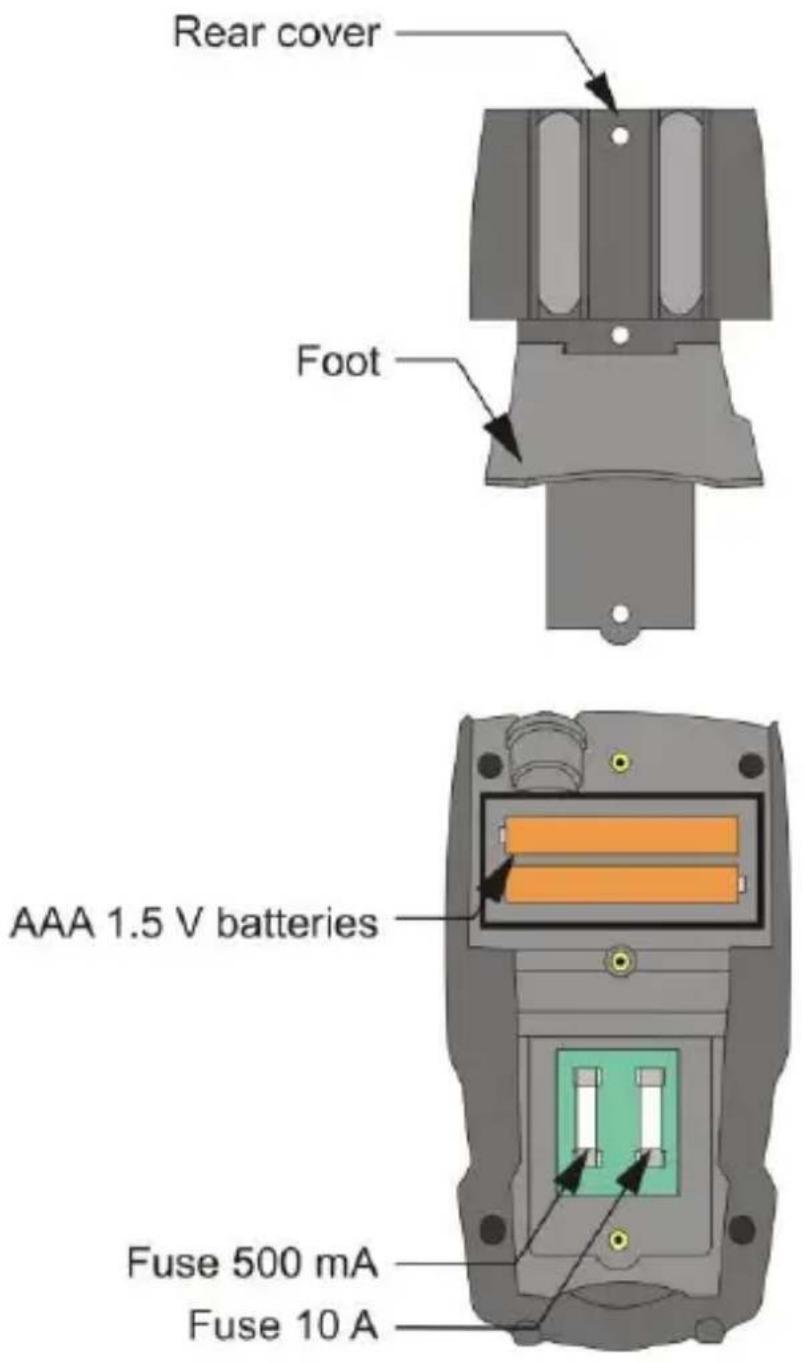
CMM-11 is powered by two LR03 AAA 1.5 V batteries or two NiMH LR03 AAA 1.2 V rechargeable batteries. It is recommended to use alkaline batteries.
The device is protected by the following fuses:
• 500 mA/500 V fast-acting for the range of A/mA,
- 10 A/600 V fast-acting for the range of 10 A.
WARNING
- If the test leads are left in the meter's terminals during replacement of the fuses, they may generate a risk of electric shock.
- To avoid electric shock, do not use the meter if the battery compartment cover is not in place or is not properly fastened.
To replace batteries or fuses:
- remove test leads from the terminals of the meter.
- set the rotational function selector at OFF,
- lift the foot at the back of the meter,
- loosen the three screws fixing the cover,
- remove the cover and:
⇒ remove the (rechargeable) batteries and insert new, observing the polarity:
⇒ replace the required fuse,
- put on the cover and tighten the fixing screws.

CAUTION!
Always use only fuses with parameters specified in this manual.

- While performing the measurements with the battery symbol displayed, the user must be aware of additional measurement uncertainties or unstable operation of the device.
- If the meter does not work properly, check the fuses and batteries in order to ensure that they are in proper condition and properly installed in the device.
8 Maintenance and care
The digital multimeter has been designed for many years of reliable use, provided that the following recommendations are observed for its maintenance and care:
- THE METER MUST BE DRY. Wipe the dampened mater.
- THE METER MUST BE USED AND STORED IN NORMAL TEMPERATURES. Extreme temperatures may shorten the life of electronic components and distort or melt plastic parts.
- THE METER MUST BE HANDLED CAREFULLY AND GENTLY. Dropping the meter may damage its electronic elements or the housing.
- THE METER MUST BE KEPT CLEAN. From time to time wipe the housing with a damp cloth. DO NOT use chemicals, solvents or detergents.
- USE ONLY NEW BATTERIES OF RECOMMENDED SIZE AND TYPE. Remove the old or discharged batteries from the meter to avoid leakage and damage.
- IF THE METER IS TO BE STORED FOR LONGER THAN 60 DAYS, remove the batteries and keep them separately.

The electronic system of the meter does not require maintenance.
9 Storage
During the storage of the device, the following recommendations must be observed:
- disconnect the test leads from the meter,
- make sure that the meter and accessories are dry,
- when the device is to be stored for longer time, remove the battery.
10 Dismantling and Disposal
Worn-out electric and electronic equipment should be gathered selectively, i.e. it must not be placed with waste of another kind.
Worn-out electronic equipment should be sent to a collection point in accordance with the law of waste electrical and electronic equipment.
Before the equipment is sent to a collection point, do not dismantle any elements.
Observe local regulations concerning disposal of packages, waste batteries and accumulators.
11 Technical data
11.1 Basic data
⇒ "m.v." means a standard measured value.
True RMS measurement for AC current
| Range | Resolution | Accuracy |
| 400.0 μA | 0.1 μA | ± (2.0% m.v. + 5 digits) |
| 4000 μA | 1 μA | ± (2.5% m.v. + 5 digits) |
| 40.00 mA | 0.01 mA | |
| 400.0 mA | 0.1 mA | |
| 10.00 A | 0.01 A | ± (3.0% m.v. + 7 digits) |
- Frequency range:
50 Hz...60 Hz (other cycles)
DC current measurement
| Range | Resolution | Accuracy |
| 400.0 μA | 0.1 μA | ± (1.0% m.v. + 3 digits) |
| 4000 μA | 1 μA | ± (1.5% m.v. + 3 digits) |
| 40.00 mA | 0.01 mA | |
| 400.0 mA | 0.1 mA | |
| 10.00 A | 0.01 A | ± (2.5% m.v. + 5 digits) |
True RMS voltage measurement
| Range | Resolution | Accuracy |
| 4.000 V | 0.001 V | ± (1.0% m.v. + 5 digits) |
| 40.00 V | 0.01 V | |
| 400.0 V | 0.1 V | |
| 600 V | 1 V | ± (1.2% m.v. + 5 digits) |
- Input Impedance: >14 MΩ
- Frequency range:
50 Hz...60 Hz (other cycles)
DC voltage measurement
| Range | Resolution | Accuracy |
| 400.0 mV | 0.1 mV | ± (1.0% m.v. + 8 digits) |
| 4.000 V | 0.001 V | ± (1.0% m.v. + 3 digits) |
| 40.00 V | 0.01 V | |
| 400.0 V | 0.1 V | |
| 600 V | 1 V | ± (1.2% m.v. + 3 digits) |
• Input impedance: ≥6 MΩ
Measurement of resistance
| Range | Resolution | Accuracy |
| 400,0 Ω | 0.1 Ω | ± (1.0 % m.v. + 4 digits) |
| 4.000 kΩ | 0.001 kΩ | ± (1.5 % m.v. + 5 digits) |
| 40.00 kΩ | 0.01 kΩ | |
| 400.0 kΩ | 0.1 kΩ | |
| 4.000 MΩ | 0.001 MΩ | |
| 40.00 MΩ | 0.01 MΩ |
Measurement of capacitance
| Range | Resolution | Accuracy |
| 40.00 nF | 0.01 nF | ± (5.0 % m.v. + 35 digits) |
| 400.0 nF | 0.1 nF | ± (3.0 % m.v. + 5 digits) |
| 4.000 μF | 0.001 μF | |
| 40.00 μF | 0.01 μF | |
| 400.0 μF | 0.1 μF | ± (4.0 % m.v. + 5 digits) |
| 4000 μF | 1 μF | ± (5.0 % m.v. + 5 digits) |
Measurement of frequency
| Range | Resolution | Accuracy |
| 9.999 Hz | 0.001 Hz | ± (1.0 % m.v. + 5 digits) |
| 99.99 Hz | 0.01 Hz | |
| 999.9 Hz | 0.1 Hz | |
| 9.999 kHz | 0.001 kHz | |
| 99.99 kHz | 0.01 kHz |
Duty cycle measurement
| Range | Resolution | Accuracy |
| 0.1... 99.9% | 0.1% | ± (1.2 % m.v. + 2 digits) |
- Sensitivity: the minimum value of the effective voltage of 8 V
- Pulse width: 100 s - 100 ~ms
• Frequency: 5 Hz to 99.99 kHz
11.2 Operating data
a) measurement category according to IEC 61010-1....CAT III 600 V
b) type of insulation ....double, Class II
c) degree of housing protection acc. to PN-EN 60529 IP65
d) pollution degree 2
e) power supply of the meter....2 x AAA 1.5 V battery ....2 x AAA NiMH 1.2 V rechargeable battery
f) diode test I = 0.3 mA, U₀ < 3.3 V DC
g) continuity test ....I < 0.5 mA, acoustic signal for R < 50 Ω
h) indication for range exceeding ....OL symbol
i) low battery indication .... symbol +
j) measurement rate 2 measurements per second
k) input impedance
- V AC ....>14 MΩ
- V DC ....≥6 MΩ
I) AC read-out ....True RMS (A AC and V AC)
m) display......LCD, 4 digit with backlit
......9999 counts with function indicators
n) dimensions....121 x 67 x 45 mm
o) meter weight 206 g
p) meter weight (without batteries)....181 g
q) fuses....mA and μA range: 0.5 A / 600 V fast, ....A range: 10 A / 600 V fast
r) operating temperature ....+5..+40°C
s) operating humidity ....../decreasing linearly to 50% at temp. 40°C
t) storage temperature ....-20..+60°C
u) storage humidity ....../< 80%
v) maximum operating altitude 2000 m
w) Auto-Off function ....approx. 15 min
x) compliance with the requirements of the following standards....EN 61010-1....EN 61010-031, EN 61010-2-033, EN 61326-1, EN 61326-2-2
y) quality standard ....ISO 9001

SONEL S.A. hereby declares that the radio device type CMM-11 complies with Directive 2014/53/EU. The full text of the EU Declaration of Conformity is available at the following website address: https://sonel.pl/en/download/declaration-of-conformity/
11.3 Bluetooth specification
Version v4.0+EDR
Frequency range 2400 MHz...2483,5 MHz (ISM band)
Guard band....2 MHz < f < 3,5 MHz
Modulation method...... GFSK, 1 Mbps, 0,5 gauss
Receiving signal range....-82...-20 dBm
Transmission power minimum ....-18...+4 dBm
12 Manufacturer
The provider of guarantee and post-guarantee services is:
SONEL S.A.
Wokulskiego 11
58-100 Świdnica
Poland
tel. +48 74 884 10 53 (Customer Service)
e-mail: customerservice@sonel.com
web page: www.sonel.com

CAUTION!
Service repairs must be performed only by the manufacturer.

MANUAL DE USO
MULTÍMETRO DIGITAL
CMM-11
CE
- Przycisk MAX/MIN/R
- CONTENTS
- Introduction
- WARNING
- Safety
- General rules
- Safety symbols
- Preparing the meter for operation
- Functional description
- LCD display
- MAX/MIN/R button
- Function button
- Button HOLD
- Rotary switch
- Display
- Leads
- Measurements
- Measurement of alternating voltage (AC)
- CAUTION!
- Frequency measurement
- Measurement % of duty cycle (pulse filling indicator)
- DC voltage measurement
- Measurement of resistance
- Circuit continuity test
- Diode test
- Measurement of capacitance
- Current measurement
- The range of 10 A
- Range of mA, μA
- Special Features
- MAX/MIN/R button
- MAX/MIN function
- Manual change of the range
- Button
- Flashlight
- Wireless communication
- Button HOLD
- HOLD function
- Display backlight
- Auto-Off
- Replacing the battery and fuses
- Maintenance and care
- Storage
- Dismantling and Disposal
- Technical data
- Basic data
- Operating data
- Bluetooth specification
- Manufacturer
- SONEL S.A.
- MANUAL DE USO
- MULTÍMETRO DIGITAL
Brand : Sonel
Model : CMM-11
Category : Multimeter