CMM-10 - Multimeter Sonel - Free user manual and instructions
Find the device manual for free CMM-10 Sonel in PDF.


| Product Type | Multimeter |
| Brand | Sonel |
| Model | CMM-10 |
| Dimensions | 138 x 68 x 37 mm |
| Weight | Approx. 210 g |
| Power Supply | 9 V battery (alkaline recommended) |
| Display | 5000 counts LCD with function indicators |
| Measurement Functions | AC/DC voltage, AC/DC current, resistance, capacitance, frequency, duty cycle, temperature, diode test, continuity |
| DC Voltage Ranges | 400 mV to 600 V, accuracy ±(0.5% + 2 digits) to ±(1.5% + 2 digits) |
| AC Voltage Ranges | 400 mV to 600 V, accuracy ±(1.2% + 3 digits) to ±(2.0% + 4 digits) |
| DC Current Ranges | 400 μA to 10 A, accuracy ±(1.0% + 3 digits) to ±(2.5% + 5 digits) |
| AC Current Ranges | 400 μA to 10 A, accuracy ±(1.5% + 5 digits) to ±(3.0% + 7 digits) |
| Resistance Ranges | 400 Ω to 40 MΩ, accuracy ±(1.0% + 2 digits) to ±(2.0% + 3 digits) |
| Capacitance Ranges | 40 nF to 100 μF, accuracy ±(3.0% + 5 digits) to ±(5.0% + 7 digits) |
| Frequency Ranges | 5 Hz to 10 MHz, accuracy ±(1.2% + 3 digits) to ±(1.5% + 5 digits) |
| Temperature Range | -20°C to +760°C (-4°F to +1400°F), accuracy ±(3% + 5°C/9°F) |
| Special Features | Autoranging/manual ranging, Data Hold, Relative mode, backlight, Auto Power Off (30 min) |
| Safety Rating | CAT II 600 V, double insulation, IP40, pollution degree 2 |
| Fuses | 0.5 A/250 V fast blow (mA/μA range), 10 A/250 V fast blow (A range) |
| Cleaning and Maintenance | Keep dry, clean with damp cloth, avoid solvents, store at normal temperatures |
| Spare Parts | Battery, fuses, original test leads (recommended) |
| Repairability | Service only by manufacturer (Sonel S.A., Poland) |
Frequently Asked Questions - CMM-10 Sonel
User questions about CMM-10 Sonel
0 question about this device. Answer the ones you know or ask your own.
Ask a new question about this device
Download the instructions for your Multimeter in PDF format for free! Find your manual CMM-10 - Sonel and take your electronic device back in hand. On this page are published all the documents necessary for the use of your device. CMM-10 by Sonel.
USER MANUAL CMM-10 Sonel

INSTRUKCJA OBSŁUGI 1
USER MANUAL 28
MANUAL DE USO 55
Multimeter CMM-10 has been designed for the purpose of measurements of AC/DC voltage, AC/DC current, resistance, capacitance, frequency, duty cycle, temperature and also for testing diodes and continuity.
The most important features of CMM-10 are:
• automatic or manual regulation of the measurement range,
- DATA HOLD function, which facilitates readings of measurements in the case of insufficient lighting or in inaccessible places,
- REL function, which allows you to make measurements relative to a stored reference value,
• circuit continuity sound signalling,
- the function of automatic switching of the meter into the standby mode in order to prolong the durability of batteries,
- 3 78 digits display (5000 counts).
CONTENTS
1 Introduction.... 32
2 Safety 33
3 Preparation of the meter for operation 35
4 Functional description 36
4.1 Measurement sockets and elements of selection of the measurement function....36
4.1.1 Sockets....37
4.1.2 Elements of selection of the measurement function....37
4.2 LCD display....38
4.3 Test leads 38
5 International Safety Symbols.... 39
6 Measurements.... 39
6.1 DC voltage measurements 39
6.2 AC voltage measurements 40
6.3 DC current measurements....40
6.4 AC current measurements....42
6.5 Resistance measurements 43
6.6 Continuity Measurements....43
6.7 Diode Measurements 44
6.8 Capacitance measurements....44
6.9 Frequency or % duty cycle measurements 45
6.10 Temperature measurements 45
7 Special functions 46
7.1 Autoranging/manual range selection....46
7.2 Relative mode....46
7.3 DATA HOLD function 47
7.4 Display backlight 47
8 Battery replacement 47
9 The fuses replacement.... 48
10 Cleaning and maintenance 49
11 Storage 50
12 Dismantling and utilization 50
13 Technical data.... 50
13.1 Basic data 50
13.2 Operating data 53
14 Service.... 54
1 Introduction
The CMM-10 meter is a modern, high-quality measuring device, which is easy and safe to use. Please acquaint yourself with the present manual in order to avoid measuring errors and prevent possible problems related to operation of the meter.
In the present manual we apply three kinds of warnings. These are texts in frames, which describe possible dangers both for the user and the meter itself. The messages starting from the word 'WARNING:' describe situations which imply a risk for life or health should the recommendations presented in the present manual not be observed. The word 'CAUTION!' introduces a description of a situation where non-observance of the recommendations presented in the present manual may imply damage for the meter. Indications of possible problems are preceded by the word 'Note:',
WARNING:
The purpose of the CMM-10 meter is to realise measurements of AC/DC voltage, AC/DC current, resistance, capacitance, frequency, duty cycle, diode test, continuity and temperature. Using the meter in a manner which does not comply with the recommendations specified in the present manual may lead to its damage and constitutes a source of a serious risk for the user.
WARNING:
The CMM-10 meter may be operated solely by qualified and properly authorised personnel for work at electric installations. Using the meter by unauthorised personnel may lead to its damage and constitutes a source of a serious risk for the user.
WARNING:
Before using the instrument acquaint yourself with the present manual and observe the safety regulations and recommendations specified by the manufacturer.
2 Safety
In order to guarantee proper operation and correctness of the obtained results it is necessary to observe the following recommendations:
- Before commencing operation of the meter please acquaint yourself thoroughly with the present manual,
- The instrument should be operated solely by properly qualified personnel, who also must be trained regarding the industrial safety regulations,
- Use great care when making measurements if the voltages are greater than 30 V AC rms or 60 V DC. These voltages are considered a shock hazard,
- Do not exceed the maximum allowable input range of any function,
- Never ground yourself when taking electrical measurements. Do not touch exposed metal pipes, outlets, fixtures, etc., which might be at ground potential. Keep your body isolated from ground by using dry clothing, rubber shoes, rubber mats, or any approved insulating material,
- Turn off power to the circuit under test before cutting, unsoldering, or breaking the circuit. Small amounts of current can be dangerous,
- When using the probes, keep your fingers behind the finger guards on the probes,
- If “OL” appears in the display during a measurement, the value exceeds the range you have selected. Change to a higher range,
- It is prohibited to operated the meter:
⇒ If it is damaged and completely or partially out of order,
⇒ If the insulation of the test leads has been damaged,
⇒ If it has been stored for an excessive period of time in inadequate conditions (e.g. if it is humid),
- Repairs must be realised solely by an authorised service workshop.
WARNING: Do not realise measurements in environments in which there are inflammable gases. Otherwise operation of the meter under such conditions may cause sparking and explosion.
| CAUTION! | |
| Input Limits | |
| Function | Maximum Input |
| V DC or V AC | 600 V DC/AC rms |
| mA AC/DC | 500 mA 250 V fast acting fuse |
| A AC/DC | 10 A 250 V fast acting fuse |
| Frequency, resistance, capacitance, duty cycle, diode test, continuity | 250 V DC/AC rms |
| Temperature | 250 V DC/AC rms |
3 Preparation of the meter for operation
Having purchased the meter examine completeness of the contents of the package.
Before measurements commence, it is necessary to realise the following actions:
- Make sure the conditions of the batteries or accumulators permit to realise measurements,
- Make sure the casing of the meter and the insulation of the test leads are not damaged,
- Insert the black test lead into the negative COM terminal and the red test lead into the other positive terminal,
- ALWAYS turn the function switch to the OFF position when the meter is not in use. This meter has Auto OFF that automatically shuts the meter OFF if 30 minutes elapse between uses.
WARNING:
Connection of inappropriate or damaged test leads constitutes a risk of an electric shock with a dangerous voltage.
Note:
On some low AC and DC voltage ranges, with the test leads not connected to a device, the display may show a random, changing reading. This is normal and is caused by the high-input sensitivity. The reading will stabilize and give a proper measurement when connected to a circuit.
4 Functional description
4.1 Measurement sockets and elements of selection of the measurement function
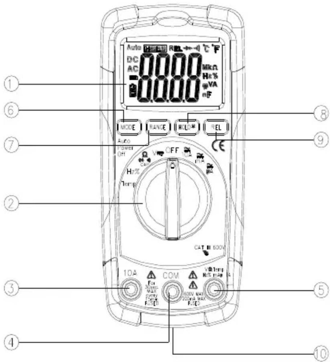
CMM-10
4.1.1 Sockets
3 measurement socket 10 A
Measurement socket for the purpose of measurements of direct current up to 10 A.
4 measurement socket COM
Measurement socket common for all the measurement functions.
5 measurement socket VΩTEMPHz%mAμA
Measurement socket for all the measurement functions except of 10 A current measurements.
4.1.2 Elements of selection of the measurement function
1 5000 count Liquid Crystal Display with symbolic signs
2 Rotational selector
Selection of function:
- Temp – Celsius or Fahrenheit temperature measurement
• Hz% – frequency and duty cycle measurement
- Ω CAP – resistance, capacitance and continuity measurement and diode testing
- V = -AC and DC voltage measurement
- OFF – meter off
- 10A ≈ - AC and DC current measurement up to 10 A
- mA ≡ - AC and DC current measurement up to 400 mA
- A ≡ - AC and DC current measurement up to 400 A
6 MODE button
- Measurement mode selection: Ohm / Diode / Continuity / Cap, DC / AC, Hz / %Duty
7 RANGE button
- Manual range selection
8 HOLD button
- Data Hold function
- Back Light function
9 REL button
- Relative measurement function
10 battery compartment lid
4.2 LCD display
- continuity
- battery status
+ - diode
Ω - resistance in ohms
Hz – hertz (frequency)
DC, AC – voltage (current) direct, alternating
°C – Celsius degrees
°F – Fahrenheit degrees
AUTO – auto range
REL – relative
HOLD – display hold
4.3 Test leads
The manufacturer guarantees correct measurement indications provided original test leads are used.
WARNING:
Connection of inadequate test leads constitutes a risk of electric shock with a dangerous voltage or may be a cause of measurement errors.
5 International Safety Symbols

This symbol, adjacent to another symbol or terminal, indicates the user must refer to the manual for further information.
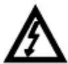
This symbol, adjacent to a terminal, indicates that, under normal use, hazardous voltages may be present

Double insulation
6 Measurements
It is recommended to get acquainted thoroughly with the contents of the present chapter since it describes the measurement systems, the manner of realisation of measurements and the basic principles of interpretation of the results.
6.1 DC voltage measurements
CAUTION!
Do not measure DC voltages if a motor on the circuit is being switched ON or OFF. Large voltage surges may occur that can damage the meter.
In order to realise a measurement of DC voltage, it is necessary to realise the following actions:
- Set the function switch to the V position,
- With the RANGE button set the measurement range manually if necessary,
- Insert the black test lead banana plug into the negative COM jack. Insert the red test lead banana plug into the positive VΩTEMPHz%mAμA jack,
- Touch the black test probe tip to the negative side of the circuit. Touch the red test probe tip to the positive side of the circuit,
- Read the voltage in the display.
6.2 AC voltage measurements
CAUTION!
Do not measure AC voltages if a motor on the circuit is being switched ON or OFF. Large voltage surges may occur that can damage the meter.
WARNING:
Risk of Electrocution. The probe tips may not be long enough to contact the live parts inside some 240 V outlets for appliances because the contacts are recessed deep in the outlets. As a result, the reading may show 0 volts when the outlet actually has voltage on it. Make sure the probe tips are touching the metal contacts inside the outlet before assuming that no voltage is present.
In order to realise a measurement of AC voltage, it is necessary to realise the following actions:
- Set the function switch to the V position,
- With the RANGE button set the measurement range manually if necessary,
- Insert the black test lead banana plug into the negative COM jack. Insert the red test lead banana plug into the positive VΩTEMPHz%mAμA jack,
- Touch the black test probe tip to the neutral side of the circuit.
Touch the red test probe tip to the "hot" side of the circuit, - Read the voltage in the display.
6.3 DC current measurements
WARNING:
To avoid electric shock, do not measure DC current on any circuit whose voltage exceeds 250 V.
CAUTION!
Do not make 10 A current measurements for longer than 30 seconds. Exceeding 30 seconds may cause damage to the meter and/or the test leads.
In order to realise a measurement of DC current, it is necessary to realise the following actions:
- Insert the black test lead banana plug into the negative COM jack,
- For current measurements up to 4000 μA DC, set the function switch to the μA position and insert the red test lead banana plug into the VΩTEMPHz%mAμA jack,
- For current measurements up to 400 mA DC, set the function switch to the mA position and insert the red test lead banana plug into the VΩTEMPHz%mAμA jack,
- For current measurements up to 10A DC, set the function switch to the 10A position and insert the red test lead banana plug into the 10A jack,
- Press the MODE button to indicate "DC" on the display,
- Remove power from the circuit under test, then open up the circuit at the point where you wish to measure current,
- Touch the black test probe tip to the negative side of the circuit. Touch the red test probe tip to the positive side of the circuit,
- Apply power to the circuit,
- Read the current in the display.
6.4 AC current measurements
WARNING:
To avoid electric shock, do not measure AC current on any circuit whose voltage exceeds 250 V.
CAUTION!
Do not make current measurements on the 10 A scale for longer than 30 seconds. Exceeding 30 seconds may cause damage to the meter and/or the test leads.
In order to realise a measurement of AC current, it is necessary to realise the following actions:
- Insert the black test lead banana plug into the negative COM jack,
- For current measurements up to 4000 μA AC, set the function switch to the μA position and insert the red test lead banana plug into the VΩTEMPHz%mAμA jack,
- For current measurements up to 400 mA AC, set the function switch to the mA position and insert the red test lead banana plug into the VΩTEMPHz%mAμA jack,
- For current measurements up to 10 A AC, set the function switch to the 10A position and insert the red test lead banana plug into the 10A jack,
- Press the MODE button to indicate "AC" on the display,
- Remove power from the circuit under test, then open up the circuit at the point where you wish to measure current,
- Touch the black test probe tip to the neutral side of the circuit. Touch the red test probe tip to the "hot" side of the circuit,
- Apply power to the circuit,
- Read the current in the display.
6.5 Resistance measurements
WARNING:
To avoid electric shock, disconnect power to the unit under test and discharge all capacitors before taking any resistance measurements. Remove the batteries and unplug the line cords.
In order to realise a measurement of the resistance it is necessary to realise the following actions:
- Set the function switch to the CAP position,
- Insert the black test lead banana plug into the negative COM jack. Insert the red test lead banana plug into the positive VΩTEMPHz%mAμA jack,
- Press the MODE button to indicate “^” on the display,
- With the RANGE button set the measurement range manually if necessary,
- Touch the test probe tips across the circuit or part under test. It is best to disconnect one side of the part under test so the rest of the circuit will not interfere with the resistance reading,
- Read the resistance in the display.
6.6 Continuity Measurements
WARNING:
To avoid electric shock, never measure continuity on circuits or wires that have voltage on them.
In order to realise continuity test it is necessary to realise the following actions:
- Set the function switch to the CAP position,
- Insert the black test lead banana plug into the negative COM jack. Insert the red test lead banana plug into the positive VΩTEMPHz%mAμA jack,
- Press the MODE button to indicate • and “^” on the display,
- Touch the test probe tips to the circuit or wire you wish to check,
- If the resistance is less than approximately 150 , the audible signal will sound. If the circuit is open, the display will indicate "OL",
6.7 Diode Measurements
WARNING:
To avoid electric shock, do not test any diode that has voltage on it.
In order to realise diode test it is necessary to realise the following actions:
- Set the function switch to the CAP position,
- Insert the black test lead banana plug into the negative COM jack. Insert the red test lead banana plug into the positive VΩTEMPHz%mAμA jack,
- Press the MODE button to indicate and "V" on the display,
- Touch the test probes to the diode under test. Forward voltage will typically indicate 0.3 V to 0.7 V. Reverse voltage will indicate “OL”. Shorted devices will indicate near 0 V and an open device will indicate “OL” in both polarities.
Note:
The value indicated in the display during the diode check is the forward voltage.
6.8 Capacitance measurements
WARNING:
To avoid electric shock, disconnect power to the unit under test and discharge all capacitors before taking any capacitance.
In order to realise capacitance measurement it is necessary to realise the following actions:
- Set the rotary function switch to the → CAP position,
- Insert the black test lead banana plug into the negative COM jack. Insert the red test lead banana plug into the positive VΩTEMPHz%mAμA jack,
- Press the MODE button to indicate "nF",
- Touch the test leads to the capacitor to be tested,
- Read the capacitance value in the display.
6.9 Frequency or % duty cycle measurements
In order to realise frequency or \% duty cycle measurement it is necessary to realise the following actions:
- Set the rotary function switch to the Hz/% position,
-
Insert the black test lead banana plug into the negative COM jack. Insert the red test lead banana plug into the positive VΩTEMPHz%mAμA jack,
-
Touch the test probe tips to the circuit under test,
- Read the frequency on the display,
- Press the MODE button to indicate “%”,
- Read the % duty cycle in the display.
6.10 Temperature measurements
In order to realise temperature measurement it is necessary to realise the following actions:
- Set the function switch to the Temp position,
- Insert the temperature probe into the input jacks COM and VΩTEMPHz%mAμA, making sure to observe the correct polarity,
- Touch the Temperature Probe head to the part whose temperature you wish to measure. Keep the probe touching the part under test until the reading stabilizes (about 30 seconds),
- Read the temperature in the display,
- When setting "Celsius" or "Fahrenheit" into initial state, please remove the battery cover and slip the "°C /°F" switch to the corresponding position.
7 Special functions
7.1 Autoranging/manual range selection
When the meter is first turned on, it automatically goes into autoranging. This automatically selects the best range for the measurements being made and is generally the best mode for most measurements. For measurement situations requiring that a range be manually selected, perform the following:
- Press the RANGE key. The “AUTO” display indicator will turn off,
- Press the RANGE key to step through the available ranges until you select the range you want,
- Press and hold the RANGE button for 2 seconds to exit the ManualRanging mode and return to AutoRanging.
7.2 Relative mode
The relative measurement feature allows you to make measurements relative to a stored reference value. A reference voltage, current, etc. can be stored and measurements made in comparison to that value. The displayed value is the difference between the reference value and the measured value.
In order to realise relative measurement it is necessary to realise the following actions:
- Perform the measurement as described in the operating instructions,
- Press the REL button to store the reading in the display and the "REL" indicator will appear on the display,
- The display will now indicate the difference between the stored value and the measured value,
- Press the REL button to return to normal operation.
7.3 DATA HOLD function
The Data Hold function allows the meter to "freeze" a measurement for later reference.
- Press the HOLD 🎨 button to “freeze” the reading on the indicator. The indicator “HOLD” will appear in the display,
- Press the HOLD button to return to normal operation.
7.4 Display backlight
Pressing and holding the HOLD button for >1 second makes the display backlight function turn on or off.
Note:
The HOLD feature will activate when the backlight is turned off.
8 Battery replacement
The CMM-10 meter is supplied by means of one 9 V battery type. It is recommended to use alkaline battery.
Attention:
When making measurements with a battery's mnemonic on, one must take into account additional indefinite measurement uncertainty or unstable working of the meter.
WARNING:
Should the test leads be left in the sockets during replacement of the battery, there might be a risk of electric shock with a dangerous voltage.
In order to replace the battery it is necessary to do the following:
- Remove all the test leads from the measurement sockets and place rotational selector in the position OFF,
- Open the rear battery cover by removing two screws using a Phillips head screwdriver,
- Remove the old battery and insert the new one into battery holder, observing the correct polarity,
- Put the battery cover back in place. Secure with the two screws.
WARNING:
To avoid electric shock, do not operate the meter until the battery cover is in place and fastened securely.
Note:
If your meter does not work properly, check the fuses and batteries to make sure that they are still good and that they are properly inserted.
9 The fuses replacement
WARNING:
To avoid electric shock, disconnect the test leads from any source of voltage before removing the fuse cover.
In order to replace the fuses it is necessary to do the following:
- Disconnect the test leads from the meter and place rotational selector in the position OFF,
- Open the battery cover by loosening the screw on the cover using a Phillips head screwdriver,
- Gently remove the old fuse and install the new fuse into the holder,
CAUTION!
Always use a fuse of the proper size and value (0.5 A / 250 V fast blow for the 400 mA range, 10 A / 250 V fast blow for the 10 A range).
- Put the battery cover back in place. Insert the screw and tighten it securely.
WARNING:
To avoid electric shock, do not operate your meter until the fuse cover is in place and fastened securely.
10 Cleaning and maintenance
This multimeter is designed to provide years of dependable service, if the following care instructions are performed:
- KEEP THE METER DRY. If it gets wet, wipe it off.
- USE AND STORE THE METER IN NORMAL TEMPERATURES. Temperature extremes can shorten the life of the electronic parts and distort or melt plastic parts.
- HANDLE THE METER GENTLY AND CAREFULLY. Dropping it can damage the electronic parts or the case.
- KEEP THE METER CLEAN. Wipe the case occasionally with a damp cloth. DO NOT use chemicals, cleaning solvents, or detergents.
- USE ONLY FRESH BATTERIES OF THE RECOMMENDED SIZE AND TYPE. Remove old or weak batteries so they do not leak and damage the unit.
- IF THE METER IS TO BE STORED FOR A LONG PERIOD OF TIME, the batteries should be removed to prevent damage to the unit.
Note:
The electronic system of the meter does not require maintenance.
11 Storage
In the case of storage of the device, the following recommendations must be observed:
- Disconnect all the test leads from the meter,
- Make sure the meter and its accessories are dry,
- In the case the meter is to be stored for a prolonged period of time, the battery must be removed from the device.
12 Dismantling and utilization
Worn-out electric and electronic equipment should be gathered selectively, i.e. it must not be placed with waste of another kind.
Worn-out electronic equipment should be sent to a collection point in accordance with the law of worn-out electric and electronic equipment.
Before the equipment is sent to a collection point, do not dismantle any elements.
Observe the local regulations concerning disposal of packages, worn-out batteries and accumulators.
13 Technical data
13.1 Basic data
- “m.v.” means measured value of standard
DC voltage measurement
| Range | Resolution | Accuracy |
| 400,0 mV | 0,1 mV | ± (0,5% m.v. + 2 digits) |
| 4,000 V | 0,001 V | ± (1,2% m.v. + 2 digits) |
| 40,00 V | 0,01 V | |
| 400,0 V | 0,1 V | |
| 600 V | 1 V | ± (1,5% m.v. + 2 digits) |
- Input impedance: 7,8 MΩ
AC voltage measurement
| Range | Resolution | Accuracy |
| 400,0 mV | 0,1 mV | ± (1,5% m.v. + 70 digits) |
| 4,000 V | 0,001 V | ± (1,2% m.v. + 3 digits) |
| 40,00 V | 0,01 V | ± (1,5% m.v. + 3 digits) |
| 400,0 V | 0,1 V | |
| 600 V | 1 V | ± (2,0% m.v. + 4 digits) |
- Input impedance: 7,8 MΩ
• Frequency range 50...400 Hz
DC current measurement
| Range | Resolution | Accuracy |
| 400,0 μA | 0,1 μA | ± (1,0% m.v. + 3 digits) |
| 4000 μA | 1 μA | ± (1,5% m.v. + 3 digits) |
| 40,00 mA | 0,01 mA | |
| 400,0 mA | 0,1 mA | |
| 4,000 A | 0,001 A | ± (2,5% m.v. + 5 digits) |
| 10,00 A | 0,01 A |
AC current measurement
| Range | Resolution | Accuracy |
| 400,0 μA | 0,1 μA | ± (1,5% m.v. + 5 digits) |
| 4000 μA | 1 μA | ± (1,8% m.v. + 5 digits) |
| 40,00 mA | 0,01 mA | |
| 400,0 mA | 0,1 mA | |
| 4,000 A | 0,001 A | ± (3,0% m.v. + 7 digits) |
| 10,00 A | 0,01 A |
• Frequency range 50...400 Hz
Resistance measurement
| Range | Resolution | Accuracy |
| 400,0 Ω | 0,1 Ω | ± (1,2 % m.v. + 4 digits) |
| 4,000 kΩ | 0,001 kΩ | ± (1,0 % m.v. + 2 digits) |
| 40,00 kΩ | 0,01 kΩ | ± (1,2 % m.v. + 2 digits) |
| 400,0 kΩ | 0,1 kΩ | |
| 4,000 MΩ | 0,001 MΩ | |
| 40,00 MΩ | 0,01 MΩ | ± (2,0 % m.v. + 3 digits) |
Capacitance measurement
| Range | Resolution | Accuracy |
| 40,00 nF | 0,01 nF | ± (5,0 % m.v. + 7 digits) |
| 400,0 nF | 0,1 nF | ± (3,0 % m.v. + 5 digits) |
| 4,000 μF | 0,001 μF | |
| 40,00 μF | 0,01 μF | |
| 100,0 μF | 0,1 μF | ± (5,0 % m.v. + 5 digits) |
Frequency measurement
| Range | Resolution | Accuracy |
| 5,000 Hz | 0,001 Hz | ± (1,5 % m.v. + 5 digits) |
| 50,00 Hz | 0,01 Hz | |
| 500,0 Hz | 0,1 Hz | ± (1,2 % m.v. + 3 digits) |
| 5,000 kHz | 0,001 kHz | |
| 50,00 kHz | 0,01 kHz | |
| 500,0 kHz | 0,1 kHz | |
| 5,000 MHz | 0,001 MHz | ± (1,5 % m.v. + 4 digits) |
| 10,00 MHz | 0,01 MHz |
- Sensitivity: ≥ 8 V RMS
Duty cycle measurement
| Range | Resolution | Accuracy |
| 0,1 ... 99,9% | 0,1% | ± (1,2 % m.v. + 2 digits) |
- Sensitivity: ≥ 8 V RMS
- Pulse width: 100 s - 100 ~ms ,
• Frequency width: 5 Hz do 150 kHz
Temperature measurement
| Range | Resolution | Accuracy* |
| -20°C...+760°C | 1°C | ± (3% m.v. + 5°C or 9°F) |
| -4°F...+1400°F | 1°F |
* probe (K type) accuracy not included
13.2 Operating data
a) Measurement category in acc. with EN 61010-1....II 600 V
b) Insulation ....double, klass II
c) Ingress protection in acc. with EN 60529.....IP40
d) Pollution degree....2
e) Power supply 9 V battery
f) Diode test.....I=0,3 mA, U₀=1,5 V DC
g) Continuity test.... I<0,3 mA, sound signal for R<50 Ω
h) Overrange indication....OL displayed
i) Measurements rate....2 times per second, nominal
j) Input impedance....\~8 MΩ (V AC/DC)
k) Display....5000 counts LCD display with function indication
I) Dimensions.... 138 x 68 x 37 mm
m) Weight: Approx. 210 g
n) Fuses.... mA, μA range: 0,5 A / 250 V fast
.... A range: 10 A / 250 V fast
o) Operating temperature 0..+50°C at < 70 % rel. humidity
p) Storage temperature....-20..+60°C at < 80 % rel. humidity
q) Operating altitude....max 2000m
r) Auto power OFF 30 min
s) Compliance with the requirements specified in the following norms EN 61010-1 EN 61010-2-032
t) Quality standard .....ISO 9001
14 Service
The manufacturer of the device, which also provides warranty and post-warranty service is the following company:
SONEL S.A.
Wokulskiego 11
58-100 Świdnica
Poland
tel. +48 74 884 10 53 (Customer Service)
e-mail: customerservice@sonel.com
web page: www.sonel.com
Note:
Service repairs must be realized solely by the manufacturer.

MANUAL DE USO
MULTÍMETRO INDUSTRIAL
CMM-10
CE
- CONTENTS
- Introduction
- WARNING:
- Safety
- Preparation of the meter for operation
- Note:
- Functional description
- Measurement sockets and elements of selection of the measurement function
- Sockets
- measurement socket 10 A
- measurement socket COM
- measurement socket VΩTEMPHz%mAμA
- Elements of selection of the measurement function
- 5000 count Liquid Crystal Display with symbolic signs
- Rotational selector
- MODE button
- RANGE button
- HOLD button
- REL button
- battery compartment lid
- LCD display
- Test leads
- International Safety Symbols
- Measurements
- DC voltage measurements
- CAUTION!
- AC voltage measurements
- DC current measurements
- AC current measurements
- Resistance measurements
- Continuity Measurements
- Diode Measurements
- Capacitance measurements
- Frequency or % duty cycle measurements
- Temperature measurements
- Special functions
- Autoranging/manual range selection
- Relative mode
- DATA HOLD function
- Display backlight
- Battery replacement
- Attention:
- The fuses replacement
- Cleaning and maintenance
- Storage
- Dismantling and utilization
- Technical data
- Basic data
- Operating data
- Service
- MANUAL DE USO
- MULTÍMETRO INDUSTRIAL
Brand : Sonel
Model : CMM-10
Category : Multimeter