
ACP-12CH35AEEI R32 PRO - Air-conditioner Vivax - Free user manual and instructions
Find the device manual for free ACP-12CH35AEEI R32 PRO Vivax in PDF.

| Product Type | Split air conditioner (wall-mounted indoor unit) |
| Model | ACP-12CH35AEEI R32 PRO |
| Cooling Capacity | 12,000 BTU/h |
| Refrigerant | R32 (GWP = 675) |
| Power Supply | 220-240V ~ 50Hz |
| Operating Modes | Auto, Cool, Dry, Heat, Fan |
| Temperature Range | 17°C – 30°C (adjustable in 1°C increments) |
| Fan Speeds | Auto, Low, Med, High |
| Remote Control | LCD display, 8m range, batteries included |
| Airflow Direction | Vertical auto swing (horizontal manual) |
| Timer | 24-hour programmable ON/OFF timer |
| Special Functions | Turbo, Sleep, ECO, Fresh (ionizer), Follow Me, Self-Clean, Silence, Lock |
| Filter | Washable air filter (optional functional filter) |
| Maximum Pipe Length | 25 m (for up to 15,000 BTU/h) |
| Maximum Height Difference | 10 m |
| Defrost | Automatic defrost function (heating mode) |
| Safety Features | Auto restart after power failure, delayed start protection, electrical leakage protection |
| Installation | Requires professional installation; must comply with local codes |
| Accessories Included | Mounting plate, remote controller, batteries, drain joint, seal, anchors, screws, manual |
Frequently Asked Questions - ACP-12CH35AEEI R32 PRO Vivax
User questions about ACP-12CH35AEEI R32 PRO Vivax
0 question about this device. Answer the ones you know or ask your own.
Ask a new question about this device
Download the instructions for your Air-conditioner in PDF format for free! Find your manual ACP-12CH35AEEI R32 PRO - Vivax and take your electronic device back in hand. On this page are published all the documents necessary for the use of your device. ACP-12CH35AEEI R32 PRO by Vivax.
USER MANUAL ACP-12CH35AEEI R32 PRO Vivax
natural_image
Diagram showing a wrench crossed with a screwdriver and a gear with a magnifying glass, connected by dotted lines to a triangular warning symbol (no text or labels)OPREZ: Opasnost od požara/ zapaljivi materijali. Samo za uređaje koji koriste R32 rashladni medij.
SADRŽAJ
Rad i održavanje
Upozorenje 3
Mjere sigurnosti 4
natural_image
Technical line drawing of a mechanical fan or vent with grid pattern and wheels (no text or symbols)Molimo da pregledate je li instalirani stalak dovoljno čvrst. Ako je oštećen, to može dovesti do pada jedinice i uzrokovati ozljedu.
natural_image
Simple line drawing of an open arched window with no text or symbolsnatural_image
Simple line drawing of a rectangular object with a diagonal line extending from its top, resembling a stylized arrow or pointer (no text or symbols)Postavite podobnu temperaturu.
Preporuča se da temperaturna razlika između unutarnje i vanjske temperature ne bude previše velika.
natural_image
Cross-sectional diagram of a mechanical or electrical component with layered structure (no text or symbols)AUTO/COOL Manual Switch
natural_image
Line drawing of two hands pressing down on a cylindrical object (no text or symbols)Dodaci
Sustav klima uređaja dolazi sa sljedećim dodacima. Za ugradnju klima uređaja koristite sve dijelove i pribor za ugradnju. Nepravilna instalacija može dovesti do curenja vode, električnog udara i požara ili uzrokovati kvar na uređaju. Stavke koje ne dolaze klima uređajem moraju se zasebno kupiti.
| Naziv dodatka | Količina | Oblik | Naziv dodatka | Količina | Oblik |
| Priručnik | 2~3 |  | Daljinski upravljač | 1 |  |
| Odvodni spoj (za modele za hlađenje i grijanje) | 1 |  | Baterija | 2 |  |
| Brtva (za modele za hlađenje i grijanje) | 1 |  | Držač daljinskog upravljača (opcionalno) | 1 | 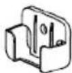 |
| Montažna ploča | 1 |  | Vijak za pričvršćivanje držača daljinskog upravljača (opcionalno) | 2 | 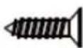 |
| Tiplovi | 5~8 (ovisno o modelu) | 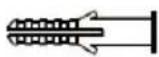 | Mali filter (potrebno je da ga ovlašteni tehničar instalirati na stražnju stranu glavnog zračnog filtera prilikom instaliranja stroja) | 5~8 (ovisno o modelu) |  |
| Vijci za pričvršćivanje montažne ploče | 5~8 (ovisno o modelu) | 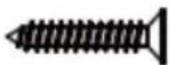 |
| Naziv | Oblik | Količina | |
| Priključni sklop cijevi | Tekućina | 6.35 (1/4in) | Dijelove morate kupiti zasebno. Posavjetujte se s dobavljačem o ispravnoj veličini cijevi jedinice koju ste kupili. |
| 9.52 (3/8in) | |||
| Gas | 9.52 (3/8in) | ||
| 12.7 (1/2in) | |||
| 16 (5/8in) | |||
| 19 (3/4in) | |||
| Magnetski prsten i remen (Ako je isporučeno, pogledajte dijagram ožičenja kako biste ga instalirali na spojni kabel.) |  |  Provucite pojas kroz otvor magnetskog prstena da biste ga pričvrstili na kabel Provucite pojas kroz otvor magnetskog prstena da biste ga pričvrstili na kabel | Ovisno o modelu |
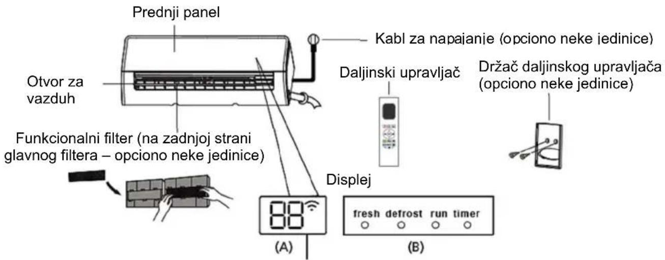
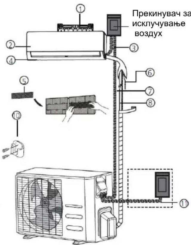
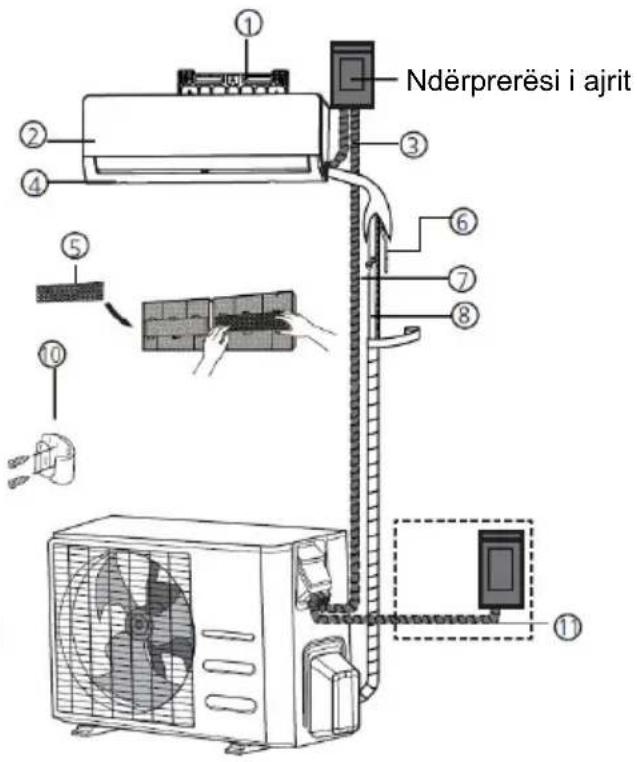
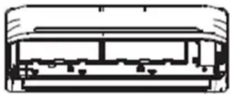
DIJELOVI GLAVNE JEDINICE
(1)
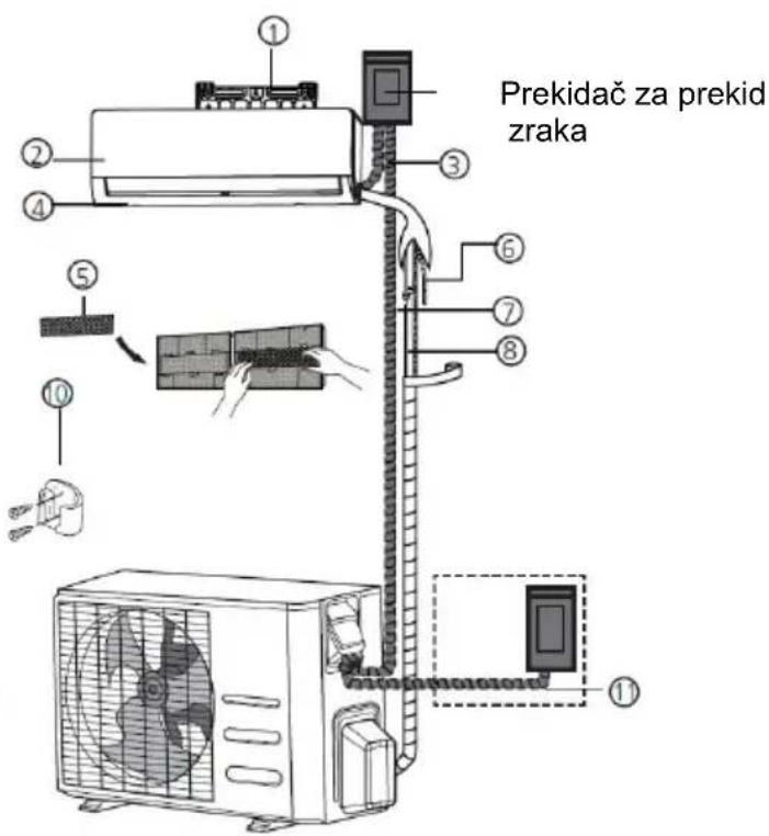
(2)
① Zidna montažna ploča
② Prednja ploča
③ Kabel za napajanje (neke jedinice)
④ Otvor za zrak
⑤ Funkcionalni filter (na stražnjoj strani glavnog filtra - neke jedinice)
⑥ Odvodna cijev
⑦ Signalni kabel
⑧ Cijevi rashladne tekućine
⑨ Daljinski upravljač
⑩ Držač daljinskog upravljača (neke jedinice)
⑪ Kabel za napajanje vanjske jedinice (neke jedinice)
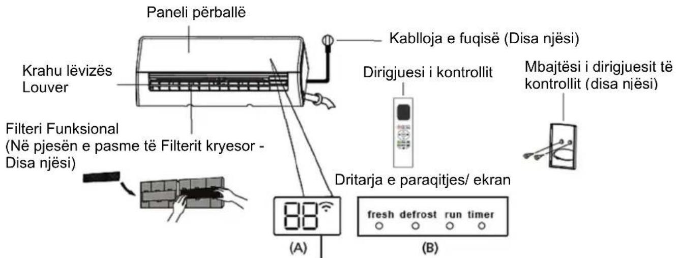
NAPOMENA O ILUSTRACIJAMA
Ilustracije u ovom priručniku služe za objašnjenje. Stvarni oblik vaše unutarnje jedinice može se blago razlikovati. Predstavljeni oblik će prevladati.
DIGITALNI ZASLON - OBJAŠNJENJE
| Model Kapacitet (BTU/h) | Maksimalna duljina (m) | Maksimalan pad (m) | |
| R410A,R32 Inverter Split klima uređaj | < 15,000 25m (82ft) 10m (33ft) | ||
| ≥ 15,000 and < 24,000 | 30m (98.5ft) | 20m (66ft) | |
| ≥ 24,000 and < 36,000 50m (164ft) 25m (82ft) | |||
| R22 klima uređaj fiksne brzine | < 18,000 10m (33ft) 5m (16ft) | ||
| ≥ 18,000 and < 21,000 | 15m (49ft) | 8m (26ft) | |
| ≥ 21,000 and < 35,000 20m (66ft) 10m (33ft) | |||
| R410A, R32 klima uređaj fiksne brzine | < 18,000 20m (66ft) 8m (26ft) | ||
| ≥ 18,000 and < 36,000 25m (82ft) 10m (33ft) | |||
Napomena o dodavanju rashladnog sredstva
natural_image
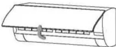
Simple line drawing of a hand cleaning a cylindrical object (no text or symbols)■ Odstranite filter zraka
natural_image
Line drawing of a cylindrical device with a flat top and internal slots, no text or symbols present.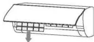
natural_image
Diagram of a car air conditioner unit with cooling fins and airflow direction arrow (no text or labels)natural_image
Illustration of a hand using a tool to clean a grid-patterned surface next to a bottle and bowl (no text or symbols)natural_image
Diagram of a car air conditioner unit with airflow direction indicated (no text or symbols)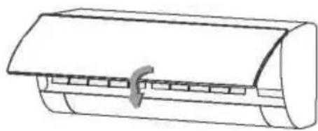
natural_image
Line drawing of a cylindrical mechanical component with a clasp (no text or symbols)Izvođenje operacija
- Način rada: AUTO, COOL (Hlađenje), DRY (Odvlaživanje), HEAT (Grijanje) ili FAN (Ventilacija).
- Postavljanje TIMER-a (vremenskog brojača) na 24 h.
- Postavljanje unutarnje temp. u rasponu: 17°C\~30°C.
- Funkcija LCD ekrana (Liquid Crystal Display – tekući kristalni zaslon).
PAŽNJA:
- Dizajn gumba može biti malo drugačiji od onoga koji ste vi zapravo kupili, ovisi o individualnim modelima.
- Sve opisane funkcije se ostvaruju preo unutarnje jedinice.
- Ako unutarnja jedinica nema ova svojst va, neće se obaviti odgovarajuće komande za koje ste pritisnuli gumb na daljinskom upravljaču.
Funkcije tipki
flowchart
graph TD
    A["1"] --> B["+"]
    B --> C["Mode"]
    C --> D["6"]
    D --> E["7"]
    F["2"] --> G["^"]
    H["3"] --> I["SET"]
    I --> J["OK"]
    J --> K["8"]
    K --> L["9"]
    M["2"] --> N["✓"]
    O["4"] --> P["Switch"]
    P --> Q["Fresh"]
    Q --> R["10"]
    S["5"] --> T["Turbo"]
    T --> U["LED"]
    U --> V["Clean"]
    V --> W["12"]
    X["13"] --> Y["13"]
1.ON/OFF Tipka
Radnja s pokreće kada se pritisne ovaj gumb te se radnja zaustavlja kada se pritisne ovaj gumb ponovno.
2. TEMP ▲ / ▼ Tipka
Povećava ili smanjuje temperaturu za 1°C. Maksimalna temp. je 30°C.
3. SET Tipka
Pažnja:
Svi indikatori prikazani na slici su u svrhu jasne prezentacije. No tijekom stvarnog rada na zaslonu se prikazuju samo relativni indikatori.
1.Prikaz dodatnih funkcija
S lijeva na desno:
-
Fresh prikaz funkcije Ne prikazuje se kad je funkcija Fresh aktivirana.
-
Sleep prikaz funkcije
-
ECO prikaz funkcije
-
Wi-Fi prikaz funkcije
-
Niska razina baterijena bljeska.
2. Prikaz funkcija
Prikazuje trenutni način rada. Uključuje AUTO Ⓐ, HLAĐENJE *, ODVLAŽIVANJE GRIJANJE , BRZINU VENTILACIJE i ponovo AUTO.
3. ECO Display
AUTO:
U AUTO načinu rada, uređaj će automatski odabrati hlađenje, brzinu ventilacije ili grijanje, ovisno o postavljenoj temperaturi.
- Pritisnite tipku MODE kako biste odabrali
automatski način.
Hlađenje/ Grijanje/ Ventilator
FRESH → SLEEP → FOLLOW ME → AP mode
Fresh funkcija
natural_image
Line drawing of a wall-mounted air conditioner unit with a control panel attached (no text or symbols)natural_image
Illustration of a hand holding two electronic devices with arrows indicating process flow (no text or symbols)natural_image
Diagram showing a wrench crossed with a screwdriver and a gear with a magnifying glass, connected to a triangular warning symbol (no text or labels)OPREZ: Opasnost od požara / zapaljivih materijala. Samo za R32 jedinice.
SADRŽAJ
Rad i održavanje
Upozorenje 3
Mere sigurnosti 4
Napomene za upotrebu 10
natural_image
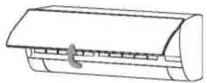
Technical line drawing of a mechanical fan or vent with grid pattern and wheels (no text or symbols)Molimo da pregledate da li je instalirani nosač dovoljno čvrst. Ako je oštećen, to može dovesti do pada jedinice i uzrokovati povredu.
natural_image
Illustration of a microwave oven with three geometric shapes (cube, cube, sphere) and a 'NO!' button, no text or symbols present.natural_image
Illustration of a spray gun emitting vapor onto a wall-mounted air conditioner (no text or symbols)Nemojte otvarati prozore i vrata na duže vreme kada radi uređaj za klimatizaciju. U suprotnom je moguće slabljenje kapaciteta hlađenja i grejanja.
Nemojte stajati na vrhu spoljašnje jedinice ili stavljati teške stvari na njih. Ovo može uzrokovati povrede ili oštetiti aparat.
natural_image
Cross-sectional diagram of a vehicle showing internal components (no text or labels)AUTO/COOL Ručni prekidač
natural_image
Line drawing of two hands pressing down on a rectangular panel (no text or symbols)(1)
(2)
① Zidna montažna ploča
② Unutrašnja jedinica – prednji panel
③ Kabl za napajanje
④ Otvor za vazduh
⑤ strani glavnog filtera – opciono neke jedinice)
⑥ Odvodna cev
⑦ Signalni kabl
⑧ Cevi za povezivanje jedinica
⑨ Daljinski upravljač
⑩ Držač daljinskog upravljača (neke jedinice)
⑪ Kabl za napajanje spoljašnje jedinice (opciono neke jedinice)
NAPOMENA O ILUSTRACIJAMA
Ilustracije u ovom uputstvu služe za objašnjenje. Stvarni oblik vaše unutrašnje jedinice može se delimično razlikovati.
DIGITALNI DISPLEJ - OBJAŠNJENJE
| Model Kapacitet (BTU/h) | Maksimalna dužina (m) | Maksimalan pad (m) | |
| R410A,R32 Inverter Split klima uređaj | < 15,000 25m (82ft) 10m (33ft) | ||
| ≥ 15,000 and < 24,000 | 30m (98.5ft) | 20m (66ft) | |
| ≥ 24,000 and < 36,000 | 50m (164ft) 25m (82ft) | ||
| R22 klima uređaj fiksne brzine | < 18,000 10m (33ft) 5m (16ft) | ||
| ≥ 18,000 and < 21,000 | 15m (49ft) | 8m (26ft) | |
| ≥ 21,000 and < 35,000 | 20m (66ft) 10m (33ft) | ||
| R410A, R32 klima uređaj fiksne brzine | < 18,000 20m (66ft) 8m (26ft) | ||
| ≥ 18,000 and < 36,000 | 25m (82ft) 10m (33ft) | ||
Napomena o dodavanju rashladnog sredstva
Neki sistemi zahtevaju dodatno punjenje zavisno od dužine cevi. Standardna dužina cevi varira u skladu s lokalnim propisima. Na primer, u Severnoj Americi standardna dužina cevi je 7,5 m (25'). U drugim područjima standardna dužina cevi je 5 m (16'). Rashladno sredstvo treba puniti iz servisnog priključka na ventilu niskog pritiska spoljašnje jedinice. Dodatno rashladno sredstvo za punjenje može se izračunati pomoću sledeće formule:
DODATNO RASHLADNO SREDSTVO PO DUŽINI CEVI
| Dužina spojne cevi (m) | Metoda pročišćavanja vazduha | Dodatno rashladno sredstvo | |
| ≤ Standardna dužina cevi | Vakuumska pumpa | N/A | |
| > Standardna dužina cevi | Vakuumska pumpa | Tekuća strana: ∅ 6.35 (∅ 0.25")R32:(Dužina cevi - standardna dužina) x 12g/m(Dužina cevi - standardna dužina) x 0.13oZ/ftR290:(Dužina cevi - standardna dužina) x 10g/m(Dužina cevi - standardna dužina) x 0.10oZ/ftR410A:(Dužina cevi - standardna dužina) x 15g/m(Dužina cevi - standardna dužina) x 0.16oZ/ftR22:(Dužina cevi - standardna dužina) x 20g/m (Dužina cevi - standardna dužina) x 0.21oZ/ft | Tekuća strana: ∅ 9.52 (∅ 0.375")R32:(Dužina cevi - standardna dužina) x 24g/m(Dužina cevi - standardna dužina) x 0.26oZ/ftR290:(Dužina cevi - standardna dužina) x 18g/m (Dužina cevi - standardna dužina) x 0.19oZ/ftR410A:(Dužina cevi - standardna dužina) x 30g/m (Dužina cevi - standardna dužina) x 0.32oZ/ftR22:(Dužina cevi - standardna dužina) x 40g/m(Dužina cevi - standardna dužina) x 0.42oZ/ft |
Za rashladnu jedinicu R290, ukupna količina rashladnog sredstva za punjenje nije veća od: 387g (<=9000Btu/h), 447g (>9000Btu/h and <=12000Btu/h), 547g (>12000Btu/h and <=18000Btu/h), 632g (>18000Btu/h and <=24000Btu/h).

OPREZ: NE mešajte različite tipove rashladnog sredstva.
natural_image
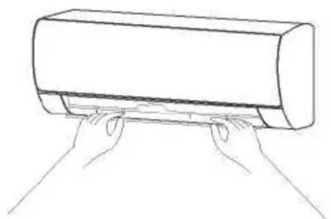
Simple line drawing of a hand using a power tool to clean or brush the sheet of paper (no text or symbols)Čišćenje filtera vazduha
■ Odstranite filter vazduha
natural_image
Simple line drawing of a cylindrical object with a handle and internal structure (no text or symbols)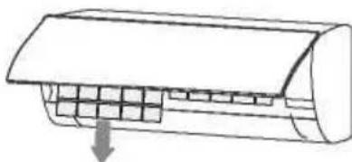
natural_image
Diagram of a car air conditioner unit with cooling fins and airflow direction arrow (no text or labels)-
Koristite obe ruke kako bi otvorili ploču za ugao s oba kraja ploče u skladu sa smerom strelice.
-
Otpustite filter vazduha iz žleba i odstranite ga.
■ Očistite filter vazduha
natural_image
Illustration of a car being cleaned on a grid paper next to a washing bottle and bowl (no text or symbols)natural_image
Diagram of a car air conditioner unit with airflow arrow indicating down (no text or symbols)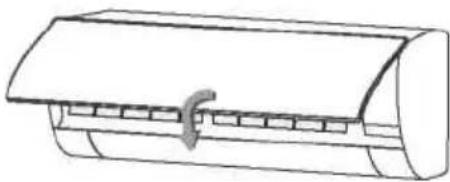
natural_image
Line drawing of a cylindrical air conditioner unit with a handle (no text or symbols)Proverite pre upotrebe
- Proverite jesu li ulazi i izlazi vazduha aparata slobodni.
- Proverite je li izlaz vode na cevi za ispust blokiran i odmah ga očistite ako jeste.
- Proverite je li žica za uzemljenje pouzdano uzemljena.
- Proverite jesu li baterije daljinskog upravljača instalirane i je li njihovo punjenje dovoljno.
- Proverite postoje li oštećenja na rešetki za instalaciju spoljašnje jedinice i, ako postoje, molimo da kontaktirate naš lokalni servisni centar.
Održavanje nakon upotrebe
- Isključite izvor energije aparata, isključite glavni strujni prekidač i odstranite baterije iz daljinskog upravljača.
- Očistite filter i telo aparata.
- Odstranite prašinu i talog sa spoljašnje jedinice.
- Proverite postoje li oštećenja na rešetki za instalaciju spoljašnje jedinice i, ako postoje, molimo da kontaktirate naš lokalni servisni centar.
Rešavanje problema
Pažnja
Nemojte samostalno popravljati klima uređaj budući da krivo održavanje može uzrokovati elektrošok, požar ili eksploziju. Molimo da kontaktirate naš ovlašćeni servisni centar i prepustite održavanje profesionalcima i proverite sledeće stvari pre kontaktiranja servisa kako bi uštedeli vreme i novac.
Fenomen
Izvođenje operacija
- Način rada: AUTO, COOL (Hlađenje), DRY (Odvlaživanje), HEAT (Grejanje) ili FAN (Ventilacija).
- Postavljanje TIMER-a (vremenskog brojača) na 24 h.
- Postavljanje unutrašnje temp. u rasponu: 17°C\~30°C.
- Funkcija LCD ekrana (Liquid Crystal Display – tečni kristalni ekran).
PAŽNJA:
- Dizajn tastera može biti malo drugačiji od onog koji ste vi zapravo kupili, zavisi o individualnim modelima.
- Sve opisane funkcije se ostvaruju preko unutrašnje jedinice.
- Ako unutrašnja jedinica ne ma ova svojstva, neće se obaviti odgovarajuće komande za koje ste pritisnuli taster na daljinskom upravljaču.
Funkcije tastera
flowchart
graph TD
    A["1"] --> B["Mode"]
    B --> C["6"]
    D["2"] --> E["IDE"]
    E --> F["7"]
    G["3"] --> H["SET OK"]
    H --> I["8"]
    J["4"] --> K["Turbo"]
    K --> L["5"]
    M["5"] --> N["Turbo"]
    N --> O["6"]
    P["6"] --> Q["Clean"]
    R["7"] --> S["Fresh"]
    T["8"] --> U["Fresh"]
    V["9"] --> W["Fresh"]
    X["10"] --> Y["Fresh"]
    Z["11"] --> AA["Fresh"]
    AB["12"] --> AC["Fresh"]
    AD["13"] --> AE["Fresh"]
1.ON/OFF Taster
Radnja s pokreće kada se pritisne ovaj taster te se radnja zaustavlja kada se pritisne ovaj taster ponovo.
2. TEMP ▲ / ▼ Taster
Povećava ili smanjuje temperaturu za 1°C. Maksimalna temp. je 30°C.
3. SET Taster
Kružni odabir Dodatnih funkcija: Prati me ( ⚙ ) → AP način
( → Prati me( ).
Odgovarajuća ikona odabrane funkcije svetleće na ekranu. Kako biste potvrdili, pritisnite taster OK.
4.FAN SPEED (Brzina ventilatora)
Koristite brzinu ventilatora u četiri koraka:
→ AUTO → LOW → MED → HIGH
5. TURBO Taster
Odvlaživanje
Pritisnite taster Swing.
- Horizontalni usmerivači vazduha će se pokretati gore/ dole automatski. Ponovo pritisnite kako biste prekinuli funkciju.
LED ekran
Pritisnite taster LED.
- Pritiskom na ovu taster uključiće / isključiće se ekran unutrašnje jedinice.
Funkcija tihog rada
FRESH → SLEEP → FOLLOW ME → AP mode
Fresh funkcija

natural_image
Line drawing of a car air conditioner unit with a handheld control panel (no text or symbols)natural_image
Illustration of a hand holding two electronic devices with arrows indicating process flow (no text or symbols)Sledeći simptomi su znak slabih baterija. Zamenite ih novima.
- Nema povratnog zvuka kada se stisne taster.
- Svetlo indikatora je slabo.
Daljinski upravljač radi pomoću dve suve baterije(R03/LR03X2) koje s nalaze u zadnjem delu i zaštićene su poklopcem.
(1) Uklonite poklopac tako što ćete pritisnuti l skliznuti poklopcem.
(2) Uklonite stare baterije i stavite nove baterije postavljajući plus(+) i minus(-) na za to određena mesta.
(3) Vratite poklopac kliznim pokretom na isto mesto.
PAŽNJA: Nakon uklanjanja starih baterija, daljinski upravljač briše sve programe,a nakon stavljanja novih baterija svi se programi moraju reprogramirati.

OPREZ
Nemojte mešati stare i nove baterije različitih vrsta.
Ne ostavljajte baterije u daljinskom upravljaču ako ih nećete koristiti sledeća dva ili tri meseca.
Ne bacajte baterije kao nerazvrstani gradski otpad. Skupini takvog otpada potreban je poseban tretman recikliranja.
natural_image
Diagram showing a wrench crossed with a screwdriver and a gear with a magnifying glass, connected by dotted lines to a triangular warning symbol (no text or labels)natural_image
Technical line drawing of a portable air conditioner unit with fan and wheels (no text or symbols)natural_image
Illustration of a toaster with three geometric shapes (cube, cube, sphere) and a 'NO!' label, no readable text or symbols beyond the label.natural_image
Illustration of a car air conditioner emitting vapor from a chimney (no text or symbols)natural_image
Simple line drawing of an open window with a curved arched top (no text or symbols)natural_image
Illustration of a vintage radio with floral decorations and a 'NO!' speech bubble (no text or symbols on the device itself)natural_image
Simple line drawing of a rectangular object with a diagonal line extending from its top, resembling a stylized air conditioner or container (no text or symbols)Поставете подобратемпература.
natural_image
Cross-sectional diagram of a mechanical or electrical component with layered structure (no text or symbols)natural_image
Line drawing of two hands pressing down on a cylindrical object (no text or symbols)Специфична грижа
(1)
natural_image
Simple line drawing of a hand cleaning a rectangular object (no text or symbols)natural_image
Line drawing of a cylindrical device with a handle and internal components (no text or symbols)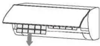
natural_image
Diagram of a car air conditioner unit with cooling fins and airflow direction arrow (no text or symbols)natural_image
Illustration of a hand using a tool to clean a grid-patterned object next to a bowl filled with cotton and a bottle (no text or symbols)Чистење и одржување
natural_image
Diagram of a car air conditioner unit with airflow arrow indicating airflow direction (no text or symbols)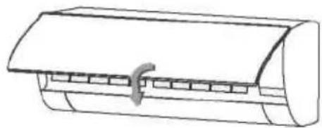
natural_image
Line drawing of a cylindrical air conditioner unit with a handle (no text or symbols)Карактеристика на перформанси
АВТОМАТСКИ РЕЖИМ:
natural_image
Line drawing of a wall-mounted air conditioner unit with a control panel attached (no text or symbols)natural_image
Illustration of a hand holding two rectangular devices with downward arrows indicating movement or change (no text or symbols present)The design and specifications are subject to change without prior notice for product improvement. Consult with the sales agency or manufacturer for details.
natural_image
Diagram showing a wrench crossed with a screwdriver and a gear with a magnifying glass, connected by dotted lines to a triangular warning symbol (no text or labels)natural_image
Simple line drawing of a rectangular block with a hand holding a explosion and an 'NO!' speech bubble (no text or symbols on the diagram itself)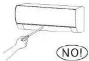
natural_image
Technical line drawing of a four-wheeled air fan with visible blades and wheels (no text or symbols)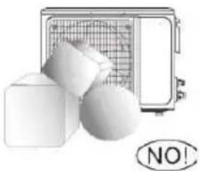
natural_image
Illustration of a portable device with a grid screen and two geometric shapes (no text or symbols)natural_image
Simple line drawing of a rectangular air conditioner emitting vapor from a steaming base (no text or symbols)natural_image
Simple line drawing of an open arched window with no text or symbolsnatural_image
Illustration of a vintage radio with floral decorations and a 'NO!' speech bubble (no text or symbols on the device itself)natural_image
Simple line drawing of a rectangular object with a diagonal line extending from its top, resembling a stylized arrow or pointer (no text or symbols)Vendosni temperaturën e duhur.
natural_image
Cross-sectional diagram of a mechanical or electrical component with layered structure (no text or symbols)AUTO/COOL SWITCH MANUAL
natural_image
Line drawing of two hands pressing down on a rectangular panel (no text or symbols)Kujdes specifik
(1)
Illustrations in this manual are for explanatory purposes. The actual shape of your indoor unit may be slightly different. The actual shape shall prevail.
SQARIMI I EKRANIT DIGJITAL
natural_image
Two 3D rectangular blocks with internal grid patterns and a white arrow pointing to one block (no text or symbols)Erë e fortë
natural_image
Simple line drawing of a hand cleaning a rectangular object (no text or symbols)natural_image
Line drawing of a cylindrical object with a handle and internal structure (no text or symbols)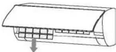
natural_image
Diagram of a car air duct with internal grid structure and downward arrow indicating airflow (no text or symbols)natural_image
Illustration showing a person using a cleaning tool on a grid paper and a bottle of soap in a basin (no text or symbols)natural_image
Diagram of a car air duct with internal grid structure and an upward arrow indicating airflow or movement (no text or symbols)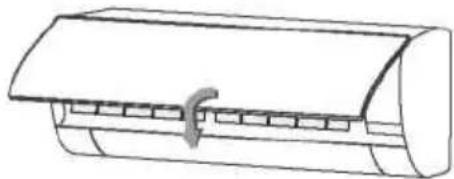
natural_image
Line drawing of a cylindrical air conditioner unit with a handle (no text or symbols)→ AUTO → LOW → MED → HIGH
5. Butoni TURBO
Funksionimi automatik
SHENIM
Veprimi
Dehumidifikues/Dehidratues
FRESH → SLEEP* → FOLLOW ME → AP mode
FRESKET→GJUME→ME NDIQ MUA→modaliteti AP
natural_image
Line drawing of a car air conditioner unit with control panel and fan (no text or symbols)natural_image
Illustration of a hand holding two remote control devices with arrows indicating movement (no text or symbols)natural_image
Symbol of a trash bin crossed out by two diagonal lines, no text or numbers presentnatural_image
Diagram showing a wrench crossed with a screwdriver and a gear with a magnifying glass, connected by dotted lines to a triangular warning symbol (no text or labels)POZOR: Nevarnost požara / vnetljivih materialov.
Samo za R32 enote.
VSEBINA
Delo in vzdrževanje
Opozorilo 3
Varnostni ukrepi 4
Opombe za uporabo 9
Imena vseh delov 12
Pazite, da ne zmočite no tranje enote.
natural_image
Technical line drawing of a mechanical fan or vent with no visible text or symbolsnatural_image
Cross-sectional diagram of a mechanical or electrical component with layered structure (no text or symbols)AUTO/COOL Ročno stikalo
natural_image
Line drawing of two hands pressing down on a rectangular panel (no text or symbols)(1)
(2)
natural_image
Simple line drawing of a hand using a power tool to clean or brush the next page of a cylindrical object (no text or symbols)natural_image
Simple line drawing of a cylindrical object with a handle, resembling a mechanical or electronic component (no text or symbols)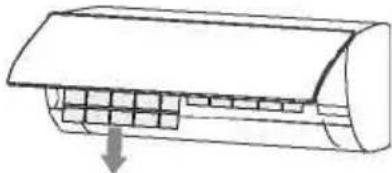
natural_image
Diagram of a car air conditioner unit with cooling fins and airflow direction arrow (no text or labels)natural_image
Illustration showing a car being cleaned on a grid paper next to a bowl of laundry (no text or symbols)Uporabite sesalec ali vodo da bi ga oprali, će je zelo umazan (npr. masten), ga očistite s toplo vodo (pod 45 ° C) in blagim detergentom, raztopljenim v vodi, nato pa filter v senci posušite na zraku.
Funkcija uspešnosti
V načinu AUTO bo enota samodejno izbrala delovanje COOL, FAN ali HEAT glede na nastavljeno temperaturo.
- Pritisnite gumb MODE, da izberete Auto.
- Pritisnite gumb ▲ / ▼, da nastavite želeno temperaturo. Temperaturo lahko nastavite v območju od 17 ° C do 30 ° C v korakih po 10 ° C.
- Pritisnite gumb ON / OFF, da zaženete klimatsko napravo.
OPOMBA
Pritisnite gumb Swing.
- Horizontalna loputa se bo samodejno zanihala gor in dol, ko pritisnete gumb Swing. Pritisnite še enkrat, da se ustavi.
LED zaslon
Pritisnite gumb LED.
- Pritisnite ta gumb, da vklopite in izklopite zaslon na notranji enoti.
Funkcija tišine
natural_image
Line drawing of a car air conditioner unit with a control panel and fan (no text or symbols)natural_image
Illustration of a hand holding two handheld devices with downward arrows indicating movement or change (no text or symbols present)POZOR
natural_image
Pure electrical circuit lines without any symbolsnatural_image
Diagram showing a wrench crossed with a screwdriver and a gear with a magnifying glass, connected by dotted lines to a triangular warning symbol (no text or labels)CAUTION: Risk of fire/ flammable materials. FOR R32 units only.
CONTENTS
Operation and maintenance
Warning 3
Safety Precautions 4
Notices for use 9
Names of each part 12
Clean and care 13
Troubleshooting 15
Note: All the pictures in this manual are just schematic diagrams, the actual is the standard.
Warning
Warning: This air conditioner uses R32 flammable refrigerant.
Notes: Air conditioner with R32 refrigerant, if roughly treated, may cause serious harm to the human body or surrounding things.
* The room space for the installation, use, repair, and storage of this air conditioner should be greater than 5m.
* Air conditioner refrigerant can not charge more than 1.7kg.
* Do not use any methods to speed up defrost or to clean frosty parts except for particular recommended by manufacturer.
* Not pierce or burn air conditioner, and check the refrigerant pipeline wether be damaged.
* The air conditioner should be stored in a room without lasting fire source, for example, open flame, burning gas appliance, working electric heater and so on.
* Notice that the refrigerant may be tasteless.
* The storage of air conditioner should be able to prevent mechanical damage caused by accident.
* Maintenance or repair of air conditioners using R32 refrigerant must be carried out after security check to minimize risk of incidents.
* Air conditioner must be installed with stop valve cover.
* Please read the instruction carefully before installing, using and maintaining.
Symbol
Note
Explanation
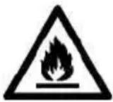
WARNING
This symbol shows that this appliance uses a flammable refrigerant. If the refrigerant is leaked and exposed to an external ignition source, there is a risk of fire
CAUTION
This symbol shows that the operation manual should be read carefully.
CAUTION
This symbol shows that a service personnel should be handling this equipment with reference to the installation manual.
CAUTION
This symbol shows that information is available such as the operating manual or installation manual
Safety precautions
Incorrect installation or operation by not following these instructions may cause harm or damage to people, properties, etc.
The seriousness is classified by the following indications:
WARNING

This symbol indicates the possibility of death or serious injury.
CAUTION

This symbol indicates the possibility of injury or damage to properties.
WARNING

This appliance can be used by children aged from 8 years and above and persons with reduced physical, sensory or mental capabilities or lack of experience and knowledge if they have been given supervision or instruction concerning use of the appliance in a safe way and understand the hazards involved. Children shall not play with the appliance. Cleaning and user maintenance shall not be made by children without supervision.
Safety Precautions

The air conditioner must be grounded. Incomplete grounding may result in electric shocks.
Do not connect the earth wire to the gas pipeline, water pipeline, lightning rod, or telephone earth wire.
Always switch off the device and cut the power supply when the unit is not in use for long time so as to ensure safety.
Take care not let the remote control and the indoor unit watered or being too wet.
Otherwise, it may cause short circuit
If the power supply cable is damaged, it must be replaced by the manufacture or its service agent or a similar qualified person.
Don't cut off main power switch during operating or with wet hands.
It may cause electric shock.
Don't share the socket with other electric appliance. It may cause electric shock.
Always switch off the device and cut the power supply before performing any maintenance or cleaning.
Otherwise, it may cause electric shock or damage.
Don't pull the power cable.
The damage of pulling power cord will cause serious electric shock.
Pay attention that ducts connected to an appliance shall not contain an ignition source.
Safety Precautions
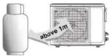
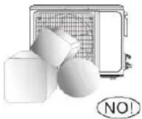
Don't install air conditioner in a place where there is flammable gas or liquid. The distance between them should above 1m. It may cause fire even explosion.
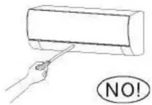
Don't use liquid or corrosive cleaning agent wipe the air conditioner and sprinkle water or other liquid either. Doing this may cause electric shock or damage to the unit.
Don't attempt to repair the air conditioner by yourself. Incorrect repairs may cause fire or explosion. Contact a qualified service technician for all service requirement.
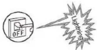
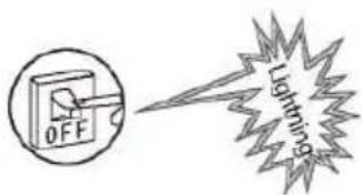
Don't use air conditioner in lightning strom weather. Power supply should be cut in time to prevent the occurrence of danger.
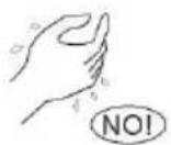
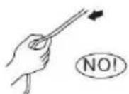
Don't put hands or any objects into the air inlets or outlets. This may cause personal injury or damage to the unit.
natural_image
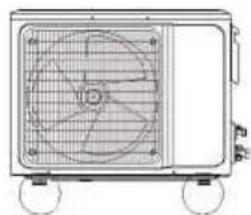
Technical line drawing of a fan or air conditioner unit with visible blades and wheels (no text or symbols)Please note whether the installed stand is firm enough or not. If it is damaged, it may lead to the fall of the unit and cause the injury.
natural_image
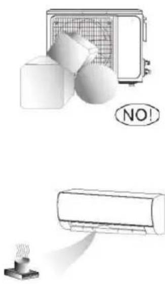
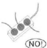
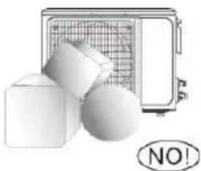
Illustration of a portable air conditioner unit with three geometric shapes (cube, cube, sphere) and a 'NO!' button below (no text or symbols on main objects)Don't block air inlet or air outlet. Otherwise, the cooling or heating capacity will be weakened, even cause system stop operating
natural_image
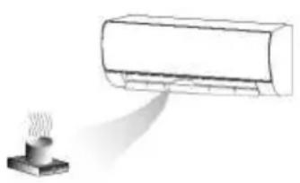
Illustration of a car air conditioner emitting exhaust smoke from a chimney (no text or symbols)Don't let the air conditioner blow against the heater appliance. Otherwise it will lead to incomplete combustion, thus causing poisoning
The appliance shall be installed in accordance with national wiring regulations.
An earth leakage breker with rated capacity must be installed to avoid possible electric shocks.
Safety Precautions
This product contains fluorinated greenhouse gases.
Refrigerant leakage contributes to climate change. Refrigerant with lower global warming potential (GWP) would contribute less to global warming than a refrigerant with higher GWP, if leaked to the atmosphere. This appliance contains a refrigerant fluid with a GWP equal to [675] . This means that if 1 kg of this refrigerant fluid would be leaked to the atmosphere, the impact on global warming would be [675] times higher than 1 kg of CO2, over a period of 100 years. Never try to interfere with the refrigerant circuit yourself or disassemble the product yourself and always ask a professiona.
Ensure no following objects under the indoor unit:
- microwaves, ovens and other hot objects.
- computers and other high electrostatic appliances.
- sockets that plug frequently.
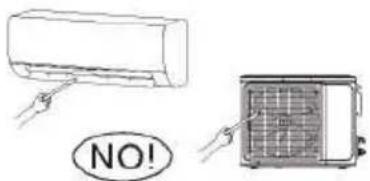
The joints between indoor and outdoor unit shall not be reused, unless after reflaring the pipe.
The specification of the fuse are printed on the circuit bord, such as: 3.15A/250V AC, etc.
Safety Precautions
natural_image
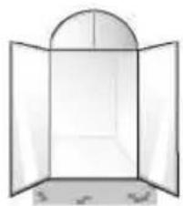
Simple line drawing of an open window with a curved arched top (no text or symbols)Don't open the windows and doors for long time when the air conditioner is running.
Otherwise, the cooling or heating capacity will be weakened.
natural_image
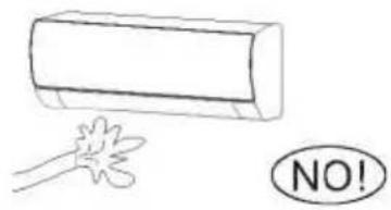
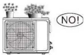
Illustration of a vintage radio with two potted plants and a 'NO!' speech bubble (no text or symbols on the device itself)Don't stand on the top of the outdoor unit or place heavy things on it. This cloud cause personal injuries or damage the unit.
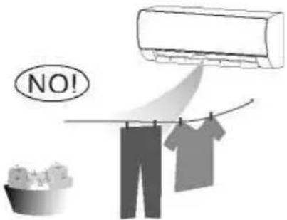
Don't use the air conditioner for other purposes, such as drying clothes, preserving foods, etc.
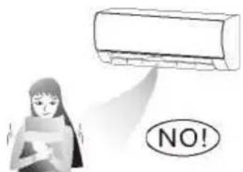
Don't apply the cold air to the body for a long time.
It will deteriorate your physical conditions and cause health problems.
natural_image
Simple line drawing of a rectangular object with a curved arrow pointing downward (no text or symbols)Set the suitable temperature.
It is recommended that the temperature difference between indoor and outdoor temperature should not be too large.
Appropriate adjustments of the setting temperature can prevent the waste of electricity.
If your air conditioner is not fitted with a supply cord and a plug, an anti-explosion all-pole switch must be installed in the fixed wiring and the distance between contacts should be no less than 3.0 mm.
If your air conditioner is permanently connected to the fixed wiring, a anti-explosion residual current device (RCD) having rated residual operating current not exceeding 30 mA should be installed in the fixed wiring.
The power supply circuit should have leakage protector and air switch of which the capacity should be more than 1.5 times of the maximum current.
Regarding the installation of the air conditioners, please refer to the below paragraphs in this manual.
Notices for use
The conditions of unit can't normally run
Within the temperature range provided in following table, the air conditioner may stop running and other anomalies may arise.
| Cool | Outside | >43 °C (Applicable for T1) |
| >52 °C (Applicable for T3) | ||
| Inside <18 °C | ||
| Heat | Outside | >24 °C |
| <-7 °C | ||
| Inside >27 °C | ||
* When the temperature is too high, the air conditioner may activate the automatic protection device, so that the air conditioner could be shut down.
* When the temperature is too low, the heat exchanger of the air conditioner may freeze, leading to water dripping or other malfunction.
* In long-term cooling or dehumidification with a relative humidity of above 80% (doors and windows are open), there may be water condenses or dripping near the air outlet.
* T1 and T3 refer to ISO 5151.
Notes for heating
* The fan of the indoor unit will not start running immediately after the heating is started to avoid blowing out cool air.
* When it is cold and wet outside, the outdoor unit will develop frost over the heat exchanger which will increase the heating capacity. Then the air conditioner will start defrost function.
* During defrost, the air conditioner will stop heating for about 5-12 minutes.
* Vapor may come out from the outdoor unit during defrost. This is not a malfunction, but a result of fast defrost.
* Heating will resume after defrost is complete.
Notes for turning off
When the air conditioner is turned off, the main controller will automatically decide whether to stop immediately or after running for dozens of seconds with lower frequency and lower air speed.
Notices for use
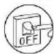
Emergency operation
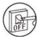
* If the remote controller is lost or broken, use force switch button to operate the air conditioner.
* If this button is pushed with the unit OFF, the air conditioner will operate in Auto mode.
* If you press the switch twice within five seconds, the unit will operate under forced COOL operation.
natural_image
Cross-sectional diagram of a mechanical or electrical component with layered structure (no text or symbols)AUTO/COOL Manual Switch
NOTE: Picture is for reference only. The force switch button may be located somewhere near the place like on the picture.
Airflow direction adjustment
- Use up-down swing and left-right swing buttons on the remote controller to adjust the airflow direction. Refer to the operation manual of the remote controller for detail.
- For models without left-right swing function, the fins has to be moved manually.
Note: Move the fins before the unit is in operation, or your finger might be injured.
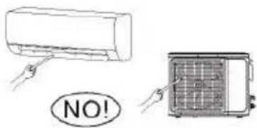
Never place your hand into the air inlet or outlet when the air conditioner is in operation.
natural_image
Line drawing of two hands pressing down on a rectangular object (no text or symbols)Accessories
The air conditioning system comes with the following accessories. Use all of the installation parts and accessories to install the air conditioner. Improper installation may result in water leakage, electrical shock and fire, or cause the equipment to fail. The items are not included with the air conditioner must be purchased separately.
| Name of Accessories Q'ty(pc) Shape | Name of Accessories Q'ty(pc) Shape | ||||
| Manual | 2~3 |  | Remote controller | 1 |  |
| Drain joint (for cooling & heating models) | 1 |  | Battery | 2 |  |
| Seal (for cooling & heating models) | 1 |  | Remote controller holder (optional) | 1 |  |
| Mounting plate | 1 | 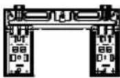 | Fixing screw for remote controller holder (optional) | 2 |  |
| Anchor | 5~8 (depending on models) |  | Small Filter (Need to be installed on the back of main air filter by the authorized technician while installing the machine) | 5~8 (depending on models) |  |
| Mounting plate fixing screw | 5~8 (depending on models) |  | |||
| Name Shape Quantity (PC) | |||
| Connecting pipe assembly | Liquid side | Φ 6.35 (1/4in) | Parts you must purchase separately. Consult the dealer about the proper pipe size of the unit you purchased. |
| Φ 9.52 (3/8in) | |||
| Gas side | Φ 9.52 (3/8in) | ||
| Φ 12.7 (1/2in) | |||
| Φ 16 (5/8in) | |||
| Φ 19 (3/4in) | |||
| Magnetic ring and belt(If supplied, please refer to the wiring diagram to install it on the connective cable.) | 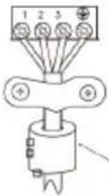 |  Pass the belt through the hole of the Magnetic ring to fix it on the cable Pass the belt through the hole of the Magnetic ring to fix it on the cable | Varies by model |
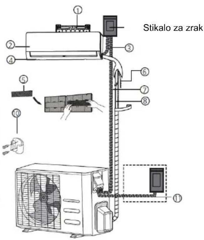
MAIN UNIT PARTS
Note: The installation must be performed in accordance with the requirement of local and national standards. The installation may be slightly different in different areas.
(1)
(2)
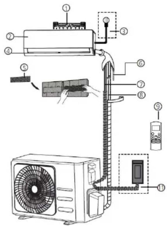
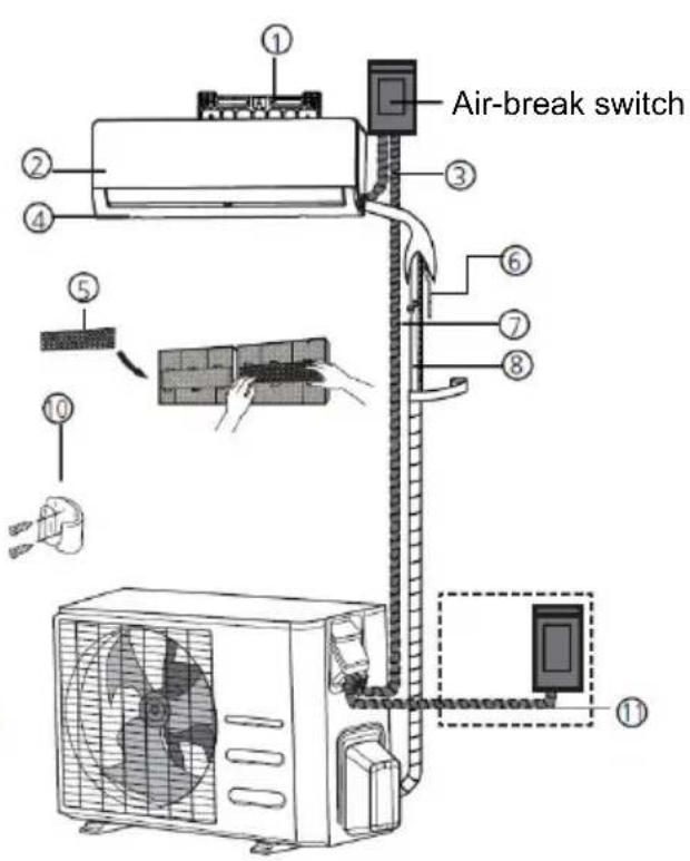
① Wall Mounting Plate
② Front Panel
③ Power Cable (Some units)
④ Louver
⑤ Functional Filter (On Back of Main Filter - Some Units)
⑥ Drainage Pipe
⑦ Signal Cable
⑧ Refrigerant Piping
⑨ Remote Controller
⑩ Remote controller Holder (Some Units)
⑪ Outdoor Unit Power Cable (Some Units)
NOTE ON ILLUSTRATIONS
Illustrations in this manual are for explanatory purposes. The actual shape of your indoor unit may be slightly different. The actual shape shall prevail.
DIGITAL DISPLAY EXPLANATION
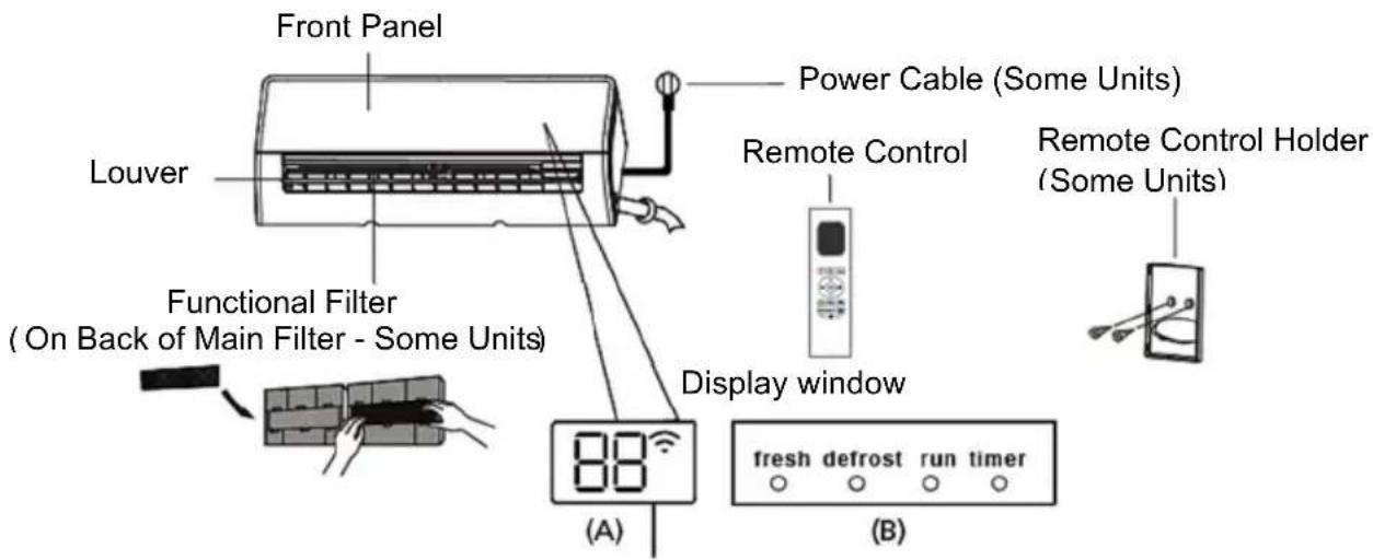
"Fresh" when Fresh and UV-C lamp (if any) feature is activated (some units)
"Defrost" when defrost feature is activated.
"Run" when the unit is on
"Timer" when timer is set
“ ^2 ”when Wireless Control feature is activated (some units)
“88 displays temperature, operation feature and error codes:
“”for 3 seconds when:
• TIMER ON is set (if the ON unit is OFF, emains on when TIMER ON is set)
- FRESH, UV-C lamp, SWING, TURBO, ECO, or SILENCE feature is turned on
“”for 3 seconds when:
- TIMER OFF is set
• FRESH, UV-C lamp, SWING, TURBO, ECO, or SILENCE feature is turned off
“df when defrosting
“” when 8 C heating feature is turned on (some units)
“”when Active Clean feature is turned on (For Inverter split type) when unit is self-cleaning(For Fixed-speed type)
Indoor Unit Installation
Installation Instructions – Indoor unit
PRIOR TO INSTALLATION
Before installing the indoor unit, refer to the label on the product box to make sure that the model number of the indoor unit matches the model number of the outdoor unit.
Step 1: Select installation location
Before installing the indoor unit, you must choose an appropriate location.
The following are standards that will help you choose an appropriate location for the unit.
Proper installation locations meet the following standards:
√ Good air circulation
√ Convenient drainage
√ Noise from the unit will not disturb other people
√ Firm and solid—the location will not vibrate
√ Strong enough to support the weight of the unit
√ A location at least one meter from all other electrical devices (e.g., TV, radio, computer)
DO NOT install unit in the following locations:
× Near any source of heat, steam, or combustible gas
× Near flammable items such as curtains or clothing
× Near any obstacle that might block air circulation
× Near the doorway
× In a location subject to direct sunlight
NOTE ABOUT WALL HOLE:
If there is no fixed refrigerant piping:
While choosing a location, be aware that you should leave ample room for a wall hole (see Drill wall hole for connective piping step) for the signal cable and refrigerant piping that connect the indoor and outdoor units. The default position for all piping is the right side of the indoor unit (while facing the unit). However, the unit can accommodate piping to both the left and right.
!
BEFORE PERFORMING ANY ELECTRICAL WORK, READ THESE REGULATIONS
-
All wiring must comply with local and national electrical codes, regulations and must be installed by a licensed electrician.
-
All electrical connections must be made according to the Electrical Connection Diagram located on the panels of the indoor and outdoor units.
-
If there is a serious safety issue with the power supply, stop work immediately. Explain your reasoning to the client, and refuse to install the unit until the safety issue is properly resolved.
-
Power voltage should be within 90-110% of rated voltage. Insufficient power supply can cause malfunction, electrical shock, or fire.
-
If connecting power to fixed wiring, a surge protector and main power switch should be installed.
-
If connecting power to fixed wiring, a switch or circuit breaker that disconnects all poles and has a contact separation of at least 1/8in (3mm) must be incorporated in the fixed wiring. The qualified technician must use an approved circuit breaker or switch.
-
Only connect the unit to an individual branch circuit outlet. Do not connect another appliance to that outlet.
-
Make sure to properly ground the air conditioner.
-
Every wire must be firmly connected. Loose wiring can cause the terminal to overheat, resulting in product malfunction and possible fire.
-
Do not let wires touch or rest against refrigerant tubing, the compressor, or any moving parts within the unit.
-
If the unit has an auxiliary electric heater, it must be installed at least 1 meter (40in) away from any combustible materials.
-
To avoid getting an electric shock, never touch the electrical components soon after the power supply has been turned off. After turning off the power, always wait 10 minutes or more before you touch the electrical components.

WARNING
BEFORE PERFORMING ANY ELECTRICAL OR WIRING WORK, TURN OFF THE MAIN POWER TO THE SYSTEM.
Connect signal and power cables
The signal cable enables communication between the indoor and outdoor units. You must first choose the right cable size before preparing it for connection.
Cable Types
- Indoor Power Cable (if applicable): H05VV-F or H05V2V2-F
• Outdoor Power Cable: H07RN-F or H05RN-F
• Signal Cable: H07RN-F
NOTE: In North America, choose the cable type according to the local electrical codes and regulations.
Minimum Cross-Sectional Area of Power and Signal Cables (For reference) (Not applicable for North America)
| Rated Current of Appliance (A) | Nominal Cross-Sectional Area (mm2) |
| >3 and ≤6 0.75 | |
| >6 and ≤10 1 | |
| >10 and ≤16 1.5 | |
| >16 and ≤25 2.5 | |
| >25 and ≤32 4 | |
| >32 and ≤40 6 |
Outdoor Unit Installation
Install the unit by following local codes and regulations, there may be differ slightly between different regions.
Installation Instructions – Outdoor unit
Step 1: Select installation location
Before installing the outdoor unit, you must choose an appropriate location.
The following are standards that will help you choose an appropriate location for the unit.
Proper installation locations meet the following standards:
√ Meets all spatial requirements shown in Installation Space Requirements above.
√ Good air circulation and ventilation
√ Firm and solid—t he location can support the unit and will not vibrate
√ Noise from the unit will not disturb others
√ Protected from prolonged periods of direct sunlight or rain
√ Where snowfall is anticipated, take appropriate measures to prevent ice buildup and coil damage.
DO NOT install unit in the following locations:
× Near an obstacle that will block air inlets and outlets
× Near a public street, crowded areas, or where noise from the unit will disturb others. Near animals or plants that will be harmed by hot air discharge
× Near any source of combustible gas
× In a location that is exposed to large amounts of dust
✗ In a location exposed to a excessive amounts of salty air
If the unit is exposed to heavy wind: Install unit so that air outlet fan is at a 90° angle to the direction of the wind. If needed, build a barrier in front of the unit to protect it from extremely heavy winds. See Figures below.
If the unit is frequently exposed to heavy rain or snow:
Build a shelter above the unit to protect it from the rain or snow. Be careful not to obstruct air flow around the unit.
If the unit is frequently exposed to salty air (seaside):
Use outdoor unit that is specially designed to resist corrosion.
Refrigerant Piping Connection
When connecting refrigerant piping, do not let substances or gases other than the specified refrigerant enter the unit. The presence of other gases or substances will lower the unit's capacity, and can cause abnormally high pressure in the refrigeration cycle. This can cause explosion and injury.
Note on Pipe Length
The length of refrigerant piping will affect the performance and energy efficiency of the unit. Nominal efficiency is tested on units with a pipe length of 5 meters (16.5ft)( In North America, the standard pipe length is 7.5m (25’)). A minimum pipe run of 3 metres is required to minimise vibration & excessive noise. In special tropical area, for the R290 refrigerant models, no refrigerant can be added and the maximum length of refrigerant pipe should not exceed 10 meters(32.8ft).
Refer to the table below for specifications on the maximum length and drop height of piping.
Maximum Length and Drop Height of Refrigerant Piping per Unit Model
| Model Capacity (BTU/h) Max. Length (m) | Max. Drop Height (m) | ||
| R410A,R32 Inverter Split Air Conditioner | < 15,000 25 (82ft) 10 (33ft) | ||
| ≥ 15,000 and < 24,000 | 30 (98.5ft) | 20 (66ft) | |
| ≥ 24,000 and < 36,000 50 (164ft) 25 (82ft) | |||
| R22 Fixed-speed Split Air Conditioner | < 18,000 10 (33ft) 5 (16ft) | ||
| ≥ 18,000 and < 21,000 | 15 (49ft) | 8(26ft) | |
| ≥ 21,000 and < 35,000 20 (66ft) 10(33ft) | |||
| R410A, R32 Fixed-speed Split Air Conditioner | < 18,000 20 (66ft) 8(26ft) | ||
| ≥ 18,000 and < 36,000 25 (82ft) 10(33ft) | |||
Note on Adding Refrigerant
Some systems require additional charging depending on pipe lengths. The standard pipe length varies according to local regulations. For example, in North America, the standard pipe length is 7.5m (25'). In other areas, the standard pipe length is 5m (16'). The refrigerant should be charged from the service port on the outdoor unit's low pressure valve. The additional refrigerant to be charged can be calculated using the following formula:
ADDITIONAL REFRIGERANT PER PIPE LENGTH
| Connective Pipe Length (m) | Air Purging Method | Additional Refrigerant | |
| ≤ Standard pipe length | Vacuum Pump | N/A | |
| >Standard pipe length | Vacuum Pump | Liquid Side: ∅ 6.35 (ø 0.25")R32:(Pipe length – standard length) x 12g/m(Pipe length – standard length) x 0.13oZ/ftR290:(Pipe length – standard length) x 10g/m(Pipe length – standard length) x 0.10oZ/ftR410A:(Pipe length – standard length) x 15g/m(Pipe length – standard length) x 0.16oZ/ftR22:(Pipe length – standard length) x 20g/m (Pipe length – standard length) x 0.21oZ/ft | Liquid Side: ∅ 9.52 (ø 0.375")R32:(Pipe length – standard length) x 24g/m(Pipe length – standard length) x 0.26oZ/ftR290:(Pipe length – standard length) x 18g/m (Pipe length – standard length) x 0.19oZ/ftR410A:(Pipe length – standard length) x 30g/m (Pipe length – standard length) x 0.32oZ/ftR22:(Pipe length – standard length) x 40g/m(Pipe length – standard length) x 0.42oZ/ft |
For R290 refrigerant unit, the total amount of refrigerant to be charged is no more than: 387g (<=9000Btu/h), 447g (>9000Btu/h and <=12000Btu/h), 547g (>12000Btu/h and <=18000Btu/h), 632g (>18000Btu/h and <=24000Btu/h).

CAUTION DO NOT mix refrigerant types.
Clean and care
Warning
Before the cleaning of the air conditioner, it must be shut down and the electricity must be cut off for more than 5 minutes, otherwise there might be the risk of electric shocks.
Do not wet the air conditioner, which can cause an electric shock. Make sure not to rinse the air conditioner with water under any circumstances. Volatile liquids such as thinner or gasoline will damage the air conditioner housing, therefore please clean the housing of air conditioner only with soft dry cloth and damp cloth moistened with neutral detergent.
In the course of the using, pay attention to cleaning the filter regularly, to prevent the covering of dust which may affect the effect. If the service environment of the air conditioner is dusty, correspondingly increase the number of times of cleaning. After removing the filter, do not touch the fin part of the indoor unit with the finger, and no force to damage the refrigerant pipeline.
Clean the panel
When the panel of the indoor unit is contaminated, clean it gently with a wrung towel using tepid water below 40"C, and do not remove the panel while cleaning.
natural_image
Line drawing of a hand using a power tool to clean or brush the next page of a cylindrical object (no text or symbols)Clean the air filter
■ Remove the air filter
natural_image
Simple line drawing of a cylindrical object with a handle and internal structure (no text or symbols)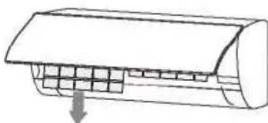
natural_image
Diagram of a car air conditioner unit with cooling fins and airflow direction arrow (no text or labels)-
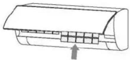
Use both hands to open the panel for an angle from both ends of the panel in accordance with the direction of the arrow.
-
Release the air filter from the slot and remove it.
■ Clean the Air Filter
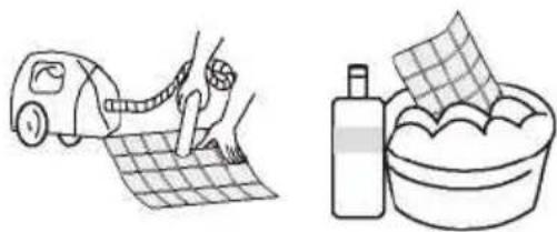
Use a vacuum cleaner or water to rinse filter, and if the filter is very dirty (for example, with greasy dirt), clean it with warm water (below 45 °C) with mild detergent dissolved in, and then put the filter in the shade to dry in the air
natural_image
Illustration of a person using a hairdryer to clean a grid-patterned surface next to a bowl filled with paper (no text or symbols)Clean and care
Mount the Filter
Reinstall the dried filter in reverse order of removal, then cover and lock the panel.
Mount the Filter
natural_image
Diagram of a car air conditioner unit with airflow direction indicated by an arrow (no text or labels)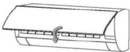
natural_image
Line drawing of a cylindrical air conditioner unit with a handle and internal slots (no text or symbols)Check before use
- Check whether all the air inlets and outlets of the units are unblocked.
- Check whether there is blocking in the water outlet of the drain pipe, and immediately clean it up if any.
- Check the ground wire is reliably grounded.
- Check whether the remote control batteries are installed, and whether the power is sufficient.
- Check whether there is damage in the mounting bracket of the outdoor unit, and if any, please contact our local service center.
Maintain after use
- Cut off the power source of the air conditioner, turn off the main power switch and remove the batteries from the remote controller.
- Clean the filter and the unit body.
-
Remove the dust and debris from the outdoor unit.
-
Check whether there is damage in the mounting bracket of the outdoor unit, and if any, please contact our local service center.
Troubleshooting
Caution
Do not repair the air conditioner by yourself as wrong maintenance may cause electric shock or fire or explode, please contact the authorized service center and let the professionals conduct the maintenance, and checking the following items prior to contacting for maintenance can save your time and money.
Phenomenon
The air conditioner does not work.
There might be power outages. ^^ Wait until power is restored
Power plug may be loose out from the socket.
- The plug in the plug tightly.
Power switch fuse may blow.^ Replace the fuse.
The time for timing boot is yet to come. -Wait or cancel the timer settings.
The air conditioner can't run after the immediate start-up after rit is shut down.
If the air conditioner is turned on immediately after it is turned off, the protective delay switch will delay the operation for 3 to 5 minutes
The air conditioner stops running after it starts up for a while
May reach the setting temperature.
— It is a normal function phenomenon.
May be at a defrosting state. — It will automatically restore and run again after defrosting.
Shutdown Timer may be set.
— If you continue to use, please turn it on again.
The indoor unit blows out odor.
The air conditioner itself does not have undesirable odor. If there is odor, it may be due to accumulation of the odor in the environment.
Clean the air filter or activate the cleaning function.
The wind blows out, but the cooling/heating effect is not good.
Excessive accumulation of dust on filter, blocking at air inlet and outlet, and the excessively small angle of the louver blades all will affect the cooling and heating effect.
— Please clean the filter, remove the obstacles at the air inlet and outlet and regulate the angle of the louver blades. Poor cooling and heating effect caused by doors and windows opening, and unclosed exhaust fan.
— Please close the doors, windows, the exhaust fan, etc. Auxiliary heating function is not turned on while heating, which may lead to poor heating effect.
— Turn on the auxiliary heating function. (only for models with auxiliary heating function) Mode setting is incorrect, and the temperature and wind speed settings are not appropriate.
— Please re-select the mode, and set the appropriate temperature and wind speed.
There is sound of running water during the running of air conditioner.
When the air conditioner is started up or stopped, or the compressor is started up or stopped during the running, sometimes the "hissing" sound of running water can be heard. — This is the sound of the flow of the refrigerant, not a malfunction.
A slight "click" sound is heard at the of start-up or shut-down.
Due to temperature changes, panel and other parts will swell, causing the sound of friction.
— This is normal, not a fault.
There are water drops over the surface of the indoor unit.
- When ambient humidity is high, water drops will be accumulated around the air outlet or the panel, etc. - This is a normal physics phenomenon.
- Prolonged cooling run in open space produces water drops. ^Close the doors and windows.
- Too small opening angle of the louver blades may also result in water drops at the air inlet. -Increase the angle of the louver blades.
The indoor unit makes abnormal sound.
- The sound of fan or compressor relay switched on or off.
- When the defrosting is started or stop running, it will sound.
That is due to the refrigerant flowed to reverse direction. They are not malfunctions.
- Too much dust accumulation in the air filter of the indoor unit may result in fluctuation of the sound.
Clean the air filters in time.
- Too much air noise when "Strong wind" is turned on.
-This is normal, if feeling uncomfortable, please deactivate the "Strong wind" function.
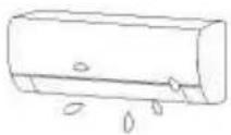
During the cooling operation, the indoor unit outlet sometimes will blow out mist
When the indoor temperature and humidity are high, it happens sometimes.
This is because the indoor air is cooled rapidly. After it runs for some time, the indoor temperature and humidity will be reduced and the mist will disappear.

Immediately stop all operations and cut off the power supply, contact our Service center locally in following situations.

Hear any harsh sound or smell any awful odor during running.

Abnormal heating of power cord and plug occurs.

The unit or remote controller has any Impurity or water.

Air switch or leakage protection switch is often disconnected.
AIR CONDITIONER
REMOTE CONTROLLER
specifications are subject to change without prior notice improvement. Consult with the sales agency or manufacturer
Thank you very much for purchasing our air conditioner. Please read this owner's manual carefully before using your air conditioner.
CONTENTS
Remote controller Specifications. 21
Operation buttons 22
Indicators on LCD 24
How to use the buttons 25
Auto operation....25
Cooling/Heating/Fan operation. 26
Dehumidifying operation 26
Adjusting air flow direction. 26
Timer operation. 27
Advanced functions....28
Handling the remote controller....30
European Disposal Guidelines....32
NOTE:
Buttons design is based on typical model and might be slightly different from the actual one you purchased the actual shape shall prevail.
All the functions described are accomplished by the unit. If the unit has no this feature, there is no corresponding operation happened when press the relative button on the remote controller.
When there are wide differences between “Remote controller Illustration” and “USER'S MANUAL” on function description, the description of “USER'S MANUAL” shall prevail.
Remote Controller Specifications
| Model | RG10B1(E)/BGEF |
| Rated Voltage | 3.0V(Dry batteries R03/LR03 2) |
| Signal Receiving Range | 8m |
| Environment | -5°C - 60 °C (23°F~140°F) |
Performance Feature
- Operating Mode: AUTO, COOL, DRY, HEAT and FAN.
- Timer Setting Function in 24 hours.
- Indoor Setting Temperature Range : 17°C\~30°C.
- Full function of LCD (Liquid Crystal Display).
NOTE:
- Buttons design might be slightly different from the actual one you
• purchased depending on individual models. - All the functions described are accomplished by the indoor unit.
- If the indoor unit has no this feature, there is no corresponding operation happened when press the relative button on the remote controller
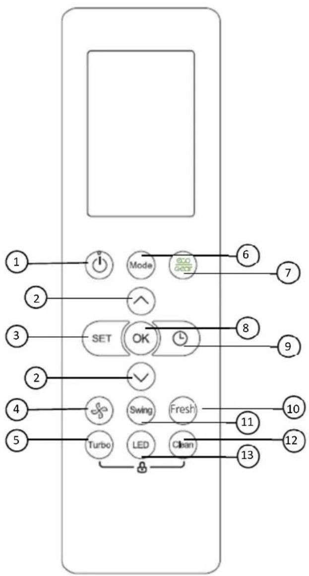
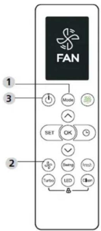
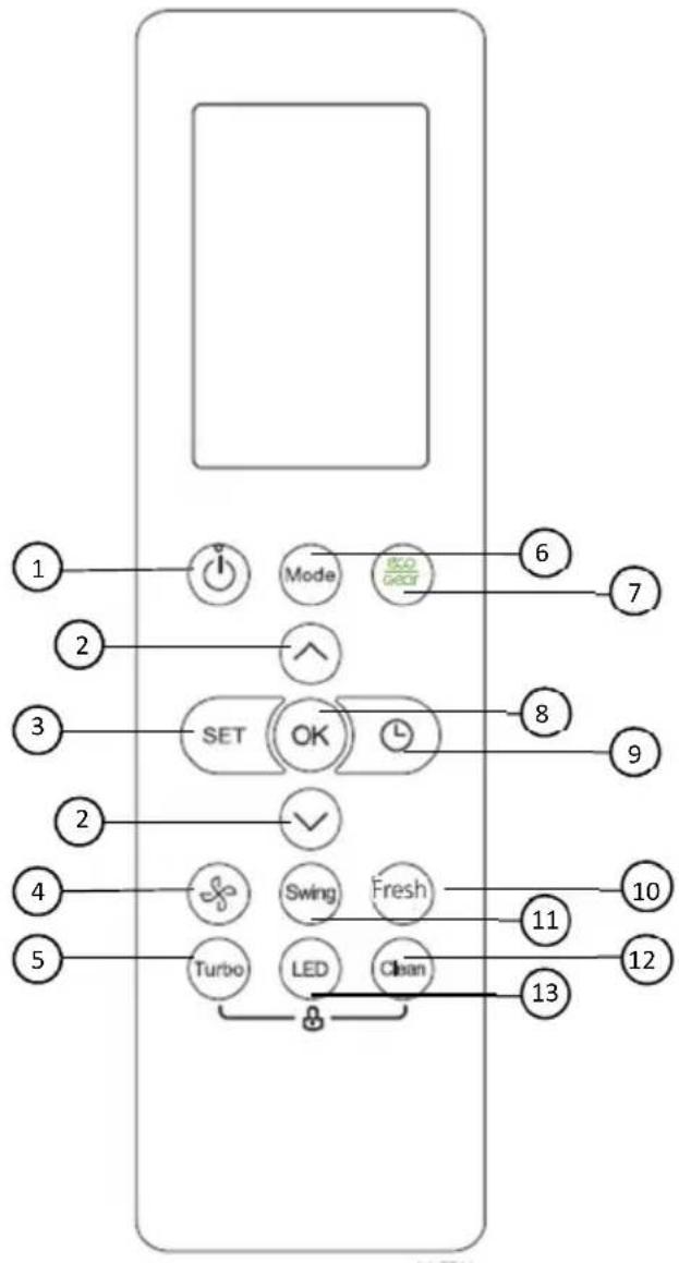
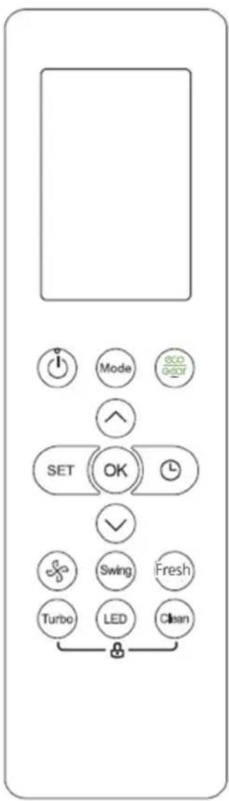
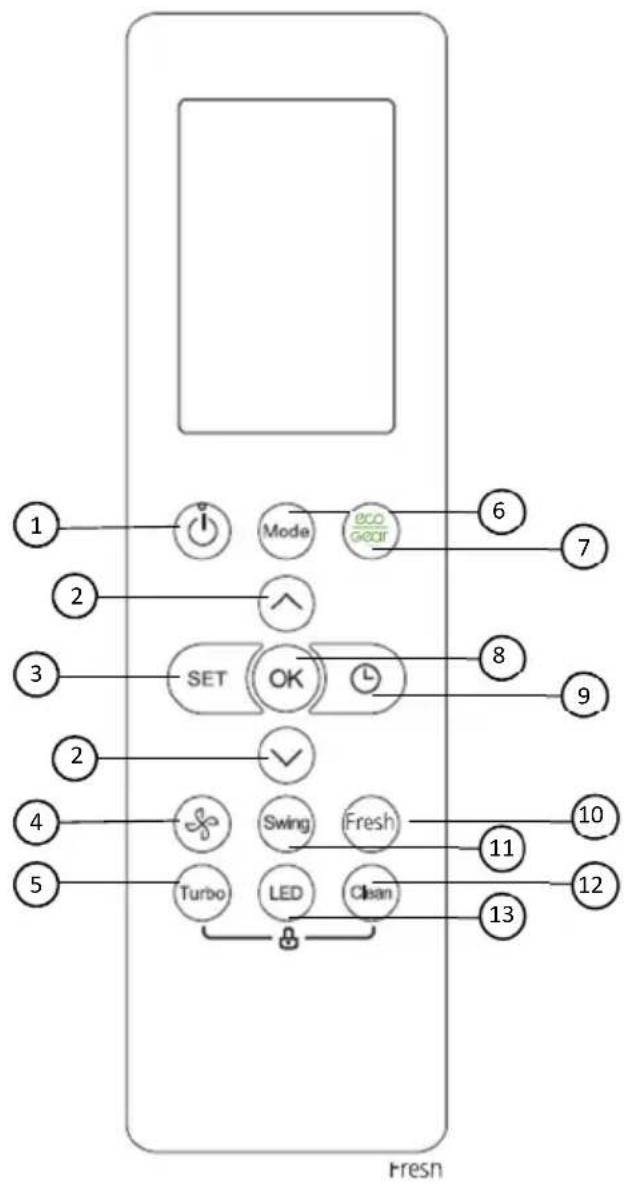
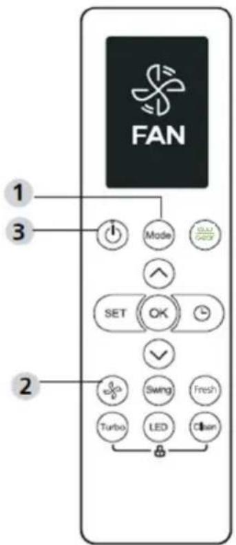
Function buttons
flowchart
graph TD
    A["1"] --> B["Mode"]
    B --> C["eco gear"]
    C --> D["6"]
    E["2"] --> F["SET"]
    F --> G["OK"]
    G --> H["8"]
    I["3"] --> J["SET"]
    J --> K["OK"]
    K --> L["9"]
    M["4"] --> N["Turbo"]
    N --> O["LED"]
    O --> P["Fresh"]
    Q["5"] --> R["Turbo"]
    R --> S["LED"]
    S --> T["Fresh"]
    U["6"] --> V["7"]
    W["8"] --> X["9"]
    Y["10"] --> Z["11"]
    AA["11"] --> AB["12"]
    AC["13"] --> AD["13"]
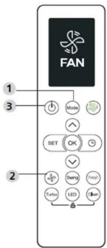
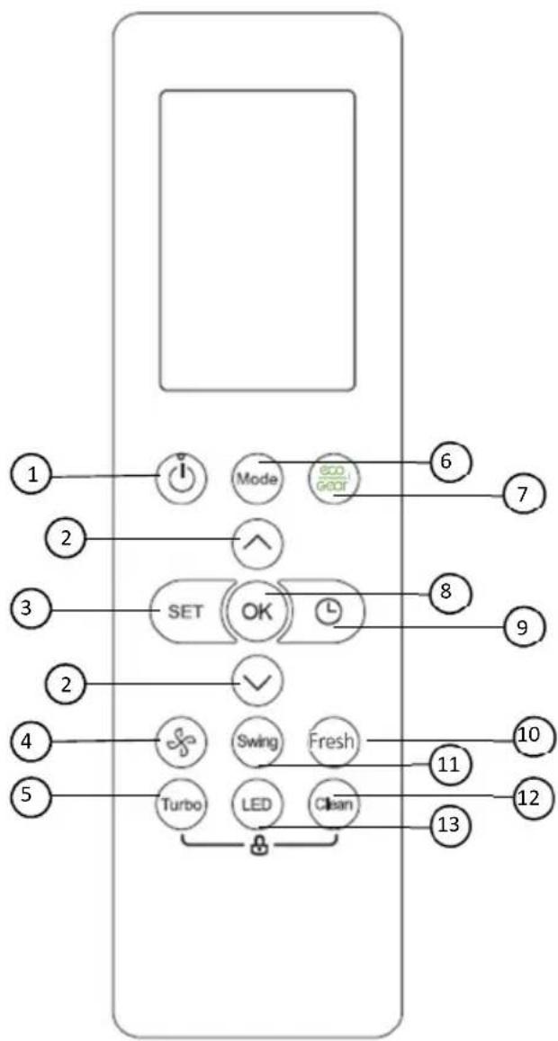
5. TURBO Button
1.ON/OFF Button
Operation starts when this button is pressed and stops when this button is pressed again.
2. TEMP ▲ / ▼ Button
Increases temperate in 1^ C increments. Max. temperature is 30^ C.
3. SET Button
Scrolls through operation functions as follows: Follow Me( ) → AP mode ( ) → FollowMe( ).
The selected symbol will flash on the display area, press OK button to confirm.
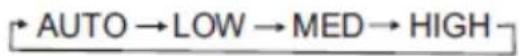
4.FAN SPEED
Selects fan speeds in the following order:
Enables unit to reach preset temperature in shortest possible time.
6. MODE Button
Each time the button is pressed, the operation mode is selected in a sequence of following:
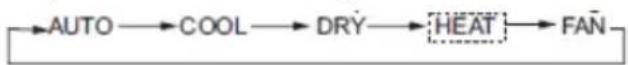
flowchart
graph LR
    A["AUTO"] --> B["COOL"]
    B --> C["DRY"]
    C --> D["HEAT"]
    D --> E["FAN"]
Note: HEAT mode is not supported appliance.
by the cooling only
flowchart
graph TD
    A["1"] --> B["Mode"]
    B --> C["6"]
    D["2"] --> E["SET"]
    E --> F["OK"]
    G["3"] --> H["OK"]
    I["4"] --> J["Turbo"]
    K["5"] --> L["LED"]
    M["6"] --> N["7"]
    O["8"] --> P["9"]
    Q["10"] --> R["11"]
    S["11"] --> T["12"]
    U["13"] --> V["13"]
7.ECO Button
enter the energy efficient mode
8.OK Button
Used to confirm the selected functions.
9. TIMER Button
Set timer to turn unit on or off.
10.FRESH Button
Used to start/stop the Fresh feature.
11.SWING Button
Starts and stops the horizontal louver movement.
12.CLEAN Button
Used to start/stop the Self Clean function.
13.LED Button
Turns indoor unit's LED display and air conditioner buzzer on and off (model dependent), which create a comfortable and quiet environment.
Indicator on LCD
Note:
All indicators shown in the figure are for the purpose of clear presentation. But during the actual operation only the relative functional signs are shown on the display window.
1. Features
From left to right:
- Fresh feature display
-
(No displays when Fresh feature is activated) Sleep mode display
-
ECO feature display
-
Wireless control feature display
-
Low battery detection display(If flashes)
2. Mode display
Displays the current operation mode.
Including AUTO
,
COOL *,
DRY ≡,
HEAT
FAN and again
AUTO.
3. ECO Display
Displays when ECO feature is activated
4. LOCK Display
Displays when LOCK feature is activated.
5. Transmission indicator /Timer On/ Off indicator
Transmission:
This transmission indicator lights when remote controller transmits signals to the indoor unit.
Timer On/Off:
This Timer indicator lights when Time ris turned on or off.
6. Temperature/Timer/Fan speed display
Displays the set temperature by default, or fan speed or timer setting when using TIMER ON/OFF functions.
Displays the temperature setting (17°C\~30°C). When you set the operating mode to FAN, no temperature setting is displayed. And if in the TIMER mode, shows the ON and OFF settings of the TIMER.
7. Fan speed display
Displays selected fan speed: Low/ Med/ High or Auto.
NOTE: This fan speed can not be adjusted in AUTO or DRY mode.
How to use the buttons?
Auto operation
Ensure the unit is plugged in and power is available. The OPERATION indicator on the display panel of the indoor unit starts flashing.
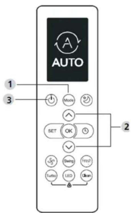
AUTO:
In AUTO mode, the unit will automatically select the COOL, FAN, or HEAT operation based on the set temperature.
-
Press the MODE button to select Auto.
-
Press the ▲/▼ button to set the desired temperature. The temperature can be set within a range of 17°C\~300°C in 10°C increments.
-
Press the ON/OFF button to start the air conditioner.
NOTE
-
In the Auto mode, the air conditioner can logically choose the mode of Cooling, Fan, and Heating by sensing the difference between the actual ambient room temperature and the setting temperature on the remote controller.
-
In the Auto mode, you can not switch the fan speed. It has already been automatically controlled.
-
If the Auto mode is not comfortable for you, the desired mode can be selected manually.
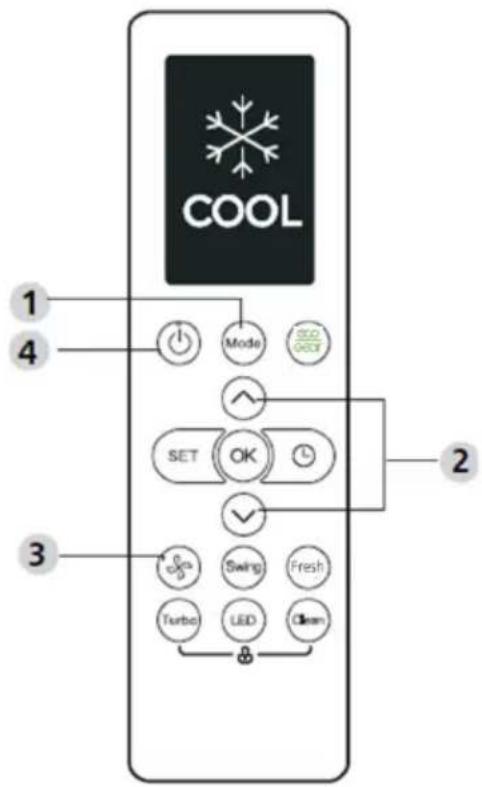
Cooling /Heating/Fan operation
- Press theMODE button to select COOL, HEAT (cooling & heating models only) or FAN mode.
- Press the UP/DOWN buttons to set the desired temperature. The temperature can be set within a range of 17°C\~30°C in 1°C increments.
- Press the FAN button to select the fan speed in four steps- Auto, Low, Mid, or High.
- Press the ON/OFF button to start the air conditioner.
NOTE
In the FAN mode, the setting temperature is not displayed in the remote controller and you are not able to control the room temperature either. In this case, only step 1, 3 and 4 may be performed.
Dehumidifying operation
- Press the MODE button to select DRY mode.
- Press the UP/DOWN buttons to set the desired temperature. The temperature can be set within a range of 17°C\~30°C in 1°C increments.
- Press the ON/OFF button to start the air conditioner.
NOTE
In the Dehumidifying mode, you can not switch the fan speed. It has already been automatically controlled.
Adjusting air flow direction (option)
- When push the SWING UP/DOWN button, the horizontal louver changes 6 degree in angle for each push. If pushing more than 2 seconds, the louver will automatically swing up and down.
Timer operation
Press the TIMER ON button can set the auto-on time of the unit. Press the TIMER OFF button can set the auto-off time of the unit.
To set the Timer-ON:
- Press the#IMER ON button.
- Press Temp. up or down button for multiple times to set the desired time to turn on the unit.
NOTE: If you want to set 2.5 h timer, you will press 5 times to set it (5 x 0,5 h).
- Point remote to unit and wait 1sec, the TIMER ON will be activated.
To set the Timer-OFF:
- Press TIMER button to initiate the OFF time sequence.
- Press Temp. up or down button for multiple times to set the desired time to turn off the unit.
NOTE: If you want to set timer off in 5 hours, you will press 10 times to set it (10 x 0,5 h).
- Point remote to unit and wait 1sec, the TIMER OFF will be activated.
NOTE:
- When setting the TIMER ON or TIMER OFF, the time will increase by 30 minutes increments with each press, up to 10 hours. After 10 hours and up to 24, it will increase in 1 hour increments. (For example, press 5 times to get 2.5h, and press 10 times to get 5h,) The timer will revert to 0.0 after 24.
- Cancel either function by setting its timer to 0.0h.
Example of timer setting
Example: If current timer is 1:00PM, to set the timer as above steps, the unit will turn on 2.5h later (3:30PM) and turn off at 6:00PM.
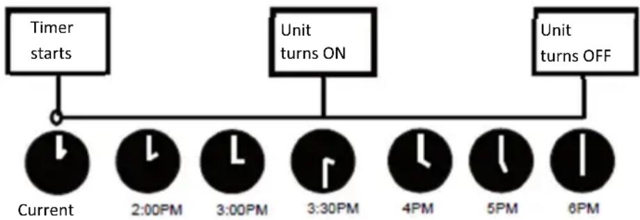
flowchart
graph TD
    A["Timer starts"] --> B["Current"]
    B --> C["2:00PM"]
    C --> D["3:00PM"]
    D --> E["3:30PM"]
    E --> F["4PM"]
    F --> G["5PM"]
    G --> H["6PM"]
    I["Unit turns ON"] --> E
    J["Unit turns OFF"] --> H
Time 1PM
ADVANCED FUNCTIONS
Swing Function
Press Swing button.
- The horizontal louver will swing up and down automatically when pressing Swing button. Press again to make it stop.
LED Display
Press LED button.
- Press this button to turn on and turn off the display on the indoor unit.
Silence Function
Keep pressing Fan button for more than 2 seconds to activate/disable Silence function.
Due to low frequency operation of compressor, it may result in insufficient cooling and heating capacity. Press ON/OFF, Mode, Sleep, Turbo or Clean button while operating will cancel silence function.
Lock Function
Press together Clean button and Turbo button at the same time more than 5 seconds to activate Lock function. All buttons will not response except pressing these two buttons for two seconds again to disable locking.
Clean Function
Press Clean button.
Airborne bacteria can grow in the moisture that condenses around heat exchanger in the unit. With regular use, most of this moisture is evaporated from the unit.
By pressing the CLEAN button, your unit will clean itself automatically. After cleaning, the unit will turn off automatically. Pressing the CLEAN button mid-cycle will cancel the operation and turn off the unit. You can use CLEAN as often as you like.
Note: You can only activate this function in COOL or DRY mode.
Turbo Function
Press TURBO Button.
- When you select Turbo feature in COOL/HEAT mode, the unit will blow cool air with strongest wind setting to jump-start the cooling/heating process.
SET Function
Press the SET button to enter the function setting, then press SET button or TEMP ▼ or TEMP ▲ button to select the desired function.
The selected symbol will flash on the display area, press the OK button to confirm.
To cancel the selected function, just perform the same procedures as above.
Press the SET button to scroll through operation functions as follows:
FRESH → SLEEP* → FOLLOW ME → AP mode
*: If your remote controller has Fresh and Sleep button, you can not use the SET button to select the Fresh and Sleep feature.
Fresh function

When the FRESH function is initiated, the ion generator is energized and will help to purify the air in the room.
Sleep function

The SLEEP function is used to decrease energy use while you sleep (and don't need the same temperature settings to stay comfortable).
AP function
Choose AP mode to do wireless network configuration. For some units, it doesn't work by pressing the SET button. To enter the AP mode, continuously press the LED button seven times in 10 seconds.
Follow me function

The FOLLOW ME function enables the remote control to measure the temperature at its current location and send this signal to the air conditioner every 3 minutes interval. When using AUTO, COOL or HEAT modes, measuring ambient temperature from the remote control (instead of from the indoor unit itself) will enable the air conditioner to optimize the temperature around you and ensure maximum comfort.
NOTE: Press and hold Turbo button for seven seconds to start/stop memory feature of Follow Me function.
Handling the remote controller
natural_image
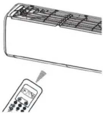
Line drawing of a car air conditioner unit with a handheld remote control (no text or symbols)Location of the remote controller.
Use the remote controller within a distance of 8 meters from the appliance, pointing it towards the receiver. Reception is confirmed by a beep.
CAUTIONS
- The air conditioner will not operate if curtains, doors or other materials block the signals from the remote controller to the indoor unit.
- Prevent any liquid from falling into the remote controller. Do not expose the remote controller to direct sunlight or heat.
- If the infrared signal receiver on the indoor unit is exposed to direct sunlight, the air conditioner may not function properly. Use curtains to prevent the sunlight from falling on the receiver.
- If other electrical appliances react to the remote controller, either move these appliances or consult your local dealer.
- Do not drop the remote controller. Handle with care. Do not place heavy objects on the remote controller, or step on it.
Replacing batteries
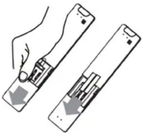
natural_image
Illustration of a hand holding a device with two views showing internal components (no text or symbols)The following cases signify exhausted batteries. Replace old batteries with new ones.
- Receiving beep is not emitted when a signal is transmitted.
- Indicator fades away.
The remote controller is powered by two dry batteries (R03/LR03X2) housed in the back rear part and protected by a cover.
(1) Remove the cover in the rear part of the remote controller.
(2) Remove the old batteries and insert the new batteries placing the (+) and (-) ends correctly.
(3) Install the cover back on.
NOTE: When the batteries are removed, the remote controller erases all programming. After inserting new batteries, the remote controller must be reprogrammed.

CAUTIONS
- Do not mix old and new batteries or batteries of different types.
- Do not leave the batteries in the remote controller if they are not going to be used for 2 or 3 months.
- Do not dispose batteries as unsorted municipal waste. Collection of such waste separately for special treatment is necessary.
p
The design and specifications are subject to change without prior notice for product improvement. Consult with the sales agency or manufacturer for details.
European Disposal Guidelines
To protect our environment and to recycle the raw materials used as completely as possible, the consumer is asked to return unserviceable equipment to the public collection system for electrical and electronic.
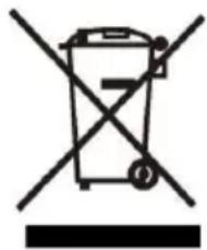
The symbol of the crossed indicates that this product must be returned to the collection point for electronic waste to feed it by recycling the best possible raw material recycling.
natural_image
Symbol of a trash bin crossed out by two crossed lines, no text or numbers presentBy ensuring this product you will prevent possible negative effects on the environment and human health, which could otherwise be caused due to improper disposal of that product. The recycling of materials from this product, you will help to preserve a healthy environment and natural resources.
For detailed information about the collection of EE products contact M SAN Grupa dd or the dealer where you purchased the product.
This appliance contains refrigerant and other potentially hazardous materials. When disposing of this appliance, the law requires special collection and treatment. Do not dispose of this product as household waste or unsorted municipal waste.
When disposing of this appliance, you have the following options:
- Dispose of the appliance at designated municipal electronic waste collection facility.
- When buying a new appliance, the retailer will take back the old appliance free of charge.
- The manufacturer will take back the old appliance free of charge.
- Sell the appliance to certified scrap metal dealers.
Special notice
Disposing of this appliance in the forest or other natural surroundings endangers your health and is bad for the environment. Hazardous substances may leak into the ground water and enter the food chain.
EU Declaraton of Conformity
This device is manufactured in accordance with the applicable European standards and in accordance with all applicable Directives and Regulations.
EU declaration of conformity can be downloaded from the following link: www.msan.hr/dokumentacijaartikala

POŠTOVANI!
Zahvaljujemo na kupnji VIVAX uređaja i nadamo se da ćete biti zadovoljni odabirom. Ako u jamstvenom roku bude potreban popravak proizvoda, molimo savjetujte se sa ovlaštenim prodavačem koji Vam je proizvod prodao ili nas kontaktirajte na dolje navedene brojeve i adrese. MOLIMO VAS DA PRIJE UPORABE PROIZVODA PAŽLJIVO PROČITATE UPUTE PRILOŽENE UZ PROIZVOD!
JAMSTVENI LIST HR
VIVAX
MODEL UREĐAJA
SERIJSKI BROJ
DATUM PRODAJE
BROJ RAČUNA PRODAVATELJA
POTPIS I PEČAT PRODAVATELJA
- Preuzimamo obavezu besplatno popraviti ili zamijeniti neispravne dijelove VIVAX klima uređaja koji bi se takvim pokazali za vrijeme trajanja jamstva, kao greška prilikom izrade ili montaže. Ovim jamstvom jamčimo da će predmet ovog jamstva raditi bez pogreške uzrokovane eventualnom lošom izradom ili lošim materijalom izrade. Svi, eventualno nastali, kvarovi biti će besplatno otklonjeni od strane ovlaštenog servisa u jamstvenom roku.
UVJETI JAMSTVA:
BROJ RAČUNA PRODAVAOCA
POTPIS I PEČAT PRODAVAOCA
- Preuzimamo obavezu da besplatno popravimo ili zamijenimo neispravne dijelove Vivax cool klima uređaja koji bi se takvim pokazali za vrijeme trajanja garancije, kao greška prilikom izrade ili montaže
Ovom garancijom garantujemo da će predmet ove garancije raditi bez pogreške uzrokovane eventualnom lošom izradom ili lošim materijalom izrade. Svi, eventualno nastali, kvarovi biće besplatno otklonjeni u ovlaštenom servisu u garantnom roku.
USLOVI GARANCIJE:
-
Garancija na Vivax cool klima uređaje počinje teći od dana kupovine proizvoda i traje 24 mjeseca, osim modela ACP-xxxxCCxxxxx, ACP-xxxxCTxxxxx, ACP-xxxxDTxxxxx, ACP-xxxxCFxxxxx, ACP-xxxxFSxxxxx za koje vrijedi garancija u trajanju od 12 mjeseci
-
Garancija na uređaje u upotrebi produžuje se za sljedećih 12 mjeseci nakon izvršenja garantnog servisnog pregleda od strane ovlaštenog servisa.
-
Garancija se može produžavali ukupno tri puta, osim modela ACP-xxxxCCxxxxx, ACP-xxxxCTxxxxx, ACP-xxxxDTxxxxx, ACP-xxxxCFxxxxx, ACP-xxxxFSxxxxx za koje se garancija može produljivati četiri puta, što u ukupnom trajanju može iznositi maksimalno 60 mjeseci
-
Garantni servisni pregled naplaćuje ovlašteni servis po cjenovniku zastupnika KimTec d.o.o. i/ili Kim Tec servis d.o.o. i ovjerava garantni list što dokazuje produženje i valjanost garancije
-
Garancija vrijedi ako su montaža ili servis Vivax cool klima uređaja obavljeni od strane ovlaštenog servisa kojeg je ovlastio zastupnik Kimtec d.o.o..
-
Vivax cool klima uređaj kao cjelinu čine unutarnja jedinica, instalacija i vanjska jedinica koji su pravilno odabrani i koji međusobno odgovaraju po modelu i snazi.
-
U slučaju kvara na Vivax cool klima uređaju obvezujemo se da ćemo isti popraviti u najkraćem mogućem roku, a najkasnije u roku 45 dana, ako se Vivax cool klima uređaj ne može popraviti ili se ne popravi u roku od 45 dana, biće zamijenjen novim. Ako popravak Vivax cool klima uređaja traje duže od 10 dana, garancija će sa produžiti za vrijeme trajanja popravka.
-
Garancija se priznaje samo uz račun o kupovini, te uz ovaj garantni list koji mora bili ispravno popunjen i ovjeren od strane prodavca, ovlaštenog montažera ili servisera.
-
Davaoc garancije osigurava servis i rezervne dijelova 7 godina od datuma kupnje Vivax cool klima uređaj
11. GARANCIJA NE OBUHVATA:
Redovnu provjeru, održavanje uz zamjenu dijelova koji se troše normalnom upotrebom, prilagođavanje ili promjene za poboljšanje proizvoda za primjenu koji nisu opisane u tehničkim uputstvima za korištenje, osim ako je za te preinake predočena saglasnost M SAN GRUPA d.o.o.; i KimTec d.o.o. i/ili Kim Tec servis d.o.o.
12. Garancija se ne priznaje u sljedećim slučajevima:
Ako kupac ne predoči ispravan garantni list i račun o kupovini.
POTPIS I PEČAT PRODAVCA
- Ovom izjavom o saobraznosti proizvođač proizvoda, preko KIM TEC CG d.o.o., kao uvoznika i davaoca prava u Crnoj Gori osigurava besplatan popravak istog u skladu s vazečim propisima i u skladu s uslovima opisanim u ovoj izjavi o saobraznosti.
- Ovom izjavom o saobraznosti ističemo da će predmet ovog prava raditi bez greške uzrokovane eventualnom lošom Izradom i lošim materijalom izrade. Svi eventualno nastali kvarovi biće besplatno otklonjeni u ovlašcenom servisu u predvidjenom roku za reklamaciju.
- Rok za reklamaciju proizvoda počinje od dana kupovine proizvoda i traje 24 mjeseca.
- Rok za reklamaciju proizvoda u upotrebi produžuje se za sljedećih 12 mjeseci nakon izvršenja kontrolnog servisnog pregleda od strane ovlašćenog servisa.
- Rok za reklamaciju proizvoda može se produžavati ukupno tri puta, što u ukupnom trajanju može iznositi maksimalno 60 mjeseci
- U slučaju kvara na proizvodu koji je predmet reklamacije, obavezujemo se da ćemo isti popraviti u najkraćem mogućem roku, a najkasnije u roku od 15 dana. Ako se proizvod ne može popraviti ili se ne popravi u roku od 15 dana, biće zamijenjen novim.
- Pravo na reklamaciju se priznaje uz fiskalni račun o kupovini, ili uz ovu izjavu o saobraznosti koji mora biti ispravno popunjen odnosno mora sadržati datum prodaje, pečat i potpis prodavca.
- Davalac izjave o saobraznosti osigurava servis i rezervne djelove u razumno m vremenskom periodu.
PRAVO NA REKLAMACIJU NE OBUHVATA
City Company Adress Phone
| Prishtine-Fush Kosove-Lipjan | Eko Electronics | Vëllezërit Fazliu Nr. 74 | 045553800 |
| Prishtine-Fush Kosove-Lipjan | Unique | Rr.Isa Kastrati p.n Kompleksi ARKOS | 049111499 |
| Ferizaj Termo Ylli | 044677077 | ||
| Gjilan-Viti | Toni-Impex | 28 Nentori nr 60 | 044 490 939 |
| Mitrovice Kulla | Ahmet Maloku 60 | 049307307 | |
| Peje | Uraniku | Vitomerice | 049178749 |
| Peje | CTA | Sahit Bakalli nr. 24 | 049506447 |
| Gjakove | Lila Tech | Rr. Skenderbeu | 048116811 |
| Prizren-Suharek-Malisheve | Perfect Service | Lidhja e dukagjinit | 048166141 |
| Prizren-Suharek-Malisheve | Miranda- X-Tronics | Prizren | 044140434 |
| Kosove | Xhela Gorenje | Drenas | 048170700 |
sSPOŠTOVANI KUPCI!
Zahvaljujemo se vam za nakup Vivax klimatske naprave. Upamo, da boste z izbiro zadovoljni.
PROSIMO, DA PRED UPORABO PROIZVODA NATANČNO PREBERETE TEHNIČNO DOKUMENTACIJO TER PRILOŽENA NAVODILA ZA UPORABO