
Narvik 35 - Heat pump WILFA - Free user manual and instructions
Find the device manual for free Narvik 35 WILFA in PDF.


| Brand | Wilfa |
| Model | Narvik 35 |
| Product Type | Air-to-Air Heat Pump |
| Dimensions (W x H x D) | 800 x 300 x 200 mm |
| Weight | 20 kg |
| Power Supply | 230 V / 50 Hz |
| Heating Capacity | 3.5 kW |
| Cooling Capacity | 3.2 kW |
| Energy Efficiency (EER / COP) | 3.5 / 4.0 |
| Refrigerant | R32 |
| Sound Level (Indoor / Outdoor) | 45 dB(A) / 55 dB(A) |
| Main Functions | Heating, Cooling, Dehumidification, Fan, Timer, Remote Control |
| Maintenance | Clean filters every 2 weeks; professional service annually |
| Safety Features | Overheat Protection, Auto Restart, Child Lock |
| Spare Parts Available | Filters, Remote Control, Fan Motor, PCB |
| Repairability Index | 7.5 / 10 |
| Optional Accessories | Wi-Fi Module, Wall Mounting Kit |
| Warranty | 2 years |
Frequently Asked Questions - Narvik 35 WILFA
User questions about Narvik 35 WILFA
0 question about this device. Answer the ones you know or ask your own.
Ask a new question about this device
Download the instructions for your Heat pump in PDF format for free! Find your manual Narvik 35 - WILFA and take your electronic device back in hand. On this page are published all the documents necessary for the use of your device. Narvik 35 by WILFA.
USER MANUAL Narvik 35 WILFA
natural_image
Front view of a white air conditioner unit with ventilation grille and 'wifa' logo (no text or symbols on body)NARVIK 25 and 35
HEAT PUMP
EN . Instruction manual
25 CLEANING AND MAINTENANCE
27 TROUBLESHOOTING
30 ERROR CODE
32 GUARANTEE
33 PRODUCT SPECIFICATIONS
33 SUPPORT AND SPARE PARTS
33 RECYCLABILITY
IMPORTANT SAFETY INSTRUCTIONS – OPERATION AND MAINTENANCE
- Read this instruction manual thoroughly before use and save it for future reference. It is also available at our website; wilfa.com.
- This appliance can be used by children aged from 8 years and above and persons with reduced physical, sensory or mental capabilities or lack of experience and knowledge if they have been given supervision or instruction concerning use of the appliance in a safe way and understand the hazards involved.
• Children shall not play with the appliance. - Cleaning and user maintenance shall not be made by children without supervision.
- Do not connect air conditioner to multi-purpose socket. Otherwise, it may cause fire hazard.
- Do disconnect power supply when cleaning air conditioner. Otherwise, it may cause electric shock.
- If the supply cord is damaged, it must be replaced by the manufacturer, its service agent or similarly qualified persons in order to avoid a hazard.
- Do not wash the air conditioner with water to avoid electric shock.
- Do not spray water on indoor unit. It may cause electric shock or malfunction.
- After removing the filter, do not touch fins to avoid injury. Do not use fire or hair dryer to dry the filter to avoid deformation or fire hazard.
- Maintenance must be performed by qualified professionals. Otherwise, it may cause personal injury or damage.
- Do not repair air conditioner by yourself. It may cause electric shock or damage. Please contact dealer when you need to repair air conditioner.
- Do not extend fingers or objects into air inlet or air outlet. It may cause personal injury or damage.
- Do not block air outlet or air inlet. It may cause malfunction.
- Do not spill water on the remote controller, otherwise the remote controller may be broken.
- When below phenomenon occurs, please turn off air conditioner and disconnect power immediately, and then contact the dealer or qualified professionals for service.
– Power cord is overheating or damaged.
– There's abnormal sound during operation.
– Circuit break trips off frequently.
EN
– Air conditioner gives off burning smell.
- Indoor unit is leaking.
- If the air conditioner operates under abnormal conditions, it may cause malfunction, electric shock or fire hazard.
- When turning on or turning off the unit by emergency operation switch, please press this switch with an insulating object other than metal.
- Do not step on top panel of outdoor unit, or put heavy objects. It may cause damage or personal injury.
IMPORTANT SAFETY INSTRUCTIONS – ATTACHMENT
- Installation must be performed by qualified professionals. Otherwise, it may cause personal injury or damage.
- Must follow the electric safety regulations when installing the unit.
- According to the local safety regulations, use qualified power supply circuit and circuit break.
-
Do install the circuit break. If not, it may cause malfunction. An all-pole disconnection switch having a contact separation of at least 3mm in all poles should be connected in fixed wiring.
-
Including an circuit break with suitable capacity, please note the following table. Air switch should be included magnet buckle and heating buckle function, it can protect the circuit-short and overload.
• Air Conditioner should be properly grounded. Incorrect grounding may cause electric shock. - Don't use unqualified power cord.
- Make sure the power supply matches with the requirement of air conditioner. Unstable power supply or incorrect wiring or malfunction.
- Please install proper power supply cables before using the air conditioner.
- Properly connect the live wire, neutral wire and grounding wire of power socket.
- Be sure to cut off the power supply before proceeding any work related to electricity and safety.
- Do not put through the power before finishing installation. If the supply cord is damaged, it must be replaced by the manufacturer, its service agent or similarly qualified persons in order to avoid a hazard.
EN
- The temperature of refrigerant circuit will be high, please keep the interconnection cable away from the copper tube.
- The appliance shall be installed in accordance with national wiring regulations.
- Installation must be performed in accordance with the requirement of NEC and CEC by authorized personnel only.
- The air conditioner is the first class electric appliance. It must be properly grounding with specialized grounding device by a professional. Please make sure it is always grounded effectively, otherwise it may cause electric shock.
- The yellow-green wire in air conditioner is grounding wire, which can't be used for other purposes.
- The grounding resistance should comply with national electric safety regulations.
- The appliance must be positioned so that the plug is accessible.
- All wires of indoor unit and outdoor unit should be connected by a professional.
-
If the length of power connection wire is insufficient, please contact the supplier for a new one. Avoid extending the wire by yourself.
-
For the air conditioner with plug, the plug should be reachable after finishing installation.
- For the air conditioner without plug, an circuit break must be installed in the line.
- If you need to relocate the air conditioner to another place, only the qualified person can perform the work. Otherwise, it may cause personal injury or damage.
- Select a location which is out of reach for children and far away from animals or plants. If it is unavoidable, please add the fence for safety purpose.
- The indoor unit should be installed close to the wall
NOTE
It is very important for your customer rights, that you follow your cleaning and service advizing thoroughly. If not, you will risk to lose your customer rights.
THE REFRIGERANT
- To realize the function of the air conditioner unit, a special refrigerant circulates in the system. The used refrigerant is the fluoride R32, which is specially cleaned. The refrigerant is flammable and inodorous. Furthermore, it can lead to explosion under certain conditions. But the flammability of
the refrigerant is very low. It can be ignited only by fire.
- Compared to common refrigerants, R32 is a nonpolluting refrigerant with no harm to the ozonosphere. The influence upon the greenhouse effect is also lower. R32 has got very good thermodynamic features which lead to a really high energy efficiency. The units therefore need a less filling.
WARNING
Do not use means to accelerate the defrosting process or to clean, other than those recommended by the manufacture. Should repair be necessary, contact your nearest authorized Service Centre. Any repairs carried out by unqualified personnel may be dangerous. The appliance shall be stored in a room without continuously operating ignition sources. (for example: open flames, an operating gas appliance or an operating electric heater.) Do not pierce or burn.
Appliance filled with flammable gas R32. For repairs, strictly follow manufacturer's instructions only. Be aware that refrigrants not contain odour. Read specialist's manual.

natural_image
Four black-and-white icons: warning triangle with flame, open book, open book with 'i' symbol, and open book with wrench (no text or labels)PRECAUTIONS
- Do not put through the power before finishing installation.
- If the supply cord is damaged, it must be replaced by the manufacturer, its service agent or similarly qualified persons in order to avoid a hazard.
- The temperature of refrigerant circuit will be high, please keep the interconnection cable away from the copper tube.
- The appliance shall be installed in accordance with national wiring regulations.
- Installation must be performed in accordance with the requirement of NEC and CEC by authorized personnel only.
- The air conditioner is the first class electric appliance. It must be properly grounding with specialized grounding device by a professional. Please make sure it is always grounded effectively, otherwise it may cause electric shock.
- The yellow-green wire in air conditioner is grounding wire, which can't be used for other purposes.
- The grounding resistance should comply with national electric safety regulations.
EN
- The appliance must be positioned so that the plug is accessible.
- All wires of indoor unit and outdoor unit should be connected by a professional.
- If the length of power connection wire is insufficient, please contact the supplier for a new one. Avoid extending the wire by yourself.
- For the air conditioner with plug, the plug should be reachable after finishing installation.
- For the air conditioner without plug, an circuit break must be installed in the line.
- If you need to relocate the air conditioner to another place, only the qualified person can perform the work. Otherwise, it may cause personal injury or damage.
- Select a location which is out of reach for children and far away from animals or plants. If it is unavoidable, please add the fence for safety purpose.
- The indoor unit should be installed close to the wall.
- Instructions for installation and use of this product are provided by the manufacturer.
WORKING TEMPERATURE RANGE
NARVIK 25
Indoor side DB/WB(°C) Outdoor side DB/WB(°C)
Maximum cooling 32/23 43/26
Maximum heating 27/- 24/18
Note: The operating temperature range (outdoor temperature) for cooling is -15^ 43^ ; Heating temperature range for the model without electric heating belt for chassis is -15^ 24^ . Heating temperature range for the model with electric heating belt for chassis is -25^ 24^ .
NARVIK 35
Indoor side DB/WB(°C) Outdoor side DB/WB(°C)
Maximum cooling 32/23 52/32
Maximum heating 27/- 24/18
Note: The operating temperature range (outdoor temperature) for cooling only unit is -18^ 52^ ; for heat pump unit is -30^ 52^ .
PRODUCT OVERVIEW
INDOOR UNIT
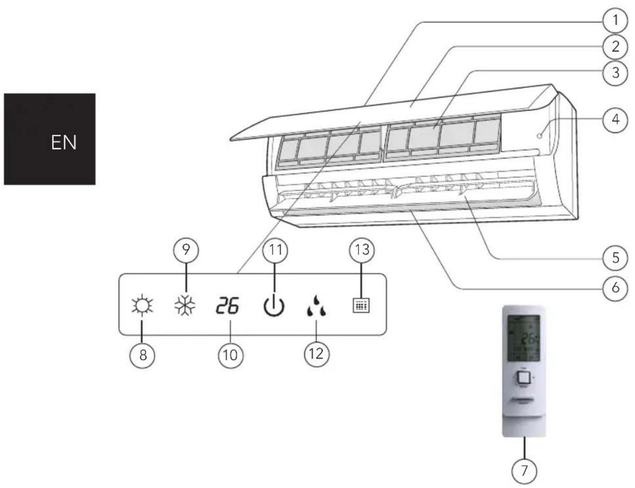
- Air inlet
- Panel
- Filter
- Aux. button
- Horizontal louver
- Air outlet
- Remote control
Display:
- Heating indicator
- Cooling indicator
- Temperature indicator
- Power indicator
- Drying indicator
- Reciver window
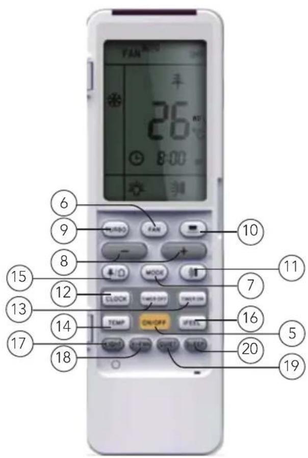
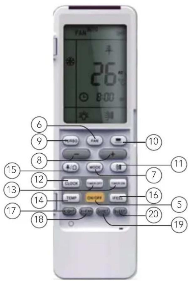
REMOTE CONTROL
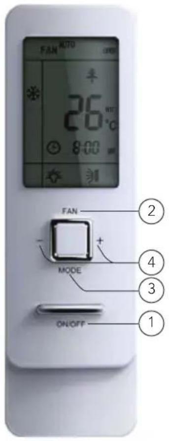

- ON/OFF button
- FAN button
- MODE button
- +/- button
- ON/OFF button
- FAN button
- MODE button
- +/- button
- TURBO button
- button
-
button
-
CLOCK button
- TIMER ON / TIMER OFF button
- TEMP button
- / button
- I FEEL button
- LIGHT button
- WIFI button
19 QUIET button
20 SLEEP button
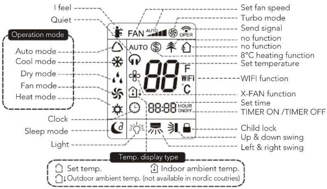
DISPLAY SCREEN
HOW TO USE
INTRODUCTION FOR BUTTONS ON REMOTE CONTROLLER
Note:
- This is a general use remote controller, it could be used for the air conditioners with multifunction; For some function, which the model don't have, if press the corresponding button on the remote controller that the unit will keep the original running status.
• After putting through the power, the air conditioner will give out a sound. - Operation indicator "Is ON (red indicator). After that, you can operate the air conditioner by using remote controller.
- Under on status, pressing the button on the remote controller, the signal icon "on the display of remote controller will blink once and the air conditioner will give out a "de" sound, which means the signal has been sent to the air conditioner.
- Under off status, set temperature and clock icon will be displayed on the display of remote controller (If timer on, timer off and light functions are set, the corresponding icons will be displayed on the display of remote controller at the same time); Under on status, the display will show the corresponding set function icons.
①/⑤ ON/OFF button
Press this button, the unit will be turned on, press it once more, the unit will be turned off. Sleep function will be canceled, while unit off.
②/⑥ FAN button
Press this button, Auto, Low, Medium-low, Medium, Medium-high, High speed can be circularly selected. After powered on, Auto fan speed is default. Under DRY mode, Low fan speed only can be set up.

flowchart
graph LR
    A["AUTO"] --> B["Low Fan"]
    B --> C["Medium Fan"]
    C --> D["Medium-high Fan"]
    D --> E["High Fan"]
Note: It's Low fan speed under Dry mode.
③/⑦ MODE button
Press this button, Auto, Cool, Dry, Fan, Heat mode can be selected circularly. Auto mode is default while power on. Under Auto mode, the temperature will not be dis-played; Under Heat mode, the initial value is 28^ C; Under other modes, the initial value is 25^ C.
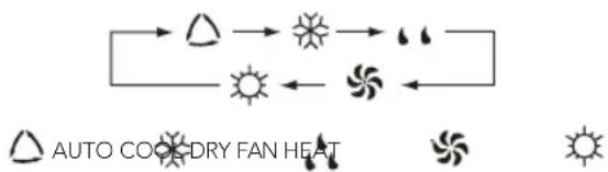
flowchart
graph TD
    A["Start"] --> B["Sun"]
    B --> C[" blades"]
    C --> D[" blades"]
    D --> E["Back to Sun"]
    E --> F["End"]
④/⑧ +/- button
Presetting temperature can be increased. Press this button, the temperature can be set up, continuously press this button and hold for two seconds, the relative contents can quickly change, until unhold this button and send the order that the °C signal will be displayed all the time. The temperature adjustment is unavailable under the Auto mode, but the order can be sent if pressing this button. Temperature of degree setting: 16-30°C.
Presetting temperature can be decreased. Press this button, the temperature can be set up, continuously press this button and hold for two seconds, the relative contents can quickly change, until unhold this button and send the order that the °C signal will be displayed all the time. The temperature adjustment is unavailable under the Auto mode, but the order can be sent by if pressing this button.
⑨ TURBO button
Under Cool or Heat mode, press this button can turn on or turn off the Turbo function. After the Turbo function turned on, the signal of Turbo will display. The signal will be automatically cancelled if changing the mode or fan speed.
⑩ button
Press this button to set left & right swing angle cycling as below:
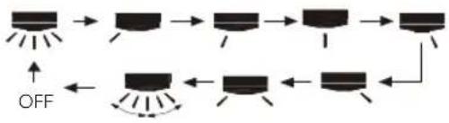
flowchart
graph TD
    A["Start"] --> B["Step 1"]
    B --> C["Step 2"]
    C --> D["Step 3"]
    D --> E["Step 4"]
    E --> F["OFF"]
    F --> G["Step 5"]
    G --> H["Step 6"]
    H --> I["Step 7"]
    I --> J["Step 8"]
⑪ button
Press this button to set swing angle, which circularly changes as below:
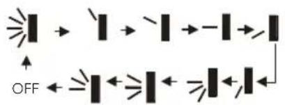
flowchart
graph TD
    A["ON"] --> B["X"]
    B --> C["X"]
    C --> D["I"]
    D --> E["-"]
    E --> F["X"]
    F --> G["O"]
    G --> H["OFF"]
This remote controller is universal. If it receives threes kinds of following status, the swing angle will remain original.
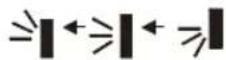
If guide louver is stopped when it is swinging up and down, it will remian its present position.
indicates guide louver swings back and forth in the five places, as shown in the figure.
⑫ CLOCK button
Press this button, the clock can be set up, signal blink and display. Within 5 seconds, the value can be adjusted by pressing + or - button, if continuously press this button for 2 seconds above, in every 0.5 seconds, the value on ten place of Minute will be increased 1. During blinking, repress the Clock button or Confirm button, signal will be constantly displayed and it denotes the setting succeeded. After powered on, 12:00 is defaulted to display and signal will be displayed. If there is signal be displayed that denotes the current time value is Clock value, otherwise is Timer value.
⑬ TIMER ON/TIMER OFF button
Timer On setting: Signal "ON" will blink and display, signal will conceal, the numerical section will become the timer on setting status. During 5 seconds blink, by pressing + or - button to adjust the time value of numerical section, every press of that button, the value will be increased or decreased 1 minute. Hold pressing + or - button, 2 seconds later, it quickly change, the way of change is: During 5s blink, press the Timer button, the timer setting succeeds. The Timer On has been set up, repress the timer button, the Timer On will be canceled. Before setting the Timer, please adjust the Clock to the current actual time.
One press this key to enter into TIMER OFF setup, in which case the TIMER OFF icon will blink. The method of setting is the same as for TIMER ON.
⑭ TEMP button
Press this button, you can see indoor set temperature, indoor ambient temperature or outdoor ambient temperature on indoor unit's display. The setting on remote controller is selected circularly as below:
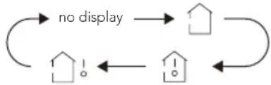
flowchart
graph TD
    A["no display"] --> B["House"]
    B --> C["House"]
    C --> D["House"]
    D --> E["House"]
    E --> A
When selecting “with remote controller or no display, temperature indicator on in-door unit displays set temperature; When selecting “with remote controller, temperature indicator on indoor unit displays indoor ambient temperature; When selecting “with remote controller, temperature indicator on indoor unit displays outdoor ambient temperature. 3s later it will return to the setting temperature or it depends on the other received signal within 3 seconds.
Attention: When displaying the outdoor ambient, the displaying range is 0-60°C. When it goes beyond the range, it keeps the threshold data (the smallest 0°C and the largest 60°C).
Tip: When operating buttons on the cover please make sure the cover is closed completely
Note: Outdoor temperature display is not available for some models. At that time, indoor unit receives "signal", while it displays indoor set temperature.
⑮ This function is not applicable for Nordic models.
⑯ I FEEL button
Press this button once, to turn on the I FEEL function, then the figure of "I FEEL" will be displayed, after every press of other function button, every 200ms to send I FEEL once, after this function started, the remote controller will send temperature to the main unit in every 10 minutes. When repress this button, this function will be turned off. When I FEEL function is turned on, the remote controller should be put within the area where indoor unit can receive the signal sent by the remote controller.
⑰ LIGHT button
Press this button at unit On or Off status, Light On and Light Off can be set up. After powered on, Light On is defaulted.
⑱ WIFI button
Press WIFI button to activate function. Press again to stop function. More information about WIFI function from operation manual or wilfa.no, wilfa.com
⑲ QUIET button
Press this button, the Quiet status is under the Auto Quiet mode (display "") and "Auto" signal) and Quiet mode (display "")singal) and Quiet OFF (there is no signal of "")displayed), after powered on, the Quiet OFF is defaulted. Under the Quiet mode (Display "")signal). The Quiet function is only available for some models.
⑳ SLEEP button
Press this button, can select Sleep 1 (Sleep 2), Sleep 3 and cancel the Sleep, circulate between these, after electrified, Sleep Cancel is defaulted.
Sleep 1 is Sleep mode 1, in Cool, Dehumidify modes: sleep status after run for one hour, the main unit setting temperature will increase 1^ C, 2 hours, setting temperature increased 2^ C, the unit will run at this setting temperature; In Heat mode: sleep status after run for one hour, the setting temperature will decrease 1^ C, 2 hours, setting temperature will decrease 2^ C, then the unit will run at this setting temperature.
Sleep 2 is sleep mode 2, that is air conditioner will run according to the presetting a group of sleep temperature curve. In Cool mode:
- When setting the initial temperature 16^ C- 23^ C, after turned on Sleep function, the temperature will be increased 1^ C in every hour, after 3^ C the temperature will be maintained, after 7 hours, the temperature will be decreased 1^ C, after that the unit will keep on running under this temperature;
- When setting the initial temperature 24^ C- 27^ C, after turned on Sleep function, the temperature will be increased 1^ C in every hour, after 2^ C the temperature will be maintained, after 7 hours, the temperature will be decreased 1^ C, after that the unit will keep on running under this temperature;
- When setting the initial temperature 28^ C- 29^ C, after turned on Sleep function, the temperature will be increased 1^ C in every hour, after 1^ C the temperature will be maintained, after 7 hours, the temperature will be decreased 1^ C, after that the unit will keep on running under this temperature;
- When setting the initial temperature 30^ C, under this temperature setting, after 7 hours, the temperature will be decreased 1^ C, after that the unit will keep on running under this temperature;
In Heat mode:
- Under the initial presetting temperature 16^ C, it will run under this setting temperature all along.
- Under the initial presetting temperature 17^ C - 20^ C , after Sleep function started up, the temperature will decrease 1^ C in every hour, after 1^ C decreased, this temperature will be maintained.
-
Under the initial presetting temperature 21^ C- 27^ C, after Sleep function started up, the temperature will decrease 1^ C in every hour, after 2^ C decreased, this temperature will be maintained.
-
Under the initial presetting temperature 28^ C- 30^ C, after Sleep function started up, the temperature will decrease 1^ C in every hour, after 3^ C decreased, this temperature will be maintained.
Sleep 3 - the sleep curve setting under Sleep mode by DIY:
- Under Sleep 3 mode, press "Turbo" button for a long time, remote controller en-ters into user individuation sleep setting status, at this time, the time of remote controller will display "1hour", the setting temperature "88" will display the corr-esponding temperature of last setting sleep curve and blink (the first entering will display according to the initial curve setting value of original factory);
- Adjust "+" and "-" button, could change the corresponding setting temperature, after adjusted, press "Turbo" button for confirmation;
- At this time, 1 hour will be automatically increased at the timer position on the remote controller, (that are "2 hours" or "3 hours" or "8 hours"), the place of se-tting temperature "88" will display the corresponding temperature of last setting sleep curve and blink;
- Repeat the above step (2)\~(3) operation, until 8 hours temperature setting finished, sleep curve setting finished, at this time, the remote controller will resume the original timer display; temperature display will resume to original setting temperature.
Sleep 3 - the sleep curve setting under Sleep mode by DIY could be inquired: The user could accord to sleep curve setting method to inquire the presetting sleep curve, enter into user individuation sleep setting status, but do not change the temperature, press "Turbo" button directly for confirmation.
Note: In the above presetting or enquiry procedure, if continuously within 10s, there is no button pressed, the sleep curve setting status will be automatically quit and resume to display the original displaying. In the presetting or enquiry procedure, press "ON/OFF" button, "Mode" button, "Timer" button or "Sleep" button, the sleep curve setting or enquiry status will quit similarly.
Combination of "TEMP" and "CLOCK" buttons:
About Energy - saving Function
Press "TEMP" and "CLOCK" simultaneously in COOL mode to start energy-saving function. Nixie tube on the remote controller displays "SE". Repeat the operation to quit the function.
Combination of "TEMP" and "CLOCK" buttons:
About 8°C Heating Function
Press "TEMP" and "CLOCK" simultaneously in HEAT mode to start 8°C heating function. Nixie tube on the remote controller displays "⑧and a selected temperature of "8°C". Repeat the operation to quit the function.
CHILDLOCK FUNCTION
Press "▲" and "▼" simultaneously to turn on or turn off child lock function. When child lock function is on, "icon is displayed on remote controller. If you operate the remote controller, the "icon will blink three times without sending signal to the unit.
TEMPERATURE DISPLAY SWITCHOVER FUNCTION
Under OFF status, press "▼" and "MODE" buttons simultaneously to switch temperature display between °C and °F.
WIFI FUNCTION
Press the WIFI button to activate the function. Press again to stop the function. More info can be found in WIFI attachments and wilfa.no, wilfa.com
OPERATION GUIDE
- After putting through the power, press "ON/OFF" button on remote controller to turn on the air conditioner.
- Press "MODE" button to select your required mode: AUTO, COOL, DRY, FAN, HEAT.
- Press "▲" or "▼" button to set your required temperature. (Temperature can't be adjusted under auto mode).
- Press "FAN" button to set your required fan speed: auto, low, medium and high speed.
- Press "SWING" button to select fan blowing angle.
REPLACEMENT OF BATTERIES IN REMOTE CONTROLLER
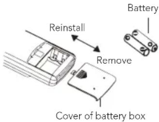
- Press the back side of remote controller marked the cover of battery box along the arrow direction.
- Replace two 7# (AAA 1.5V) dry batteries, and make sure the position of "+" polar and "-" polar are correct.
- Reinstall the cover of battery box.
NOTE
- During operation, point the remote control signal sender at the receiving window on indoor unit.
-
The distance between signal sender and receiving window should be no more than 8m, and there should be no obstacles between them.
-
Signal may be interfered easily in the room where there is fluorescent lamp or wireless telephone; remote controller should be close to indoor unit during operation.
- Replace new batteries of the same model when replacement is required.
- When you don't use remote controller for a long time, please take out the batteries.
- If the display on remote controller is fuzzy or there's no display, please replace batteries.
EMERGENCY OPERATION
If remote controller is lost or damaged, please use auxiliary button to turn on or turn off the air conditioner. The operation in details are as below: As shown in the figure Open panel, press aux. button to turn on or off the air conditioner. When the air conditioner is turned on, it will operate under auto mode.
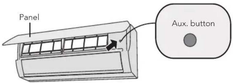
Warning: Use insulated object to press the auto button.
CLEANING AND MAINTENANCE
Warning:
- Turn off the air conditioner and disconnect the power before cleaning the air conditioner to avoid electric shock.
- Do not wash the air conditioner with water to avoid electric shock.
- Do not use volatile liquid to clean the air conditioner.
CLEAN SURFACE OF INDOOR UNIT
When the surface of indoor unit is dirty, it is recommended to use a soft dry cloth or wet cloth to wipe it.
Note: Do not remove the panel when cleaning it.
CLEAN FILTER
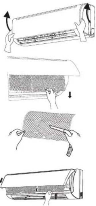
1. Open panel
Pull out the panel to a certain angel as shown in figure.
2. Remove filter
Remove the filter as indicated in the figure.
3. Clean filter
Use dust catcher or water to clean the filter. When the filter is very dirty use water (below 45^ C) to clean it, and then put it in a shady place and cool place to dry.
4. Install filter
Install the filter and then close the panel cover thightly.
Warning:
- The filter should be cleaned every three months. If there is much dust in the operation environment, clean frequency can be increased.
• After removing the filter, do not touch fins to avoid injury. - Do not use fire or hair dryer to dry the filter to avoid deformation or fire hazard.
CHECKING BEFORE USE-SEASON
- Check whether air inlets are blocked.
- Check whether air switch, plug and socket are in good condition.
- Check whether filter is clean
- Check whether drainage pipe is damaged.
CHECKING AFTER USE-SEASON
- Disconnect power supply.
- Clean filter and indoor unit's panel
TROUBLESHOOTING
| Problem Possible reasons Solutions | ||
| Indoor unit can't receive remote controller's signal or remote controller has no action. | Whether it's interfered severely (such as static electricity, stable voltage)? | Pull out the plug. Reinsert the plug after about 3min, and then turn on the unit again. |
| Whether remote controller is within the signal receiving range? | Signal receiving range is 8m. | |
| Whether there are obstacles? | Remove obstacles. | |
| Whether remote controller is pointing at the receiving window? | Select proper angle and point the remote controller at the receiving window on indoor unit. | |
| Is sensitivity of remote controller low; fuzzy display and no display? | Check the batteries. If the power of batteries is too low, please replace them. | |
| No display when operating remote controller? | Check whether remote controller appears to be damaged. If yes, replace it. | |
| Fluorescent lamp in room? | Take the remote controller close to indoor unit. | |
| Turn of the fluorescent lamp and then try it again. | ||
| No air emitted from indoor unit | Air inlet or air outlet of indoor unit is blocked? | Eliminate obstacles. |
| Under heating mode, indoor temperature is reached to set temperature? | After reaching to set temperature, indoor unit will stop blowing out air. | |
| Heating mode is turned on just now? | In order to prevent blowing out cold air, indoor unit will be started after delaying for several minutes, which is a normal phenomenon. | |
EN
EN
| Air conditioner can't operate | Power failure? | Wait until power recovery. |
| Is plug loose? | Reinsert the plug. | |
| Air switch trips off or fuse is burnt out? | Ask professional to replace air switch or fuse. | |
| Wiring has malfunction? | Ask professional to replace it. | |
| Unit has restarted immediately after stopping operation? | Wait for 3min, and then turn on the unit again. | |
| Whether the function setting for remote controller is correct? | Reset the function | |
| Mist is emitted from indoor unit's air outlet | Indoor temperature and humidity is high? | Because indoor air is cooled rapidly. After a while, indoor temperature and humidity will be decrease and mist will disappear. |
| Set temperature can't be adjusted | Unit is operating under auto mode? | Temperature can't be adjusted under auto mode. Please switch the operation mode if you need to adjust temperature. |
| Your required temperature exceeds the set temperature range? | Temperature range: 16-30. for Heating mode 8-30. | |
| Cooling (heating) effect is not good. | Voltage is too low? | Wait until the voltage resumes normal. |
| Filter is dirty? | Clean the filter. | |
| Set temperature is in proper range? | Adjust temperature to proper range. | |
| Door and window are open? | Close door and window. | |
| Odours are emitted | Whether there's odour source, such as furniture and cigarette, etc. | Eliminate the odour source. Clean the filter |
| Air conditioner operates abnormally | Whether there's interference, such as thunder, wireless devices, etc. | Disconnect power, put back power, and then turn on the unit again. |
| "Water flowing" noise | Air conditioner is turned on or turned off just now? | The noise is the sound of refrigerant flowing inside the unit, which is a normal phenomenon. |
| Cracking noise Air conditioner is turned on or turned off just now? | This is the sound of friction caused by expansion and/or contraction of panel or other parts due to the change of temperature. | |
ERROR CODE
When air conditioner status is abnormal, temperature indicator on indoor unit will blink to dispaly corresponding error code. Please refer to below list for identification of error code.
Error code Troubleshooting
E5 Over current protection: Unstable supply voltage, the heat exchangers are too dirty, fan speed is not normal, compresor failure, oil or gas leak.
E8 High temperature resistant protection: Refrigerant leak, fan motor failure, too dirty dust filters or heat exchangers.
U8 Indoor fan motor malfunction: Fan motor failure, Indoor PCB failure.
H6 Lock of indoor fan motor: Fan motor is broken, fan motor is blocked.
E6 Communication malfunction: Wrong wiring between indoor and outdoor unit, PCB indoor/outdoor malfunction.
C5 Malfunction of jumper cap: Missing jumper cap on PCB indoor, PCB is broken.
F0 Refrigerant recovery mode: Leakage of refrigerant, refrigerant catering
F1 Indoor ambient sensor is broken.
F2 Indoor evaporator sensor is broken.
Note: If there're other error codes, please contact qualified professionals for service.
WARNING
When below phenomenon occurs, please turn off air conditioner and disconnect power immediately, and then contact the dealer or qualified professionals for service.
• Power cord is overheating or damaged.
- There's abnormal sound during operation.
• Air switch trips off frequently.
• Air conditioner gives off burning smell.
- Indoor unit is leaking.
Do not repair or refit the air conditioner by yourself. If the air conditioner operates under abnormal conditions, it may cause malfunction, electric shock or fire hazard.

EN
GUARANTEE
Wilfa issues a 7 year guarantee on this product from the day of purchase is done. The guarantee covers production failure or defects that arise during the guarantee period. Your purchase receipt works as proof towards retailer if claiming your guarantee.
The guarantee is valid only for products that are bought and used in private households. The guarantee is not valid if the product is used commercially. The guarantee is not valid if the product is misused, used by negligence, if not following instructions given by Wilfa, if modified or if unauthorized reparation is done. The guarantee is also not valid for normal wear of the product, misuse, lack of maintenance, use of wrong electrical voltage or:
• Overloading of product
• Parts which are normally worn down
- Parts you can expect being replaced regularly (e.g. filter, battery etc.)
Instructions manual is also available at our website wilfa.com
PRODUCT SPECIFICATIONS
220V\~240V\~50Hz
SUPPORT AND SPARE PARTS
For support please visit us at wilfa.com, and see our customer service/support page. Here you will find frequently asked questions, spare parts, tips and tricks and all our contact information.
RECYCLABILITY
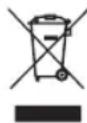
This marking indicates that this product should not be disposed with other household wastes throughout the EU. To prevent possible harm to the environment or human health from uncontrolled waste disposal, recycle it responsibly to promote the sustainable reuse of material resources. To return your used device, please use the return and collection systems or contact the retailer where the product was purchased. They can take this product for environmentally safe recycling free of charge.
EN
NO
INNHOLD
36 VIKTIGE SIKKERHETSANVISNINGER – DRIFT OG VEDLIKEHOLD
38 VIKTIGE SIKKERHETSANVISNINGER - TILKOBLING
41 KJ∅LEVÆSKE
45 ARBEIDSTEMPERATUR OMRÅDE
46 PRODUKTOVERSIKT
48 BRUK
54 DRIFTSVEILEDNING
55 N∅DDRIFT
55 RENGJ∅RING OG VEDLIKEHOLD
57 FEILS∅KING
60 FEILKODE
62 GARANTI
63 PRODUKTSPESIFIKASJONER
63 SUPPORT OG RESERVEDELER
63 GJENVINNING
VIKTIGE SIKKERHETSANVISNINGER – DRIFT OG VEDLIKEHOLD
natural_image
Four black-and-white icons: warning triangle with flame, open book, open icon with 'i', and open book with wrench (no text or symbols)ADVARSLER!
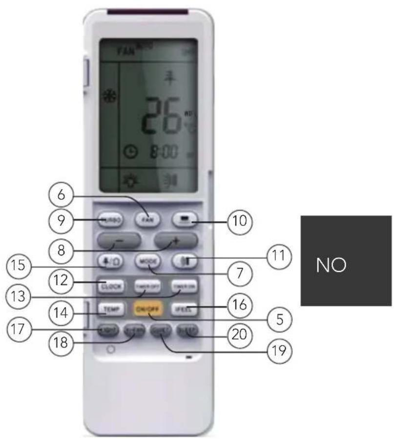
- AV/PÅ-knapp
- VIFTE-knapp
- MODUS-knapp
- +/- knapp
- AV/PÄ-knapp
- VIFTE-knapp
- MODE-knapp
- +/- knapp
- TURBO-knapp
- -knapp
-
-knap
-
KLOKKE-knapp
- TIMER AV/TIMER PÅ-knapp
- TEMP-knapp
- / -knapp
- KOMFORT-knapp
- LYS-knapp
- WI-FI-knapp
19 STILLE-knapp
20 HVILE-knapp
DISPLAYSKJERM
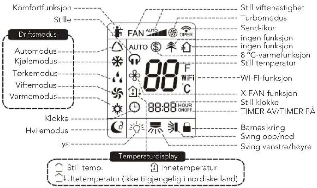
Advarsel:
natural_image
Four black-and-white icons: warning triangle with flame, open book, open icon with 'i', and open notebook with wrench (no text or symbols)FÖRSIKTIGHET
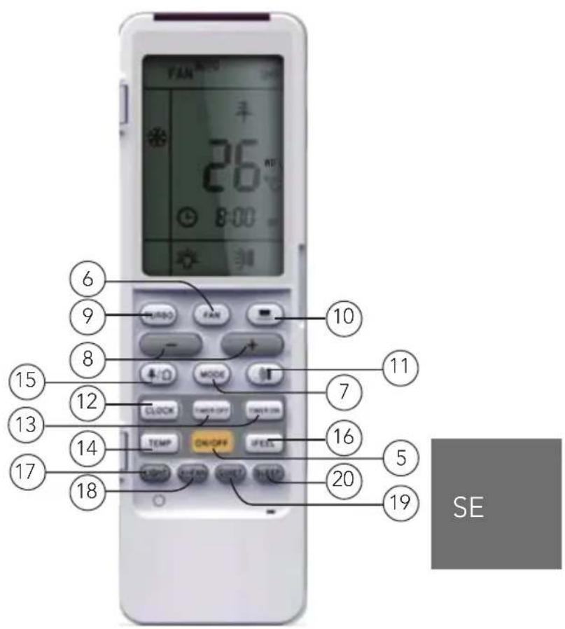
- ON/OFF-knapp
- FAN-knapp
- MODE-knapp
- (+)-knapp/(-)-knapp
- ON/OFF-knapp
- FAN-knapp
- MODE-knapp
- (+)-knapp/(-)-knapp
- TURBO-knapp
- -knapp
-
-knap
-
CLOCK-knapp
- TIMER ON/TIMER OFF-knapp
- TEMP-knapp
- / -knapp
- I FEEL-knapp
- LIGHT-knapp
- WIFI-knapp
19 QUIET-knapp
20 SLEEP-knapp
DISPLAYFÖNSTER
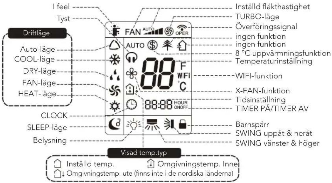
flowchart
graph LR
    A["AUTO"] --> B["Segment Bar 1"]
    B --> C["Segment Bar 2"]
    C --> D["Segment Bar 3"]
    D --> E["Segment Bar 4"]
    E --> F["Segment Bar 5"]
    F --> G["Segment Bar 6"]
    G --> H["Segment Bar 7"]
    H --> I["Segment Bar 8"]
    I --> J["Segment Bar 9"]
    J --> K["Segment Bar 10"]
    K --> L["Segment Bar 11"]
    L --> M["Segment Bar 12"]
    M --> N["Segment Bar 13"]
    N --> O["Segment Bar 14"]
    O --> P["Segment Bar 15"]
    P --> Q["Segment Bar 16"]
    Q --> R["Segment Bar 17"]
    R --> S["Segment Bar 18"]
    S --> T["Segment Bar 19"]
    T --> U["Segment Bar 20"]
    U --> V["Segment Bar 21"]
    V --> W["Segment Bar 22"]
    W --> X["Segment Bar 23"]
    X --> Y["Segment Bar 24"]
    Y --> Z["Segment Bar 25"]
④/⑧ (+)-knapp/(-)-knapp
Varning:
natural_image
Four black-and-white icons representing warning symbols, an open book, an open book with a 'i' symbol, and an open notebook with a wrench (no text or labels)SIKKERHEDSFORANSTALTNINGER
DK
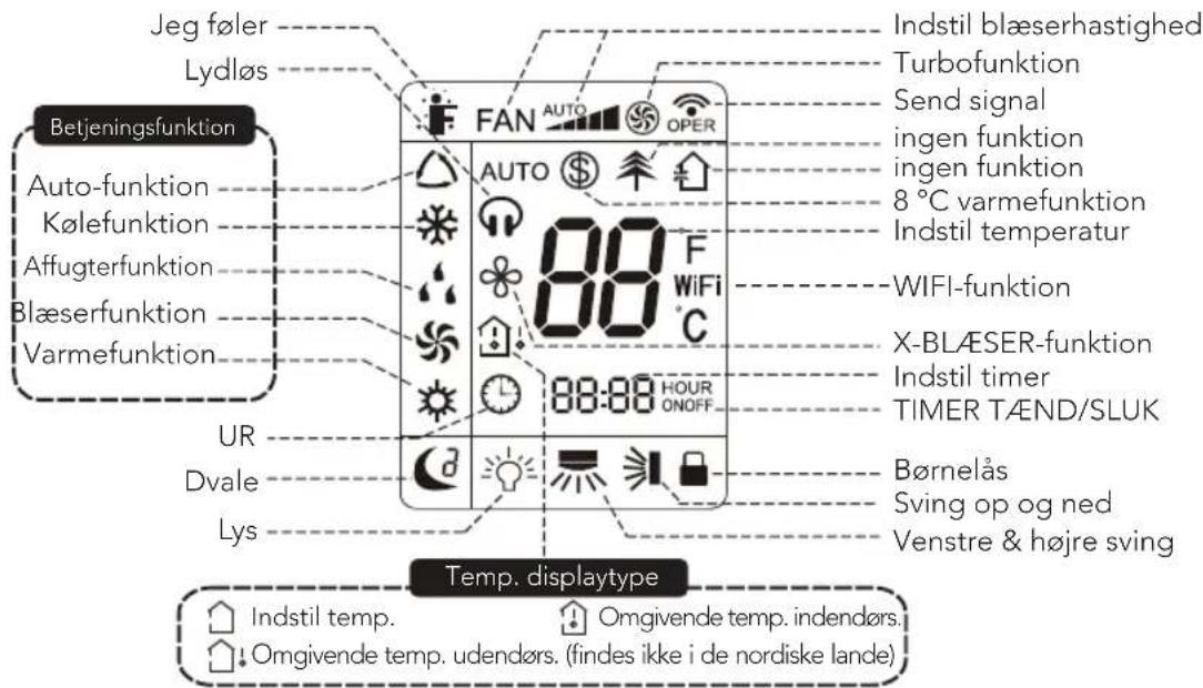
DK
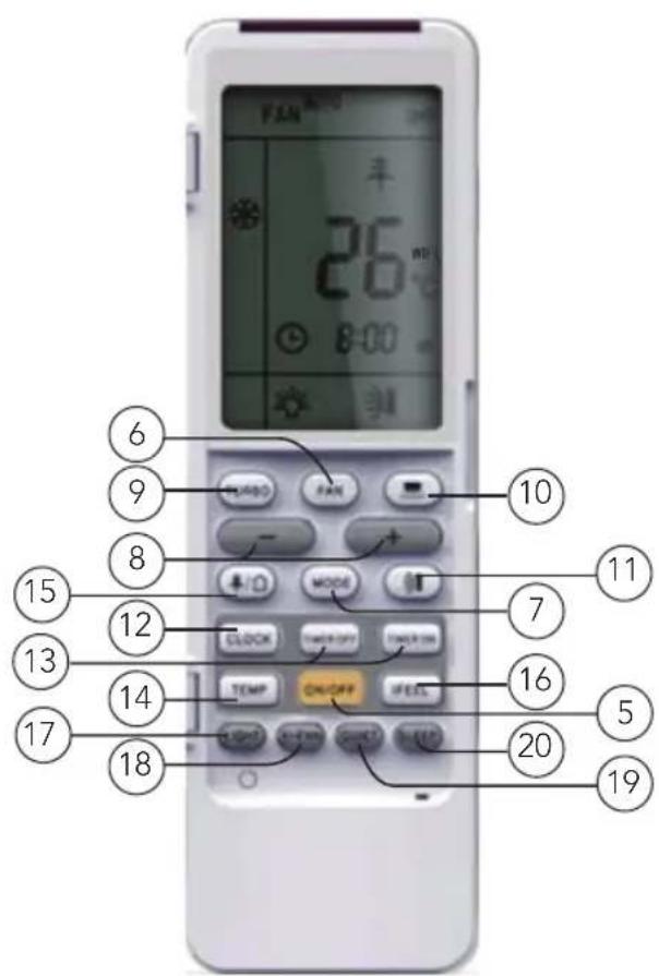
- START/STOP-knap
- BLÆSER-knap
- MODE-knap
- +/- knap
- START/STOP-knap
- BLÆSER-knap
- MODE-knap
- +/- knap
- TURBO-knap
- knap
-
knap
-
UR-knap
13.TIMERSTART/STOP-knap - TEMP-knap
- knap
- JEG F∅LER-knap
- LYS-knap
- WIFI-knap
- LYDL∅S-knap
- DVALE-knap
DISPLAY
Advarsel:
F
FI
- Virtapainike
- FAN-puhallinpainike
- MODE-tilapainike
- Plus-/miinuspainike
- Virtapainike
- FAN-puhallinpainike
- MODE-tilapainike
- Plus-/miinuspainike
- Turbopainike
- -painke
-
-pairike
-
CLOCK-kellopainike
- TIMER ON / TIMER OFF -ajastinpainike
- TEMP-lämpötilapainike
- / -painike
- I FEEL -painike
- LIGHT-valopainike
- WIFI-painike
- QUIET-painike (hiljainen tila)
- SLEEP-uniajastuspainike
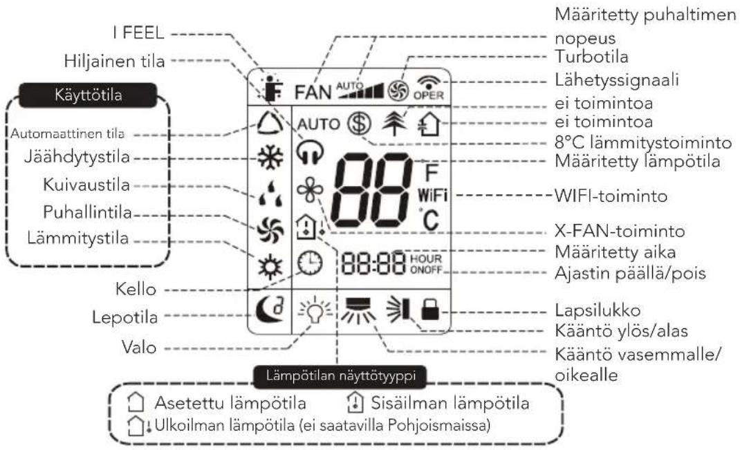
NÄYTTÖ
③/⑦ MODE-tilapainike
flowchart
graph TD
    A["ei näyttöä"] --> B["House Icon"]
    B --> C["House Icon"]
    C --> D["House Icon"]
    D --> E["House Icon"]
    E --> F["House Icon"]
    F --> G["House Icon"]
    G --> H["House Icon"]
    H --> I["House Icon"]
    I --> J["House Icon"]
Varoitus:
NARVIK-25-35_20_02
- NARVIK 25 and 35
- IMPORTANT SAFETY INSTRUCTIONS – OPERATION AND MAINTENANCE
- EN
- IMPORTANT SAFETY INSTRUCTIONS – ATTACHMENT
- NOTE
- THE REFRIGERANT
- WARNING
- PRECAUTIONS
- WORKING TEMPERATURE RANGE
- NARVIK 35
- PRODUCT OVERVIEW
- INDOOR UNIT
- HOW TO USE
- INTRODUCTION FOR BUTTONS ON REMOTE CONTROLLER
- Note:
- ①/⑤ ON/OFF button
- ②/⑥ FAN button
- ③/⑦ MODE button
- ④/⑧ +/- button
- ⑨ TURBO button
- ⑩ button
- ⑪ button
- ⑫ CLOCK button
- ⑬ TIMER ON/TIMER OFF button
- ⑭ TEMP button
- ⑯ I FEEL button
- ⑰ LIGHT button
- ⑱ WIFI button
- ⑲ QUIET button
- ⑳ SLEEP button
- In Heat mode:
- Combination of "TEMP" and "CLOCK" buttons:
- About Energy - saving Function
- About 8°C Heating Function
- CHILDLOCK FUNCTION
- TEMPERATURE DISPLAY SWITCHOVER FUNCTION
- WIFI FUNCTION
- OPERATION GUIDE
- REPLACEMENT OF BATTERIES IN REMOTE CONTROLLER
- EMERGENCY OPERATION
- CLEANING AND MAINTENANCE
- Warning:
- CLEAN SURFACE OF INDOOR UNIT
- CLEAN FILTER
- Open panel
- Remove filter
- Clean filter
- Install filter
- CHECKING BEFORE USE-SEASON
- CHECKING AFTER USE-SEASON
- ERROR CODE
- Error code Troubleshooting
- GUARANTEE
- PRODUCT SPECIFICATIONS
- SUPPORT AND SPARE PARTS
- RECYCLABILITY
- INNHOLD
- VIKTIGE SIKKERHETSANVISNINGER – DRIFT OG VEDLIKEHOLD
- ADVARSLER!
- Advarsel:
- FÖRSIKTIGHET
- ④/⑧ (+)-knapp/(-)-knapp
- Varning:
- SIKKERHEDSFORANSTALTNINGER
- ③/⑦ MODE-tilapainike
- Varoitus:
Brand : WILFA
Model : Narvik 35
Category : Heat pump