
Trysil 6500 - Heat pump WILFA - Free user manual and instructions
Find the device manual for free Trysil 6500 WILFA in PDF.


| Brand | Wilfa |
| Model | Trysil 6500 |
| Product Type | Heat pump (air conditioner with heating and cooling) |
| Refrigerant | R32 (flammable) |
| Operating Modes | Auto, Cool, Dry, Fan, Heat |
| Air Purifying Filter | Titanium Apatite Photocatalytic filter (washable, replace every 3 years) |
| Remote Control | Universal remote with LCD display, batteries: 2x AAA 1.5V |
| Timer Functions | Auto-on (T-ON) and Auto-off (T-OFF) programmable |
| Sleep Modes | Sleep 1, Sleep 2, Sleep 3 (DIY sleep curve) |
| Turbo Function | Quickly reach set temperature in Cool or Heat mode |
| Quiet Function | Reduces fan noise in Auto Quiet or Quiet mode |
| I Feel Function | Adjusts temperature based on remote sensor |
| Display Light | Can be turned on/off via remote |
| WiFi Connectivity | Not available on this model (“without this function”) |
| Safety Features | Automatic defrost, anti-freeze protection, anti-cold wind, overcurrent protection |
| Maintenance | Clean air filters weekly; wash photocatalytic filter every 6 months; replace every 3 years |
| Power Supply | 230V/50Hz (typical for European models) |
Frequently Asked Questions - Trysil 6500 WILFA
User questions about Trysil 6500 WILFA
0 question about this device. Answer the ones you know or ask your own.
Ask a new question about this device
Download the instructions for your Heat pump in PDF format for free! Find your manual Trysil 6500 - WILFA and take your electronic device back in hand. On this page are published all the documents necessary for the use of your device. Trysil 6500 by WILFA.
USER MANUAL Trysil 6500 WILFA
natural_image
White Wilfa air conditioner unit with ventilation grilles and control panel (no visible text or symbols)Wilfa Trysil Floor Comfort
Air Conditioner
Bruksanvisning
Bruksanvisning
Operating Instructions
LES ALLE ANVISNINGER F∅R BRUK
LÄS IGENOM ALLA INSTRUKTIONER INNAN PRODUKTEN ANVÄNDS
LÆS ALLE VEJLEDNINGER INDEN BRUG
LUE OHJEET HUOLELLISESTI ENNEN KÄYTTÖÄ
READ ALL INSTRUCTIONS BEFORE USING
flowchart
graph TD
    A["Start"] --> B["Arrow to '1'"]
    B --> C["Arrow to '2'"]
    C --> D["Arrow to '3'"]
    D --> E["Arrow to '4'"]
    E --> F["Arrow to '5'"]
    F --> G["Arrow to '6'"]
    G --> H["Arrow to '7'"]
    H --> I["Arrow to '8'"]
    I --> J["Arrow to '9'"]
    J --> K["Arrow to '10'"]
    K --> L["Arrow to '11'"]
    L --> M["Arrow to '12'"]
    M --> N["Arrow to '13'"]
    N --> O["Arrow to '14'"]
    O --> P["Arrow to '15'"]
    P --> Q["Arrow to '16'"]
    Q --> R["Arrow to '17'"]
    R --> S["Arrow to '18'"]
    S --> T["Arrow to '19'"]
    T --> U["Arrow to '20'"]
    U --> V["Arrow to '21'"]
    V --> W["Arrow to '22'"]
    W --> X["Arrow to '23'"]
    X --> Y["Arrow to '24'"]
    Y --> Z["Arrow to '25'"]
    Z --> AA["Arrow to '26'"]
    AA --> AB["Arrow to '27'"]
    AB --> AC["Arrow to '28'"]
    AC --> AD["Arrow to '29'"]
    AD --> AE["Arrow to '30'"]
    AE --> AF["Arrow to '31'"]
    AF --> AG["Arrow to '32'"]
    AG --> AH["Arrow to '33'"]
    AH --> AI["Arrow to '34'"]
    AI --> AJ["Arrow to '35'"]
    AJ --> AK["Arrow to '36'"]
    AK --> AL["Arrow to '37'"]
    AL --> AM["Arrow to '38'"]
    AM --> AN["Arrow to '39'"]
    AN --> AO["Arrow to '40'"]
    AO --> AP["Arrow to '41'"]
    AP --> AQ["Arrow to '42'"]
    AQ --> AR["Arrow to '43'"]
    AR --> AS["Arrow to '44'"]
    AS --> AT["Arrow to '45'"]
    AT --> AU["Arrow to '46'"]
    AU --> AV["Arrow to '47'"]
    AV --> AW["Arrow to '48'"]
    AW --> AX["Arrow to '49'"]
    AX --> AY["Arrow to '50'"]
    AY --> AZ["Arrow to '51'"]
    AZ --> BA["Arrow to '52'"]
    BA --> BB["Arrow to '53'"]
    BB --> BC["Arrow to '54'"]
    BC --> BD["Arrow to '55'"]
    BD --> BE["Arrow to '56'"]
    BE --> BF["Arrow to '57'"]
    BF --> BG["Arrow to '58'"]
    BG --> BH["Arrow to '59'"]
    BH --> BI["Arrow to '60'"]
    BI --> BJ["Arrow to '61'"]
    BJ --> BK["Arrow to '62'"]
    BK --> BL["Arrow to '63'"]
    BL --> BM["Arrow to '64'"]
    BM --> BN["Arrow to '65'"]
    BN --> BO["Arrow to '66'"]
    BO --> BP["Arrow to '67'"]
    BP --> BQ["Arrow to '68'"]
    BQ --> BR["Arrow to '69'"]
    BR --> BS["Arrow to '70'"]
    BS --> BT["Arrow to '71'"]
    BT --> BU["Arrow to '72'"]
    BU --> BV["Arrow to '73'"]
    BV --> BW["Arrow to '74'"]
    BW --> BX["Arrow to '75'"]
    BX --> BY["Arrow to '76'"]
    BY --> BZ["Arrow to '77'"]
    BZ --> CA["Arrow to '78'"]
    CA --> CB["Arrow to '79'"]
    CB --> CC["Arrow to '80'"]
    CC --> CD["Arrow to '81'"]
    CD --> CE["Arrow to '82'"]
    CE --> CF["Arrow to '83'"]
    CF --> CG["Arrow to '84'"]
    CG --> CH["Arrow to '85'"]
    CH --> CI["Arrow to '86'"]
    CI --> CJ["Arrow to '87'"]
    CJ --> CK["Arrow to '88'"]
    CK --> CL["Arrow to '89'"]
    CL --> CM["Arrow to '90'"]
    CM --> CN["Arrow to '91'"]
    CN --> CO["Arrow to '92'"]
    CO --> CP["Arrow to '93'"]
    CP --> CQ["Arrow to '94'"]
    CQ --> CR["Arrow to '95'"]
    CR --> CS["Arrow to '96'"]
    CS --> CT["Arrow to '97'"]
    CT --> CU["Arrow to '98'"]
    CU --> CV["Arrow to '99'"]
    CV --> CW["Arrow to '100'"]
Dette er en universal fjernkontroll. Hvis du velger ⚡️, ⚡️, eller ⚡️ vil enheten velge ⚡️. ⚡️ indikerer denne svingvinkelen som: ⚡️ ⚡️ ⚡️ ⚡️ ⚡️
71 FEEL
VEDLIKEHOLD
natural_image
Diagram of a device with arrows indicating flow or movement, no text or symbols present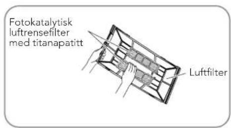
natural_image
Illustration of two hands holding a grid-based device and a cylindrical tool (no text or symbols)Fotokatalytisk luftrensefilter med titanapatitt
PRODUKTÖVERSIKT – FJÄRRKONTROLL
WiFi (utan denna funktion)
① ON/OFF
UNDERHÅLL
natural_image
Diagram of a device with arrows indicating flow or movement, no text or symbols present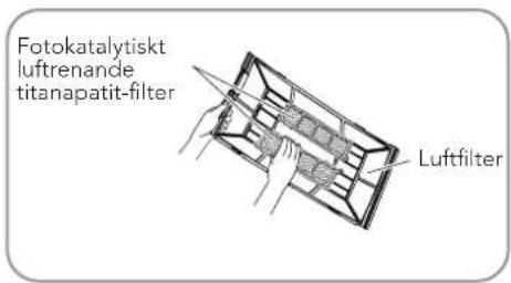
natural_image
Illustration of two hands holding a grid-patterned panel, one with a tool and the other with a magnifying glass (no text or symbols)Åbn frontpanelet.
Tryk for at starte driften
② -
VEDLIGEHOLDELSE
Bemærk:
natural_image
Diagram of a device with arrows indicating flow or movement, no text or symbols present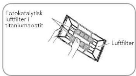
natural_image
Illustration of two hands holding a grid-based device and a cylindrical tool (no text or symbols)Fotokatalytisk luftfilter i titaniumapatit
KUNNOSSAPITO
natural_image
Diagram of a device with arrows indicating airflow or movement, showing internal components (no text or symbols)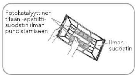
natural_image
Illustration of two hands holding a 3D grid device and a cylindrical device (no text or symbols)Read all instructions before use. Read carefully and keep for future reference.
IMPORTANT SAFETY INSTRUCTIONS – OPERATION AND MAINTENANCE. 5
IMPORTANT SAFETY INSTRUCTIONS – ATTACHMENT....6
Operating temperature range 7
Product overview – indoor unit and outdoor unit....8
Product overview – remote control....9
Introduction to buttons on remote control 10
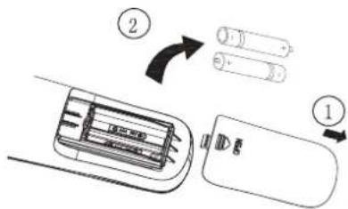
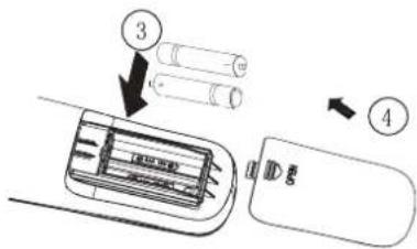
Replacement of batteries 13
Maintenance....13
Operating guide 15
Operating precautions....16
Troubleshooting 16
Error codes.... 17
IMPORTANT SAFETY INSTRUCTIONS – OPERATION AND MAINTENANCE
- This unit can be used by children aged 8 years and older as well as persons with reduced physical, sensory or mental capacity, or those who lack relevant experience and knowledge, provided they are given supervision or instruction concerning the safe use of the unit and understand the hazards involved.
• Children should not play with the unit.
- Cleaning and user maintenance should not be performed by children without supervision.
- Do not connect the air conditioner to a multi-plug outlet as this may cause a fire hazard.
- Disconnect the power supply when cleaning the air conditioner in order to avoid electric shock.
- If the power supply cord is damaged, it must be replaced by the manufacturer, its service agent or a similarly qualified person in order to avoid an electrical hazard.
- Do not wash the air conditioner with water as this may result in electric shock.
- Do not spray water on the indoor unit as this may cause electric shock or malfunction.
- After removing the filter, do not touch the fins in order to avoid injury. Do not use a hair dryer or any device with open flames to dry the filter in order to avoid a fire hazard or damage to the unit.
- Maintenance must be performed by qualified professionals in order to avoid personal injury or damage to the unit.
- Do not repair the air conditioner on your own. This may cause electric shock or damage. Please contact the dealer when you need to repair the air conditioner.
- Do not insert fingers or objects into the air inlet or air outlet as this may cause personal injury or damage.
- Do not block the air outlet or air inlet as this may cause malfunction.
- Do not spill water on the remote control as this may cause the remote control device to malfunction.
- If any of the following occurs, please turn off the air conditioner, disconnect the power immediately, and then contact the dealer or a qualified professional for service.
- The power cord is overheating or damaged.
- An abnormal sound occurs during operation.
– The circuit breaker trips frequently.
- The air conditioner emits a burning odour.
– The indoor unit is leaking.
- If the air conditioner is operated under abnormal conditions, it may cause malfunction, an electric shock or a fire hazard.
- When turning the unit on or off via the emergency operation switch, please use an insulated object other than metal to turn the switch.
- Do not step or place heavy objects on the top panel of the outdoor unit. This may cause damage or personal injury.
IMPORTANT SAFETY INSTRUCTIONS – ATTACHMENT
- Installation must be performed by qualified professionals to avoid personal injury or damage to the unit.
- The electrical safety regulations must be followed when installing the unit.
- Use a power supply and circuit breaker which are in compliance with local safety regulations.
- A circuit breaker must be installed in order to avoid malfunction. An all-pole disconnection switch which has contact separation of at least 3mm on all poles should be connected to the fixed wiring.
- For a circuit breaker with suitable capacity, please consult the following table. The air switch should include a magnet buckle and heating buckle function as these can protect against short circuits and overloads.
- The air conditioner should be properly grounded. Incorrect grounding may result in electric shock.
- Use only approved power cords.
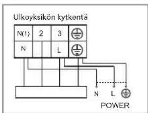
- Ensure the power supply matches the requirements of the air conditioner. An unstable power supply or incorrect wiring may result in malfunction. Appropriate power supply cables should be installed before using the air conditioner.
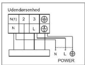
- Correctly connect the live wire, neutral wire and grounding wire of the power socket.
- Be sure to turn off the power supply before performing any work related to electricity.
- Do not turn the power on before finishing the installation. If the supply cord is damaged, it must be replaced by the manufacturer, its service agent or a similarly qualified person in order to avoid an electrical hazard.
- The temperature of the refrigerant circuit will be high. Please keep the interconnection cable away from the copper tubing.
- The unit should be installed in accordance with local or national wiring regulations.
- An air switch having contact separation of at least 3mm on all poles should be connected to the fixed wiring.
-
The air switch must include functions for magnetic tripping and heat tripping in order to prevent short circuits or overloads. Please install an air switch with a suitable capacity in accordance with the sheet below.
-
Installation must be performed in accordance with NEC and CEC requirements by authorised personnel only.
- The air conditioner is a high quality electrical appliance. It must be properly grounded with a specialised grounding device by a professional. Please ensure the unit is always properly grounded in order to avoid electric shock.
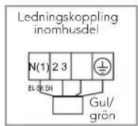
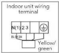
- The yellow-green wire in the air conditioner is a grounding wire, which may not be used for any other purpose.
- The grounding resistance should comply with national electrical safety regulations.
- The unit must be positioned so that the plug is accessible.
- All wires on the indoor unit and outdoor unit should be connected by a professional.
- If the length of the power connection wire is insufficient, please contact the supplier to request a new one. You should avoid extending the wire on your own.
- For an air conditioner with a plug, the plug should be reachable after finishing the installation.
- For an air conditioner without a plug, a circuit breaker must be installed on the line.
- If the air conditioner needs to be moved to another location, this work should only be performed by a qualified professional in order to avoid personal injury or damage to the unit.
- Select a location which is out of reach of children and is distant from animals and/or plants. If this is unavoidable, fencing should be added to ensure safety.
- The indoor unit should be installed close to a wall
NOTE
To protect your customer rights, it is very important that you follow cleaning and service instructions carefully. Failure to do so may result in your rights being forfeited.
THE REFRIGERANT
- To realize the function of the air conditioner unit, a special refrigerant circulates in the system. The used refrigerant is the fluoride R32, which is specially cleaned. The refrigerant is flammable and inodorous.
Furthermore, it can lead to explosion under certain conditions. But the flammability of the refrigerant is very low. It can be ignited only by fire. - Compared to common refrigerants, R32 is a nonpolluting refrigerant with no harm to the ozonosphere. The influence upon the greenhouse effect is also lower. R32 has got very good thermodynamic features which lead to a really high energy efficiency. The units therefore need a less filling.
WARNING:
Do not use means to accelerate the defrosting process or to clean, other than those recommended by the manufacture. Should repair be necessary, contact your nearest authorized Service Centre. Any repairs carried out by unqualified personnel may be dangerous. The appliance shall be stored in a room without continuously operating ignition sources. (for example: open flames, an operating gas appliance or an operating electric heater.) Do not pierce or burn.
Appliance filled with flammable gas R32. For repairs, strictly follow manufacturer's instructions only. Be aware that refrigerants not contain odour.

PRODUCT OVERVIEW – INDOOR UNIT AND OUTDOOR UNIT
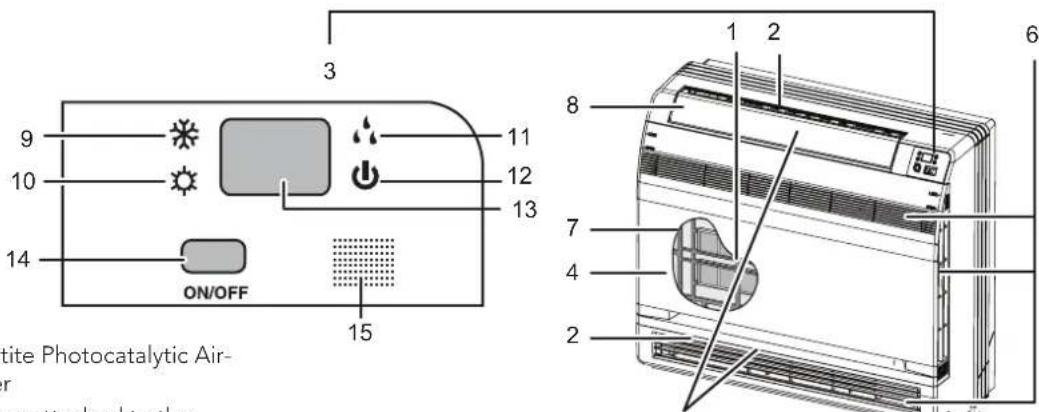
① Titanium Apatite Photocatalytic Air-Purifying Filter
• These filters are attached to the inside of the air filters
② Air outlet
③ Display
④ Front panel
⑤ Louvres – vertical blades (the louvres are on the inside of the air outlet)
⑥ Air inlet
⑦ Air inlet
⑧ Flap - horizontal blade
⑨ Cool mode light
⑩ Heat mode light
⑪ Dry mode light
⑫ Run light
⑬ LED display
⑭ Indoor unit ON/OFF switch
- Push this switch once to start operation, push once again to stop
• Cooling model in COOL mode has a temperature setting of 25^ C and an air flow rate of AUTO - Heat pump model in AUTO mode has a temperature setting of 25 °C and an air flow rate of AUTO
⑮ Signal receiver
- This receives signals from the remote control. When the unit recieves a signal, you will hear a short beep.
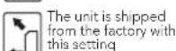
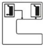
⑯ Air outlet selection switch
⑰ Room temperature sensor
• This senses the air temperature around the unit
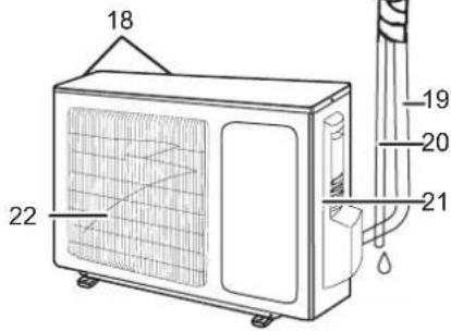
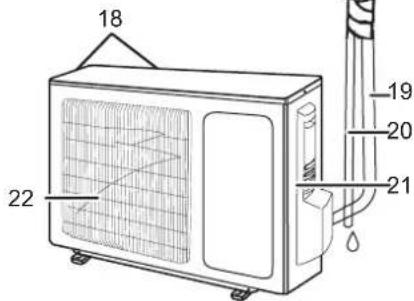
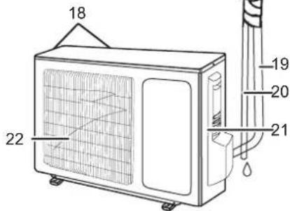
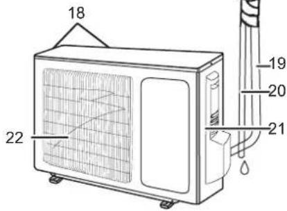
⑱ Air inlet: (Back and side)
⑲ Refrigerant tubing and inter-unit cable
20 Drain hose
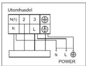
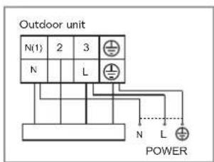
②1 Grounding terminal (inside cover)
22 Air outlet
Air outlet selection switch

natural_image
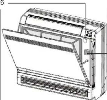
Technical line drawing of a front-end air conditioner unit with ventilation grilles and cooling fins (no text or symbols)Opening the front panel
Note:
- Before opening the front panel, be sure to stop the unit's operation and turn the circuit breaker OFF.
- Do not touch the metal parts on the inside of the indoor unit as this may result in injury
- If the supply cord is damaged, it must be replaced by the manufacturer, its service agent or a similarly qualified person in order to avoid an electrical hazard.
• This unit should be installed in accordance with national wiring regulations. - An all-pole disconnection switch which has contact separation of at least 3mm on all poles should be connected to the fixed wiring. For models with a power plug, make sure the plugs are within reach after installation.
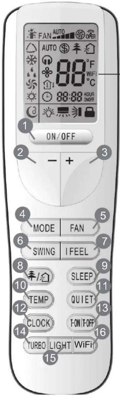
PRODUCT OVERVIEW - REMOTE CONTROL
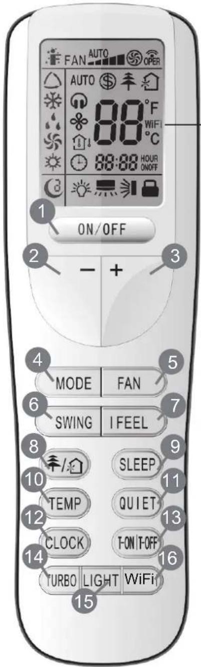
WiFi (without this function)
① ON/OFF
Press to start operation
② -
Press to decrease temperature setting.
③ +
Press to increase temperature setting.
④ MODE
Press to select operation mode (AUTO/COOL/DRY/FAN/HEAT).
⑤ FAN
Press to set fan speed.
⑥ SWING
Press to set swing angle.
⑦ I FEEL
⑧ OPTION ¥/
Press to set HEALTH or AIR function.
⑨ SLEEP
⑩ TEMP
① QUIET
Press to set QUIET function.
② CLOCK
Press to set clock.
③ T-ON T-OFF
Press to set auto-on /auto-off timer.
④ TURBO
⑤ LIGHT
Press to turn the light on/off.
⑥ WIFI
INTRODUCTION TO BUTTONS ON REMOTE CONTROL
Note:
This is a general use remote control. It can be used for air conditioners with multiple functions. For some functions which the model does not have, if the corresponding button is pressed on the remote control, the unit will maintain its original running status.
1 ON/OFF
Press this button to turn the unit on. Press this button again to turn the unit off.
2-
Press this button to decrease the temperature setting. Holding the button down for more than 2 seconds will rapidly decrease the temperature setting. In AUTO mode, the temperature setting is not adjustable.
3 +
Press this button to increase the temperature setting. Holding the button down for more than 2 seconds will rapidly increase the temperature setting. In AUTO mode, the temperature setting is not adjustable.
4 MODE
Each time you press this button, an operating mode is selected in the following sequence: AUTO, COOL, DRY, FAN, and HEAT*:
*Note: Only for models with a heating function.
After start up, the unit defaults to AUTO mode. In AUTO mode, the temperature setting will not be displayed on the LED of the indoor unit. The unit will automatically select a suitable operating mode in keeping with the room temperature in order to make the room comfortable.
5 FAN
This button is used for setting Fan Speed in the following sequence: AUTO, -, -, -, , and back to AUTO.

flowchart
graph LR
    A["Low speed"] --> B["Low-Medium speed"]
    B --> C["Medium speed"]
    C --> D["High speed"]
    D --> E["Medium-High speed"]
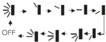
6 SWING
Press this button to set the up and down swing angle, which changes as indicated below:
flowchart
graph TD
    A["Light Beam"] --> B["OFF"]
    B --> C["Light Beam"]
    C --> D["ON/OFF"]
    D --> E["Light Beam"]
    E --> F["OFF"]
    F --> G["Light Beam"]
    G --> H["ON/OFF"]
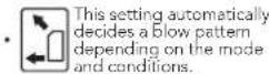
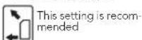
This remote control is universal. If any command , , or is sent, the unit will perform the command as . indicates the guide louvre swings as:
71 FEEL
Press this button to turn on the I FEEL function. The unit automatically adjusts the temperature according to the temperature sensed. Press this button again to cancel the I FEEL function.
8年/
Press this button to operate the on/off for the healthy and scavenging functions in operating status. Press this button for the first time to start the scavenging function; the LCD will display "☐". Press this button a second time to start the healthy and scavenging functions simultaneously; the LCD will display "☐" and "✗". Press this button a third time to exit the healthy and scavenging functions simultaneously. Press this button a fourth time to start the healthy function; the LCD will display "✗". Press this button again to repeat the operations above.
9 SLEEP
- Press this button to select Sleep 1 ( C^1 ), Sleep 2 ( C^2 ), Sleep 3 ( C^3 ) or to cancel Sleep. Scroll between these selections after the unit is powered on. Sleep Cancel is the default value.
- Sleep 1 is Sleep mode 1 in Cool, Dehumidify modes. The sleep status after running for one hour: the main unit temperature setting will increase by 1^ ; after two hours: the temperature setting will increase by 2^ and the unit will continue to run at this temperature setting. In Heat mode, the sleep status after running for one hour: the temperature setting will decrease by 1^ ; after two hours: the temperature setting will decrease by 2^ and the unit will continue to run at this temperature setting.
- Sleep 2 is Sleep mode 2, where the air conditioner will run according to a preset group of temperature settings along a sleep temperature curve.
- Sleep 3, which is a Sleep mode containing DIY sleep curve settings:
(1) In Sleep 3 mode, press and hold the "Turbo" button. The remote control will enter individual sleep setting status and will display "1 hour". The temperature setting field ("88") will display the corresponding temperature of the last setting in the sleep curve and flash. (The first entry will display in accordance with the initial sleep curve setting value from the factory);
(2) To adjust, use the "+" and "-" buttons to change the corresponding temperature setting. After adjustment is complete, press the "Turbo" button again to confirm;
(3) At this point the timer position on the remote control will automatically advance by 1 hour, i.e., to "2 hours", "3 hours", "8 hours", etc., The temperature setting field ("88") will display the corresponding temperature of the last setting in the sleep curve and flash;
(4) Repeat steps (2) - (3) above until 8 hours of temperature settings have been input. The sleep curve set up is now finished. At this point the remote control will revert to the original timer display and the temperature display will return to the original temperature setting. The Sleep 3 DIY sleep curve set up can be reviewed:
- The user can use the sleep curve setting method to review the preset sleep curve. Enter individual sleep setting status but do not change the temperature. Press the "Turbo" button directly to confirm. Note: In this presetting/review method, if no button is pressed continuously within 10 seconds, the sleep curve setting status will automatically exit and revert to the original display. Similarly, if the "ON/OFF", "Mode", "Timer" or "Sleep" buttons are pressed, the sleep curve setting/review status will also exit.
10 TEMP
Use this button to select display of the indoor temperature setting or the indoor ambient temperature. When the indoor unit is first powered on, it will display the temperature setting. If the temperature display status is changed from another status to "☐", it will display the ambient temperature. If within 5 seconds or 5 seconds later, the unit receives another remote control signal, this will return the display to the temperature setting. If the user has not set up the temperature display status, the unit will display the temperature setting.
11 QUIET
Use this button for Quiet status, which is available in Auto Quiet mode (display " 🔊" and "Auto" signal), Quiet mode (display " 🔊" signal) and Quiet OFF (no signal for " 🔊" is displayed). After powering on, the unit defaults to Quiet OFF. Note: the Quiet function cannot be set up in Fan and Dry mode; in Quiet mode (Display " 🔊" signal), the fan speed is not available.
12 CLOCK
Press the CLOCK button and ⏻ will flash. Within 5 seconds press the + or - button to adjust the present time. Holding down either button for more than 2 seconds will increase or decrease the time by 1 minute every 0.5 seconds and then by 10 minutes every 0.5 seconds. While the display is flashing after setting, press the CLOCK button again to confirm the setting and then ⏻ will constantly display.
13 T-ON / T-OFF
Press the T-ON button to initiate the auto-ON timer. To cancel the auto-timer program, simply press this button again.
After pressing this button, Ⓤ will disappear and "ON" will flash. 00:00 will be displayed for setting the ON time. Within 5 seconds, press the + or - button to adjust the time value. Each press of either button changes the time setting by 1 minute. Holding down either button rapidly changes the time setting by 1 minute and then 10 minutes. Within 5 seconds after setting the time, press the TIMER ON button to confirm.
Press the T-OFF button to initiate the auto-off timer. To cancel the auto-timer program, simply press the button again. Setting the TIMER OFF is the same process as for TIMER ON.
14 TURBO
Press this button to activate/deactivate the Turbo function which enables the unit to reach the preset temperature in the shortest possible time. In COOL mode, the unit will blow strong cooled air at a super high fan speed. In HEAT mode, the unit will blow strong heated air at a super high fan speed.
15 LIGHT
Press the LIGHT button to turn on the display light and press this button again to turn off the display light. If the light is turned on, 🎨 is displayed. If the light is turned off, 🎨 will disappear.
16 WIFI
Press the WIFI button to activate the function. Press again to stop the function. More info can be found in WIFI attachments and wilfa.no, wilfa.com
17 Combination of "+" and "-" buttons: Locking
Press the "+" and "-" buttons simultaneously to lock or unlock the keypad. If the remote control is locked, ■ will display. In this case, by pressing any button, ■ will flash three times.
18 Combination of "MODE" and "-" buttons: Switching between Centigrade and Fahrenheit.
At unit OFF, press the "MODE" and "-" buttons simultaneously to switch between °C and °F.
19 Combination of "TEMP" and "CLOCK" buttons: Energy-saving Function
Press "TEMP" and "CLOCK" simultaneously in COOL mode to start the energy-saving function. The display on the remote control will display "SE". Repeat the operation to exit the function.
20 Combination of "TEMP" and "CLOCK" buttons: 8°C Heating Function
Press "TEMP" and "CLOCK" simultaneously in HEAT mode to start the 8°C Heating Function. The display on the remote control will display " \$ " and a temperature setting of "8°C" (or 46°F, if applicable) will be adopted. Repeat the operation to exit the function.
21 Backlighting Function
The unit lights up for 4 seconds when powering on for the first time, and 3 seconds when activated later.
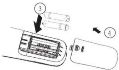
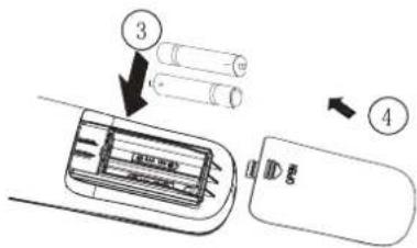
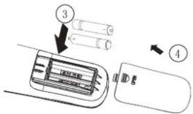
REPLACEMENT OF BATTERIES
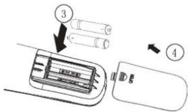
- Remove the battery cover plate from the rear of the remote control (as shown in the figure).
- Take out the old batteries.
- Insert two new AAA1.5V dry batteries and ensure the batteries are inserted in the correct direction.
- Replace the battery cover plate.
Notes:
- When replacing the batteries, do not use old or different types of batteries, as this may cause malfunction.
- If the remote control will not be used for a long period of time, please remove the batteries to prevent loss of charge.
• The operation should be performed within the reception range. - It should be kept 1m away from the TV set or stereo sound sets.
- If the remote control does not operate normally, please take the batteries out and reinsert them after 30 seconds. If it still does not operate properly, replace the batteries.
MAINTENANCE
Before inspection and maintenance on the unit, PLEASE turn the power switch to "OFF" to disconnect the power supply.
Units
Indoor unit, Outdoor unit and Remote control
- Wipe them with a soft, dry cloth.
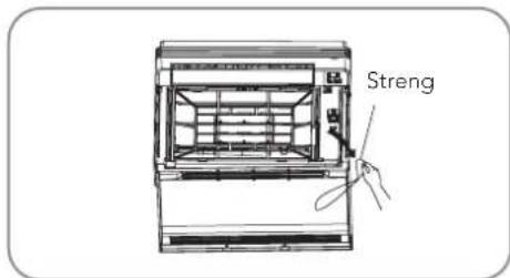
Front panel
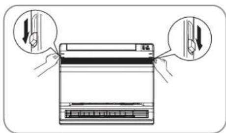
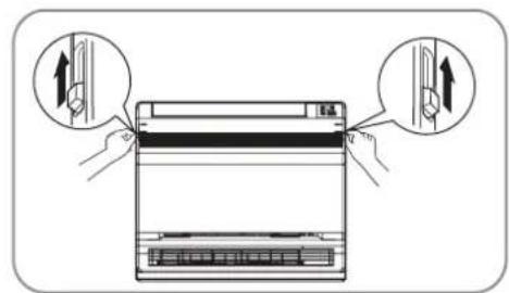
- Open the front panel. Slide the two stoppers on the left and right sides inward until they click.
-
Removing the front panel.
-
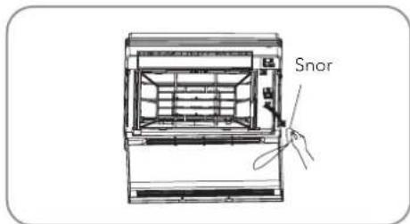
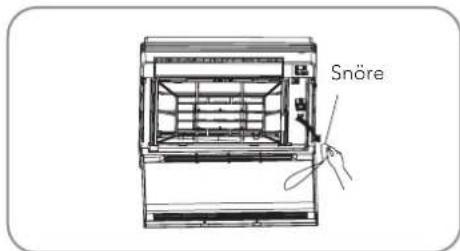
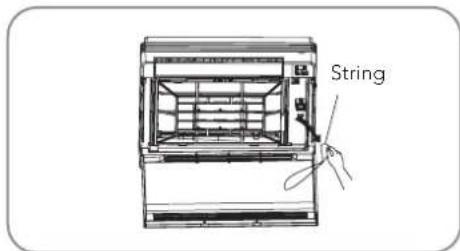
Remove the string.
- Allowing the front panel to fall forward will enable you to remove it.
-
Cleaning the front panel.
-
Wipe it with a soft cloth soaked in water
- Only neutral detergent may be used
- If washing the front panel with water, dry it with a cloth and allow it to dry in the shade after washing.
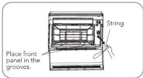
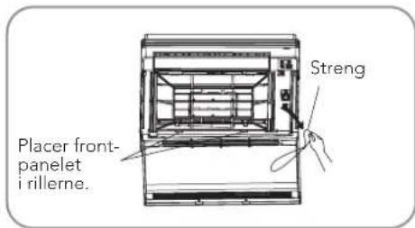
-
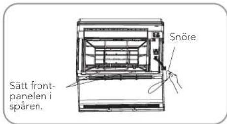
Attaching the front panel.
-
Insert the front panel into the grooves of the unit (3 places).
- Attach the string to the right, inner-side of the front grille.
- Close the panel slowly.
Note:
- Do not touch the metal parts of the indoor unit as touching these parts may cause injury.
- When removing or attaching the front panel, use a solid, stable stool and watch your step.
- When removing or attaching the front panel, support the panel securely with your hand to prevent it from falling.
- For cleaning, do not use hot water above 40 °C, benzene or other volatile oils, polishing compounds, scrubbing brushes, or other hard stuff.
• After cleaning, make sure that the front panel is securely fastened.
Filters
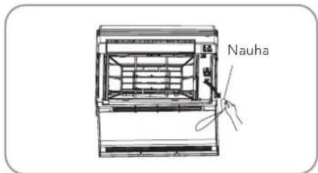
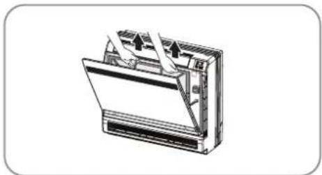
- Open the front panel.
- Remove the air filter.
- Press the claws on the right and left of the air filter down slightly, then pull upward.
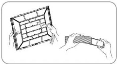
- Take out the Titanium Apatite Photocatalytic Air-Purifying Filter.
- Hold the tabs of the frame, and remove the claws in 4 places.
- Clean or replace each filter. See figure.
natural_image
Diagram of a device with arrows indicating flow or movement, no text or symbols present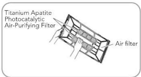
- Position the air filter and Titanium Apatite Photocatalytic Air-Purifying Filter as they were previously and close the front panel.
- Operation without air filters may result in problems as dust will accumulate inside the indoor unit.
- Wash the air filters with water or clean them with a vacuum cleaner.
- If the dust is not removed easily, wash the filters with neutral detergent diluted with lukewarm water, then allow them to dry in the shade.
- It is recommended to clean the air filters every week.
natural_image
Illustration of two hands holding a grid-based object, one with a pen and the other with a textured handle (no text or symbols)Titanium Apatite Photocatalytic Air-Purifying Filter
The Titanium Apatite Photocatalytic Air-Purifying Filter can be refreshed by washing it with water once every 6 months. We recommend replacing it once every 3 years.
Maintenance
- Vacuum out dust and soak in warm water or water for about 10 to 15 minutes if the dirt is heavy.
- Do not remove the filter from the frame when washing with water.
- After washing, shake off remaining water and allow to dry in the shade.
- As the material is made out of paper, do not wring the filter when removing water from it.
Replacement
Remove the tabs on the filter frame and replace with a new filter. Dispose of the old filter as flammable waste.
Note:
Operation with dirty filters:
• cannot deodorise the air.
- cannot clean the air.
• results in poor heating or cooling.
- may cause odour.
Before a long idle period
- Operate in "FAN only" mode for several hours on a fine day to dry out the inside.
- Press the "Mode" button and select "FAN" operation.
- Press the "ON/OFF" button and start operation.
- After operation stops, turn off the circuit breaker for the room air conditioner.
- Remove, clean and reinsert the air filters.
- Take out batteries from the remote control.
Before using after a long idle period
- Check that the base, stand and other fittings on the outdoor unit have not deteriorated or corroded.
- Check that nothing is blocking the air inlets and outlets of the indoor and outdoor units.
- Check that the drain water flows smoothly out of the drain hose during COOL or DRY operation. If no drain water is visible, water may be leaking from the indoor unit. Stop operation and contact the service agent if this is the case.
OPERATING GUIDE
Operating principle and special functions for cooling
Principle:
The air conditioner absorbs heat in the room and transmits/discharges this heat outdoors so that the indoor ambient temperature decreases. The unit's cooling capacity will increase or decrease depending on the outdoor ambient temperature.
Anti-freezing function:
If the unit is running in COOL mode and at a low temperature, frost will form on the heat exchanger. When the indoor heat exchanger temperature falls below 0 °C , the indoor unit microcomputer will stop the compressor from running and protect the unit.
Working principle and special functions for heating
Principle:
- The air conditioner absorbs heat from outdoors and transmits this indoors, thereby increasing room temperature. This is the heat pump heating principle. Heating capacity will fall depending on the decrease in the outdoor temperature.
- If the outdoor temperature becomes very low, please operate in conjunction with other heating equipment.
Defrosting:
- When the outdoor temperature is low but there is high humidity, after a long period of operation frost will form on the outdoor unit. This will impact the heating effect and at this point the auto-defrosting function will activate and the heating will cease to run for 8-10 minutes.
- During auto-defrosting, the fan motors of the indoor unit and outdoor unit will stop.
- During defrosting, the indoor indicator will flash and the outdoor unit may emit vapor. This is due to the defrosting and is not a malfunction.
• After defrosting is finished, the heating will be restored automatically.
Anti-cold wind function:
In Heat mode, if the indoor heat exchanger has not achieved a certain temperature, the indoor fan motor will not start, thus preventing the blowing of cool wind (within 3 minutes):
- The heat operation has just begun.
- After the auto-defrosting operation is finished.
- Heating at low temperatures.
The climate type of this unit is as noted on the nameplate.
- The temperature should not be set lower than what you need. Otherwise this will result in increased energy costs.
- To distribute cool air throughout the room, adjust the air flow direction as shown by the arrows (see picture) to diffuse the cool air.
- Clean the air filter every week for more efficient performance.
- Close windows and doors while operating the unit to prevent escape of cooled air and to save energy.
- Close curtains and/or glass windows when cooling to prevent heating of the room by sunlight, which may result in higher electricity costs.
- In the event of ineffective ventilation, occasionally open the window(s) to ventilate the room, though not so long that a significant amount of cooled air will escape.
OPERATING PRECAUTIONS
- Check the electrical system (voltage and frequency). Use the appropriate power supply, as indicated on the unit, to operate the air conditioner. Use only fuses with the specified capacity. Do not use loose wiring instead of fuses.
- Turn off the air conditioner if electricity interference occurs while running. If the unit is not to be used for a long period of time, turn off the main switch of the power supply.
- Do not insert objects into the air inlet or outlet when the air conditioner is running as this may cause damage or personal injury. Also pay special attention when children are present.
- Do not place any obstacle against the air flow direction of the indoor and outdoor unit. Inefficient performance or malfunction may result.
- Do not aim the air flow directly at people, especially infants, the elderly or medical patients.
- Do not place a heater or any other heat source close to the unit. The heat may degrade the plastic parts
TROUBLESHOOTING
Check the following items before contacting your service agent as you may find the solution to your problem(s). After reviewing this list, if the unit still does not operate, please contact your local dealer.
| Problem Check items | |
| Does not operate Check if the electrical wire is damaged & if | the circuit breaker switch is still on. |
| Check that the power supply is in order. | |
| Check if the timer switch is on or not. | |
| The air conditioner runs but does not cool sufficiently.. Check if the preset temperature is too high. | |
| Vapour, mist or fumes are coming from the unit while running. | Hot air in the room can mix with cool air and may cause smoke fumes. |
| Inoperative remote control. A loose or disconnected wire be | between the unit and the display. |
| Check if the batteries are inserted in the correct direction. | |
| Check if the batteries are dead or not. | |
ERROR CODES
If the air conditioner status is abnormal, the temperature indicator on the indoor unit will flash to display the corresponding error code. Please refer to the list below to identify the error code.
| Error code Troubleshooting | |
| E5 Overcurrent | protection: Unstable voltage supply; heat exchangers are too dirty; fan speed is not normal; compressor failure; oil or gas leak. |
| E8 High-temperature | rature resistance protection: Refrigerant leak; fan motor failure; dust filters or heat exchangers too dirty. |
| U8 Indoor fan motor malfunction: Fan motor failure; indoor PCB failure. | |
| H6 Indoor fan motor lock: Fan motor is broken; fan motor is blocked. | |
| E6 Communication malfunction: Wrong wiring between indoor and outdoor unit; PCB indoor/outdoor malfunction. | |
| C5 Malfunction of jumper cap: Missing jumper cap on PCB indoor; PCB is broken. | |
| F0 Refrigerant recovery mode: Leakage of refrigerant; refrigerant collecting | |
| F1 Indoor ambient sensor is broken. | |
| F2 Indoor evaporator sensor is broken. | |
WARNING
When any of the following occurs, please turn off the air conditioner, disconnect the power immediately, and then contact the dealer or a qualified professional for service:
- The power cord is overheating or damaged.
- An abnormal sound occurs during operation.
• The air switch trips frequently.
• The air conditioner emits a burning odour.
• The indoor unit is leaking.
Do not repair or refit the air conditioner on your own.
- If the air conditioner is operated under abnormal conditions, it may cause malfunction, an electric shock or a fire hazard
Under the Waste Electrical and Electronic Equipment Directive (WEEE), such waste must be collected separately and processed. If in future you need to discard this product, please do not throw it out with your normal rubbish. Please send this product to a collection point where one is available.
- Wilfa Trysil Floor Comfort
- FEEL
- VEDLIKEHOLD
- Fotokatalytisk luftrensefilter med titanapatitt
- PRODUKTÖVERSIKT – FJÄRRKONTROLL
- UNDERHÅLL
- VEDLIGEHOLDELSE
- Bemærk:
- Fotokatalytisk luftfilter i titaniumapatit
- KUNNOSSAPITO
- IMPORTANT SAFETY INSTRUCTIONS – OPERATION AND MAINTENANCE
- IMPORTANT SAFETY INSTRUCTIONS – ATTACHMENT
- NOTE
- THE REFRIGERANT
- WARNING:
- PRODUCT OVERVIEW – INDOOR UNIT AND OUTDOOR UNIT
- Note:
- PRODUCT OVERVIEW - REMOTE CONTROL
- INTRODUCTION TO BUTTONS ON REMOTE CONTROL
- ON/OFF
- 2-
- +
- MODE
- FAN
- SWING
- 8年/
- SLEEP
- TEMP
- QUIET
- CLOCK
- T-ON / T-OFF
- TURBO
- LIGHT
- WIFI
- Combination of "+" and "-" buttons: Locking
- Combination of "MODE" and "-" buttons: Switching between Centigrade and Fahrenheit.
- Combination of "TEMP" and "CLOCK" buttons: Energy-saving Function
- Combination of "TEMP" and "CLOCK" buttons: 8°C Heating Function
- Backlighting Function
- REPLACEMENT OF BATTERIES
- Notes:
- MAINTENANCE
- Units
- Front panel
- Filters
- Titanium Apatite Photocatalytic Air-Purifying Filter
- Replacement
- Before a long idle period
- Before using after a long idle period
- OPERATING GUIDE
- Operating principle and special functions for cooling
- Principle:
- Anti-freezing function:
- Working principle and special functions for heating
- Defrosting:
- Anti-cold wind function:
- OPERATING PRECAUTIONS
- TROUBLESHOOTING
- ERROR CODES
- WARNING
Brand : WILFA
Model : Trysil 6500
Category : Heat pump