
WZ14-4-2 - Blender ALLEN & HEATH - Free user manual and instructions
Find the device manual for free WZ14-4-2 ALLEN & HEATH in PDF.


| Product Type | Analog Mixing Console |
| Model | WZ14:4:2 |
| Brand | Allen & Heath |
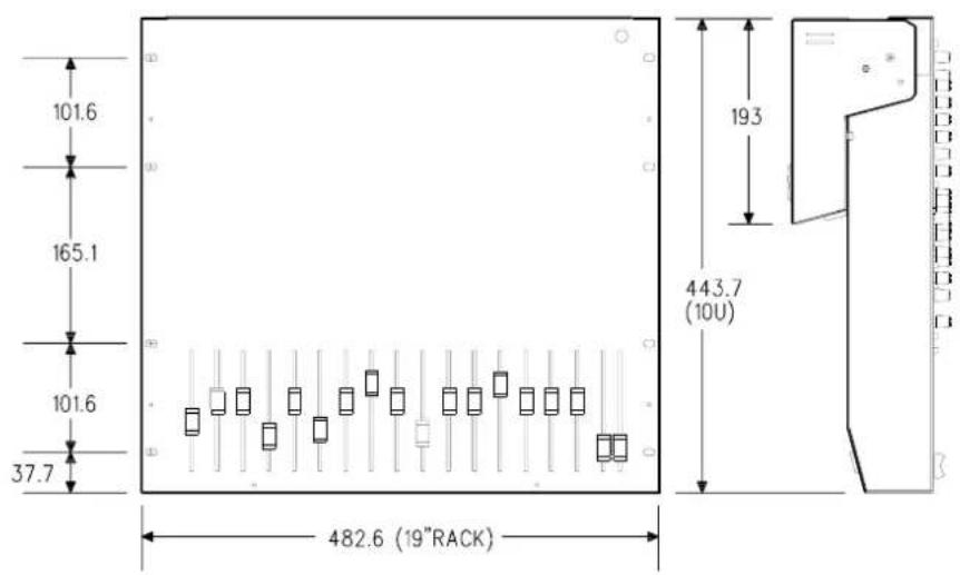
| Dimensions (Rack Mount) | 443.7 x 482.6 x ? mm (10U 19") |
| Weight | 11 kg (unpacked), 14 kg (packed) |
| Power Supply | Internal linear, 100-240V AC, 50/60Hz, 35W max |
| Input Channels | 10 mic/line (XLR & TRS), 2 stereo (RCA & TRS), 4 stereo returns |
| Outputs | L-R, Groups 1-4 (XLR), Mono (XLR), Aux 1-6 (TRS), 2-Track send (RCA), Phones (TRS) |
| EQ | 4-band with 2 swept mid bands (HF 12kHz, LF 60Hz, MF1 500Hz-15kHz, MF2 35Hz-1kHz) |
| Aux Sends | 6 (switchable pre/post, +6dB boost) |
| Group Routing | L-R, Groups 1-2, 3-4 with pan |
| Phantom Power | Individual for ch 1-4, global for ch 5-10 (+48V) |
| Special Features | QCC connector system, MSP (Minimum Signal Path), AUX/GROUP reverse |
| Meters | 12-segment LED bargraph for L/R, peak LEDs per channel |
| Talkback | XLR mic input with trim, talkback to aux 1-2/3-4/5-6 |
| Warranty | 1 year from purchase date (UK terms) |
| Cleaning | Soft brush and dry lint-free cloth; no chemicals or solvents |
| Safety | Must be earthed; use correct fuse (T630mA 100-120V, T315mA 220-240V) |
| Rear Panel | Connector pod can be repositioned for desktop or rack mounting |
Frequently Asked Questions - WZ14-4-2 ALLEN & HEATH
User questions about WZ14-4-2 ALLEN & HEATH
0 question about this device. Answer the ones you know or ask your own.
Ask a new question about this device
Download the instructions for your Blender in PDF format for free! Find your manual WZ14-4-2 - ALLEN & HEATH and take your electronic device back in hand. On this page are published all the documents necessary for the use of your device. WZ14-4-2 by ALLEN & HEATH.
USER MANUAL WZ14-4-2 ALLEN & HEATH
This product has been manufactured in the UK by ALLEN & HEATH and is warranted to be free from defects in materials or workmanship for period of one year from the date of purchase by the original owner.
To ensure a high level of performance and reliability for which this equipment has been designed and manufactured, read this User Guide before operating.
In the event of a failure, notify and return the defective unit to ALLEN & HEATH or its authorised agent as soon as possible for repair under warranty subject to the following conditions
CONDITIONS OF WARRANTY
- The equipment has been installed and operated in accordance with the instructions in this User Guide
- The equipment has not been subject to misuse either intended or accidental, neglect, or alteration other than as described in the User Guide or Service Manual, or approved by ALLEN & HEATH.
- Any necessary adjustment, alteration or repair has been carried out by ALLEN & HEATH or its authorised agent.
- The defective unit is to be returned carriage prepaid to ALLEN & HEATH or its authorised agent with proof of purchase.
- Units returned should be packed to avoid transit damage
These terms of warranty apply to UK sales. In other territories the terms may vary according to legal requirements. Check with your ALLEN & HEATH agent for any additional warranty which may apply.
WZ 14:4:2 User Guide AP3190 Issue 1. Copyright © 1997 Allen & Heath. All rights reserved

This product complies with the European Electromagnetic Compatibility Directives 89/336/EEC & 92/31EEC and the European Low Voltage Directives 73/23/EEC & 93/68EEC

MANUFACTURED IN ENGLAND
ALLEN & HEATH
Kernick Industrial Estate
Penryn, Cornwall, TR10 9LU. UK
http://www.allen-heath.com

A DIVISION OF HARMAN INTERNATIONAL INDUSTRIES Ltd
ALLEN & HEATH AGENT:
The WZ14:4:2 continues ALLEN & HEATH's commitment to provide high quality audio mixing consoles engineered to meet the exacting requirements of today's audio business. It brings you the latest in high performance technology and offers the reassurance of over two decades of console manufacture and customer support.
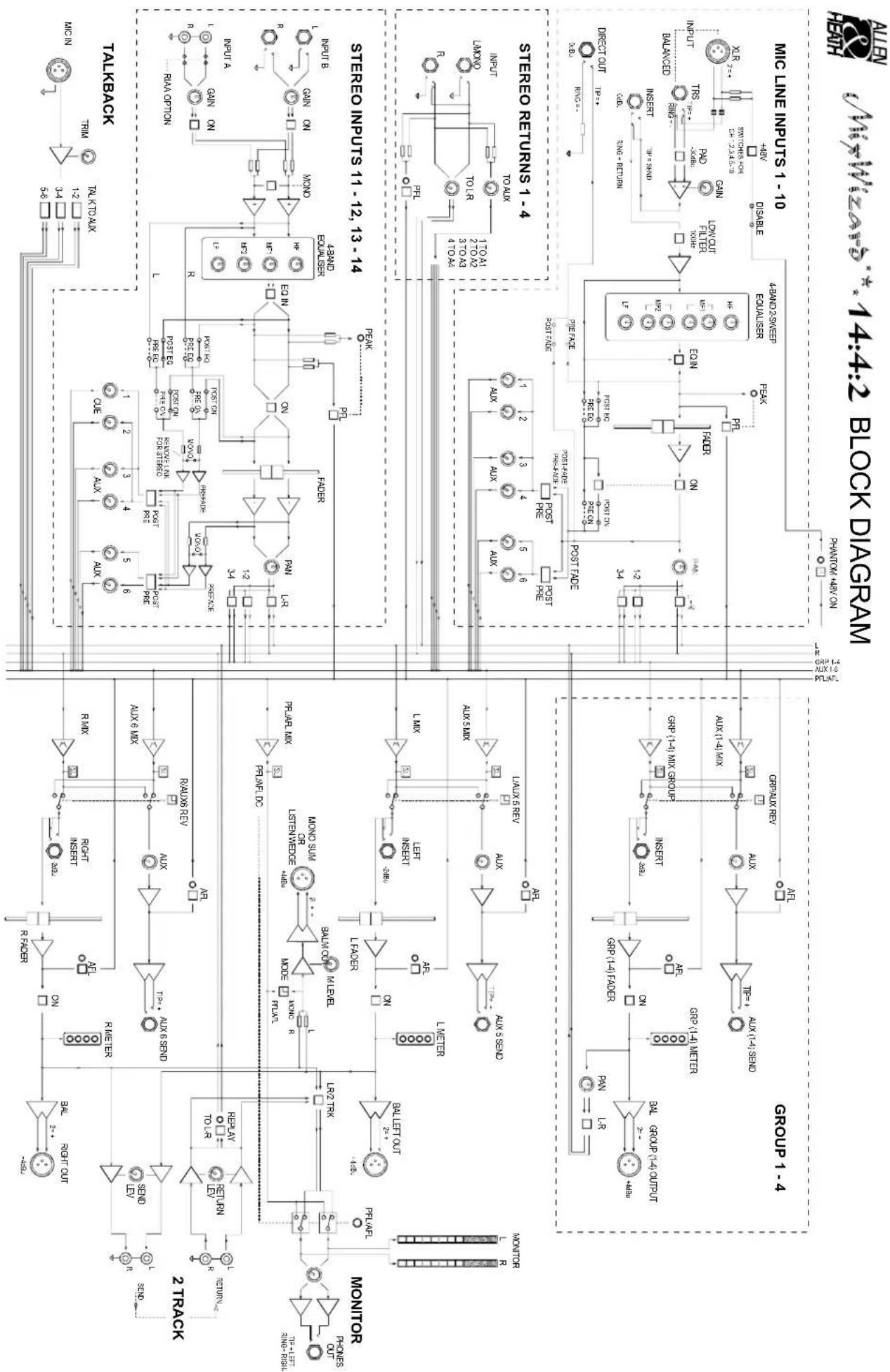
This user guide presents a quick reference to the function and application of the WZ14:4:2. We recommend that you read this guide fully before starting. For your convenience, the following pages contain information about applications, installing and connecting the console and its input and output sections. Front and rear panel drawings are included with a technical specification and a system block diagram is printed on the rear cover. For further information on the basic principles of audio system engineering, please refer to one of the specialist publications available from book shops and audio equipment dealers.
Whilst we believe the information in this guide to be reliable we do not assume responsibility for inaccuracies. We also reserve the right to make changes in the interest of further product development.
SERVICE AND TECHNICAL SUPPORT
We are able to offer further product support through our world-wide network of approved dealers and service agents. You can also access our Web site on the internet for information on our product range, assistance with your technical queries or simply to chat about matters audio... To help us provide the most efficient service please keep a record of the console serial number, and date and place of purchase to be quoted in any communication regarding this product.
SAFETY WARNING!
Mains electricity is dangerous and can kill. Mains voltage is present within the console.
Do not remove the covers with mains electricity connected. To ensure your safety, mains earth is connected to the chassis through the power lead. Do not remove this mains earth connection.
To avoid the risk of fire, replace the mains fuse only with the correct value and type as indicated on the connector panel.
GENERAL PRECAUTIONS
Your WZ14:4:2 is ruggedly constructed to withstand the rigours of the road whether location mixing or live gigging. However, you will extend the life of the console and preserve its cosmetics by applying these simple common sense precautions.
Prevent damage to the controls and cosmetics by avoiding drinks spillage, tobacco ash, smoke, and exposure to rain and moisture. If the console becomes wet switch off and remove mains power immediately. Allow to dry out thoroughly before using again.
Protect from excessive dirt, dust, heat and vibration when operating and storing.
Avoid the use of chemicals, abrasives or solvents. The control panel is best cleaned with a soft brush and dry lint-free cloth. The faders, switches and potentiometers are lubricated for life. The use of electrical lubricants on these parts is not recommended.
TRANSPORTING THE CONSOLE
The console may be transported as a free-standing unit or mounted in a rack or flightcase. Ensure that the connector pod is secured in place with the locking screws fitted to prevent movement. Use adequate packing if you need to ship the unit.
The WZ14:4:2 offers the professional user an uncompromised feature set with impressive performance for live sound engineering and recording. It is built on the established tradition of innovative British design and manufacture. The console is solidly reliable for a hard life on the road and uniquely versatile for any audio mixing application. The WZ14:4:2 is equally at home alongside top of the range live sound consoles such as the ALLEN & HEATH GL4000, in use in theatres, houses of worship, conference and club installations, home and recording studios, or multi-tasking with equipment hire companies. Check out the key features:
The Mix Wizard QCC (Quick Change Connector) system lets you quickly rotate the connectors for rear access desk top operation, or for underside access as required when mounted in a compact 10U 19" rack space.
MSP (Minimum signal path) for transparent audio is achieved by careful circuit design using high grade, low noise discrete and IC components aimed at providing the shortest signal path from input to output.
The 10 mic/line input channels each feature a 4 band EQ with 2 mid-sweep controls for source correction or enhancement equalisation, a 100Hz lo-cut filter, an EQ IN switch and individual phantom power switching on the rear panel for channels 1-4, global for channels 5-10, and a global on/off switch on the front panel. In addition, 6 auxiliary sends with up to 6dB of boost may be switched Pre/Post fader in groups 1-4 and 5-6. The input pre-amplifier provides a wide 70dB gain range for soft and loud signal sources. Cable matching is no longer a problem as each input offers both professional XLR and TRS jack sockets for any signal level, mic or line. A smooth action 100mm long travel fader with PAN control, ON switch, Pre Fade Listen (PFL) switch, L-R, & groups 1-2, 3-4 routing switches and PEAK (PFL) LED indicator complete the input channel. INSERTS for effects patching and DIRECT OUTPUTS for multitrack recording are also provided on the rear panel.
The 2 full facility stereo input channels feature dual inputs, A (RCA phonos) and B (jacks) each with individual gain control and on/off switching. A 4 band EQ with HF and LF shelving together with two fixed frequency peak/dip mid controls MF1 and MF2 providing 15dB of cut or boost.
A further 4 stereo returns ST1-4 each with feeds for AUX and L-R routing bring the total number of input connections up to 26.
The Master section includes 100mm GROUP and L-R master faders each with AFL, balanced XLR connectors on all outputs and INSERTS for signal processing. The MONO output is on balanced XLR with mode switching for either LR sum (mono) output or PFL/AFL for an engineer's listen wedge speaker. The groups also feature individual PAN controls with L-R and ON switches.
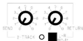
Above the groups, the AUX SEND master level controls provide an extra 10dB boost and AFL switches for monitoring. The GROUP/AUX reverse switch bank is located below the aux master section. Mode switching enables the user to reverse the aux outputs with the group outputs to configure the console for either FOH operation or on stage monitoring or both. This provides aux masters on balanced XLRs with inserts and fader control. The groups are redirected to the Aux master level controls and are on balanced TRS jacks. Individual mode switching for each Aux/Group is available permitting a wide variety of applications. Refer to the MODE SWITCHING section on page 15.
A headphone socket with level control is provided together with two 12 segment bargraph level meters for L & R signal monitoring.
2-Track recording and playback is set with the individual send and return level controls with routing for replay to the L-R mix. An XLR socket is provided for the talkback mic with a trim control for talkback to aux 1-2, 3-4, 5-6 in pairs.
A rugged all metal construction features individual circuit boards secured to the front panel via all rotary controls. No nonsense solid build ensures on the road reliability.
Live bands, Theatre, Church, Disco, Club, etc...
flowchart
graph TD
    A["MONO"] --> B["FOLDBACK"]
    B --> C["pre-fade aux sends"]
    C --> D["TWO TRACK RECORDER"]
    D --> E["EFFECTS PROCESSOR"]
    E --> F["TWO TRACK RECORDING AND INTERMISSION REPLAY"]
    F --> G["POST-FADER AUX SENDS"]
    G --> H["POST-FADER AUX"]
    H --> I["POST-FADER AUX"]
    I --> J["POST-FADER AUX"]
    J --> K["POST-FADER AUX"]
    K --> L["POST-FADER AUX"]
    L --> M["POST-FADER AUX"]
    M --> N["POST-FADER AUX"]
    N --> O["POST-FADER AUX"]
    O --> P["POST-FADER AUX"]
    P --> Q["POST-FADER AUX"]
    Q --> R["POST-FADER AUX"]
    R --> S["POST-FADER AUX"]
    S --> T["POST-FADER AUX"]
    T --> U["POST-FADER AUX"]
    U --> V["POST-FADER AUX"]
    V --> W["POST-FADER AUX"]
    W --> X["POST-FADER AUX"]
    X --> Y["POST-FADER AUX"]
    Y --> Z["POST-FADER AUX"]
    Z --> AA["POST-FADER AUX"]
    AA --> AB["POST-FADER AUX"]
    AB --> AC["POST-FADER AUX"]
    AC --> AD["POST-FADER AUX"]
    AD --> AE["POST-FADER AUX"]
    AE --> AF["POST-FADER AUX"]
    AF --> AG["POST-FADER AUX"]
    AG --> AH["POST-FADER AUX"]
    AH --> AI["POST-FADER AUX"]
    AI --> AJ["POST-FADER AUX"]
    AJ --> AK["POST-FADER AUX"]
    AK --> AL["POST-FADER AUX"]
    AL --> AM["POST-FADER AUX"]
    AM --> AN["POST-FADER AUX"]
    AN --> AO["POST-FADER AUX"]
    AO --> AP["POST-FADER AUX"]
    AP --> AQ["POST-FADER AUX"]
    AQ --> AR["POST-FADER AUX"]
    AR --> AS["POST-FADER AUX"]
    AS --> AT["POST-FADER AUX"]
    AT --> AU["POST-FADER AUX"]
    AU --> AV["POST-FADER AUX"]
    AV --> AW["POST-FADER AUX"]
    AW --> AX["POST-FADER AUX"]
    AX --> AY["POST-FADER AUX"]
    AY --> AZ["POST-FADER AUX"]
    AZ --> BA["POST-FADER AUX"]
    BA --> BB["POST-FADER AUX"]
    BB --> BC["POST-FADER AUX"]
    BC --> BD["POST-FADER AUX"]
    BD --> BE["POST-FADER AUX"]
    BE --> BF["POST-FADER AUX"]
    BF --> BG["POST-FADER AUX"]
    BG --> BH["POST-FADER AUX"]
    BH --> BI["POST-FADER AUX"]
    BI --> BJ["POST-FADER AUX"]
    BJ --> BK["POST-FADER AUX"]
    BK --> BL["POST-FADER AUX"]
    BL --> BM["POST-FADER AUX"]
    BM --> BN["POST-FADER AUX"]
    BN --> BO["POST-FADER AUX"]
    BO --> BP["POST-FADER AUX"]
    BP --> BQ["POST-FADER AUX"]
    BQ --> BR["POST-FADER AUX"]
    BR --> BS["POST-FADER AUX"]
    BS --> BT["POST-FADER AUX"]
    BT --> BU["POST-FADER AUX"]
    BU --> BV["POST-FADER AUX"]
    BV --> BW["POST-FADER AUX"]
    BW --> BX["POST-FADER AUX"]
    BX --> BY["POST-FADER AUX"]
    BY --> BZ["POST-FADER AUX"]
    BZ --> CA["POST-FADER AUX"]
    CA --> CB["POST-FADER AUX"]
    CB --> CC["POST-FADER AUX"]
    CC --> CD["POST-FADER AUX"]
    CD --> CE["POST-FADER AUX"]
    CE --> CF["POST-FADER AUX"]
    CF --> CG["POST-FADER AUX"]
    CG --> CH["POST-FADER AUX"]
    CH --> CI["POST-FADER AUX"]
    CI --> CJ["POST-FADER AUX"]
    CJ --> CK["POST-FADER AUX"]
    CK --> CL["POST-FADER AUX"]
    CL --> CM["POST-FADER AUX"]
    CM --> CN["POST-FADER AUX"]
    CN --> CO["POST-FADER AUX"]
    CO --> CP["POST-FADER AUX"]
    CP --> CQ["POST-FADER AUX"]
    CQ --> CR["POST-FADER AUX"]
    CR --> CS["POST-FADER AUX"]
    CS --> CT["POST-FADER AUX"]
    CT --> CU["POST-FADER AUX"]
    CU --> CV["POST-FADER AUX"]
    CV --> CW["POST-FADER AUX"]
    CW --> CX["TWO TRACK RECORDING AND INTERMISSION REPLAY"]
GRAPHIC EQUALISERS
Graphic equalisers are used to compensate for adverse room acoustics. These devices help reduce acoustic feedback and enhance the clarity of the sound.
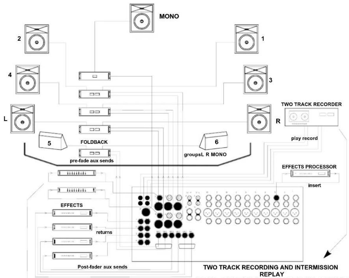
Use the console two track send and return sockets for connecting a cassette or DAT recorder. Alternatively, connect a CD player to the console two track return sockets for intermission replay. This does not affect the recording process.
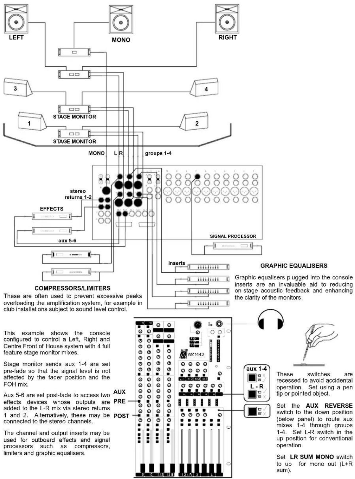
This example shows the 4 groups, L-R and Mono outputs feeding a 7 stack FOH amplification system. The groups provide independent control of the additional left and right loudspeaker stacks or may be used for zone feeds or for subgrouping to the L-R mix.
Select aux 1-4 post fade to access 4 effect processing devices. Use stereo returns 1-4 to add the effects to L-R and mono mix. Alternatively, return the effects to the stereo channels which allows fader control and EQ to be added.
Select aux 5-6 pre-fader for foldback monitor sends.
The channel and output inserts may be used for outboard effects and signal processing devices such as compressors, limiters and graphic equalisers.
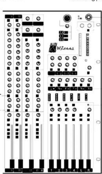

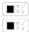
These switches are recessed to avoid accidental operation. Set using a pen tip or pointed object.
Set the AUX REVERSE switches to the up position for conventional aux/group operation
Set the LR SUM MONO switch to up for mono out (L+R sum)
On stage mixing system for local (side of stage) control of performers monitor loudspeakers (wedges) with dedicated output for monitor engineer's listen wedge.
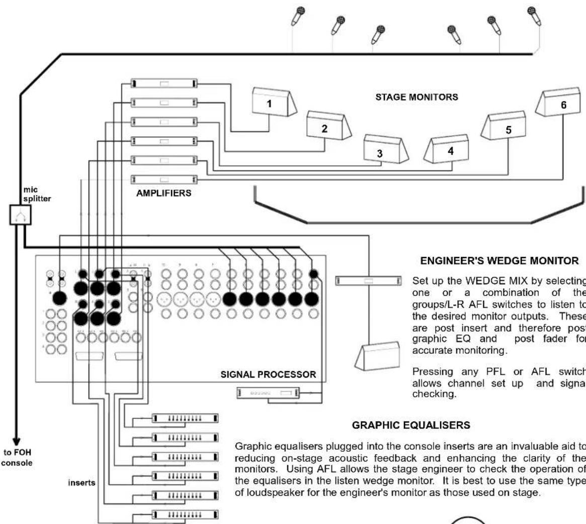
flowchart
graph TD
    A["STAGE MONITORS"] --> B["1"]
    A --> C["2"]
    A --> D["3"]
    A --> E["4"]
    A --> F["5"]
    A --> G["6"]
    H["AMPLIFIERS"] --> I["1"]
    H --> J["2"]
    H --> K["3"]
    H --> L["4"]
    H --> M["5"]
    N["SIGNAL PROCESSOR"] --> O["1"]
    N --> P["2"]
    N --> Q["3"]
    N --> R["4"]
    N --> S["5"]
    T["GENINEER'S WEDGE MONITOR"] --> U["Set up the WEDGE MIX by selecting one or a combination of the groups/L-R AFL switches to listen to the desired monitor outputs. These are post insert and therefore post graphic EQ and post fader for accurate monitoring. Pressing any PFL or AFL switch allows channel set up and signal checking."]
    V["GRAPHIC EQUALISERS"] --> W["Graphic equalisers plugged into the console inserts are an invaluable aid to reducing on-stage acoustic feedback and enhancing the clarity of the monitors. Using AFL allows the stage engineer to check the operation of the equalisers in the listen wedge monitor. It is best to use the same type of loudspeaker for the engineer's monitor as those used on stage."]
    X["to FOH console"] --> Y["inserts"]
This example shows the 6 aux sends routed through the main groups and L-R outputs to provide 6 independent stage monitor mixes with metering, ON/OFF switches, inserts and balanced XLR connectors.
The AUX/GROUP reverse switches reroute the group and L-R mix to the aux jacks outputs for additional monitoring or effect sends or as independent submix facilities. For example, aux 5 and 6 jack outputs may provide a separate stereo mix output from the channel L-R routing switches and the additional 4 stereo return line inputs.
Use the groups to add effects such as delay, reverb or echo to the stage monitors.
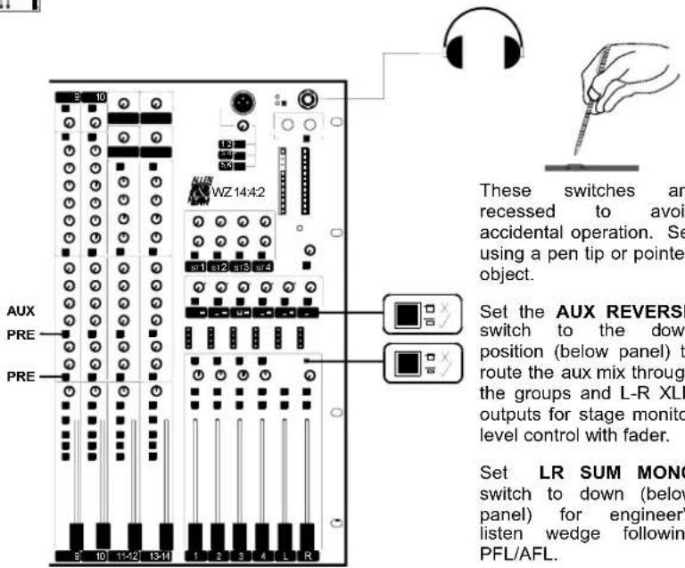
These switches are recessed to avoid accidental operation. Set using a pen tip or pointed object.
Set the AUX REVERSE switch to the down position (below panel) to route the aux mix through the groups and L-R XLR outputs for stage monitor level control with fader.
Set LR SUM MONO switch to down (below panel) for engineer's listen wedge following PFL/AFL.
Left, Centre and Right Front of house system with 4 dedicated stage monitor sends
The Mix Wizard Series features the ALLEN & HEATH Quick Change Connector (QCC) system. The rear connector pod may be hinged and locked into either of two positions: Rear connectors for desktop operation with the control panel sloped at a convenient 15 degrees, or underside connectors for 19" rack mounting in a compact 10U space. The connector position can be easily changed at any time to fit your application.
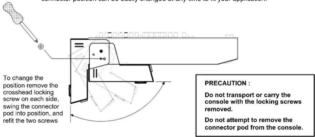
19" RACK MOUNTING
other
| Dimension | Value | | --------- | ----- | | Height | 101.6 | | Width | 165.1 | | Height | 37.7 | | Width | 193 | | Height | 443.7 (10U) | | Width | 482.6 (19" RACK) |Mount the console in the rack using 4x M6 bolts each side for maximum strength. We recommend you fit the bolts with plastic cup washers to protect the panel, and they look good... These should be available from the supplier of the rack unit or a good hardware store.
FLIGHTCASING
The console can be easily flightcased in either connector mode. Provide the dimensions shown here to your flightcase supplier.
DESKTOP OPERATION
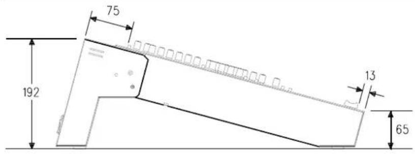
The console is fitted with rubber feet to ensure it does not slip or scratch the work surface. The control panel is angled at 15 degrees for operating convenience.
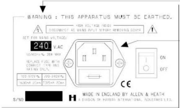
Refer to the SAFETY WARNING on page 3 of the User Guide. Check the voltage indicated on the rear panel is the same as the mains supply in your area. Check that the correct mains lead with moulded plug has been supplied with your console. Read and understand the warnings and instructions printed on the rear panel and reproduced here.
It is standard practice to turn connected power amplifiers down or off before switching the console on or off. Ensure that the IEC mains plug is pressed fully into the rear panel socket before switching on.
EARTHING

The connection to earth (ground) in an audio system is important for two reasons:
- SAFETY - To protect the operator from high voltage shock associated with the AC mains supply feeding the system, and
- AUDIO PERFORMANCE QUALITY - To minimise the effect of earth (ground) loops which result in audible hum and buzz, and to shield the audio signals from interference.
For safety it is important that all equipment earths are connected to mains earth so that exposed metal parts are prevented from carrying high voltage which can injure or even kill the operator. It is recommended that the sound engineer check the continuity of the safety earth from all points in the system including microphone bodies, guitar strings, multicore cases, equipment panels ...
The same earth is also used to shield audio cables from external interference such as the hum fields associated with power transformers, lighting dimmer buzz, and computer radiation. Problems arise when the signal sees more than one path to mains earth. An 'earth loop' (ground loop) results causing current to flow between the different earth paths. This condition is usually detected as a mains frequency audible hum or buzz.
To ensure safe and trouble-free operation we recommend the following:
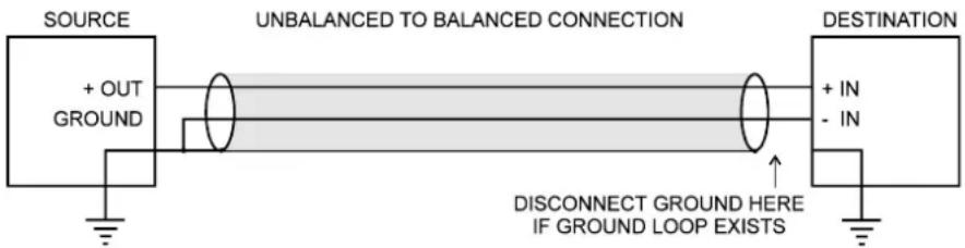
- Do not remove the earth connection from the console mains plug. The console chassis is connected to mains earth through the power cable to ensure your safety. Audio 0V is connected to the console chassis internally. If problems are encountered with earth loops operate the audio 'ground lift' switches on connected equipment accordingly, or disconnect the cable screens at one end, usually at the destination. It is useful to carry ground lift cable adapters such as short XLR male to female leads with pin 1 disconnected.
- Avoid running audio cables next to mains, computer or lighting cables, or near thyristor dimmer and power supply units. If unavoidable, cross these at right angles.
- Use low impedance sources such as microphones rated at 200 ohms or less to reduce susceptibility to interference. The console outputs are designed to operate at very low impedance to minimise interference problems.
- Use balanced connections where possible as these provide further immunity by cancelling out interference that may be picked up on long cable runs. To connect an unbalanced source to a balanced console input, link the cold input (XLR pin 3 or jack ring) to 0V earth (XLR pin 1 or jack sleeve) at the console. To connect a balanced console output to an unbalanced destination, link the cold output to 0V earth at the console.
- Use professional quality cables and connectors and check for correct wiring and reliable solder joints.
- If you are not sure ... Have your system checked by a competent engineer, or contact your local Allen & Heath agent for advice.
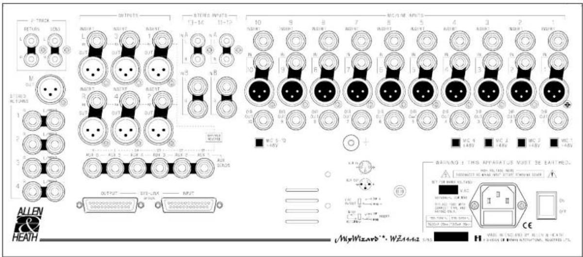
The Mix Wizard 14:4:2 uses professional grade 3-pin XLR, 1/4" TRS jack and RCA PHONO sockets. The applications diagrams on pages 5 to 7 illustrate typical equipment interconnections. To ensure best performance, we recommend that you use high quality audio cables and connectors, and take time to check for reliable and accurate cable assembly. It is well known that most audio system failures are due to faulty interconnecting leads.
CONNECTOR PINOUTS
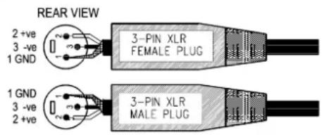
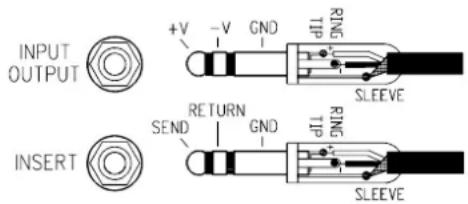
CONNECTORS, CABLES AND THEORY
All input and output XLR connectors are 3-wire differentially balanced. These have 3 connector pins: pin 1 = ground (cable screen), pin 2 = signal +ve, pin 3 = signal -ve
All the master output jack connectors are 3-wire balanced. These have 3 connector pins: tip = signal +ve, ring = signal -ve, sleeve = ground (cable screen).
Avoid reversing +ve and -ve on balanced connections as this will result in out of phase signals (reverse polarity) causing signal cancellation effects. This situation is particularly common in multi-microphone mixing.
For live work where long cables runs are required, balanced interconnections should be used. Short interconnections between more affordable 2-wire (signal, ground) unbalanced effects units or signal processors and mixing console may be utilised. Refer to the following diagram for unbalanced to balanced connections.
DEALING WITH GROUND LOOPS, BUZZ AND INTERFERENCE
For optimum performance all audio signals should be referenced to a solid, noise-free earth point, frequently referred to as the 'star point' or 'clean earth'.
A ground loop is created when the signal has more than one path to ground (earth). Should you experience hum or buzz caused by ground loops, check first that each piece of equipment has its own separate path to ground. If so, operate ground lift switches on connected equipment in accordance with the instruction manuals. Alternatively disconnect the cable screen at the destination end.
To avoid interference pickup keep audio cables away from mains power units and cables, thyristor dimmer units or computer equipment. Where this cannot be avoided, cross the cables at right angles to minimise interference.
CONNECTING CHANNEL INPUTS
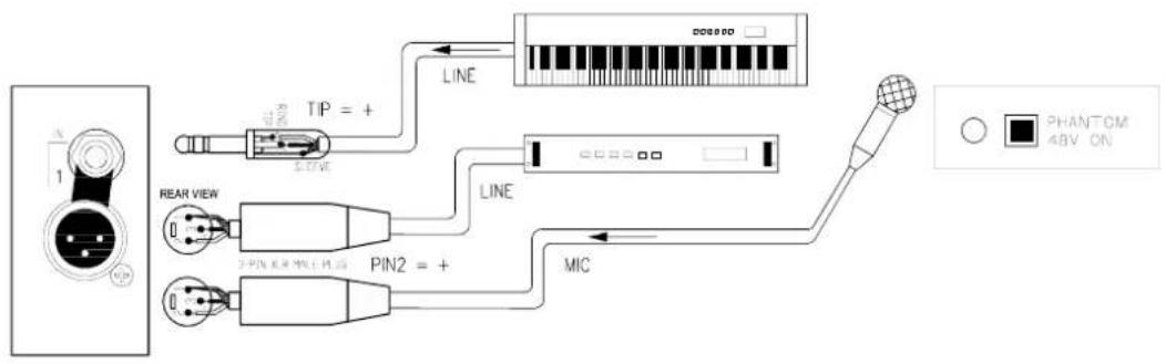
Both microphone and line sources such as keyboards, replay devices and effects processors can be plugged into either the jack or XLR input for convenience. Do not connect to both at the same time. The channel accepts a wide 70dB range of source levels. The balanced 3-wire input provides the best immunity to interference pickup on long cable runs.
CONNECTING CHANNEL INPUTS (CONT'D)
flowchart
graph TD
    A["Power Panel"] --> B["Resistor"]
    B --> C["TIP = +"]
    C --> D["Line"]
    D --> E["Microcontroller"]
    E --> F["Terminal Block"]
    G["REAR VIEW"] --> H["Pin2 = +"]
    I["0"] --> H
    J["0"] --> H
    H --> K["MIC"]
    L["PHANTOM 4BV ON"] --> M["Signal"]
CONNECTING TO CHANNEL INSERTS
You do not need to plug anything into the channel insert socket for normal operation. You may, however wish to insert a signal processor such as a compressor/limiter or noise gate into the channel signal path to prevent excessive peaks or to cut down source noise. The insert lets you do this by breaking the signal path after the input pre-amp and before the EQ. Use a Y-lead or suitable TRS jack lead to connect to the external processor. The insert operates at 0dBu line level. Adjust the processor input and output levels for optimum signal level.

flowchart
graph LR
    INSERT -->|SEND| TIP
    TIP -->|GND| RING
    RING --> SLV
    SLV -->|SEND| OUTPUT
    OUTPUT -->|INPUT| SOUT
    OUTPUT -->|EFFECT| INPUT
    INPUT -->|RETURN| SOUT
CHANNEL DIRECT OUTPUTS
The channel direct output taps the signal off post-fader (pre-fader if the internal link option is changed) for connection to external processing or recording equipment. This is ideal for multitrack recording during a live performance. Here each channel can be recorded on a separate track for mixdown later. The output is impedance balanced on TRS jack. This means that you get the benefit of interference immunity when connecting to outboard equipment with balanced inputs. You can, of course, also connect to unbalanced equipment. The signal operates at nominal 0dBu line level.
L-R MAIN OUTPUTS
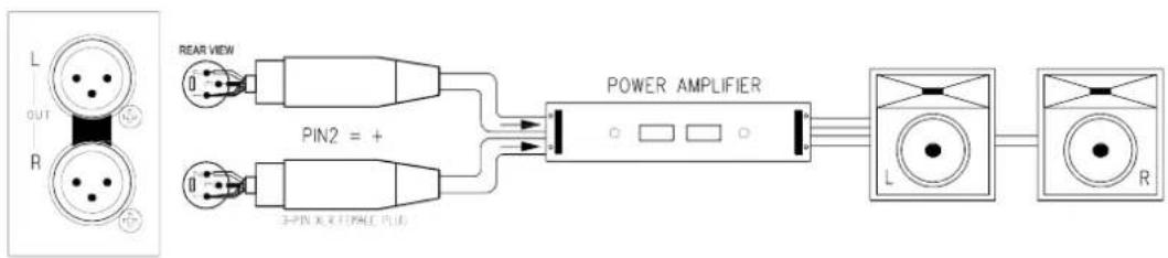
These 3-wire balanced outputs on XLR connectors operate at a nominal +4dBu to drive professional equipment over long cable runs without interference pickup. Connect to an amplifier, of suitable power rating for the venue, to drive the PA loudspeakers. Or connect to a 2-track recorder for studio or location recording.
L-R Mix INSERTS
Operation is identical to channel inserts. Use these sockets if you wish to insert external signal processing equipment into the mix pre-L-R fader. For live sound it is common to insert graphic equalisers to adjust for the room acoustics. Use a suitable Y-adapter lead as illustrated on page 11: tip = send, ring = return.
GROUPS
Groups 1-4 are output to 3-wire balanced XLR connectors to drive long cable runs. Inserts are provided as for the L-R outputs. Groups can be used to drive additional power amplifiers and speakers or for 4 track recording. If MODE SWITCHING aux/groups reverse is in operation, group faders are connected to the corresponding aux buss (Aux 1 to Group 1 fader, etc...). Refer to MODE SWITCHING section on page 15 for more information.
AUXILIARY SENDS
Auxiliaries 1-6 can be used to set up one or more stage monitor mixes or effects sends. Auxiliary outputs are on 1/4" TRS jacks.
Set up a pre-fade aux mix to send a stage monitor or cue mix to the performers. The aux outputs are 3-wire balanced for interference rejection when plugged into equipment with balanced inputs.
Set up a post-fade aux mix to send channel signals to an external effects device such as reverb or delay. Return the processed signal to the mix by plugging the device output into stereo returns 1-4, or into a stereo channel input. These inputs can operate balanced or unbalanced. For a mono return simply plug into the L input, leaving R unplugged. The setting of the channel aux send control combined with that of the fader position determines how much of the signal is sent to the aux master and subsequently to the effects unit.
If MODE SWITCHING aux/groups reverse is in operation, aux master level controls are connected to the corresponding group busses (Group 1 to Aux Master 1, etc...). Refer to MODE SWITCHING section on page 15 for more information.
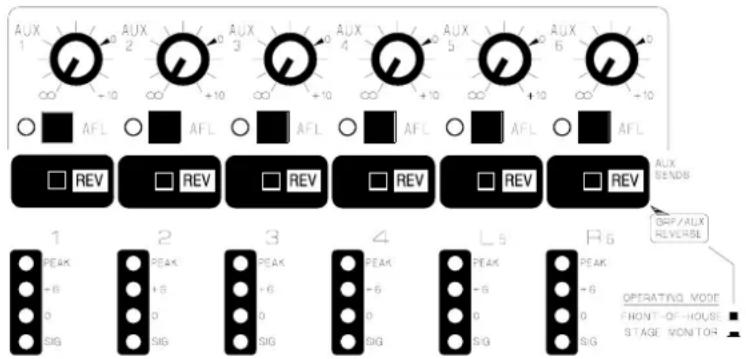
TWO TRACK RECORD AND REPLAY
Individual RCA phono sockets are provided for connecting a 2-Track stereo recorder such as a cassette or DAT machine. Connect the recorder input (REC) connections to the send sockets and the recorder output (PLAY) connectors to the return sockets.
The return can be switched to L-R mix for recording playback. The return can also be used for intermission replay from a CD player or similar playback device
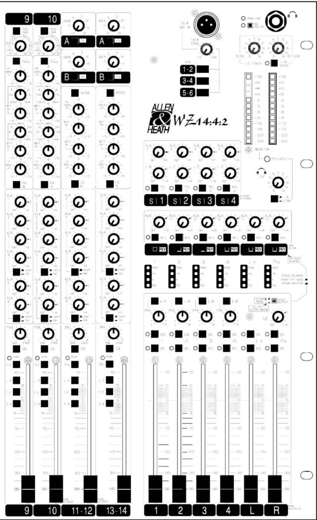
PAD - Attenuates the input signal by 30dB. It affects both the XLR and jack inputs. Press this switch when the input signal is too high with the GAIN control backed off.
GAIN - Use this control with the PAD switch to adjust the channel input sensitivity to match the connected source (-60 to +10dBu) to the console operating level (0dBu). Press the PFL switch to check that the signal reads an average '0' on the meters.
100Hz LO-CUT FILTER - Attenuates frequencies below 100Hz to reduce low frequency source noise such as microphone proximity popping, stage noise and transport rumble. It can also be used to clean up sounds which do not have much bass content, such as vocals and cymbals.
EQUALISER - This provides separate, simultaneous control of 4 frequency bands. Each band may boost or cut by up to +/- 15dB. The centre flat position is detented for quick resetting.
The HF and LF bands have a shelving response which means that all frequencies beyond the turning point frequency are affected, HF = 12kHz, LF = 60Hz. Use HF to add sparkle or to reduce source hiss. Use LF to add punch to the bass instruments. Used with the LO-CUT filter you can tailor the low frequency response exactly as you require.
The two swept mid frequency bands have a peak/dip (bell shaped) response which means that the maximum boost or cut occurs at the selected (centre) frequency. The centre frequency can be swept over a wide range. MF1 = 500Hz to 15kHz, MF2 = 35Hz to 1kHz. Use the mids to add warmth or presence to the sound or to notch out problem resonances which can result in feedback.
EQ IN - Press to switch the EQ into the signal path.
AUXILIARY SENDS - You can set up to 6 separately balanced mixes using the aux send controls. Up to +6dB of additional boost is available.
Aux 1 - 4 and Aux 5 - 6 can be used as either MONITOR SENDS to the performers or as EFFECTS SENDS to external signal processing equipment. The output can be monitored using the aux send master AFL system. MONITOR SENDS are normally set pre-fader (PRE) and EFFECTS SENDS normally post-fader (POST). When set to POST, the amount of channel signal in the monitor mix is dependent on the channel fader level. Pre-fade aux sends are post-EQ, post-ON as standard (can be reconfigured pre-EQ or pre-ON by setting internal links).
PAN - Positions the channel signal within the stereo image, L (odd groups) and R (even groups). The centre position (mono image) is detented for quick resetting.
ON - This turns the channel signal on or off.
PEAK - The red LED illuminates when the signal is within 5dB of clipping. Should this occur turn back the GAIN control to reduce the signal level. This LED also half illuminates when a PFL switch is pressed.
PFL - Press PFL (Pre Fade Listen) to listen to the pre-fade signal on headphones or local monitor without affecting the main outputs. The signal level is shown on the L and R bargraph meters.
L-R, 1-2, 3-4 ROUTING SWITCHES - These switches route the channel signal to L-R master and groups 1-2, 3-4. Use the pan control to route to individual groups, i.e. left to L, 1 or 3, or right to R, 2 or 4.
+48V PHANTOM POWER - This is switched individually for channels 1-4, global for channels 5-10 on the rear panel. Phantom power may be switched off altogether with global +48V switch located on the front panel near the headphone socket.
Channel fader - 100mm smooth action fader controls the overall channel level. All post fade aux send levels are dependent on the level of the channel fader.

DUAL INPUTS A & B - The stereo input channel features a dual input on RCA Phonos (A) and TRS jacks (B). This is ideal for fast switching between stereo sources without having to repatch the console or mixing two stereo sources together.
GAIN A - Use this control to adjust the channel input sensitivity to match the connected source (-20 to +10dBu) to the console operating level (0dBu) on the RCA Phono connectors. Press PFL to check the signal reads an average of '0' on the meters.
ON A - Selects stereo source A (RCA PHONOS)
GAIN B - Use this control to adjust the channel input sensitivity to match the connected source (-20 to +10dBu) to the console operating level (0dBu) on the TRS Jack connectors. Press PFL to check the signal reads an average of '0' on the meters.
ON B - Selects stereo source B (TRS JACKS). Press both A and B to mix both sources together.
MONO - Combines the left and right outputs to mono the source. May also be used to input a mono source to the stereo channel path.
EQUALISER - Shelving HF and LF and two fixed frequency peak/dip mid controls provide 15dB of boost or cut. The mid frequency controls provide optimum control over boomy or boxy sounds and to add bite or reduce harshness of keyboards, vocals, etc. Use the mids to add warmth or presence to the sound.
EQ IN - Press to switch the EQ into the signal path.
AUXILIARY SENDS - You can set up to 6 separately balanced mixes using the aux send controls. Up to +6dB of boost is available.
Aux 1-4 and Aux 5-6 can be used as either MONITOR SENDS to the performers or as EFFECTS SENDS to external signal processing equipment. The output can be listened to using the aux master AFL system. MONITOR SENDS are normally set pre-fader (PRE) and EFFECTS SENDS normally post-fader (POST). When set to POST, the amount of channel signal in the monitor mix is dependent on the channel fader level. Pre-fade aux sends are post-EQ, post-ON as standard (can be reconfigured pre-EQ or pre-ON by setting internal links).
The Left and Right stereo signals are summed to provide aux feeds in mono. However internal link options allow for pre or post aux sends as stereo pairs i.e. AUX 1 = left, AUX 2 = right, etc. Refer to the options section in this user guide.
BAL - Balances the channel signal within the stereo image, L (odd groups) and R (even groups). The centre position is detented for quick resetting.
ON - This turns the channel signal on or off.
PEAK - The red LED illuminates when the signal is within 5dB of clipping. Should this occur turn back the GAIN control to reduce the signal level. This LED also half illuminates when a PFL switch is pressed.
PFL - Press PFL to listen to the pre-fade signal (mono) on headphones or local monitor without affecting the main outputs. The signal level is shown on the L and R bargraph meters.
L-R, 1-2, 3-4 ROUTING SWITCHES - These switches route the channel signal to L-R master, groups 1-2, 3-4. Use the BAL control to route to individual groups or to adjust the balance between the left and right signals.
Channel fader - 100mm smooth action fader controls the overall channel level. All post fade aux send levels are dependent on the level of the channel fader.
GROUPS
Group outputs are controlled by 100mm travel faders which offer a further 10dB boost above the normal '0' dB operating level. ON switches the group output on or off.
AFL (After Fade Listen) routes the post fader signal to the console meters and headphone monitoring to allow checks for sound quality and mix level. The AFL signal is sourced before the ON switch allowing the signal to be checked even when the group is switched off.
Each group has a 4 segment LED peak reading meter providing signal presence indication and peak warning which illuminates approximately 5dB before clipping.
SUB GROUPING
Sometimes it is necessary to control more than one channel simultaneously, in the case of a drum kit or a group of backing vocalists for example. Route the relevant channels to groups instead of L-R, using the channel group routing switches and the pan controls. The PAN control positions the signal in the stereo image with the L-R switch routing the group output to the Left & Right masters. Ensure the group L-R switch is "in" to route the group output to the L-R masters. In this way, the level of several channels can be controlled by one group fader. It is possible to set up mono or stereo subgroups using the channel and group PAN controls.
Aux Masters
Each aux mix has a master level control that adjusts the output level to match external equipment, or to trim the monitor or effects level without affecting the mix balance. Up to +10dB of boost is available above the nominal '0' position.
MODE SWITCHING
The Mix Wizard 14:4:2 features a bank of group GROUP/AUX REVERSE (REV) switches, one for each aux bus located under aux send masters 1-6. These switches are recessed to avoid accidental operation. Set using a pointed object or a pen tip.
This feature allows you to set the operation of the console for Front Of House, Stage monitor or a combination of both. With the switches out, the groups operate in the conventional manner, channel routing being possible with the group routing switches. When the REV switches are pressed in, the group busses are routed to the AUX send masters and the aux busses are routed to the GROUPS (Aux 1 to Group 1, etc). Aux 5 & 6 are routed to L-R faders respectively. This configuration allows the user to control up to six monitor mixes with the convenience of controlling levels on faders. Outputs are on balanced XLRs for long cable runs and a signal processor (equaliser, compressor, limiter, etc.) can be inserted into the signal path using the group and left/right insert jacks.
The channel L-R and group busses are still operational but are now routed to aux master controls and can be used for additional monitor or effect sends.
It is advisable to study the Mix Wizard 14:4:2 block diagram to fully understand this flexible routing arrangement.
An example of an application using a combined configuration could be as follows: Route submix channels 1-6 (drum kit) to groups 1 & 2. GROUPS 1 & 2 panned left & right respectively and routed to L-R. AUX 3-4 set prefade (PRE) and aux send masters reversed with groups 3-4 for stage monitor sends. Other channels routed to L-R mix as normal. Aux 5-6 set post fader (POST) for effect sends. This shows the versatility of the Mix Wizard 14:4:2. See DUAL MODE application diagram on page 7.


MAIN L-R OUTPUTS
L-R FADERS - Individual 100mm faders adjust the main L-R mix level with +10dB boost available above the nominal '0' position. For best performance the faders should be operated around the '0' position for normal 'loud' level. If you find yourself operating significantly below '0' then the amplifier or recorder input is too sensitive for the console +4dBu output. Simply turn down the amplifier or recorder level trim. If none is available then insert an attenuator pad between the console and connected equipment.
Mono Output
MONO - Sums L+R mix to produce a mono signal. Output is on a balanced XLR for long cable runs. A MODE SWITCH allows the signal to be switched from the mono sum to AFL/PFL. This switch is recessed to avoid accidental operation. Use a pointed object or pen tip to operate.
When switched to L-R MONO SUM, the MONO output provides for a centre fill or sub-bass loudspeaker, mono recording or broadcast feed. When switched to AFL/PFL, you can feed a stage monitor engineer's listen wedge.
STEREO RETURNS
Four stereo returns ST1 - 4 are provided giving you a total of 26 inputs to the L-R mix. These are normally used for returning the processed signal from effects devices. They can also be used for additional submix inputs.
The AUX control feeds the summed left and right signal to the corresponding aux bus. This is ideal for returning effects to the monitors without using up valuable channel inputs. The L-R level control feeds the stereo signal to the L-R mix.
PHONES MONITOR AND BARGRAPH METERS
Use stereo headphones with a nominal impedance of 30 to 600 ohms. Adjust the LEV control for a comfortable listening level. The phones and the 12 segment bargraph normally meter the post fade L-R mix or the two track return depending on the position of the L-R/2TRK switch. Pressing any AFL/PFL button on the console will override the monitor with the selected AFL/PFL signal. A large red LED located below the meters indicates when a PFL/AFL switch has been pressed when illuminated.
TALKBACK
An XLR Talkback mic socket is provided on the front panel for connecting a standard low impedance dynamic microphone. Talkback buttons 1-2, 3-4, 5-6 send the talkback signal to the corresponding aux busses. Press and hold these buttons for talkback. The TALK TRIM controls the talkback mic input level.
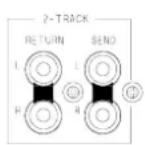
TWO TRACK SEND AND RETURN
The two track send and return controls are provided for a stereo recorder such as a cassette or DAT machine. The SEND may be used for recording the performance in stereo or to drive an induction loop hearing aid system. The send outputs are post L-R fader as standard. Press L-R REPLAY to route the replay signal to the L-R mix. Separate send and return level controls adjust the signal to the required level and sensitivity. The console can work with both high (+4dBu) and low (-10dBV) level equipment.
SPECIFICATIONS
0 dBu = 0.775 Volts rms 0 dBV = 1 Volt rms
HEADROOM:....+21dB channels ....+23dB mix to output
MAX OUTPUT: Balanced .....+25dBu 2kohm max load Unbalanced ....+21dBu 2kohm max load
METERS: L, R.....peak reading 12 bar LED
PEAK LEDs: .... Turn on 5dB before clipping
FREQUENCY RESPONSE: 20Hz to 50kHz +0/-1dB
DISTORTION: THD+Noise at +14dBu 1kHz Channel to mix output .... 0.006%
WEIGHT: unpacked 11kg, packed 14kg
CROSSTALK: Referred to driven channel at 1kHz Channel fader off ....- <-90dB Channel off ....- <-90dB
NOISE: Measured rms 22Hz to 22kHz bandwidth Mic input EIN (150 ohm source) ....- <-128dB LR output residual noise....<-97dBu (101dBS/N) LR faders unity mix noise ....- <-87dBu (-91dB S/N)
POWER SUPPLY: internal, linear regulated AC Mains input: .... IEC socket with lead supplied ....100 to 240V AC @ 50/60Hz ....factory wired to country voltage Power consumption: .... 35W max Mains Fuse rating: .... 100-120V AC T630mA 20mm ....220-240V AC T315mA 20mm
CONNECTIONS
INPUTS:
| Channel 1-10 in.... | XLR.... | pin 2 hot, 3 cold, bal.... | PAD out.... | 2k ohm variable -60 to -20dBu |
| TRS jack.... | tip hot, ring cold, bal.... | PAD in.... | >10k ohm variable -30 to +10dBu | |
| Stereo 11/12-13/14 in.. | TRS jack (L/M,R).... | tip sig, ring gnd, unbal.... | >10k ohm.... | -20 to +10dBu |
| RCA PHONO.... | unbalanced.... | >10k ohm.... | -20 to +10dBu | |
| Stereo return.... | TRS jack.... | tip sig, ring gnd, unbalanced .... | >10k ohm.... | -10dBV minimum |
| 2-Track return.... | RCA PHONO.... | unbalanced.... | >10k ohm.... | variable -10dBV minimum |
| Talkback mic in.... | XLR.... | pin 2 hot, 1 cold, unbalanced .... | 2k ohm.... | variable -40 to -15dBu |
INSERTS:
| Channel 1-10 Insert.... TRS jack.... tip send, ring return, unbal....<75 ohm, >3k ohm | 0dBu |
| L-R mix/groups.... TRS jack.... tip send, ring return, unbal....<75 ohm, >7k ohm | -2dBu |
OUTPUTS:
| L,R/Groups out......XLR......pin 2 hot, 3 cold, balanced ....<75 ohm......+4dBu | |
| Mono out......XLR......pin 2 hot, 3 cold, balanced ....<75 ohm......+4dBu | |
| Aux 1-6 out......TRS jack......tip hot, ring cold, balanced ....<75 ohm......+4dBu | |
| 2-Track send......RCA PHONO......unbalanced....<75 ohm......variable -10dBV minimum | |
| Phones out......TRS jack......tip left, ring right......for stereo headphones 30 to 600 ohms | |
| Channel direct out......TRS jack......tip hot, ring cold, impedance balanced..<75 ohm......0dBu |
The Mix Wizard Series WZ14:4:2 has a versatile architecture designed to satisfy your live sound and recording requirements without modification. The following internal options are offered to provide alternative settings for those applications which may demand them. These options require resoldering of circuit board links and should only be carried out by competent technical personnel. Further information is available from your service agent or the WZ14:4:2 SERVICE MANUAL.
CHANNEL PRE-FADE AUX SEND OPTIONS
The Pre-fade aux sends are set post-EQ and post-ON as standard. However, link options on each mic/line channel 1-10 and stereo channels 11-12 and 13-14 circuit board assemblies allow pre-EQ and/or pre-ON if required.
STEREO CHANNEL AUX SENDS
The stereo input channels allow stereo input signals to feed the auxiliaries as stereo pairs. By removing a link the left input signal will feed AUX 1, 3, 5, and the right input signal will feed AUX 2, 4, 6.
CHANNEL DIRECT OUTPUT SOURCE
The direct outputs are sourced post-fader as standard. A link option is available on each channel assembly to select a pre-fade source.
SYS-LINK™ OPTION
The SYS-LINK™ option is an internally fitted circuit board and wiring harness which can easily be installed by your service agent. The SYS-LINK™ option allows up to five ALLEN & HEATH consoles to be electronically connected together via a 25 pin D type multiway interconnecting cable to provide more inputs to the mix.
RIAA OPTION
An RIAA PCB assembly plus earth post can be fitted to input A of each of the two stereo input channels to allow connection for a turntable. Contact your dealer or service agent.
flowchart
graph TD
    subgraph Group 1 - 4
        A["MONITOR"] --> B["MONITOR"]
        B --> C["PROBNERS OUT"]
        C --> D["2 TRACK"]
        D --> E["SPEND"]
        E --> F["RS/RAV"]
        F --> G["REFL/RN"]
        G --> H["TO LTR"]
        H --> I["REFL/RN"]
        I --> J["TO LTR"]
        J --> K["REFL/RN"]
        K --> L["REFL/RN"]
        L --> M["REFL/RN"]
        M --> N["REFL/RN"]
        N --> O["REFL/RN"]
        O --> P["REFL/RN"]
        P --> Q["REFL/RN"]
        Q --> R["REFL/RN"]
        R --> S["REFL/RN"]
        S --> T["REFL/RN"]
        T --> U["REFL/RN"]
        U --> V["REFL/RN"]
        V --> W["REFL/RN"]
        W --> X["REFL/RN"]
        X --> Y["REFL/RN"]
        Y --> Z["REFL/RN"]
        Z --> AA["REFL/RN"]
        AA --> AB["REFL/RN"]
        AB --> AC["REFL/RN"]
        AC --> AD["REFL/RN"]
        AD --> AE["REFL/RN"]
        AE --> AF["REFL/RN"]
        AF --> AG["REFL/RN"]
        AG --> AH["REFL/RN"]
        AH --> AI["REFL/RN"]
        AI --> AJ["REFL/RN"]
        AJ --> AK["REFL/RN"]
        AK --> AL["REFL/RN"]
        AL --> AM["REFL/RN"]
        AM --> AN["REFL/RN"]
        AN --> AO["REFL/RN"]
        AO --> AP["REFL/RN"]
        AP --> AQ["REFL/RN"]
        AQ --> AR["REFL/RN"]
        AR --> AS["REFL/RN"]
        AS --> AT["REFL/RN"]
        AT --> AU["REFL/RN"]
        AU --> AV["REFL/RN"]
        AV --> AW["REFL/RN"]
        AW --> AX["REFL/RN"]
        AX --> AY["REFL/RN"]
        AY --> AZ["REFL/RN"]
        AZ --> BA["REFL/RN"]
        BA --> BB["REFL/RN"]
        BB --> BC["REFL/RN"]
        BC --> BD["REFL/RN"]
        BD --> BE["REFL/RN"]
        BE --> BF["REFL/RN"]
        BF --> BG["REFL/RN"]
        BG --> BH["REFL/RN"]
        BH --> BI["REFL/RN"]
        BI --> BJ["REFL/RN"]
        BJ --> BK["REFL/RN"]
        BK --> BL["REFL/RN"]
        BL --> BM["REFL/RN"]
        BM --> BN["REFL/RN"]
        BN --> BO["REFL/RN"]
        BO --> BP["REFL/RN"]
        BP --> BQ["REFL/RN"]
        BQ --> BR["REFL/RN"]
        BR --> BS["REFL/RN"]
        BS --> BT["REFL/RN"]
        BT --> BU["REFL/RN"]
        BU --> BV["REFL/RN"]
        BV --> BW["REFL/RN"]
        BW --> BX["REFL/RN"]
        BX --> BY["REFL/RN"]
        BY --> BZ["REFL/RN"]
        BZ --> CA["REFL/RN"]
        CA --> CB["REFL/RN"]
        CB --> CC["REFL/RN"]
        CC --> CD["REFL/RN"]
        CD --> CE["REFL/RN"]
        CE --> CF["REFL/RN"]
        CF --> CG["REFL/RN"]
        CG --> CH["REFL/RN"]
        CH --> CI["REFL/RN"]
        CI --> CJ["REFL/RN"]
        CJ --> CK["REFL/RN"]
        CK --> CL["REFL/RN"]
        CL --> CM["REFL/RN"]
        CM --> CN["REFL/RN"]
        CN --> COB["REFL/RN"]
        COB --> CPB["XTR"]
    end

    subgraph Group 1 - 4
        D["MIC LINE INPUTS 1 - 10"] --> E["MIC LINE INPUTS 1 - 10 + 10 + 10 + 10 + 10 + 10 + 10 + 10 + 10 + 10 + 10 + 10 + 10 + 10 + 10 + 10 + 10 + 10 + 10 + 10 + 10 + 10 + 10 + 10 + 10 + 10<br>    end<br><br>    subgraph Group 1 - 4<br>        E[MIC LINE INPUTS 1 - 10"] --> F["MIC LINE INPUTS 1 - 10 + 10 + 10 + 10 + 10 + 10 + 10 + 10 + 10 + 10 + 10 + 10 + 10 + 10<br>    end<br><br>    subgraph Group 1 - 4<br>        F[MIC LINE INPUTS 1 - 10"] --> G["MIC LINE INPUTS 1 - 10 + 10 + 10 + 10 + 10 + 10 + 10 + 10 + 10 + 10 + 10 + 10<br>    end<br><br>    subgraph Group 1 - 4<br>        G[MIC LINE INPUTS 1 - 10"] --> H["MIC LINE INPUTS 1 - 10 + 10 + 10 + 10 + 10 + 10 + 10 + 10 + 10 + 10<br>    end<br><br>    subgraph Group 1 - 4<br>        H[MIC LINE INPUTS 1 - 10"] --> I["MIC LINE INPUTS 1 - 10 + 10 + 10 + 10 + 10 + 10 + 10 + 10 + 10<br>    end<br><br>    subgraph Group 1 - 4<br>        I[MIC LINE INPUTS 1 - 10"] --> J["MIC LINE INPUTS 1 - 10 + 10 + 10 + 10 + 10 + 10 + 10 + 10 + 10<br>    end<br><br>    subgraph Group 1 - 4<br>        J[MIC LINE INPUTS 1 - 10"] --> K["MIC LINE INPUTS 1 - 10 + 10 + 10 + 10 + 10 + 10 + 10 + 10 + 10<br>    end<br><br>    subgraph Group 1 - 4<br>        K[MIC LINE INPUTS 1 - 10"] --> L["MIC LINE INPUTS 1 - 10 + 10 + 10 + 10 + 10 + 10 + 10 + 10 + 10<br>    end<br><br>    subgraph Group 1 - 4<br>        L[MIC LINE INPUTS 1 - 10"] --> M["MIC LINE INPUTS 1 - 10 + 10 + 10 + 10 + 10 + 10 + 10 + 10 + 10<br>    end<br><br>    subgraph Group 1 - 4<br>        M[MIC LINE INPUTS 1 - 10"] --> N["MIC LINE INPUTS 1 - 10 + 10 + 10 + 10 + 10 + 10 + 10 + 10<br>    end<br><br>    subgraph Group 1 - 4<br>        N[MIC LINE INPUTS 1 - 10"] --> O["MIC LINE INPUTS 1 - 10 + 9.56738888888888888888888888888888888888888888888888888888888888888888888888888888888888888888888888888888<br>    end<br><br>    subgraph Group 1 - 4<br>        O[MIC LINE INPUTS 1 - 9.567336666666666666666666666666666666666666666666666666666666666666666666666666666666666666666666666666666<br>    end<br><br>    subgraph Group_4<br>        P[MIC LINE INPUTS"] --> Q["MIC LINE INPUTS"] & R["MIC LINE INPUTS"] & S["MIC LINE INPUTS"] & T["MIC LINE INPUTS"] & U["MIC LINE INPUTS"] & V["MIC LINE INPUTS"] & W["MIC LINE INPUTS"] & X["MIC LINE INPUTS"] & Y["MIC LINE INPUTS"] & Z["MIC LINE INPUTS"] & AA["MIC LINE INPUTS"] & AB["MIC LINE INPUTS"] & AC["MIC LINE INPUTS"] & AD["MIC LINE INPUTS"] & AE["MIC LINE INPUTS"] & AF["MIC LINE INPUTS"] & AG["MIC LINE INPUTS"] & AH["MIC LINE INPUTS"] & AI["MIC LINE INPUTS"] & AJ["MIC LINE INPUTS"] & AK["MIC LINE INPUTS"] & AL["MIC LINE INPUTS"] & AM["MIC LINE INPUTS"] & AN["MIC LINE INPUTS"] & AO["MIC LINE INPUTS"] & AP["MIC LINE INPUTS"] & AQ["MIC LINE INPUTS"] & AR["MIC LINE INPUTS"] & AS["MIC LINE INPUTS"] & AT["MIC LINE INPUTS"] & AU["MIC LINE INPUTS"] & AV["MIC LINE INPUTS"] & AW["MIC LINE INPUTS"] & AX["MIC LINE INPUTS"] & AY["MIC LINE INPUTS"] & AZ["MIC LINE INPUTS"] & BA["MIC LINE INPUTS"] & BB["MIC LINE INPUTS"] & BC["MIC LINE INPUTS"] & DA["MIC LINE INPUTS"] & AE["MIC LINE INPUTS"] & AF["MIC LINE INPUTS"] & AG["MIC LINE INPUTS"] & AH["Mic Line Inputs"]
- CONDITIONS OF WARRANTY
- MANUFACTURED IN ENGLAND
- ALLEN & HEATH AGENT:
- SERVICE AND TECHNICAL SUPPORT
- SAFETY WARNING!
- GENERAL PRECAUTIONS
- TRANSPORTING THE CONSOLE
- FLIGHTCASING
- EARTHING
- CONNECTOR PINOUTS
- CONNECTORS, CABLES AND THEORY
- DEALING WITH GROUND LOOPS, BUZZ AND INTERFERENCE
- CONNECTING CHANNEL INPUTS
- CONNECTING TO CHANNEL INSERTS
- CHANNEL DIRECT OUTPUTS
- L-R MAIN OUTPUTS
- L-R Mix INSERTS
- GROUPS
- AUXILIARY SENDS
- TWO TRACK RECORD AND REPLAY
- SUB GROUPING
- Aux Masters
- MODE SWITCHING
- MAIN L-R OUTPUTS
- Mono Output
- STEREO RETURNS
- PHONES MONITOR AND BARGRAPH METERS
- TALKBACK
- TWO TRACK SEND AND RETURN
- SPECIFICATIONS
- CONNECTIONS
- INPUTS:
- INSERTS:
- OUTPUTS:
- CHANNEL PRE-FADE AUX SEND OPTIONS
- STEREO CHANNEL AUX SENDS
- CHANNEL DIRECT OUTPUT SOURCE
- SYS-LINK™ OPTION
- RIAA OPTION
Brand : ALLEN & HEATH
Model : WZ14-4-2
Category : Blender