
SQ-5 - Blender ALLEN & HEATH - Free user manual and instructions
Find the device manual for free SQ-5 ALLEN & HEATH in PDF.


| Product Type | Digital Mixing Console |
| Brand | Allen & Heath |
| Model | SQ-5 |
| Category | Audio Mixer |
| Input Channels | 48 (32 mono + 2 stereo) |
| Mixing Buses | 36 (12 aux, 8 FX, 4 matrix, 1 LR, 1 mono) |
| Built-in Effects | 8 stereo FX engines (reverb, delay, modulation, etc.) |
| Touchscreen | 7-inch capacitive color touchscreen |
| USB Audio | 32x32 USB 2.0 audio interface |
| Faders | 12 motorized faders with 4 layers (48 channels total) |
| Dimensions (W x D x H) | 514 x 518 x 210 mm |
| Weight | 12.7 kg (28 lbs) |
| Power Supply | 100-240V AC, 50/60 Hz, 150W max |
| Construction | Steel chassis with aluminum side panels |
| Cooling | Fan cooled, variable speed |
| Connectivity | 2x Ethernet (ACE, dSNAKE), 1x USB-B, 1x USB-A, 2x XLR (L/R out), 1x headphone |
| Operating System | Allen & Heath firmware (FPGA-based) |
| Rackmountable | Yes (optional rack ears) |
| Sample Rate | 48 kHz / 96 kHz |
| Latency | 0.7 ms (at 96 kHz) |
| Maintenance | Keep vents clean, use dry cloth for cleaning |
| Safety | Class I equipment, earth connection required |
| Spare Parts & Repairability | Authorized service centers only; faders, power supply replaceable |
Frequently Asked Questions - SQ-5 ALLEN & HEATH
User questions about SQ-5 ALLEN & HEATH
0 question about this device. Answer the ones you know or ask your own.
Ask a new question about this device
Download the instructions for your Blender in PDF format for free! Find your manual SQ-5 - ALLEN & HEATH and take your electronic device back in hand. On this page are published all the documents necessary for the use of your device. SQ-5 by ALLEN & HEATH.
USER MANUAL SQ-5 ALLEN & HEATH
4.1 Physical Controls....9
4.2 Channel Types....10
4.3 On-screen Parameters, Menus and Pop-ups .....10
4.4 On-screen Title bar....11
4.5 Home Screen 12
4.6 Diagnostics....12
4.7 Basic Workflow Concepts....13
4.8 SQ-Rack Screens....14
4.9 Screens Reference....19
- Connections....21
5.1 Local Inputs....21
5.2 Local Outputs 21
5.3 SLink 22
5.4 USB....22
5.5 Network 22
5.6 I/O Port....22
5.7 Footswitch....22
- I/O Patching....23
6.1 Patching 23
6.2 Local Sockets....25
6.3 SLink Sockets....25
6.4 ME Systems 26
6.5 USB-B and SQ-Drive Channels....26
6.6 I/O Port Channels....26
6.7 Tie Lines....27
6.8 Socket Control....28
7. Processing 29
7.1 Preamp (Input Channels) 30
7.2 Preamp (Mix Channels)....33
7.3 HPF (Input Channels)....34
7.4 Gate (Input Channels) 35
7.5 Insert 37
7.6 GEQ (Mix Channels) 38
7.7 PEQ....40
7.8 Compressor....41
8. Routing 45
8.1 Direct Out....46
8.2 Mix Send and Balance Settings....47
8.3 DCA/Mute Groups 49
8.4 Send Levels and Mix Assignments....50
8.5 CH to All Mix key 50
8.6 Matrices....51
9. Metering....52
9.1 PAFL LED Meter 52
9.2 Input/FX/Mix/USB Meters....52
9.3 Chromatic Channel Metering....54
9.4 RTA's 55
9.5 Other Metering ....59
10. FX Engines....60
10.1 Loading Units and Presets 60
10.2 Adjusting Parameters....61
10.3 Using FX Buses and Returns....61
10.4 Sending to FX from Other Sources 62
10.5 FX Levels and PEQ....63
10.6 FX Screen Follow Sel....63
10.7 RackExtra FX Types 64
11. Saving and Recalling Shows/Scenes/Libraries ......66
11.1 Scene Manager....67
11.2 Cue List Editor....72
11.3 Global Filters....74
11.4 Safes....78
11.5 Libraries 78
11.6 Data Transfer (USB/MixPad)....80
12. Setup....84
12.1 Strip Assign....84
12.2 Input Mono/Stereo Configuration 85
12.3 Mix Mono/Stereo Configuration....86
12.4 Mix Aux/Group Bus Configuration....87
12.5 SoftKeys/SoftRotaries 88
12.6 Footswitch....91
12.7 Surface Preferences 92
12.8 PAFL....94
12.9 Talkback Settings....96
12.10 Signal Generator....97
12.11 Audio Clock Sync and AES/USB/SQ-Drive Sample Rate ....98
12.12 I/O Port (Option Cards) 100
12.13 Mixer Role and Master Fader Mode....103
12.14 DCA Spill....104
12.15 Input Ganging....105
12.16 Network Setup....106
12.17 User Permissions....107
13. SQ-Drive and USB-B.....110
13.1 SQ-Drive Stereo Recording and Playback....111
13.2 SQ-Drive Multitrack Recording and Playback 113
13.3 Connecting to a Computer 115
14. MIDI and DAW Control ....116
14.1 MIDI Channel and MMC....116
14.2 MIDI Fader Strips....117
14.3 DAW Control....117
14.4 MIDI from Soft Controls....117
15. Automatic Microphone Mixing (AMM)....118
15.1 AMM Input Assign....118
15.2 AMM Overview....119
15.3 AMM Setup 120
16. Add-ons....121
17. Mix/System Reset 122
17.1 Reset Mix Settings....122
17.2 System Reset....125
17.3 Fader Calibration....125
18. Block Diagrams ...... 126
- Specifications 128
- Warranty Information ....133
1. Important Information
Safety
Before powering on the SQ, read the safety instructions sheet (AP9240/CL1-1) supplied with the unit. For your own safety and that of the operator, technical crew and performers, follow all instructions and heed all warnings included in these documents and printed directly on the equipment.
Ventilation
Do not obstruct the sides of the SQ, or any of the air vents when in use. Adequate ventilation is required for the cooling fans especially.
Support
For further support with SQ, please visit support.allen-heath.com, or contact your local distributor.
Registration
To be kept informed of updates, the latest firmware and new releases for the SQ range, register your SQ at www.allen-heath.com/registersq
Firmware updates and apps
Visit www.allen-heath.com to obtain the latest version of firmware, release notes and reference guide.
Firmware releases contain important updates and performance enhancements and are also required for access to the latest DEEP Processing units.
The firmware on the SQ and all app versions must have the same major release number. This is the first two digits of each release number.
i.e. Firmware 1.5.9 and App version 1.5.5 = compatible Firmware 1.5.3 and App version 1.4.3 = not compatible
2. Introduction
Welcome to the SQ Reference Guide.
Designed for applications where high-quality audio mixing and processing is required in a compact and reliable unit, and built on an Allen & Heath XCVI core, the SQ series of digital mixers feature 96kHz variable bit-depth processing and ultra-low latency.
All SQ models can be used standalone or expanded with a range of remote audio units and option cards. They can also be customised with additional processing options.
Having the same processing core means all models have the same mixing capabilities, and so this guide is generalised. Where necessary, it will be noted which model is being discussed. The differences are as follows:
| Model | SQ-5 | SQ-6 | SQ-7 | SQ-Rack |
| Faders | 16+Mix | 24+Mix | 32+Mix | - |
| Preamps | 16+Talkback | 24+Talkback | 32+Talkback | 16+Talkback |
| XLR Outputs | 12 | 14 | 16 | 12 |
| SoftKeys | 8 | 16 | 16 | 8 |
| SoftRotaries | - | 4 | 8 | 4 |
| Faders Screen | - | - | - | √ |
| SQ-Control Screen | - | - | - | √ |
3. Updating Firmware
1) Insert a new or FAT formatted USB drive into the SQ-Drive port on the front of the SQ.
2) Press the 'Utility' screen key and select 'USB Utility'.
3) In the 'Status/Format' tab, both windows should say 'Ready'. If they do not, you will need to ensure that the USB mode has been set to 'SQ-Drive'.
To switch between USB B and SQ-Drive modes:
On an SQ running firmware V1.0 to V1.4 - Press the 'I/O' screen key, then touch the 'USB' tab above the routing matrix. The USB Source button is displayed at the top left of the grid and touching this will switch between the modes with the current mode displayed.
On an SQ running firmware V1.5 or later – Press the 'Setup' screen key, then touch the 'Audio' tab on the left followed by the 'USB' tab at the top. Touch the current USB Mode value, select 'SQ-Drive' then touch the 'Apply' button to switch mode.
4) Press the 'Format' button and follow the on-screen instructions to format the drive, this will clear all data and set up the SQ-Drive folder structure.
5) Once formatted remove the drive and connect to a Windows or Mac computer.
6) Download the latest version of firmware from www.allen-heath.com, ensuring you choose the correct version for the SQ model you wish to update.
7) Unzip/expand the downloaded ZIP file and copy the firmware file (which has a .bin suffix) to the root of the USB drive, do not place it in any of the folders. Ensure there is only one firmware file on the USB drive at any one time.
8) Safely eject the drive and re-insert into the SQ.
9) Now press the 'Utility' screen key, select 'USB Utility' and touch the 'Firmware Update' tab.
10) This screen will display the firmware version found on the USB drive. Touch the 'Update' button to begin the update process.
11) Follow the on-screen instructions and touch the 'Restart' button when prompted to reboot the SQ and complete the firmware update.
12) Check the displayed firmware version on the home screen or press the 'Utility' screen key and select 'General'. The firmware version is displayed in the 'Diagnostics' tab.
4. Operational Overview
4.1 Physical Controls
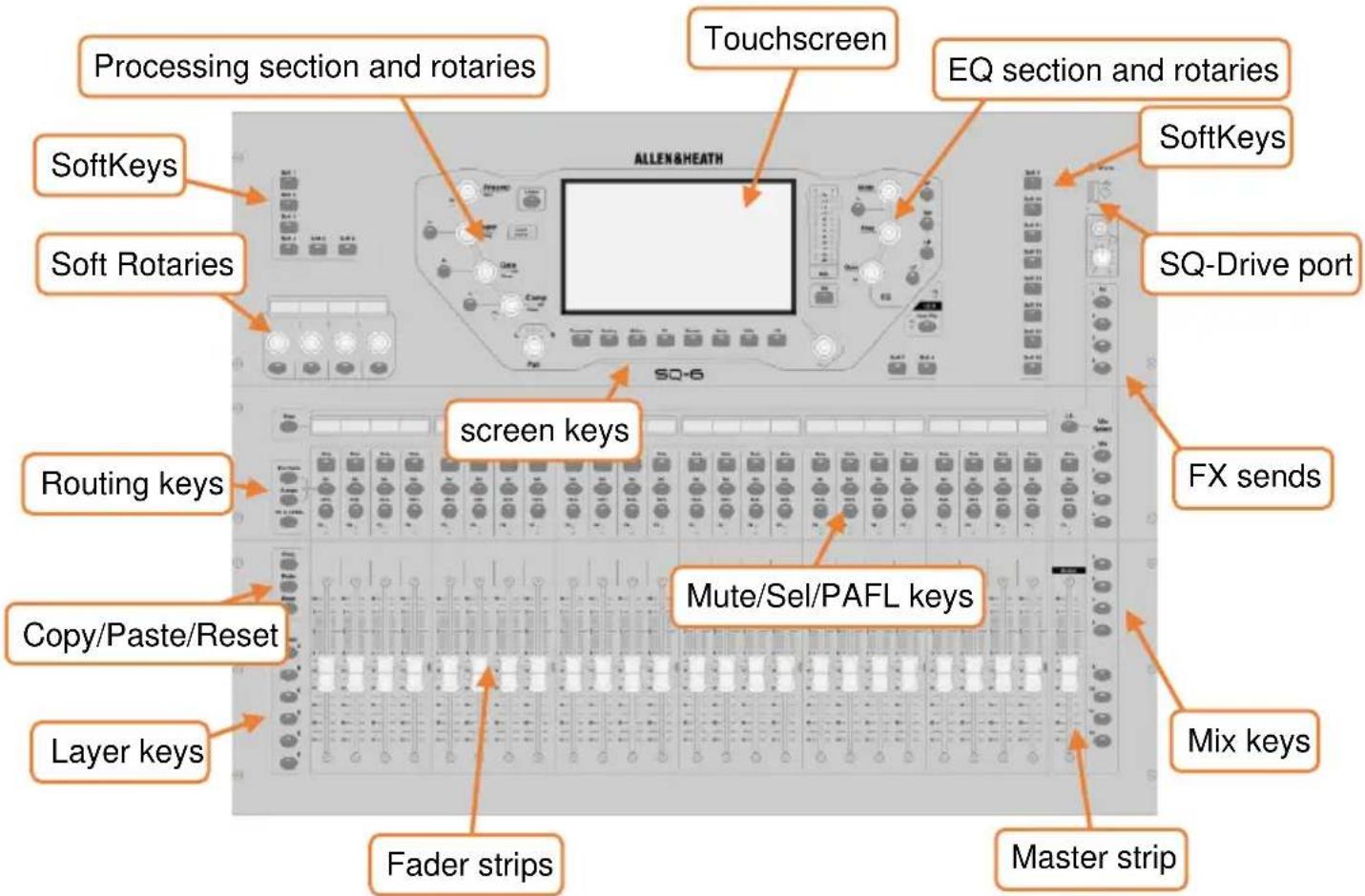
Keys – All keys are labelled, and most illuminate to show when they are active. All perform specific functions, aside from the ‘SoftKeys’ which are user assignable.
Faders/Fader Screen – There are 6 layers of assignable fader strips. For all inputs and FX returns the fader controls the send level of this channel to the selected mix. FX Send, Main LR, Mix (Aux/Group) and Matrix faders control master levels. DCA faders affect the level of the DCA members, and MIDI faders send MIDI level messages. All fader strips are used by the GEQ ‘Fader Flip’ function on the SQ-5, SQ-6 and SQ-7. The SQ-Rack features a dedicated Faders screen in place of physical faders.
Rotary Encoders (Rotaries) – These illuminate when active and are used to adjust various parameters. Some are dedicated to parameters for the currently selected channel or mix, though the SQ-6, SQ-7 and SQ-Rack feature additional ‘Soft Rotaries’ which are user assignable and there is dedicated touchscreen encoder.
Touchscreen – The touchscreen allows simple user interaction through on-screen buttons and menus. Parameters can also be selected on-screen and adjusted using the touchscreen rotary. When a parameter is selected, it will turn yellow on the screen, and the touchscreen rotary will illuminate to indicate it can be used.
4.2 Channel Types
Inputs - 48 input channels with processing. These can be sourced from local, remote or digital connections, and mixed to any output.
Main LR – This is the main mix. All post-fader modes and options follow this mix.
Mix -12 stereo mix channels with processing that can be used as either auxiliaries or groups.
FX Sends - 4 FX send buses are included for use with internal FX engines.
FX Returns - 8 stereo dedicated return channels for internal FX engines.
Matrix - 3 stereo or up to 6 mono matrix mixes, fed from a combination of other mixes.
DCA - 8 'Digitally Controlled Amplifier's for adjusting the level and mutes of multiple channels with one set of controls.
MIDI – 32 channels strips are available which send MIDI control data using MIDI over USB and TCP/IP.
MIDI channel strips only send and respond to MIDI messages, their state is not stored with Scenes or Shows.
4.3 On-screen Parameters, Menus and Pop-ups
Adjustable parameters and selections – These are displayed as white text on a black background. Values are displayed as text as well as in a bar.
Libraries – When available for the screen currently being viewed the 'Library' key illuminates. Pressing this displays a library window, allowing you to store or recall settings for things such as FX units, channel processing or input patches. Presets are stored in the Factory libraries, and User libraries are provided to store your own settings. Libraries are also used to load FX unit types, through recall of a preset.
i Where a library is available, it is noted with the following symbol –
i See the full list of library types in the Libraries section.
Menu lists – With short lists, touch an option to select it. Longer lists can be navigated by touching and dragging, or by highlighting an option and using the touchscreen rotary to scroll through all available options. Where it is not possible to select a list item (as in user permissions lists) you may only touch and drag on screen.
An ‘X’ is displayed to the top right of most pop-up menus, touch this to close the pop-up.
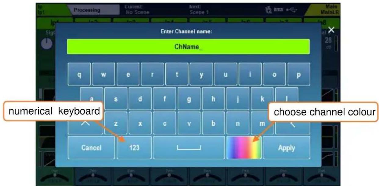
Keyboard – An on-screen keyboard is displayed when entering names or numbers. Touch and hold ‘^’ (shift) to enable caps lock. Touch ‘Apply’ or ‘OK’ to set the name or number. Touch the ‘X’ at the top right of the keyboard to close it.
The standard keyboard has a separate numerical keyboard, and when entering hex characters, a hex-only keyboard is shown.
When entering a Channel Name, touch the colour button to choose a channel colour.
Confirmation – Certain actions require confirmation. Where there is an option to apply or cancel changes, buttons will show as active on-screen. In some cases, a ‘pop-up’ with more information and choices will be displayed.
4.4 On-screen Title bar
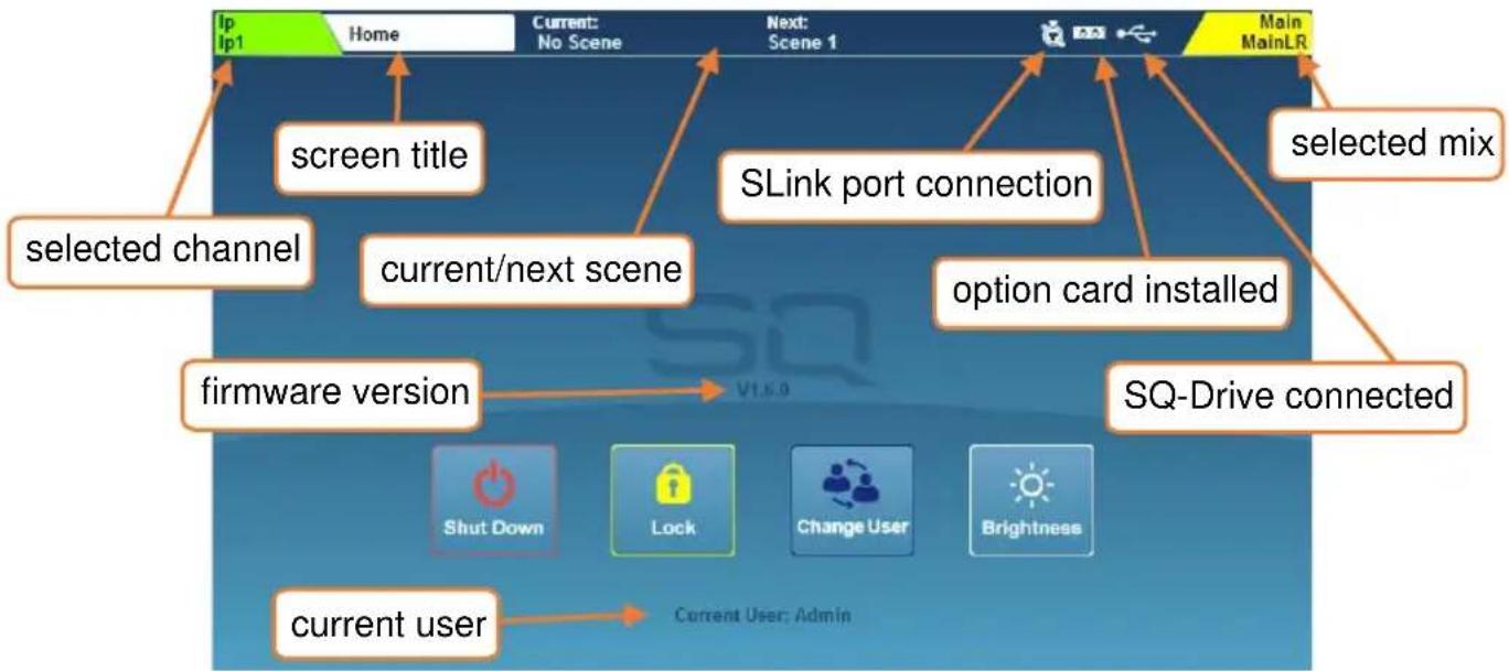
The title bar is always visible at the top of the screen, from left to right it displays the following information:
• The currently selected channel.
• The title of the current screen.
• The last recalled (current) scene.
• The next scene to be recalled.
- An SLink port symbol (when an SLink connection is available).
- A red cross when an error is detected (tap on this to see a pop-up window with the detected error).
- An I/O Port symbol (when an option card is fitted).
- A USB symbol when a USB device is connected to the SQ-Drive port. This is replaced with transport symbols when using SQ-Drive for audio recording or playback.
• The currently selected mix.
4.5 Home Screen
flowchart
graph TD
    A[" screen title "] --> B[" screen Ip1 Home"]
    B --> C[" screen Ip1 Home"]
    D[" selected channel "] --> E[" current/next scene "]
    E --> F[" current next scene "]
    G[" firmware version "] --> H[" firmware version "]
    H --> I[" firmware version "]
    J[" SLink port connection "] --> K[" option card installed "]
    L[" SQ-Drive connected "] --> M[" SQ-Drive connected "]
    N[" Current user "] --> O[" current user; Admin "]
    P[" Main MainLR "] --> Q[" Main MainLR "]
    R[" selected mix "] --> S[" selected mix "]
    T[" Switch Down"] --> U[" Lock"]
    V[" Change User"] --> W[" Brightness"]
This is the first screen shown when powering on the SQ. It is also shown when no channels are selected, and 'Processing' or 'Routing' screen keys are active.
i Pressing the 'Processing' or 'Routing' screen keys in bank view will deselect the currently selected channel and return directly to the home screen.
'Shut Down' – Touch to shut down the SQ.
'Lock' – Touch to lock the SQ surface and prevent adjustments.
'Change User' – Touch to change to another active user.
‘Brightness’ – Touch to go directly to the SQ brightness settings.
4.6 Diagnostics
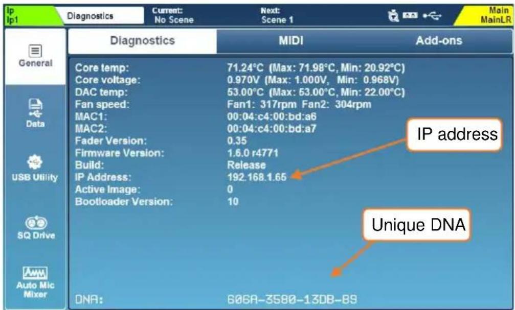
To get to the diagnostics, press the ‘Utilities’ screen key and touch the ‘General’ tab. This displays important information about the SQ, including the current IP address for connecting via TCP/IP, and the unique DNA code for registration and add-ons.
- Press an ‘LR’, ‘Mix’ or ‘FX’ key or select a mix from the ‘Mix Select’ pop-up (SQ-Rack) to display and adjust send levels from each channel to the selected Mix on the Fader Strips or Faders screen (SQ-Rack). Use the layer keys to move through the 6 layers of faders.
The Master strip controls the overall send level of the selected Mix/FX send.
- Select a channel by pressing a 'Sel' key or touching the channel strip in Processing, Routing or Faders screens. The physical controls can now be used to adjust parameters for the selected channel.
- Press Mute to completely mute a channel. Mute keys are illuminated or flash when a channel is muted.
- Use 'PAFL' (Pre/After Fade Listen) keys to route a channel to the PAFL bus/Headphone output.
- Go to the ‘Processing’ screen to see an overview of the processing for the selected strip. Touch on any part of the processing to see a detailed view, then touch a parameter on-screen and use the touchscreen rotary to adjust.
- Mix sends set to ‘Post-Fade’ follow the LR send levels. To toggle channels between ‘Pre-Fade’ and ‘Post-Fade’ for the selected Mix, hold the ‘Pre Fade’ key and use ‘Sel’ keys where available, or use the ‘Routing’ screen.
- To assign or un-assign a channel from the currently selected mix, hold the 'Assign' key and use 'Sel' keys where available, or use the 'Routing' screen.
- Pressing and holding the 'CH to All Mix' key will display the send levels for the currently selected channel to all mixes across the main fader strips.
- Press the ‘FX’ screen key to view and adjust the FX engines. Use the ‘Library’ key to recall FX types and presets - change parameters by selecting them on-screen and using the touchscreen rotary.
FX buses 1 to 4 send to FX engines 1 to 4 by default.
FX Return channels are routed to Mixes in the same way as input channels.
- Hold the 'Copy' key and press an 'In' key, a 'Sel' key or a 'Mix' key to copy parameters or sends.
Hold the ‘Paste’ key and press a ‘Sel’ key or Mix key to paste the processing or send assignments to another channel.
Hold the 'Reset' key and press an 'In' key, a 'Sel' key or a 'Mix' key to reset parameters.
- Press the 'View' key to momentarily show alternative information on the channel strip and Soft Rotary LCD's. Press multiple times to see different information and press and hold to display the information until the key is released.
4.8 SQ-Rack Screens
There are two screens and two pop-ups which are unique to the SQ-Rack.
Faders -
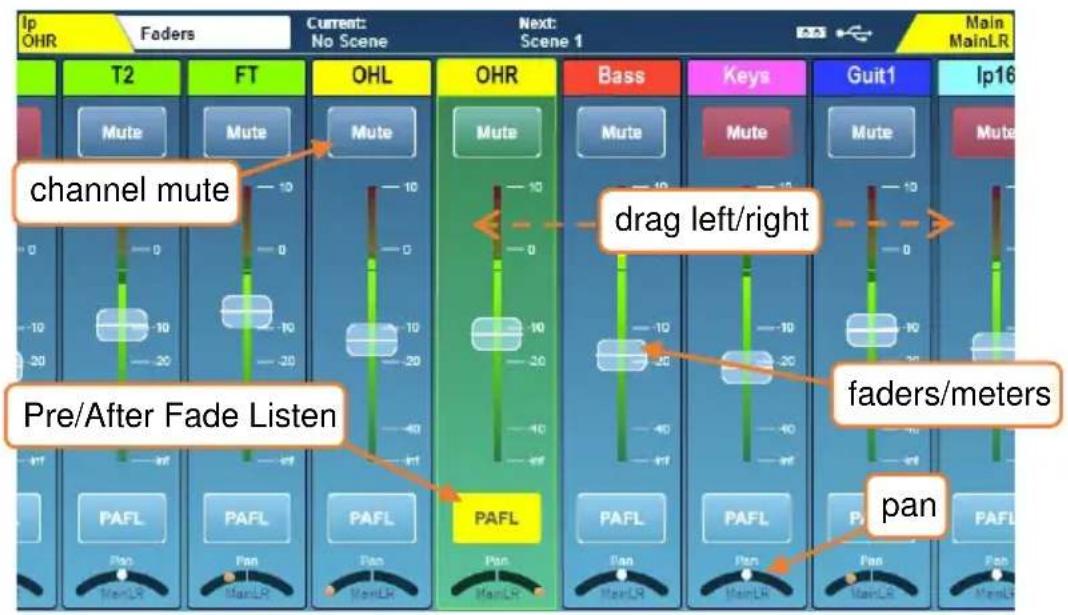
Press the ‘Faders’ screen key to view and adjust send levels, panning and mutes, and to PAFL channels.
- Use 'Layer' keys A-F to the left of the screen to select a layer
- Touch and drag left and right to see up to 16(+Currently Selected Mix) channel strips per layer
- Touch a channel strip to select it. The selected channel persists through Faders, Processing and Routing screens, and can be used by Soft Controls that are set to adjust parameters for the currently selected channel.
- Touch and drag a fader up or down, or touch a fader to select it, then use the touchscreen rotary to adjust send levels to the currently selected mix.
Use the Select Channel Strip and Select Mix pop-ups, explained later in this section, to select different mixes and for quick navigation.
The background of the Faders screen will change colour to show when any mix other than MainLR is selected.
- Touch a ‘Mute’ button to mute that channel
- Touch a ‘PAFL’ button to route that channel to the PAFL bus (headphones)
- Touch ‘Pan’ or ‘Bal’ controls (available when a stereo Mix is selected) and use the touchscreen rotary to adjust.
Select Channel Strip Pop-up –
Touch the currently selected channel in the top left of the screen on the SQ-Rack to display the ‘Select Channel’ Strip pop-up.
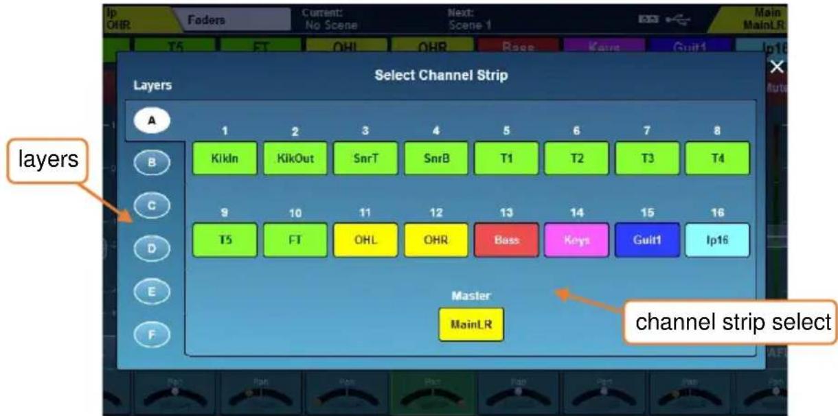
- Use the physical or on-screen layer keys to navigate
- Touch a channel strip to select it
Select Mix Pop-up –
Touch the currently selected mix in the top right of the screen on the SQ-Rack to display the 'Select Mix' pop-up.
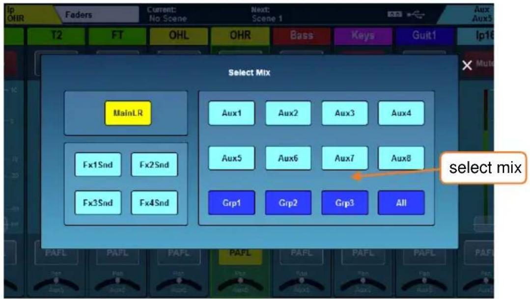
- Touch a mix to select it and display send levels to that mix on the Faders
SQ-Control -
SQ-Control offers simplified, customisable control of main mixer functions.
It features 5 'Tabs', each of which can contain up to 48 control 'Widgets'.
There is an accompanying SQ-Control app available for all SQ models, and all instances of the app, along with the dedicated SQ-Control screen of the SQ-Rack, display and use the same widget layout.
The layout of all 5 tabs is stored in the current scene. However, by default, changes to the SQ-Control layout when recalling Scenes is blocked by Global Filters.
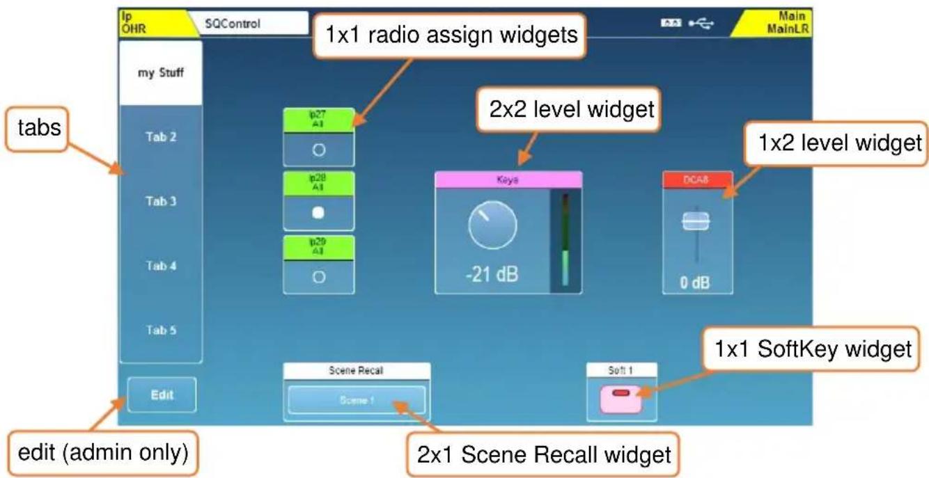
Each widget controls a single function and depending on the assigned function, can take up 2x2, 2x1, 1x2 or 1x1 widget slots.
- Touch on one of the 5 tabs on the left of the screen to view.
- Touch to select any level, fader or rotary widget and use the touchscreen rotary to adjust.
- Touch any mute, assign, scene recall or SoftKey button to action it.
Level widgets are used to control either a main channel level (e.g. Input to MainLR mix or Mix Output level) or a send level from a source (e.g. an input) to a destination (e.g. a mix).
Mute widgets include channel mutes, along with Mute Groups and DCA Mutes. These mute channels for all mixes or outputs.
A 'standard' assign widget turns the entire signal from a source to a destination on (assigned) or off (unassigned).
A radio assign widget works by only allowing one source (e.g. input channel) to be assigned to each destination (e.g. mix) per SQ Control tab. In practice this is used to choose between a selection of sources for a particular output, for example, switching between background music or a TV audio feed.
Meter widgets display the main channel meter for any input or mix. Note that some level widgets also include meters.
Scene Recall widgets recall one of the 300 Scenes stored in the desk. A Scene is a stored state of the mixer, and includes all processing, routing and level settings.
The SoftKey widgets match the physical SoftKeys controls and are mainly included for use in the SQ-Control app.
Editing the SQ-Control layout -
When logged in as the admin user, press the 'Edit' button to enter or exit edit mode. When editing, all empty widget slots will have a + symbol in them.
- Touch the name of the selected tab to rename it
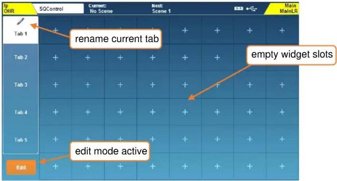
Touch one of the widget slots or an existing widget to open the editing pop-up.
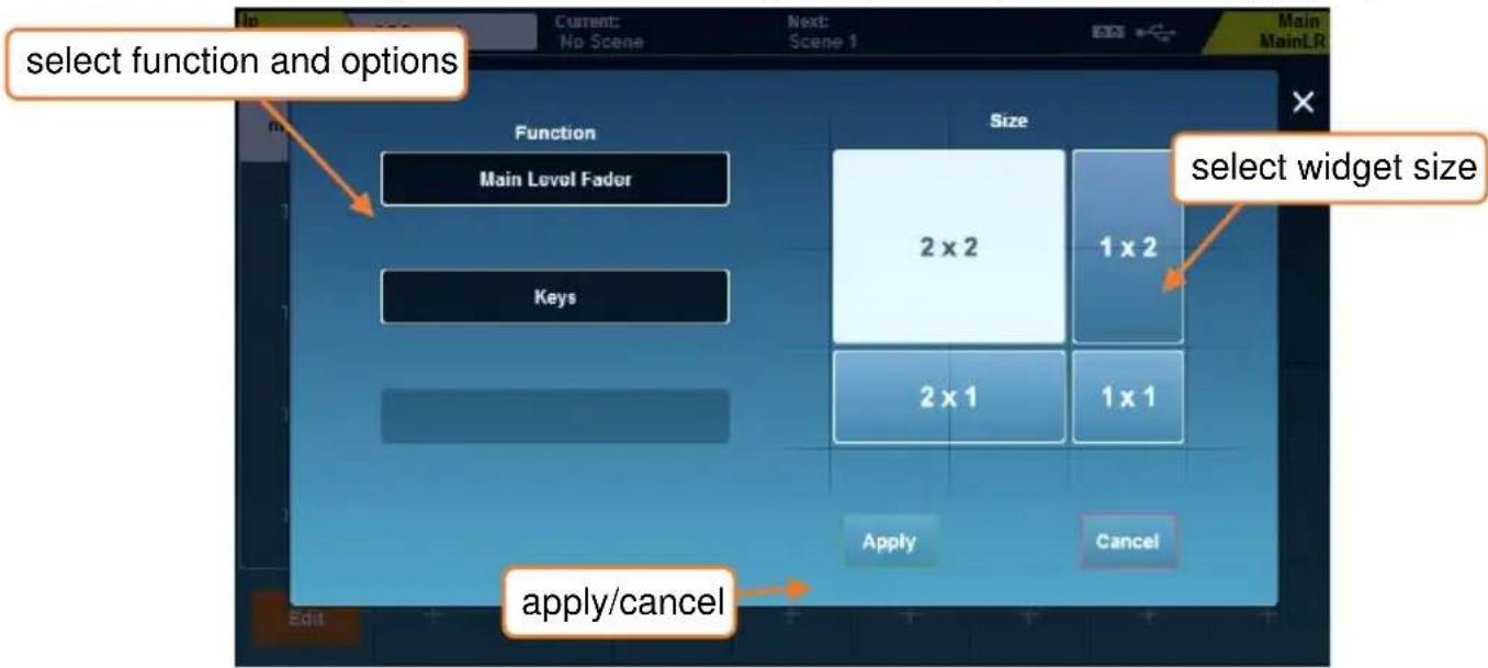
1) Select a function for the widget
2) Select a source (channel) or secondary option
3) Select a destination (mix) or third option
4) Select the size for the widget. Depending on function and available space, not all sizes will be displayed for selection.
5) Press 'Apply' to add the widget
6) Repeat for each widget and each tab as required
4.9 Screens Reference
| Screen Key | Option 1/Left Tabs | Option 2/Top Tabs |
| SQ-Control (SQ-Rack only) | Tabs 1-5 and Edit | N/A |
| Faders (SQ-Rack only) | N/A | N/A |
| Processing | Name, Preamp (input)/Ext In (mix), HPF (input), Gate (input), FX unit (FX Snd/Rtn), Insert, GEQ (mix), PEQ, Compressor | Bank/Processing View |
| Routing | Name, Direct Out/Group/Aux Snd/FX Snd, DCA/Mute Assign, Mix Sends, FX Sends (input)/Matrix Sends (mix) | Bank/Assign and Level View |
| Meters | Input Meters | N/A |
| FX Meters | ||
| Mix Meters | ||
| USB Meters | ||
| RTA | ||
| Channel Meters | ||
| FX | FX Engines 1-8 | Front/Back Panel |
| Scenes | Scene Manager | All Scenes/Cue List |
| Cue List Editor | N/A | |
| Global Filter | Input/FX | |
| Mix | ||
| Other | ||
| Safes | Inputs | |
| FX | ||
| Mix | ||
| Setup | Audio | PAFL |
| Talkback | ||
| SigGen | ||
| Digital I/O | ||
| I/O Port | ||
| Surface | Strip Assign | |
| Soft Controls | ||
| Footswitch | ||
| Surface Prefs | ||
| Mixer Config | Input Stereo | |
| Mix Stereo | ||
| Bus Config | ||
| Role | ||
| Ganging | Gangs 1-8 | |
| Network Setup | N/A | |
| Users | User Settings | |
| Setup | ||
| Parameters | ||
| Control | ||
| Utility | General | Diagnostics |
| Calibration | ||
| MIDI | ||
| Add-ons | ||
| Data | Shows | |
| Scenes | ||
| Libraries | ||
| Sync | ||
| USB Utility | Status/Format | |
| Firmware Update | ||
| SQ-Drive | Stereo | |
| Multitrack | ||
| Auto Mic Mixer | Overview | |
| Input Assign | ||
| Setup | ||
| I/O | Inputs/Input channel | Input sockets |
| Inputs/Mix Ext In | ||
| Outputs/IP Direct Out | Output sockets | |
| Outputs/Mix Out | ||
| Outputs/Rack FX | ||
| Outputs/Monitor Out | ||
| Tie Lines/All Input sockets | All Output sockets |
5. Connections
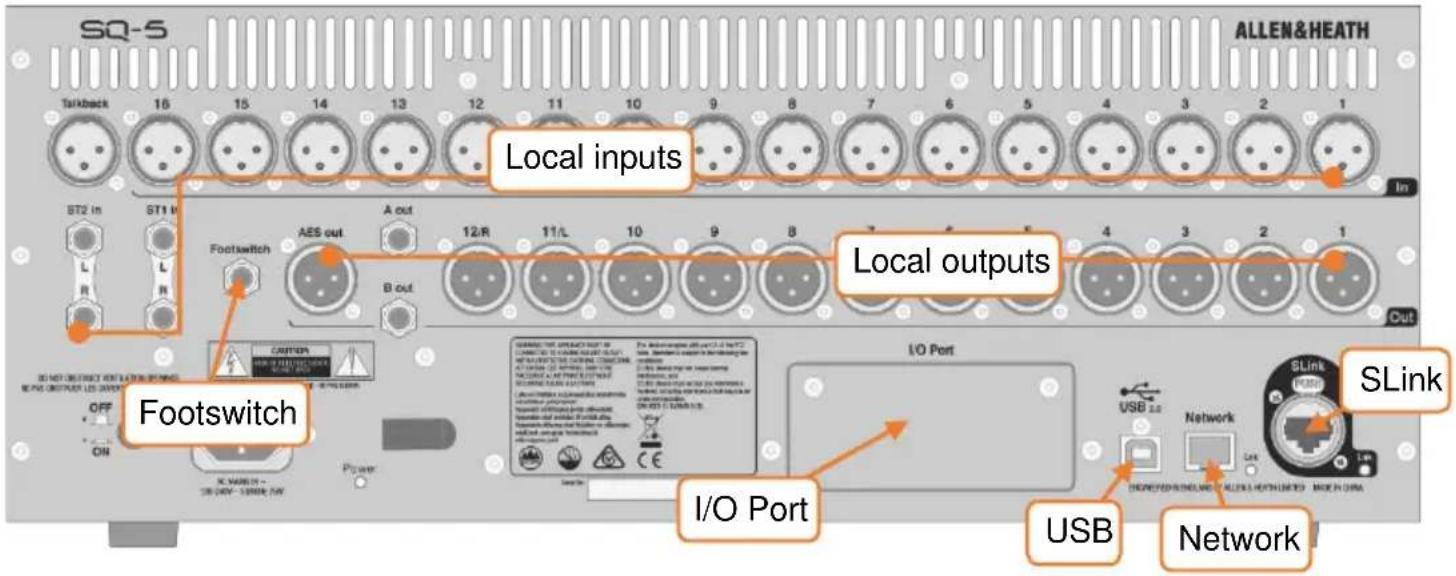
5.1 Local Inputs
Mono mic/line (XLR female) – These are numbered and accept balanced mic or line level signal. Gain, Pad and 48v Phantom Power are controlled digitally.
Talkback (XLR female) – Identical to mono mic/line inputs. Intended for communication from the desk position but can also be used as an additional input.
ST1, ST2 (1/4" TRS jack) – Labelled as stereo pairs, these can also be used as mono line level balanced inputs.
ST3 (TRS Mini jack) – Located on the surface of the SQ, this can be used with a line level source, such as a portable media player, laptop, tablet or smartphone, using a standard stereo mini jack cable.
5.2 Local Outputs
Mono line (XLR male) – Line level outputs for sending mixes or direct outputs. These are numbered, and fully assignable. With default settings, the LR mix is sent to 11&12, as labelled.
A/B mono line (1/4" TRS jack) – Two assignable line level outputs, presented on balanced jack sockets for convenience.
AES digital (XLR male) – Stereo digital output clocked to SQ. For connection to equipment with a digital input.
Headphone (1/4" TRS jack) – Located on the surface of the SQ, with dedicated level control. Fed from the PAFL bus.
5.3 SLink
Digital multichannel audio (etherCON) – For expanding the SQ using Allen & Heath Everything I/O range of expanders. Mode automatically switches between dSnake/ME, DX and gigaACE/GX protocols.
| Protocol | Sample Rate | Max Inputs | Max Outputs |
| dSnake/ME | 48kHz | 40 | 20 (+40 ME) |
| DX | 96kHz | 32 | 32 |
| gigaACE/GX | 96kHz | 128 | 128 |
i SLink does not support multiple protocols on a single connection.
Check www.allen-heath.com for the latest 'SLink Connections' document to see supported configurations for the current firmware.
5.4 USB
SQ-Drive – Located on the surface of the SQ. Can be used to connect USB ‘pen/stick’ drives, or portable HDD’s or SSD’s. Used for storing and recalling data, firmware updates and stereo or multitrack audio recording and playback.
USB-B – For connection to a Windows or Mac computer, in order to use the built-in 32x32 audio and MIDI interface.
See the SQ-Drive and USB-B section for more information.
5.5 Network
This is used to connect the SQ to a wireless router, access point, local area network or directly to a device, allowing the SQ to transmit and receive control data. For use with Allen & Heath SQ apps, and for MIDI over TCP/IP.
5.6 I/O Port
For the connection of SQ option cards, allowing expansion and connectivity using Allen & Heath (SLink) or third-party protocols (including Dante, Waves and MADI).
See www.allen-heath.com for all available option cards.
5.7 Footswitch
Connect a single or dual, momentary or latching footswitch, and use to control functions such as mutes, tap tempo or scene changes.
See the Footswitch Setup section for more information.
6. I/O Patching
I/O patching allows input processing channels to be fed from any input socket, and for any output socket to be fed from any direct, mix or FX output. It's also possible to route signals around the system without any channel processing.
There are two ways to patch input sockets to input processing channels, either in the Preamp section of the channel processing screen, or in the I/O screen. For patching multiple input channels, it is easiest to use the I/O patching screen, which is also used for all output patching.
Press the 'I/O' screen key to display the patching matrix. This is a grid of patching blocks where each block is a crosspoint representing a connection.
6.1 Patching
- Touch one of the tabs on the far left then select one of the following:
'Inputs' > 'Input Channel' = Patch input sockets from the top to input channels of the SQ on the left for mixing.
'Inputs' > 'Mix Ext In' = Patch input sockets from the top, directly into a mix of the SQ on the left (without any processing, level or mute control).
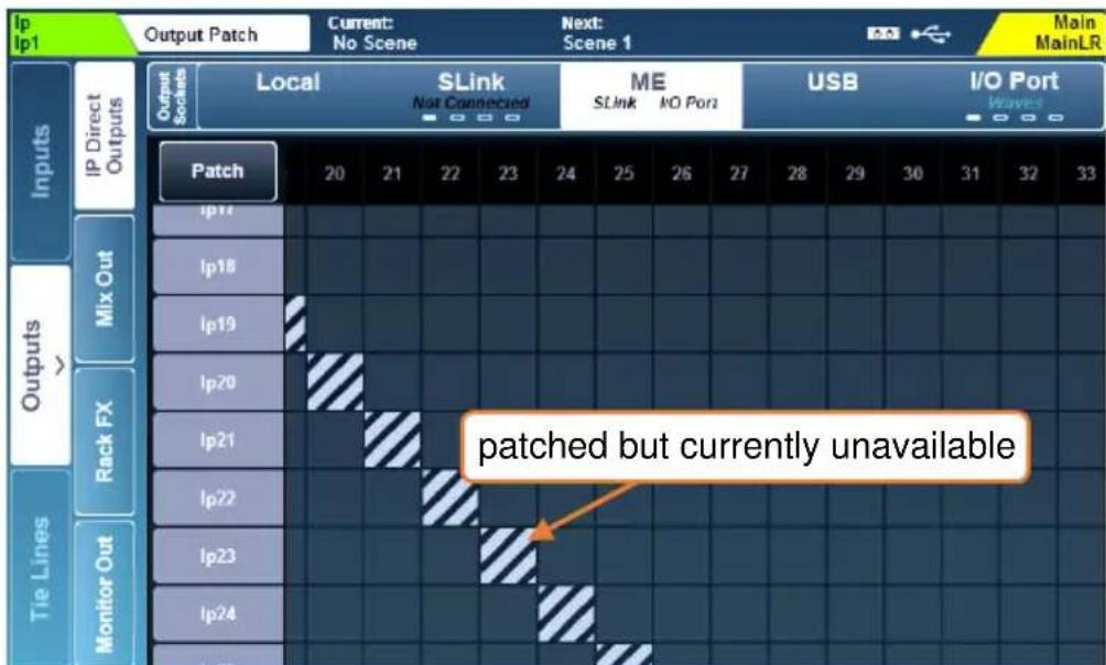
'Outputs' > 'Direct Outs' = Patch from the direct outputs of input channels on the left to any output socket at the top.
'Outputs' > 'Mix Outs' = Patch from mix outputs of the SQ on the left (LR, Aux, Group, Matrix), to any output socket at the top.
'Outputs' > 'Rack FX' = Patch from FX return channels in the SQ (the 'wet' FX signal) on the left to any output socket at the top.
'Outputs' > 'Listen Out' = Patch from PAFL, talkback and Listen outputs in the SQ on the left to any output socket at the top.
'Tie Lines' = Patch directly from any input socket on the left to any output socket at the top (without any processing, level or mute control).
- When patching inputs, the input sockets are displayed at the top of the matrix and the destination channel (in the SQ) is displayed to the left.
- When patching outputs, the source (from the SQ) is displayed at the left of the matrix, and the output sockets are displayed at the top.
- When patching Tie Lines, input sources are shown on the left and output destinations are shown at the top.
- Touch and drag the grid on-screen to see more input and output channels.
- Touch the 'SLink' or 'I/O Port' tab multiple times to display channels 1-32, 33-64, 65-96 or 97-128. There are four marks on each tab to show which screen is currently displayed.
Patching a Source to a Destination –
- Touch the 'Patch' button on the screen at the top left of the patching matrix to enable patching.
- Touch a patching block on the matrix to make or delete a patch.
• Available patching blocks are grey and are filled light grey when patched.
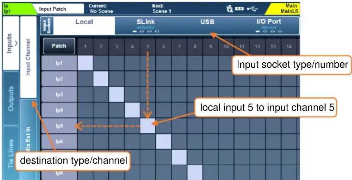
- Currently unavailable patching blocks are dark grey and striped light grey when patched.
- Input or Output sockets that are currently in use are dark grey (including if they are being used by insert points). Sockets that are not in use are light grey.
The Patch switch will be turned off automatically whenever leaving the I/O screen. It can be disabled entirely in the Surface Prefs screen.
① All patching to a currently disconnected device will become active once the device is connected.
Sequential Patching –
For quick sequential patching (also known as ‘block’, ‘one-to-one’ or ‘diagonal patching’)
- Touch and hold the first available (unpatched) patching block you wish to patch to until the touchscreen rotary illuminates.
- Turn the touchscreen rotary increase or decrease the number of channels you wish to patch; these are displayed as blue patching blocks.
- Remove finger from screen to apply patching.
① It is not possible to delete patches sequentially, so the starting patching block must be currently unpatched.
Input Channel Patch Libraries –
Pressing the ‘Library’ key on the surface when the ‘Input Channel’ tab under ‘Inputs’ is active will display the IP Channel Patch Libraries.
These can be used to store and recall input channel patching for different setups and provide a quick method of switching the entire input patch for virtual soundcheck.
For quick setup, factory presets for one-to-one patching from each input type are provided.
i Input libraries store and recall all input patching, not just the currently selected source.
6.2 Local Sockets
The local input and output options in the I/O screen match the analogue input and output socket labels on the SQ.
6.3 SLink Sockets
The SLink port is compatible with dSnake, DX and gigaACE/GX. It switches between these modes, so multiple protocols over a single connection are not supported.
The current mode is shown on the tab in blue text unless nothing is connected, in which case 'Not Connected' is displayed.
Check www.allen-heath.com for the full list of supported configurations.
Touch the tab multiple times to display channels 1-32, 33-64, 65-96 or 97-128. There are four marks on each tab to show which screen is currently displayed.
6.4 ME Systems
ME-U, ME-1 and ME-500 units use the dSnake protocol, so can either be connected directly, or connected to the monitor or expander ports of an AR2412 or AB168.
The ME patching is applied to any SLink port that is running the dSnake protocol, which could be the SLink port, an SLink option card, or both at the same time. The 'SLink' and/or 'I/O Port' text on the 'ME' tab are displayed in white when patching is active on either port.
ME-U and ME-1 units can accept 40 total channels, ME-500 units accept 16 mono or stereo channels.
Stereo channels are set on the SQ in Mixer Config settings and should be patched to odd/even channel pairs when using ME-500 units.
ME-500 units automatically assign the first 16 stereo or mono sources they receive to the 16 available keys.
6.5 USB-B and SQ-Drive Channels
USB inputs and outputs can either be used by the USB-B connection or SQ-Drive.
To view or change USB mode, press the 'Setup' key, then touch the 'Audio' tab followed by the 'USB' tab.
See the SQ-Drive and USB-B section for more information on streaming and recording audio.
6.6 I/O Port Channels
The I/O Port is for patching to and from SQ option cards fitted in the I/O Port.
The current option card protocol is shown on the tab in blue text unless nothing is connected, in which case 'Not Connected' is displayed.
i Touch the tab multiple times to display channels 1-32, 33-64, 65-96 or 97-128. There are four marks on each tab to show which screen is currently displayed.
Note that when patching to an option card such as Dante or Waves, you are patching the SQ to the option card. Further patching between devices is usually then required.
6.7 Tie Lines
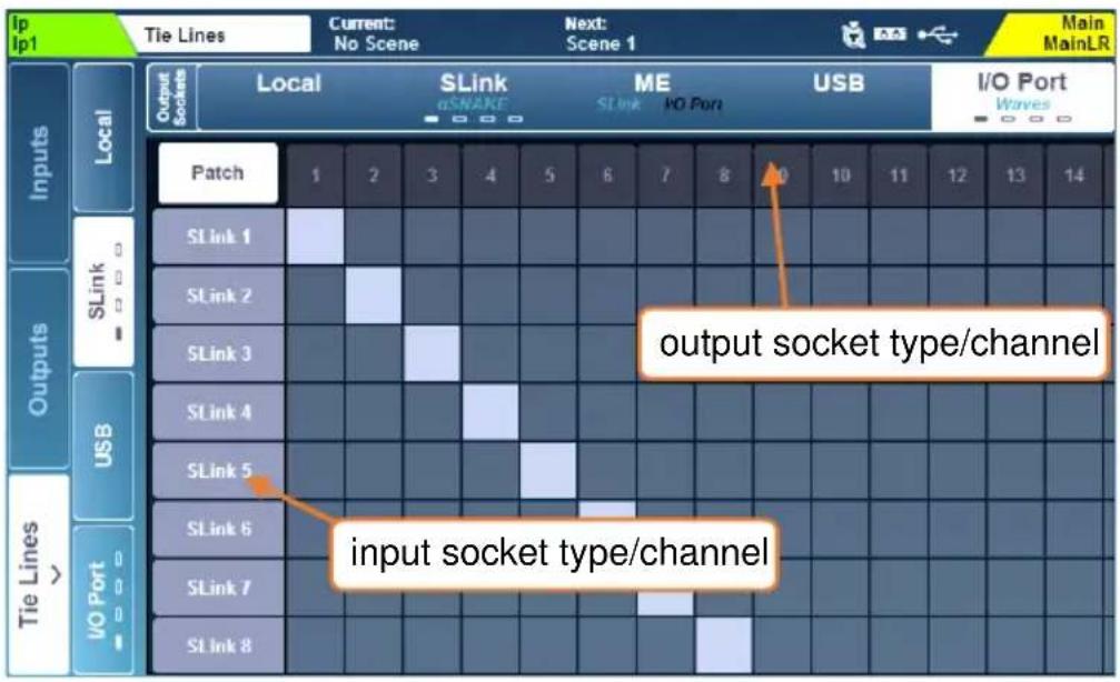
Tie lines are used to patch connections directly from any input socket to any output socket without using any of the channel processing, mixing or level control in the core.
They are different from input direct outputs, which come from the 48 input processing channels and can include processing.
All possible input sockets are displayed on the left and all possible output sockets are displayed at the top.
Tie lines allow you to pass audio directly from any available input source to one or multiple outputs and have many applications including:
- Sending unprocessed (post socket analogue preamp) audio whilst simultaneously sending processed audio from a input direct out (such as when multitrack recording and using a ME personal monitoring system at the same time).
- Setting up digital splits for front of house and monitor or broadcast setups.
- Sending an ambient microphone (not required in any mix) to USB or option card for recording without using up an input channel.
To protect preamp settings for sockets not assigned to input channels on scene changes, block 'Tie Line Only Preamps' in Global or Scene recall filters.
6.8 Socket Control
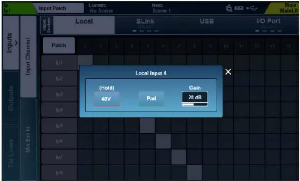
Touching a socket number at the top of the patching matrix opens the socket control pop-up with the following options for connected local or expander sockets.
Analogue input = 48V, Pad and Gain
AES input = SRC Bypass option
All output sockets = Polarity (invert)
AES output = Output Sample Rate
7. Processing
Press any 'Sel' key to select a channel. The physical controls and keys around the touchscreen will illuminate to show they are active and can be used to adjust parameters for the selected channel.
Press the 'Processing' screen key to display the processing 'bank view'.
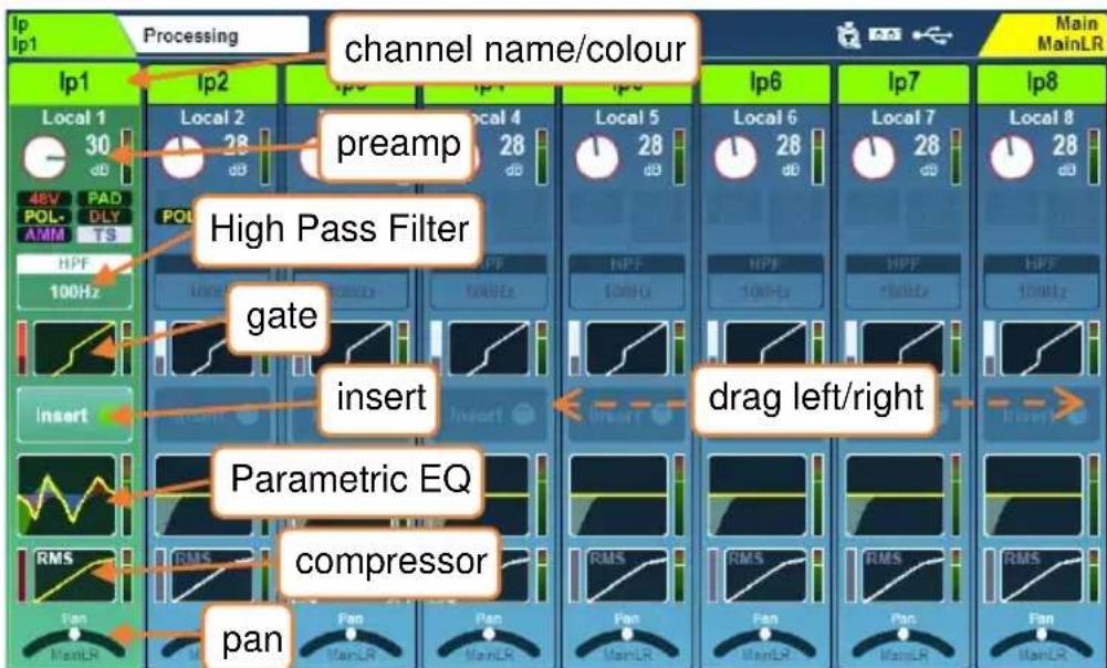
This gives the processing overview for up to 8 channels at once, with the selected channel highlighted. The view will automatically change if a channel is selected which is out of view, though you can also touch and drag to see all channels in the current layer.
The currently selected mix channel is displayed to the far right.
- Touch a channel name to rename and change channel colour.
- Touch 'Apply' to set the name and colour (it will then be displayed on the screen and channel LCD display).
The keyboard remains on screen when other 'Sel' keys are pressed, to speed up the naming of multiple channels.
- Touch any processing ‘block’ to view and adjust it in detail. The overview for the selected channel will continue to be shown at the left of the screen. Selecting another channel of the same type will allow you to adjust the same parameters on the newly selected channel.
- Touch the active block or press the 'Processing' key to return to the bank view.
- The order of audio signal processing is displayed from top to bottom.
DCA channels display a list of up to 28 'members'. If there are more members than this, then '…' will appear at the bottom of the list.
7.1 Preamp (Input Channels)
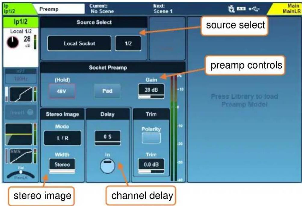
Source Select –
- Touch the source type to select from a list of sources.
Unassigned = Channel has no source.
Local Socket = A socket on the rear of the SQ.
SLink Socket = A device connected to the SLink port
(AR, AB, DX, GX units or another console).
USB Port = Either SQ-Drive or USB-B (depending on which is in use).
IO Port = SQ Option card.
Signal Generator = The built-in signal generator.
- Touch the socket number and use the touchscreen rotary to scroll through all available sockets.
Socket Preamp –
When the source is set to a socket with a preamp, the '48V', 'Pad' and 'Gain' parameters will become available. These are digital controls for the remote preamp and not a part of the channel processing.
When using Dante expanders, the expander socket should be patched to the Dante option card, which is subsequently patched to an SQ channel from IO Port sockets.
i Socket control is also available in the I/O screen.
- Touch and hold the '48V' button to switch phantom power on or off (channel will be automatically muted for a period after switching).
- Touch the 'Pad' button to switch the -20dB pad in or out.
- Select 'Gain' or 'Trim' parameters to adjust using the touchscreen rotary.
Gain = 0dB to +60dB
Trim = -24dB to +24dB
Gain is for digitally controlled analogue inputs, such as local or expander input sockets. Trim is a purely digital adjustment, for digital or line signal and part of the channel processing.
- Touch the 'Pol' button to invert the polarity of the input channel.
Delay – In order of processing, the channel delay is located after the compressor. It is presented in the preamp screen as it is usually set at the same time as other ‘setup’ parameters such as gain, which are not adjusted during mixing.
- Select the value to adjust using the touchscreen rotary.
Input channel delay = 0.00ms to 341.00ms
Or 0.00m to 121.23m (-20°C to +40°C)
Or 0.00ft to 397.76ft (-4°F to +104°F)
Or 0S to 32736S
The units used to measure delay are chosen in the Surface Preferences screen.
- Touch the 'In' button to switch the delay in or out.
Stereo Image – This section is visible only when a stereo input channel is selected. Touch the mode to select from the following options:
L/R = standard left/right.
R/L = switched left/right.
L-Pol/R = standard left/right with switched polarity on left.
R-Pol/L = switched left/right with switched polarity on right.
Mono = left and right fed to both channels.
L/L = left fed to both channels.
R/R = right fed to both channels.
M/S = for decoding a mid/side array (outputs M+S/M-S).
For normal M/S use, the mid signal/microphone should be patched to the odd channel and the side signal/microphone should be patched to the even channel.
The width control can be adjusted in 1% increments from Mono (0%) to Stereo (100%).
DEEP Preamp –
Preamps in the SQ itself and those in Remote Audio Units are accurate and transparent, with fast transients and low THD. However, there are some situations where alternative characteristics may be desirable. Using a DEEP preamp model allows you to add these characteristics, with complete control, and none of the associated limitations or reliability concerns of esoteric equipment.
- When in the channel ‘Preamp’ screen, press the ‘Library’ key to show the list of preamp models.
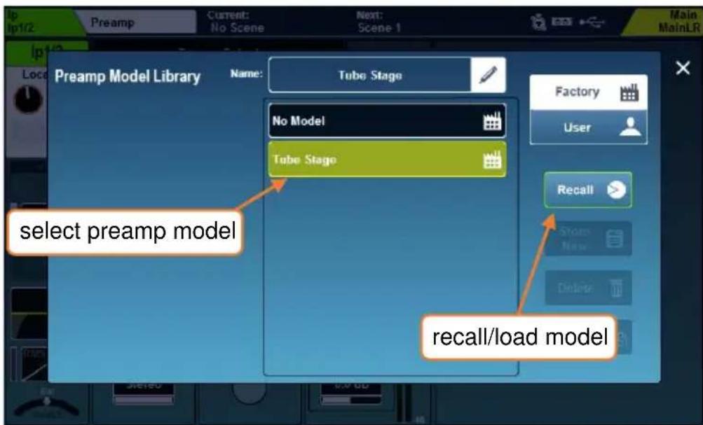
- Select a preamp preset, then press the 'Recall' button to load it.
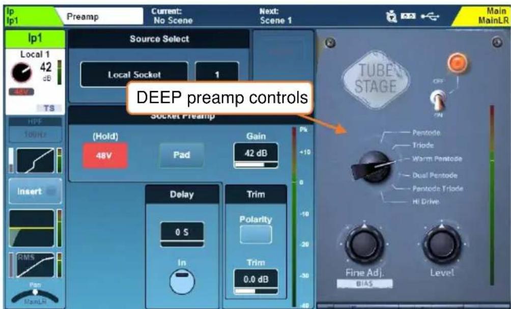
- Touch 'On/Off' to switch the preamp model on or off.
- Touch any on-screen parameter and adjust using the touchscreen rotary.
7.2 Preamp (Mix Channels)
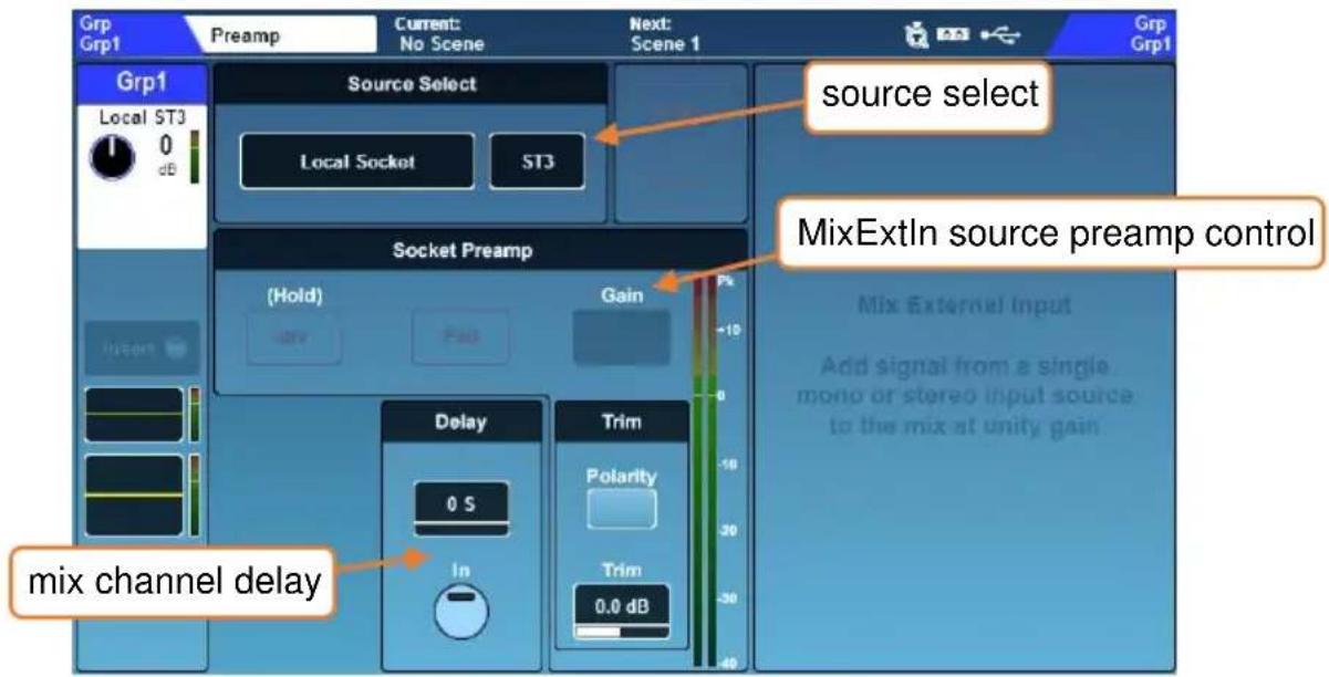
Mix External In –
A ‘Mix Ext In’ can be used with any mix channel. This routes audio directly from a source to the mix without processing, or any routing and level control. It is commonly used to add a pre-processed signal to a mix, such as from a sub mixer or click track.
① Mono mixes allow mono external inputs and stereo mixes allow stereo external inputs.
Other than the channel delay, all parameters in the preamp section of mix processing relate to the control of the mix external input, including Source Select, Socket Preamp (available when a socket preamp is selected as the source) and Trim. Refer to Preamp (input channels) for more information.
Note that the ‘Polarity’ switch and Trim control affect the polarity and trim of the assigned ‘Mix Ext In’, and not the mix channel output. Output polarity can be switched via output socket control in the IO screen.
Delay (mix channel output delay) –
In order of signal processing, this delay is located at the end of the mix channel, after the compressor.
- Select the value to adjust using the touchscreen rotary.
Mix channel delay = = 0.00 ms to 682.00 ms
Or 0.00 m to 242.47 m (-20°C to +40°C)
Or 0.00 ft to 795.53 ft (-4°F to +104°F)
Or 0 S to 65472 S
- Touch the 'In' button to switch the delay in or out.
The units used to measure delay are chosen in the Surface Preferences screen.
7.3 HPF (Input Channels)
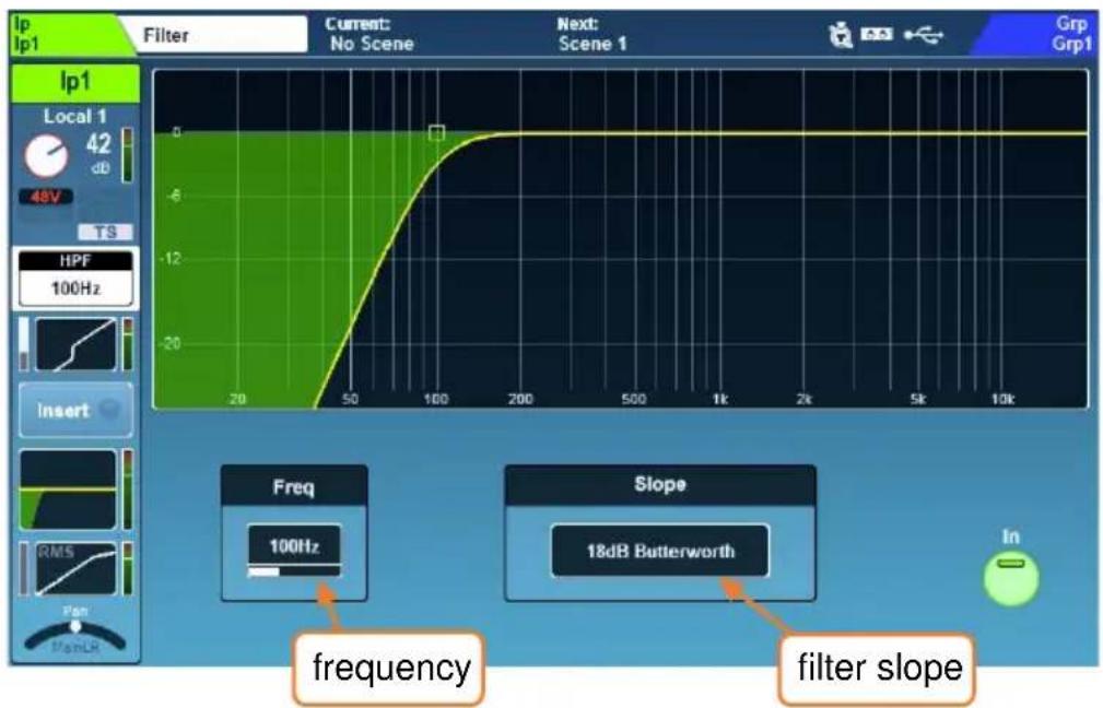
HPF -
A High Pass Filter (HPF) is available on every input channel and features an adjustable slope and frequency.
- Switch in or out using the on-screen button or using the dedicated HPF 'In' key.
- Touch the HPF Frequency value to select it, then adjust using the touchscreen rotary, or use the dedicated HPF 'Freq' rotary to affect the selected input channel.
- Touch the current 'Slope' value to select from different filter slopes.
HPF Frequency = 20Hz to 2Khz
Slope = 12dB, 18dB, 24dB (attenuation per octave) Butterworth
The HPF is also visible on the PEQ processing screen for convenience and can be stored and recalled with PEQ settings. Though as a separate process at a different point in the signal path, HPF does not contribute to the PEQ response curve.
7.4 Gate (Input Channels)
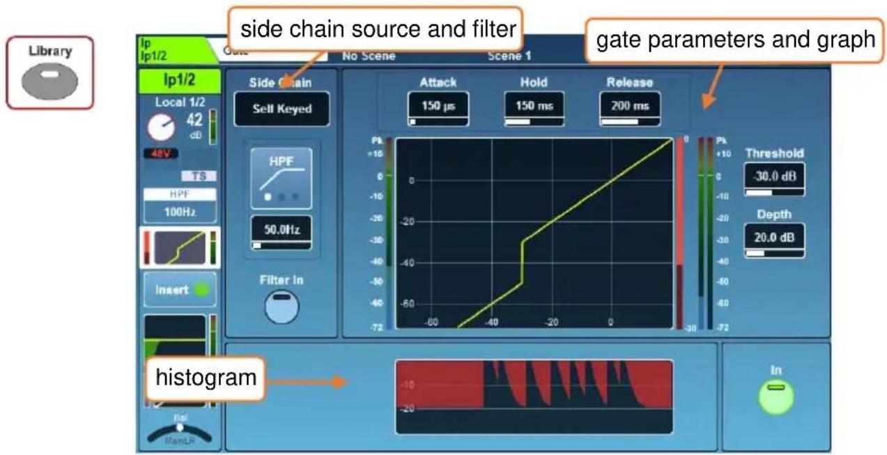
Switch the Gate in or out using either the on-screen 'In' button or the physical Gate 'In' key (to the left of the dedicated Gate threshold rotary).
Side Chain –
- Select either 'Self Keyed' or side chain the gate from another channel.
When using another channel as a side chain input, the signal is sourced after all channel processing, post millisecond channel delay.
- Touch the filter type to switch between HPF/BPF/LPF modes. The 'Filter In' button engages the filter.
- Touch the frequency value to select it, then adjust with the touchscreen rotary.
HPF Frequency = 20Hz to 5kHz
BPF Frequency = 120Hz to 10kHz
LPF Frequency = 120Hz to 20kHz
Parameters and graph –
- The graph displays input/threshold on the x-axis and output level on the y-axis to give a visual representation of gate parameter settings.
- The side chain input level is shown on the meter to the left of the graph.
Gate action (signal reduction) from 0dB to -30dB is shown on the meter to the immediate right of the graph. When the gate is switched in, this is red, otherwise it is white.
The post-gate level is shown to the right of this.
- Adjust parameters by touching to select and then using the touchscreen rotary.
Gate threshold also has a dedicated rotary.
Attack = 50μs to 300ms
Hold = 10ms to 5secs
Release = 10ms to 1sec
Threshold = -72dB to +18dB
Depth = 0dB to 60dB
Histogram –
The histogram shows the previous 12 seconds of gate activity, moving from right to left. As with the reduction meter, when the gate is in, the level reduction (depth) is shown in red, and when out is shown in white/grey.
7.5 Insert
The insert points on SQ can be used to route audio to and from any available I/O sockets, allowing analogue or digital processing to be inserted into the channel.
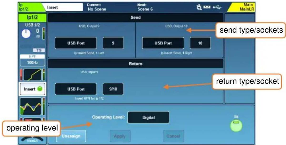
Inserts can also be used with the internal FX engines. See the FX engines section for more details.
Send - Select destination type and channel for the insert send.
Return - Select source type and channel for the insert return.
Send/Return types = Local Socket, SLink Socket, USB Port, IO Port, FX Unit
① Note that insert send and return is not latency compensated.
Operating level – Select from line level options to match insert type.
Digital = Uncompensated, for use with digital I/O. Analogue = For use with +4dBu outboard equipment. -10 dBV = For use with -10dBV outboard equipment.
- Switch the insert in or out by using the on-screen 'In' button.
- Unassign all send and return sockets with the 'Unassign' button.
When a selected channel's insert is assigned and switched 'In', the 'Insert Active' LED will illuminate on the surface.
① Sockets used by insert points are identified as ‘in use’ by the colouring of the socket number in the I/O screen.
If sockets have been set and then patched elsewhere, the insert may become invalid. In this state 'Insert Invalid' will be displayed on the right of the screen and the insert will be switched out.
7.6 GEQ (Mix Channels)
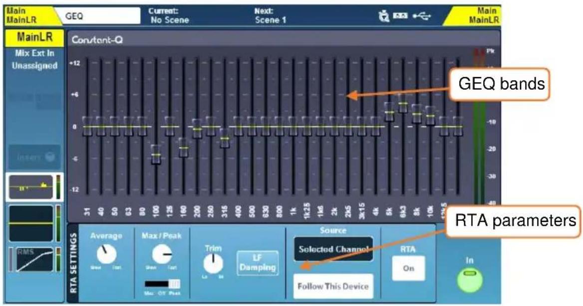
All mix channels feature a 28-band stereo graphic EQ which can be switched in or out by using the on-screen 'In' button.
With a mix channel selected, and GEQ active, the green 'In' LED in the GEQ section (below the PEQ rotaries) will illuminate.
To make adjustments, touch the on-screen fader for each band and use the touchscreen rotary.
$$ \begin{array}{l} \text {Frequencies (Hz) = 31, 40, 50, 63, 80, 100, 125, 160, 200, 250, 315, 400,} \ \text {500, 630, 800, 1k, 1.25k, 1.6k, 2k, 2.5k, 3.15k, 4k, 5k, 6.3k, 8k, 10k, 12.5k, 16k} \ \text {Gain = -12dB to +12dB} \ \text {Bandwidth = 1/3^{rd} oct (constant)} \end{array} $$
'Fader Flip' mode –
The SQ can display the GEQ on faders, with each channel strip showing a single frequency band to allow for quick and accurate adjustment.
- Pressing the GEQ ‘Fader Flip’ key shows the graphic EQ for the selected mix on faders, with a frequency band on each fader strip. Pressing the ‘Fader Flip’ key a second time on the SQ-5 or SQ-6 displays the next set of frequency bands, and a third press will exit the mode.
In ‘Fader Flip’ mode, the chromatic channel meters and peak indicators can be used to show RTA levels and prominent frequency. See the RTA – GEQ ‘Fader Flip’ section for full details.
RTA – The RTA displays the levels of the RTA source for each frequency band of the GEQ.
For full information on the GEQ RTA see the RTA section of this guide.
DEEP GEQ -
Along with the ‘Constant-Q’ GEQ, other DEEP GEQ’s with unique characteristics can be added to the SQ.
Once added to the SQ, these can be used in place of the ‘Constant-Q’ GEQ on any mix channel.
Information on how to add models can be found in the Add-ons section of this guide.
- Press the 'Library' key to see the GEQ Library.
- Different GEQ models are recalled from the 'Factory' library.
- Store and Recall DEEP GEQ user presets using the 'User' library.
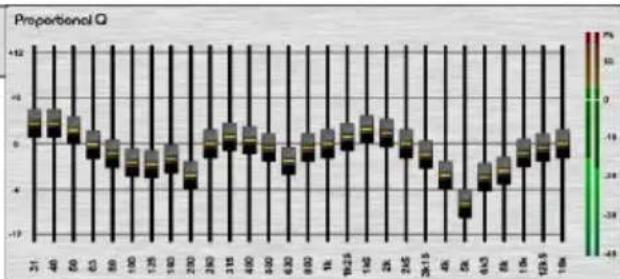
Proportional-Q -
Smooth wide Q which progressively narrows toward maximum cut or boost values.
bar
| X Value | Y Value | | ------- | ------- | | 31 | -8 | | 40 | -6 | | 50 | -4 | | 63 | -2 | | 80 | 0 | | 100 | 2 | | 125 | 4 | | 150 | 6 | | 200 | 8 | | 250 | 10 | | 315 | 12 | | 400 | 10 | | 500 | 8 | | 630 | 6 | | 800 | 4 | | 900 | 2 | | 1000 | 0 | | 1125 | -2 | | 1450 | -4 | | 2000 | -6 | | 2515 | -8 | | 40 | -10 | | 63 | -8 | | 8 | -6 | | 10 | -4 | | 12.5 | -2 | | 15 | 0 | | 17.5 | 2 | | 20.5 | 4 | | 25.5 | 6 | | 31.5 | 8 | | 40 | 10 | | 63 | 8 | | 8 | 6 | | 10 | 4 | | 12.5 | 2 | | 15 | 0 | | 17.5 | -2 | | 20.5 | -4 | | 25.5 | -6 | | 31.5 | -8 | | 40 | -10 | | 63 | -8 | | 8 | -6 | | 10 | -4 | | 12.5 | -2 | | 15 | 0 | | 17.5 | 2 | | 20.5 | 4 | | 25.5 | 6 | | 31.5 | 8 | | 40 | 10 | | 63 | 8 | | 8 | 6 | | 10 | 4 | | 12.5 | 2 | | 15 | 0 | | 17.5 | -2 | | 20.5 | -4 | | 25.5 |-6 | | 31.5 | -8 | | 40 | -10 | | 63 | -8 | | 8 | -6 | | 10 | -4 | | 12.5 | -2 | | 15 | 0 | | 17.5 | 2 | | 20.5 | 4 | | 25.5 |Hybrid GEQ –
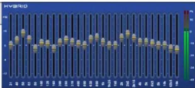
A combination of the Proportional-Q and Constant-Q units providing smooth boosts and clinical cuts.
bar
HYBRID | X-axis | Value | |---|---| | 31 | 0 | | 40 | 2 | | 50 | 4 | | 60 | 6 | | 70 | 8 | | 80 | 10 | | 90 | 12 | | 100 | 14 | | 110 | 16 | | 120 | 18 | | 130 | 20 | | 140 | 22 | | 150 | 24 | | 160 | 26 | | 170 | 28 | | 180 | 30 | | 190 | 32 | | 200 | 34 | | 210 | 36 | | 220 | 38 | | 230 | 40 | | 240 | 42 | | 250 | 44 | | 260 | 46 | | 270 | 48 | | 280 | 50 | | 290 | 52 | | 300 | 54 | | 310 | 56 | | 320 | 58 | | 330 | 60 | | 340 | 62 | | 350 | 64 | | 360 | 66 | | 370 | 68 | | 380 | 70 | | 390 | 72 | | 400 | 74 | | 410 | 76 | | 420 | 78 | | 430 | 80 | | 440 | 82 | | 450 | 84 | | 460 | 86 | | 470 | 88 | | 480 | 90 | | 490 | 92 | | 500 | 94 | | 510 | 96 | | 520 | 98 | | 530 | 100 | | 540 | 102 | | 550 | 104 | | 560 | 106 | | 570 | 108 | | 580 | 110 | | 590 | 112 | | 600 | 114 | | 610 | 116 | | 620 | 118 | | 630 | 120 | | 640 | 122 | | 650 | 124 | | 660 | 126 | | 670 | 128 | | 680 | 130 | | 690 | 132 | | 700 | 134 | | 710 | 136 | | 720 | 138 | | 730 | 140 | | 740 | 142 | | 750 | 144 | | 760 | 146 | | 770 | 148 | | 780 | 150 | | 790 | 152 | | 800 | 154 | | 810 | 156 | | 820 | 158 | | 830 | 160 | | 840 | 162 | | 850 | 164 | | 860 | 166 | | 870 | 168 | | 880 | 170 | | 890 | 172 | | 900 | 174 | | 910 | 176 | | 920 | 178 | | 930 | 180 | | 940 | 182 | | 950 | 184 | | 960 | 186 | | 970 | 188 | | 980 | 190 | | 990 | 192 | | ... (repeated) | ... (repeated) for the last row. The values in the table represent the magnitude of the variable 'Value' on the y-axis. The color intensity of the bars is based on the 'Color' legend, ranging from -4.5 to +4.5. The x-axis is labeled with the same numeric row 'X'.Digi GEQ -
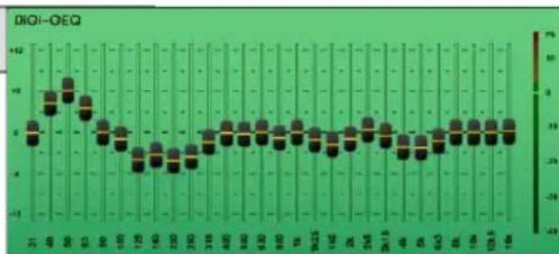
Optimised gain and width to minimise frequency band interaction.
7.7 PEQ
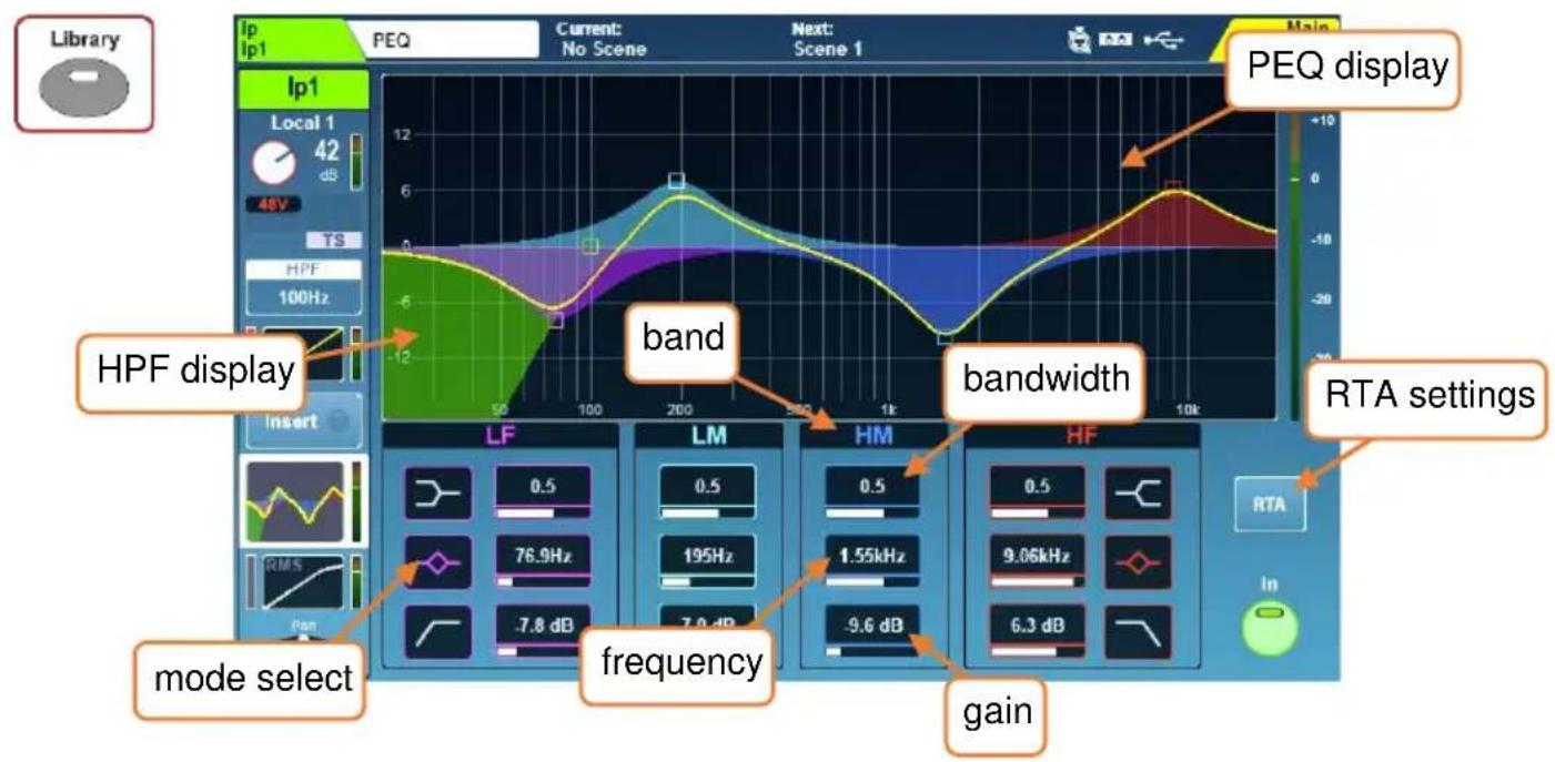
The PEQ can be switched in or out using the physical 'In' key on the surface or with the on-screen 'In' button.
- The 4-bands of the parametric EQ are labelled to match the physical EQ section on the surface.
- To use the dedicated physical EQ controls, select a band, and use the gain, bandwidth and frequency rotaries to adjust. To adjust on-screen, touch a parameter and use the touchscreen rotary, or touch and drag points on the graph.
The frequency band selected on the surface can be set to follow the on-screen selection in Surface Preferences.
- Touch the relevant icon to switch between the shelf, bell and filter modes for LF and HF bands.
- When the PEQ is active, the graphical display is brightly coloured, when inactive, it is greyed out.
LF Mode = Shelf, Bell, HPF HF Mode = Shelf, Bell, LPF Frequency (all modes) = 20Hz to 20kHz Width (parametric) = 1.5 octave to 1/9^th octave Gain (parametric, shelf) = -15dB to +15dB
- Touch the ‘RTA’ button to view and adjust the RTA overlay settings. Full details on the PEQ RTA are in the RTA section of this guide.
7.8 Compressor
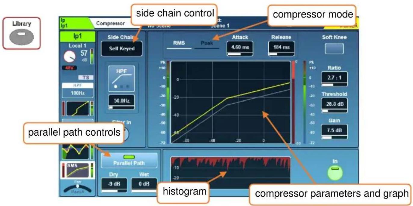
Switch the Compressor in or out using either the on-screen 'In' button or the physical Compressor 'In' key (to the left of the dedicated Compressor threshold rotary).
Side Chain –
- Select either 'Self Keyed' or side chain the compressor from another channel.
When using another channel as a side chain input, the signal is sourced after all channel processing, post millisecond channel delay.
- Touch the filter type to switch between HPF/BPF/LPF modes.
- Touch the frequency to select, then adjust using the touchscreen rotary.
HPF Frequency = 20Hz to 5kHz
BPF Frequency = 120Hz to 10kHz
LPF Frequency = 120Hz to 20kHz
Compressor Mode –
There are two detection modes in the standard compressor, RMS (average) and Peak. Touch either mode to toggle between them. The active mode is displayed in white.
Soft Knee -
Touch this button to switch on the soft knee setting. This enables a variable ratio which smooths the behaviour of compression around the threshold (this is also displayed on the graph).
Parameters –
- Adjust parameters by touching to select and then using the touchscreen rotary.
Attack = 30μs to 300ms
Release= 50ms to 2secs
Ratio = 1:1 (no compression) to Infinity (limiting)
Threshold = -46dB to +18dB
Gain (make-up gain) = 0dB to +18dB
Graph -
- The graph displays input/threshold on the x-axis and output level on the y-axis to give a visual representation of parameter settings.
- The side chain input level is shown on the meter to the left of the graph.
- Compression (signal reduction) from 0dB to -30dB is shown on the meter to the immediate right of the graph. When the compressor is switched in, this is red, otherwise it is white.
- The post-compressor (output) level is shown to the right of the signal reduction.
Parallel Compression –
This allows you to blend the compressed signal with the uncompressed signal. Due to the XCVI core, these signals are coherent, and no comb filtering is introduced.
- Touch the 'Parallel Path' button to switch in or out.
- Touch the Dry/Wet values and adjust using the touchscreen rotary.
Dry/Wet individual level = -infinity to 0dB
Histogram –
The histogram shows the previous 12 seconds of compressor activity, moving from right to left. As with the level reduction meter, when the compressor is in, the level reduction (depth) is shown in red, and when out is shown in white/grey.
Ducker Mode –
‘Ducker Mode’ is available as an option in the Compressor Library. This is a special compressor mode that reduces channel level based on signal from another channel (using the side chain input). Ducking is commonly used on a background music channel with the side chain fed from an announcement microphone.
DEEP Compressors – Optional ‘Add-on’ compressors, modelled on classic hardware units with unique tonal and behavioural characteristics.
Once DEEP compressor models have been added to an SQ, they can be used in place of the RMS/Peak compressor on any input or mix channel.
Information on how to add models can be found in the Add-ons section of this guide.
- Press the 'Library' key to see the Compressor Library.
- Different compressor models can be recalled from the 'Factory' library.
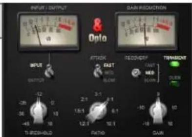
Opto -
The best characteristics from a range of optical compressors combined into one smooth sounding unit.
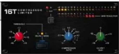
16T-
Tight and punchy VCA-based RMS compressor, with natural sounding gain reduction.
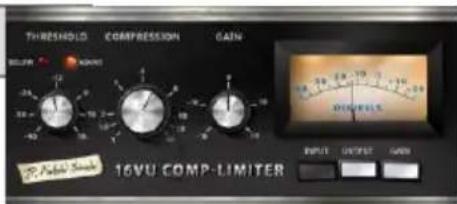
16VU-
The classic VCA-based RMS compressor. Musically enhances low-mid frequencies when driven.
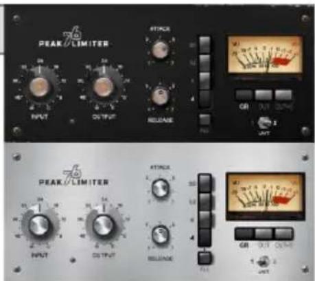
Peak Limiter 76 –
Two versions of the renowned FET levelling amplifier. One vintage, one more modern, both with all-button mode.
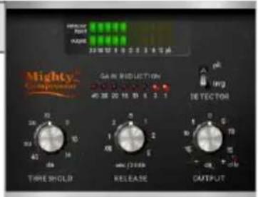
Mighty -
Transistor array compressor that features a unique attack sound. Capable of massive gain reduction with low distortion.
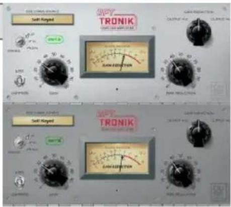
OptTronik –
Two versions of the legendary electro-optical levelling amplifier. Smooth and musical compression.
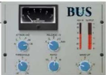
Bus -
The most well-known VCA compressor for sonic cohesion of mixes and program material.
8. Routing
Press any 'Sel' key to select a channel, then press the 'Routing' screen key to display the routing 'bank view'. This shows an overview of 8 channels at once, with the selected channel highlighted.
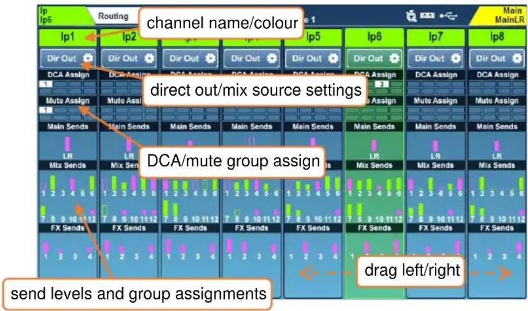
If a channel is assigned to a DCA or Mute group, this is shown with a filled, numbered icon.
Send levels for Input and Group channels are displayed for Main/LR, Aux sends and FX sends. These are displayed as a filled bar if assigned, and an outline if unassigned. The bar is coloured pink for post-fade and green for pre-fade.
If a mix has been configured as a group, and a channel is assigned to the group, this is shown with a pink circle.
The 8 channels shown will automatically adjust if a different channel is selected, though you can also drag left or right to see other channels in the layer.
- Touch a channel name to change the name and colour.
- Touch the 'Dir Out' button on input channels to see direct out settings.
- Touch the DCA/Mute Assign 'blocks' to see assignments.
- Touch anywhere in the Main/Mix/FX/Matrix Send levels to see detailed send information for the channel.
- Touch anywhere in the Matrix Sources to see all sources for that Matrix.
- Touch the list of members on a DCA channel to view and assign or unassign the members of that DCA.
DCA channels display a list of up to 28 'members'. If there are more members than this, then '…' will appear at the bottom of the list.
8.1 Direct Out
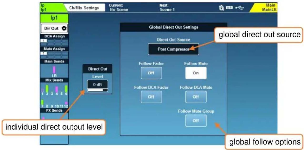
Touch the 'Dir Out' button on any input channel.
This screen shows the direct output level for the selected channel, as well as the global direct out settings which affect all channels. The currently selected channel is displayed on the left.
- Touch the level value and adjust using the touchscreen rotary, this is adjusted individually on each channel.
Direct out level = -inf to +10dB
- Choose whether direct out signals are affected by faders or mutes by touching the on-screen buttons.
- Select the channel ‘tap off’ point by touching the ‘Direct Out Source’ value. Each source point is presented in order, and is affected by all preceding processing that is switched in.
Post Preamp = signal is affected only by the preamp gain.
Post HPF = signal is also affected by the high pass filter.
Post Gate = signal is also affected by the gate.
Post Insert Return = signal is also affected by the insert.
Post PEQ = signal is also affected by PEQ.
Post Comp = signal is also affected by compressor.
Post Delay = signal is affected by all channel processing including ms delay.
8.2 Mix Send and Balance Settings
Mix channels have different buttons in place of the 'Dir Out' button found on the input channels, touch this to see the following options.
Main – ('Main Snd')
- Touch the ‘Output Bal’ value and adjust using the touchscreen rotary to adjust the output balance.
Group – ('Group')
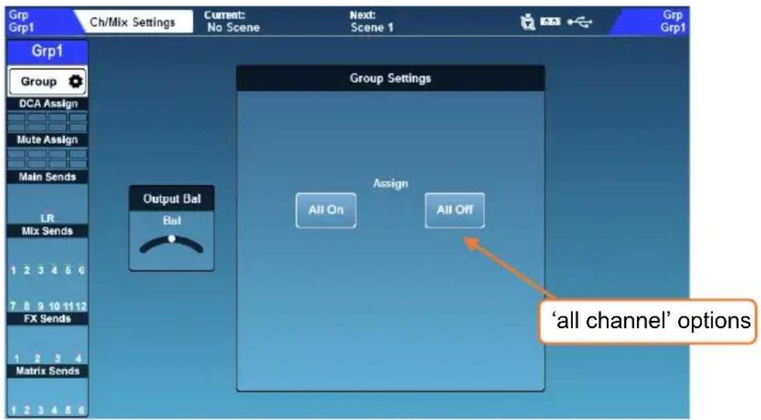
- Touch the 'Output Bal' value and adjust using the touchscreen rotary to adjust the output balance.
- Touch 'All On' or 'All Off' button to assign or unassign all channels to the group.
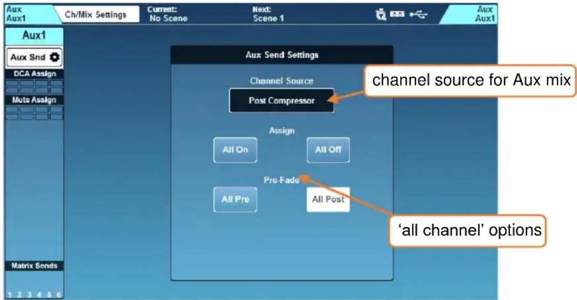
- Touch the ‘Channel Source’ value to choose the where the aux takes channel signal from. Each source point is presented in order, and is affected by all preceding processing that is switched in.
Post Preamp = signal is affected only by the preamp gain.
Post EQ = signal is also affected by HPF, gate, insert and PEQ.
Post Compressor = signal is also affected by compressor.
Post Delay/AMM = signal is affected by all channel processing.
See the Block Diagrams section for a visual representation of signal paths.
- Touch 'All On' or 'All Off' button to assign or unassign all channels to the aux.
- Touch 'All Pre' or 'All Post' button to set all channel sends to pre-fade or post-fade.
FX - ('FX Snd')
- Touch the ‘Channel Source’ value to choose the where the FX send bus takes channel signal from. Each source point is presented in order, and is affected by all preceding processing that is switched in.
Post Preamp = signal is affected only by the preamp gain.
Post EQ = signal is also affected by HPF, gate, insert and PEQ.
Post Compressor = signal is also affected by compressor.
Post Delay/AMM = signal is affected by all channel processing.
- Touch 'All On' or 'All Off' button to assign or unassign all channels to the FX bus.
- Touch 'All Pre' or 'All Post' button to set all channel sends to pre-fade or post-fade.
8.3 DCA/Mute Groups
Touch the DCA/Mute Assign block to show assignments for the selected channel.
Digitally Controlled Amplifiers (DCA's) control the send levels and mutes of multiple channels with a single fader and mute key.
Mute groups are used to mute multiple channels using a single SoftKey.
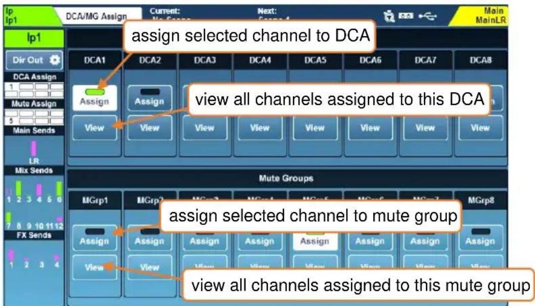
- Touch 'Assign' buttons to assign or unassign the selected channel to DCA's or Mute Groups.
- Touch the 'View' buttons to see all channels currently assigned to that DCA or Mute Group at once.
- Touch and drag up and down in a 'View' window to see all channels.
- Channels can be assigned or unassigned by touching assignment buttons.
- Touch the DCA/Mute Assign 'blocks' to return to the selected channel assignments view.
In both ‘Processing’ and ‘Routing’ screens, DCA channels display a list of up to 28 channel ‘Members’ (channels assigned to that DCA). If there are more members than this, then ‘...’ will appear at the bottom of the list.
- Touch anywhere on a DCA member list to view and assign or unassign channels.
DCA's are for control only, and do not sum or carry signal, and therefore do not have any processing or metering functionality.
i Pressing the PAFL key on a DCA fader strip is the equivalent of using additive PAFL on every member of the DCA. When engaged, PAFL keys of the DCA members will flash.
When muting DCA's or Mute Groups, the mute keys of the assigned channels will flash. If a channel is also muted independently, the duration of illumination will change to indicate this.
The ‘DCA Spill’ feature allows you to ‘spill’ DCA members across the channel strips. See the DCA Spill section for more information.
8.4 Send Levels and Mix Assignments
flowchart
graph TD
    A["MainL R"] --> B["Post"]
    B --> C["Pre"]
    C --> D["Pre"]
    D --> E["Post"]
    E --> F["Pre"]
    F --> G["Pre"]
    G --> H["On"]
    H --> I["On"]
    I --> J["On"]
    J --> K["On"]
    K --> L["On"]
    L --> M["On"]
    M --> N["On"]
    N --> O["On"]
    O --> P["On"]
    P --> Q["On"]
    Q --> R["On"]
    R --> S["On"]
    S --> T["On"]
    T --> U["On"]
    U --> V["On"]
    V --> W["On"]
    W --> X["On"]
    X --> Y["On"]
    Y --> Z["On"]
    Z --> AA["On"]
    AA --> AB["On"]
    AB --> AC["On"]
    AC --> AD["On"]
    AD --> AE["On"]
    AE --> AF["On"]
    AF --> AG["On"]
    AG --> AH["On"]
    AH --> AI["On"]
    AI --> AJ["On"]
    AJ --> AK["On"]
    AK --> AL["On"]
    AL --> AM["On"]
    AM --> AN["On"]
    AN --> AO["On"]
    AO --> AP["On"]
    AP --> AQ["On"]
    AQ --> AR["On"]
    AR --> AS["On"]
    AS --> AT["On"]
    AT --> AU["On"]
    AU --> AV["On"]
    AV --> AW["On"]
    AW --> AX["On"]
    AX --> AY["On"]
    AY --> AZ["On"]
    AZ --> BA["On"]
    BA --> BB["On"]
    BB --> BC["On"]
    BC --> BD["On"]
    BD --> BE["On"]
    BE --> BF["On"]
    BF --> BG["On"]
    BG --> BH["On"]
    BH --> BI["On"]
    BI --> BJ["On"]
    BJ --> BK["On"]
    BK --> BL["On"]
    BL --> BM["On"]
    BM --> BN["On"]
    BN --> BO["On"]
    BO --> BP["On"]
    BP --> BQ["On"]
    BQ --> BR["On"]
    BR --> BS["On"]
    BS --> BT["On"]
    BT --> BU["On"]
    BU --> BV["On"]
    BV --> BW["On"]
    BW --> BX["On"]
    BX --> BY["On"]
    BY --> BZ["ON"]
    BZ --> CA["ON"]
    CA --> CB["ON"]
    CB --> CC["ON"]
    CC --> CD["ON"]
    CD --> CE["ON"]
    CE --> CF["ON"]
    CF --> CG["ON"]
    CG --> CH["ON"]
    CH --> CI["ON"]
    CI --> CJ["ON"]
    CJ --> CK["ON"]
    CK --> CL["ON"]
    CL --> CM["ON"]
    CM --> CN["ON"]
    CN --> CO["ON"]
    CO --> CP["ON"]
    CP --> CQ["ON"]
    CQ --> CR["ON"]
    CR --> CS["ON"]
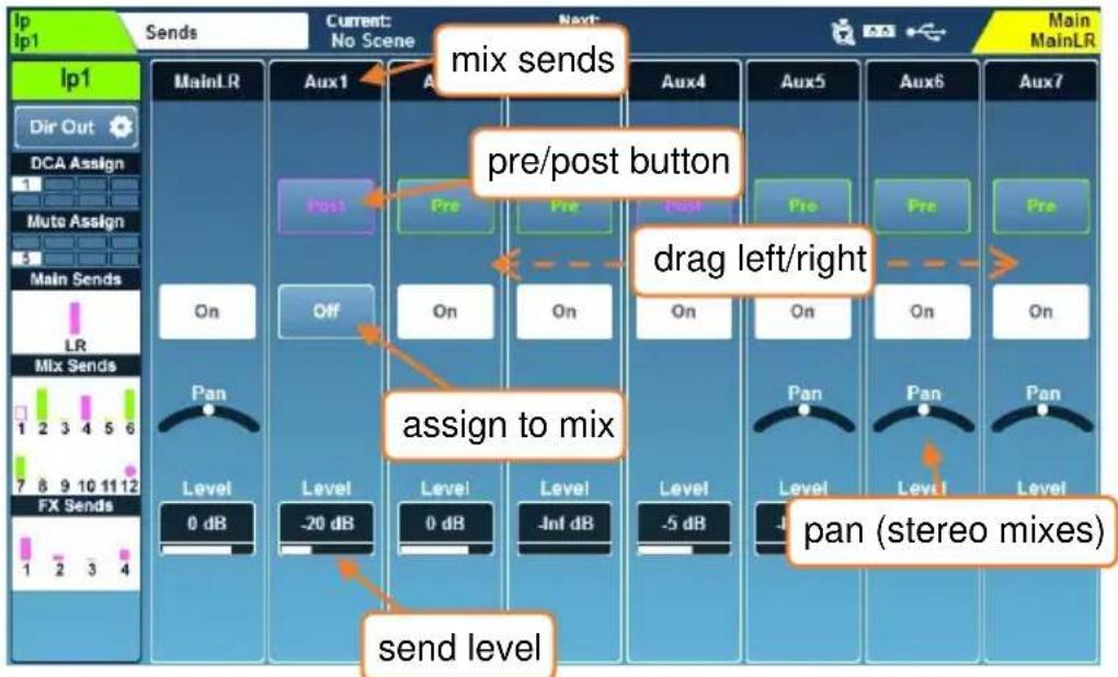
This screen displays all sends and mix assignments for the selected channel.
- Touch and drag left or right to view all mixes and sends.
- Touch an 'On/Off' button to assign or unassign the channel to a mix/send or matrix.
- Touch a 'Pre/Post' button to set a send to either Pre-fade or Post-fade.
- Touch a 'Pan/Bal' control and use the touchscreen rotary to set the pan or balance for a send.
- Touch a 'Level' value to adjust the send level to a mix using the touchscreen rotary.
① Holding the ‘Assign’ key on the mixer surface and pressing the ‘Sel’ key of a channel will assign or unassign that channel from the currently selected mix.
① Holding the 'Assign' key on the mixer surface and pressing the 'Sel' key of a mix will assign or unassign all channels to that mix.
Holding the 'Pre Fade' key on the mixer surface and pressing the 'Sel' key of a channel toggles channel send to the currently selected mix between pre and post fade send.
① Holding the 'Pre Fade' key on the mixer surface and pressing the 'Sel' key of a mix toggles all channel sends between pre and post fade send.
8.5 CH to All Mix key
Pressing and holding the momentary ‘CH to All Mix’ key displays all send levels for the currently selected channel on the fader strips. If the selected channel is a mix, then the send levels to matrices will be shown.
The CH to All Mix key can be held at the same time as the 'Assign' or 'Pre Fade' keys to quickly change routing options to all mixes for the selected channel.
8.6 Matrices
The SQ features 3 stereo matrix buses which can be split to provide up to 6 mono matrices. These can be fed by any combination of SQ mixes and routed to any available output socket for applications including:
- Recording – a single mix or combination of mixes can be recorded with additional mix processing and level control.
- Extra speakers – a matrix can be used to send a duplicate of single mix (often the LR mix) with extra processing and/or added delay. This is useful for ‘fill’ speakers or to time align ancillary speakers.
- Feeding subwoofers – by routing the main LR mix (Post-Fade) to a matrix and using this to feed subwoofers, the entire system level can be controlled by the LR master send, but the subwoofers have additional processing and level control.
There are three methods for sending a mix to a matrix.
1) The matrix sends from a mix are shown in the send levels and assignments screen when a mix is selected.
2) The matrix sources are shown in the send levels and assignments screen when a matrix is selected.
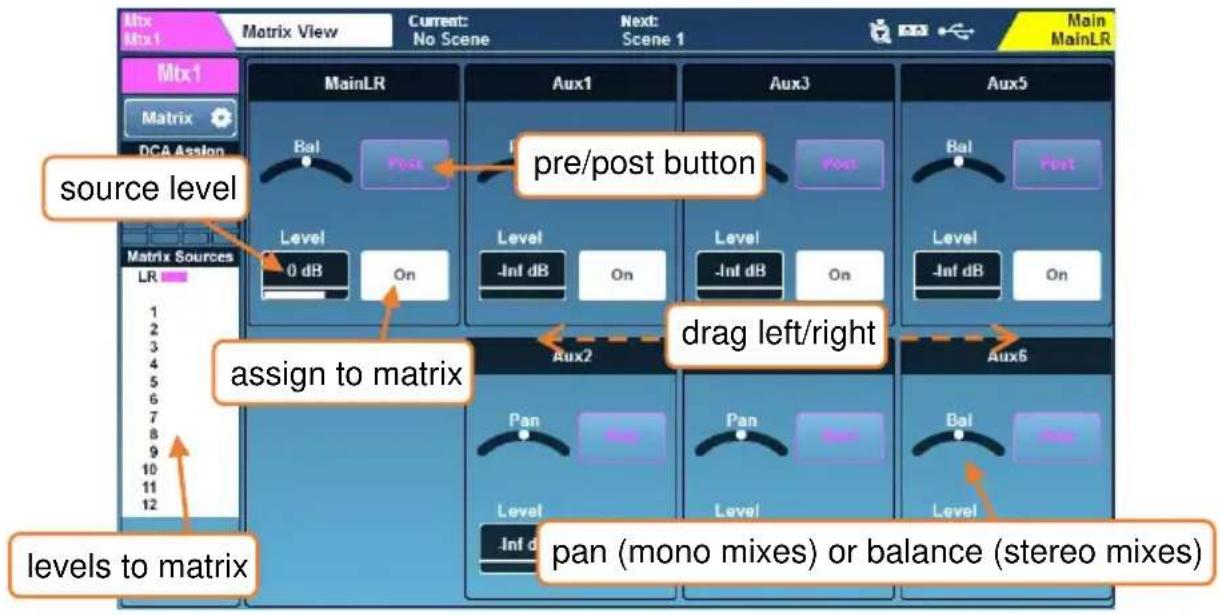
3) The matrix sends are shown on faders when a mix channel is selected and the momentary 'CH to All Mix' key is pressed and held on the surface of the SQ.
For information on setting any mix to mono, see Input/Mix stereo assign.
9. Metering
9.1 PAFL LED Meter
The 12 segment LED metering on the surface of the SQ to the right of the touchscreen displays level metering for the PAFL bus, so will always show metering for what is being sent to the headphone output.
By default, with no PAFL keys active, this displays the main LR mix level.
The PAFL LED indicator below the 12 segment LED illuminates when a PAFL routing key or button is active anywhere in the mixer.
9.2 Input/FX/Mix/USB Meters
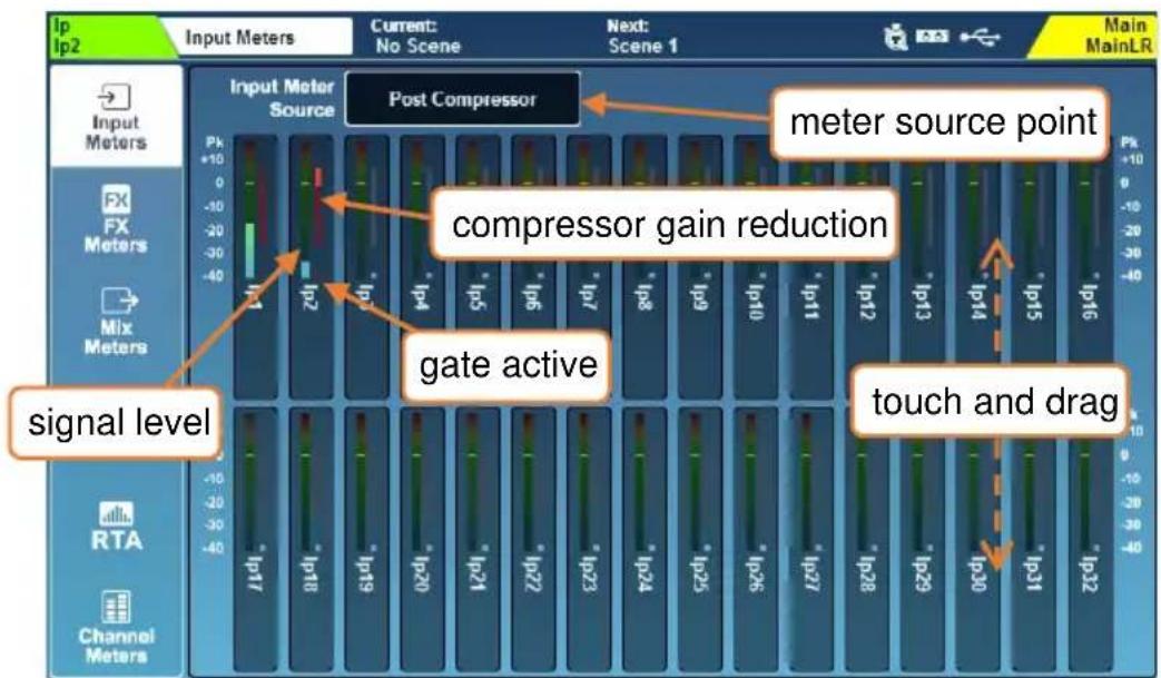
The first four tabs on the ‘Meters’ screen show ‘Input Meters’, ‘FX Meters’, ‘Mix Meters’ and ‘USB Meters’.
- The main coloured meters display levels from -40dB to +10dB.
- Gain reduction meters show level reduction from 0dB to -30dB, this is red/bright red when the compressor is switched in and grey/white when it is switched out.
- The gate active indicators are red/bright red when the gate is switched in and grey/white when the gate is switched out.
Input Meters –
Touch and drag up and down to view all channels in the Input Meters screen.
Touch the Input Meter Source to choose the metering point for all input channels.
Post Preamp = meter is sourced directly after the preamp.
Post EQ = meter is sourced directly after the PEQ.
Post Compressor = meter is sourced directly after the compressor.
Post Delay/AMM = meter is sourced after all processing.
i Note that meter source settings also affect the Chromatic Channel Metering.
FX Meters –
Includes the dedicated FX Send busses and stereo FX Return channels.
Mix Meters –
Touch the Mix Meter Source to choose the metering point for mix channels.
Post Bus + Ext In = meter is sourced after all channels have been summed, including the mix external input.
Post GEQ = meter is sourced directly after the GEQ.
Post PEQ = meter is sourced directly after the PEQ.
Post Compressor = meter is sourced directly after the compressor.
Post Delay/Fader = meter is sourced after all processing and fader.
i Note that meter source settings also affect the Chromatic Channel Metering.
USB Meters –
- 'USB Inputs' show levels on the USB stream coming into the SQ, and labels these with the highest numbered channel or socket they have been patched to.
- 'USB Inputs' show either the meters coming from USB-B (SQ-Drive not in use for playback) or those from SQ-Drive (SQ-Drive is being used for playback).
- 'USB Outputs' shows the level and source of signals being sent to USB and SQ-Drive.
USB Meters always display the maximum 32 channels of inputs and outputs but only the first 16 apply for SQ-Drive when USB sample rate is set to 96kHz.
9.3 Chromatic Channel Metering
The Chromatic Channel Metering displays the information of a high-resolution meter in the space of a single LED. It can depict a much greater range of levels than a traditional meter and behaviour is customisable in the ‘Channel Meters’ tab.
The Chromatic Channel Meter source matches the meter source point selected for Input and Mix Meters.
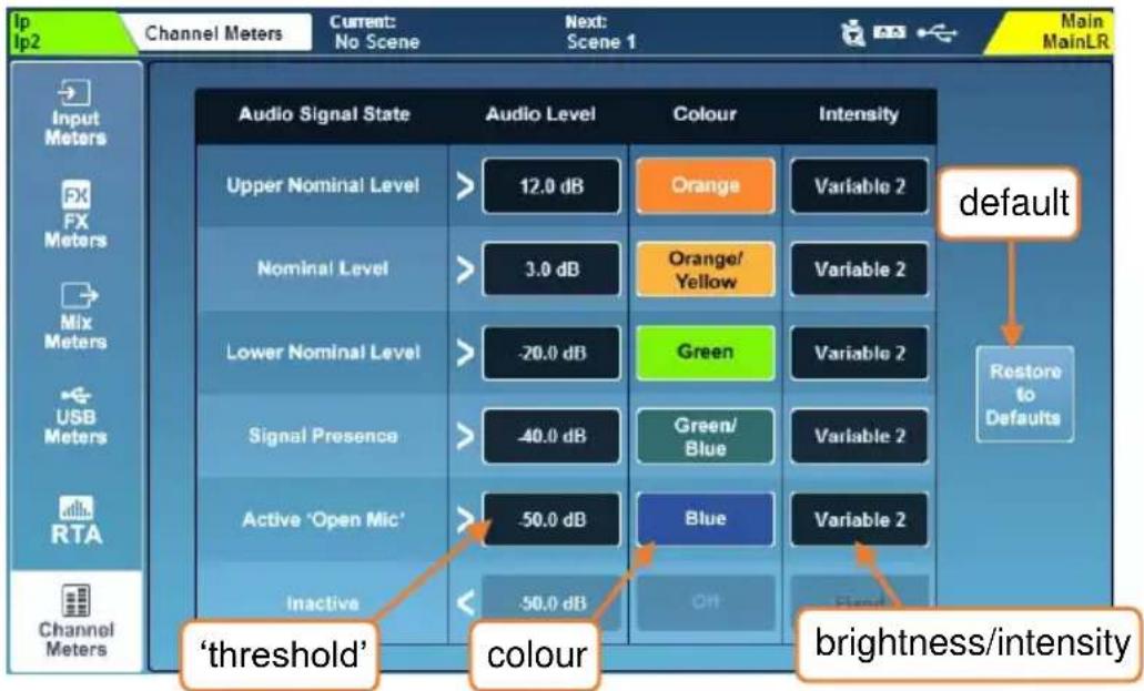
- Touch an 'Audio Level' value and adjust using the touchscreen rotary.
i 'Audio Level' values are bound by the level setting of states above and below.
- Touch a colour for an ‘Audio Signal State’ and use the touchscreen rotary to adjust the colour/s for this level range.
Colours = White, Red, Orange, Orange/Yellow, Yellow, Green, Green/Blue, Blue, Blue/Red, Off.
- Touch the 'Intensity' value to choose the behaviour of the meters.
Fixed = meter switches instantly between states.
Variable 1 = Meter changes close to the endpoints of its range.
Variable 2 = Meter changes across the whole range.
- Touch the 'Restore to Defaults' button to restore settings:
| Upper Nominal | > | +12.0dB | Orange | Variable 2 |
| Nominal | > | +3.0dB | Orange/Yellow | Variable 2 |
| Lower Nominal | > | -20.0dB | Green | Variable 2 |
| Signal Presence | > | -40.0dB | Green/Blue | Variable 2 |
| Active ‘Open Mic’ | > | -50.0dB | Blue | Variable 2 |
| Inactive | < | N/A | N/A | N/A |
9.4 RTA's
There are two Real Time Analysers in the SQ. One is shown in the Meters screen (the 'Meters RTA') and the other can be displayed in PEQ or GEQ processing screens and/or shown using Chromatic Channel Metering when in GEQ 'Fader Flip' mode (the 'Channel RTA').
RTA – Meters Screen –
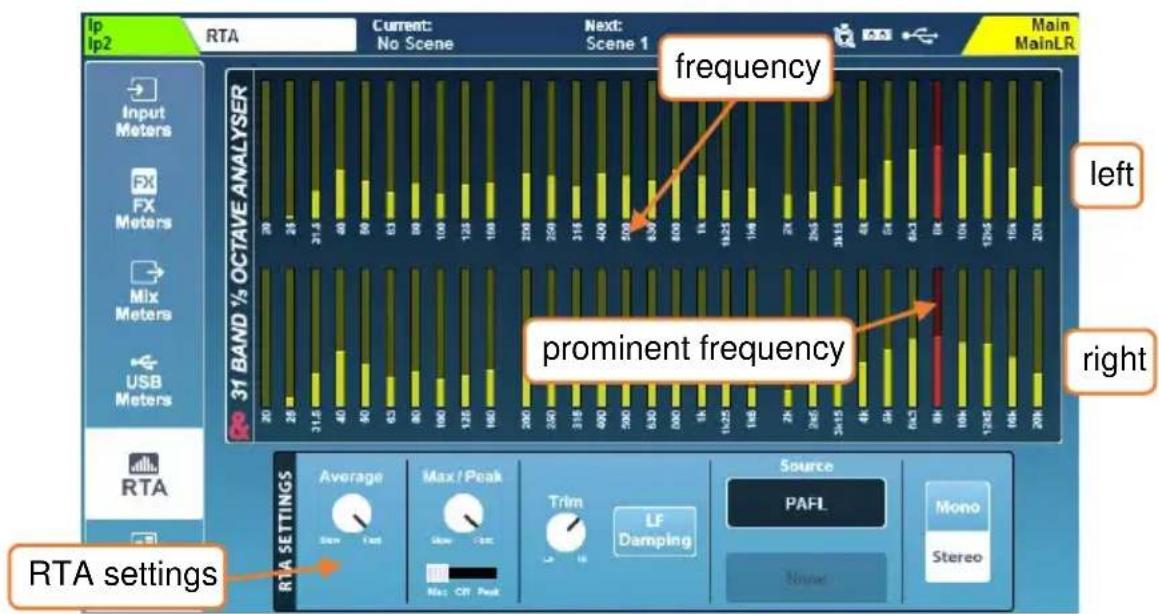
By default, the Meters screen ‘RTA Source’ is set to ‘PAFL’ to match what is being sent to the headphone output and 12 segment LED meter. The source can also be switched to a specific fixed channel if desired.
• The most prominent frequency is shown in red.
• Mono mode displays L+R.
- Touch switches or values to select from options or make adjusts using the touchscreen rotary.
Source = PAFL or Fixed Channel.
Fixed Channel = Any input or mix channel.
Mono/Stereo = Stereo 31 band 1/3^rd Octave or Mono 61 band 1/6^th Octave.
Trim = Raise or lower the metering level.
Average Slow to Fast = Adjusts the effective number of samples used by the average (bar) meters.
Max/Peak Slow to Fast = Adjusts the effective number of samples used by the max/peak indicators.
Max-Off-Peak = Max displays the higher of either average or peak, Peak always displays peak (which may be lower than the average meters).
LF Damping = When enabled, response is gradually dampened towards the lowest frequency band, to better represent LF output energy.
RTA – PEQ Screen –
The 61 band PEQ RTA uses automatic gain control (pre-trim) to display useful relative levels of frequencies on the PEQ graph. By default, it is sourced from the selected channel and is shown on all input and mix channels.
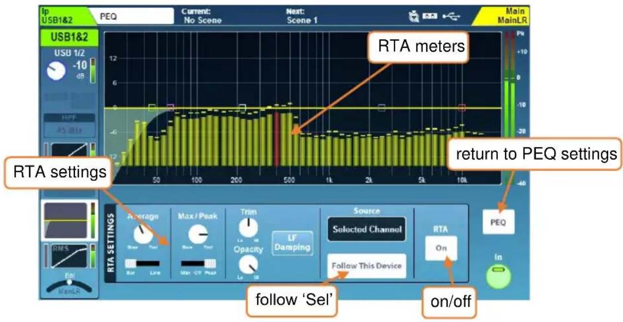
The average meters for the PEQ RTA can either be displayed as bars, with each meter's centre aligned with the frequency it represents, or as a line.
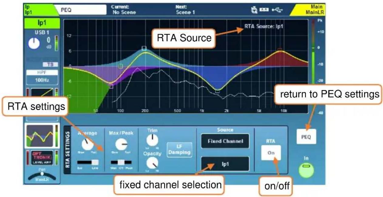
- If the RTA Source is using the ‘Fixed Channel’ option and is different to the currently selected channel, the RTA Source channel is displayed at the top right.
- If the RTA for a different channel is displayed because it has been selected by another device (e.g. SQ-MixPad), the RTA source is shown at the top right with a ‘!’ prefix and the RTA meters will be greyed out.
- When displaying bars, the most prominent frequency is shown in red.
- Stereo sources display metering for L+R.
- Touch switches or values to select from options or make adjusts using the touchscreen rotary.
Source = Selected Channel or Fixed Channel.
Follow this device = When enabled, selecting a channel on this device will also select the Channel RTA source
Fixed Channel selection = Any input or mix channel.
Trim = Raise or lower the metering level.
Opacity = Adjusts the opacity of the RTA metering
Average Slow to Fast = Adjusts the effective number of samples used by the average (bar or line) meters.
Bar-Line = Display multiple bars or a single line.
Max/Peak Slow to Fast = Adjusts the effective number of samples used by the max/peak indicators.
Max-Off-Peak = Max displays the higher of either average or peak, Peak always displays peak (which may be lower than the average meters).
LF Damping = When enabled, response is gradually dampened towards the lowest frequency band, to better represent LF output energy.
- Touch the 'PEQ' button to return to the PEQ settings.
RTA - GEQ Screen -
The 28 band GEQ RTA uses automatic gain control (pre-trim) to display useful relative levels of frequencies for each band of the Graphic EQ. By default, it is sourced from the selected mix channel.
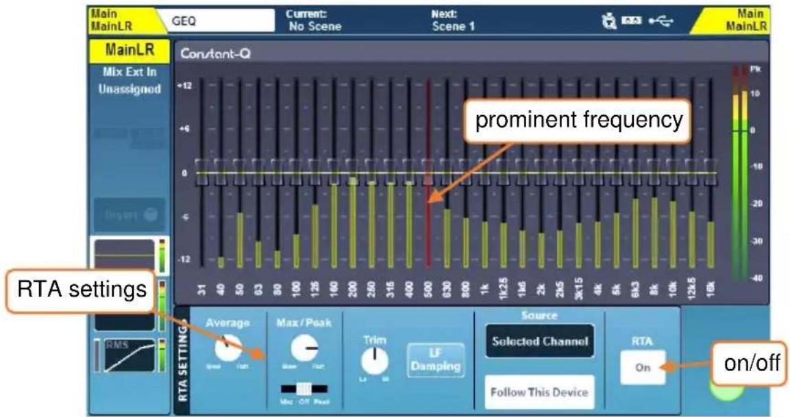
- If the RTA for a different channel is being displayed through use of the 'Fixed Channel' option, the RTA source is shown at the top right.
- If the RTA for a different channel is displayed because it has been selected by SQ-MixPad, the RTA source is shown at the top right with a ‘!’ prefix and the RTA meters will not be visible.
- The most prominent frequency is shown in red.
- Stereo sources display metering for L+R.
Source = Selected Channel or Fixed Channel.
Follow this device = When enabled, selecting a channel on this device will also select the Channel RTA source
Fixed Channel selection = Any input or mix channel.
Trim = Raise or lower the metering level.
Opacity = Adjusts the opacity of the RTA metering
Average Slow to Fast = Adjusts the effective number of samples used by the average (bar) meters.
Max/Peak Slow to Fast = Adjusts the effective number of samples used by the max/peak indicators.
Max-Off-Peak = Max displays the higher of either average or peak, Peak always displays peak (which may be lower than the average meters).
LF Damping = When enabled, response is gradually dampened towards the lowest frequency band, to better represent LF output energy.
RTA - GEQ 'Fader Flip' -
When in GEQ ‘Fader Flip’ mode, if the PEQ/GEQ RTA is displaying the currently selected mix (i.e. the mix being controlled by the faders) then the Chromatic Channel Meters will display the level of each frequency band above the fader that controls it. The most prominent frequency is also displayed using the Pk LED's.
If the PEQ/GEQ RTA is displaying a different channel to the one selected, the Chromatic Channel Meters and Pk LED's will not illuminate.
9.5 Other Metering
- Detailed metering is displayed after each processing ‘block’ and is particularly useful for checking gain staging.
- SQ-Drive metering on the multitrack screen displays either the signal being sent to, or the signal returning from the SQ-Drive, depending on state (recording/playback).
Peak and multi-point peak metering –
As long as a peaking channel has been assigned to a channel strip, there is always visibility of any peaking on the SQ surface to allow potentially destructive peaking anywhere within a channel to be found as follows:
- If a channel is peaking on a channel strip on an inactive layer, the layer selection key will illuminate red.
- With the layer selected, the red peak (Pk) LED on each channel strip uses multi-point sensing to display peaking anywhere in that channel's processing path.
- By selecting the channel, the red peak (Pk) LED's next to dedicated processing controls (Preamp, PEQ, GEQ, Compressor) will illuminate when signal reaches - 3dBFS at the meter directly following that processing 'block'. 0dBFS is absolute maximum, so the Pk LED indicates the signal is close to digital clipping at that point.
10. FX Engines
There are 8 RackFX engines in the SQ which can be used for any available FX type, meaning any combination of 8 types can be used at any one time.
Each unit has its own dedicated stereo return with PEQ for routing using Mix -> Return, or a unit can be inserted directly into any input or mix processing channel.
FX units can be controlled from either the FX screen, or from the processing screen with an FX Send or Return channel selected.
To always show the relevant FX unit when viewing the FX screen, enable the 'FX Screen Follow Sel' option in Surface Preferences.
10.1 Loading Units and Presets
Pressing the 'FX' screen key displays the front/rear of the currently selected FX engine, with other loaded FX units and any empty slots on the left of the screen.
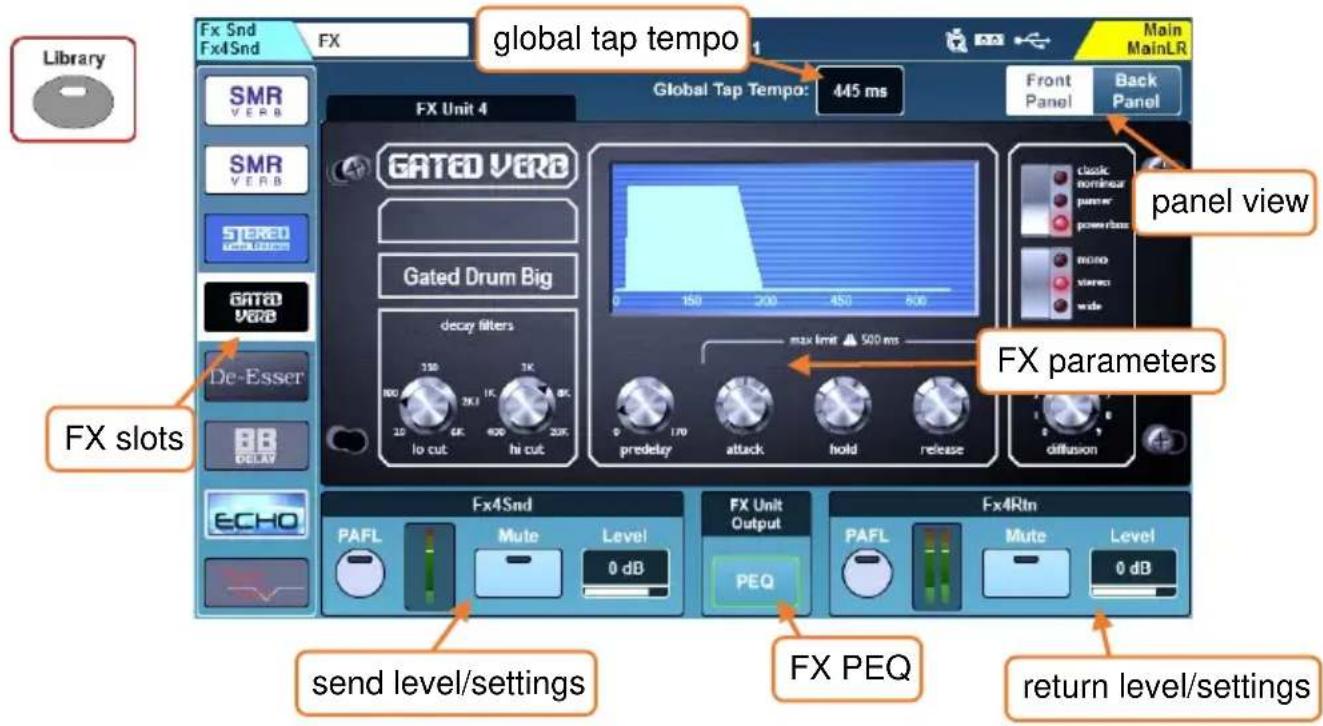
- Select the slot you wish to use.
- Press the 'Library' key on the surface to open the FX Library.
- Select an FX type, then a 'Factory' preset. Different presets use different FX types, so to load a different FX type, recall a preset which uses it.
- Touch the 'Recall' button to recall the preset and FX type.
User presets can be stored and recalled to and from the 'User' section of the FX library.
By default, the first four FX engine slots have been populated with useful FX presets, but all 8 slots are freely assignable.
10.2 Adjusting Parameters
Each FX type has a different set of parameters, but all work in the same way.
- Touch any buttons to switch between modes or states.
- Touch parameter controls or values and use the touchscreen rotary to adjust.
The SMR FX type is a special case – there are 4 different reverb algorithms available and pressing the 'Expert' button will give access to much more in-depth control for fine tuning of each. In this mode, cycle through all available parameter settings using the 'Page' button.
10.3 Using FX Buses and Returns
The SQ has four FX send buses which are routed to the inputs of the first four FX engine slots by default and when using Mix -> Return with 'FX Send' selected.
These buses can be used in the same way as any of the mix buses:
- Press an FX key from 1 to 4 to show and adjust the send levels on faders for each fader strip to that FX bus. Or with a channel selected, hold the 'CH to All Mix' key to show and adjust all FX bus sends for the selected channel (along with all other sends).
- The master FX send level is controlled with the Master channel (when in ‘Mix Master’ mode and displaying the FX sends on faders).
The output from the FX unit is returned to the matching FX return channel for each FX engine slot. (i.e. the 'FX Unit 1' output is routed to 'Fx1Rtn').
- All FX return channels are stereo and feature a PEQ.
- FX Returns are assigned and sent to mixes in the same way as any input channel.
The signal path is:
Input/Group/FXRet channel → FX Send → FX Unit → FX Return → Mix channel
Which gives full control over the amount of each channel being sent to each FX unit, as well as the amount of ‘wet’ affected sound being sent to each mix.
FX return channels can be assigned to fader strips but will not be visible unless they are routed to from the output of the FX engine (i.e. set as 'Mix -> Return' on the back panel).
10.4 Sending to FX from Other Sources
Mix->Return – As well as sending using the four FX buses, you can send to the FX engines using mixes, allowing you to send to any of the 8 FX engines using ‘sends on faders’. This routing type can also be used with channel direct outs.
For any adjustment to routing first press the 'Back Panel' button at the top right of the FX screen.
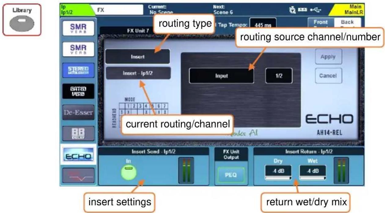
1) Set the routing type to 'Mix -> Return'.
2) Touch the routing source value to select a source.
Sources = FX Send, Group, Aux, Main, Matrix, Ip Direct Out
3) Touch the channel value and adjust using the touchscreen rotary.
4) Touch the 'Apply' button to apply changes.
Inserts – You can insert FX engines into individual channels or mixes. This automatically sets up and uses the insert point of the channel.
1) Set the routing type to 'Insert'.
2) Touch the routing source value to select a source.
Sources = Input, Group, Aux, Main, Matrix
3) Touch the channel value and adjust using the touchscreen rotary.
4) Touch the 'Apply' button to apply changes.
Typically, signal processors such as multiband compressors and de-essers are used inserted in this way.
10.5 FX Levels and PEQ
Mix->Return -
When routed as ‘Mix -> Return’, the PAFL, Mute and Level settings for the currently selected FX engine slot are displayed at the bottom of the screen for both the FX send and FX return.
- Touch buttons to PAFL or mute channels.
- Touch values and adjust using the touchscreen rotary.
Inserts –
When an FX engine is being used as an insert, the insert 'In' button and return wet/dry mix values are displayed.
- Touch the 'In' button to switch the insert in or out.
- Touch either wet or dry values to adjust the blend of the dry (unprocessed) signal with the wet (processed) signal.
Dry/Wet individual level = -infinity to 0dB
PEQ -
Press the PEQ button at the bottom centre of the screen to view and adjust the PEQ which affects the output of the FX. This works in exactly the same way as any channel processing PEQ.
All level and PEQ settings, presented on the FX screen for convenience, duplicate control available elsewhere in the mixer. The PEQ for example, is the same PEQ that can be accessed when selecting FX return channels in the Processing screen.
10.6 FX Screen Follow Sel
The ‘FX Screen Follow Sel’ option means that the selected unit in the FX screen follows channel selection.
It works with FX send and return channels, as well as any channel which has an FX unit inserted.
As an example, selection of an FX Return channel will therefore display the relevant FX unit, and simultaneously enable control of the FX Return PEQ with the dedicated rotary controls. It would also instantly display an inserted dynamic unit if one was being used on the selected channel.
This option can be enabled or disabled in Surface Preferences.
10.7 RackExtra FX Types
Spatial Modelling Reverb (SMR) –
4 fully configurable complex spatial models: Classic, Hall, Room and EMT.
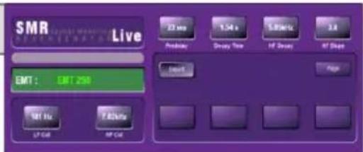
Stereo Tap Delay –
Clean digital delay with link, filters, tap tempo (global or local) and BPM or ms display options.
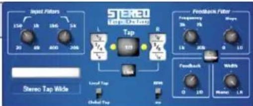
ADT Doubler –
Automatic double tracking unit with double and quad modes, separation, thickness and autopan control.
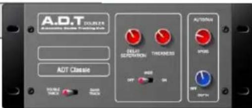
Chorus –
Versatile chorus unit with 3 stereo field options, rate, depth and LFO control, plus autopan option.
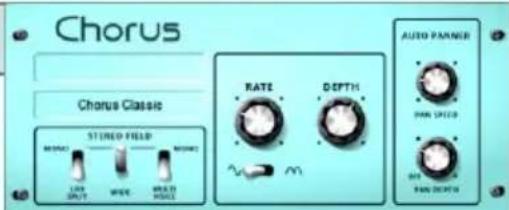
Symphonic Chorus –
A faithful emulation of the 80's classic chorus effect with 2 very simple controls.
Flanger -
3 classic flanger effects in one unit: 'Ambient', 'Vintage' and 'Wild' with multiple LFO and stereo options.
MOO 12 Stage Phaser –
Accurate emulation of a 12 stage phaser, with rich, textured phasing and plenty of control.
Gated Verb –
Emulation of the 80's classic gated reverb, with in-depth control and 2 extra variants: 'Panned' and 'Powerbox'.
MultiBD Compressor 4 –
Fully featured 4 band compressor for dynamic control on input or mix channels.
MultiBD Compressor 3 –
Fully featured 3 band compressor for dynamic control on input or mix channels.
DynEQ4 –
4 band dynamic equaliser, able to carve and shape any sound source.
De-Esser -
Classic De-Essing with auto-threshold for natural sibilance reduction.
Bucket Brigade –
Stereo analogue delay model with vintage bucket brigade sound.
Echo -
Faithful reproduction of the classic tape echo unit.
Hypabass –
Very low distortion sub-harmonic synthesizer to generate low end from sources with weaker bass content.
Information on how to activate these can be found in the Add-ons section.
11. Saving and Recalling Shows/Scenes/Libraries
All mix settings in SQ can be stored and recalled in either ‘Scenes’ or ‘Show’ files. Scenes are intended for recall during use, whilst a Show file contains everything for an event or particular set up. Show files can also be used to make a backup of a configuration or transfer it to another unit.
- A ‘Scene’ is a snapshot of all mix settings.
- There are 300 scene slots available per 'Show'.
- In addition to all of the scenes, a 'Show' includes all SQ settings (such as Chromatic Channel Metering and Integrated Surface Illumination settings).
- The SQ can have one ‘Show’ on it at any one time. Multiple ‘Show’ files can be stored or recalled using SQ-Drive and SQ-MixPad.
- Up to 100 Shows can be stored on each external storage device.
| Stored in each Scene | Stored in each Show |
| Input and output routing | 300 Scenes |
| Input/Mix Stereo settings | Cue List |
| Preamp settings | Scene Manager list mode |
| Channel processing | All Libraries |
| Channel assignments and send levels | Bus Config |
| Panning and balance | Audio Clock source |
| Channel mutes | AES/USB sample rate |
| Mute Groups and DCA assignments and levels | Control Network Bridge state |
| Fader/Channel strip assignments | PAFL and Listen settings |
| Channel names and colours | Talkback settings |
| Ganging | Signal Generator settings |
| Scene filter settings | Master Fader Mode |
| FX units and parameters | Global scene filter settings |
| SoftKey/SoftRotary assignments | Channel safes |
| Footswitch settings | Meter Source Points |
| Chromatic Channel Metering | |
| Surface preferences | |
| MIDI channel |
| Stored in the SQ |
| Network settings |
| Unit name |
| Fader Calibration |
| User Permissions |
11.1 Scene Manager
The Scene Manager allows the current state of the mixer to be stored as a Scene, Scenes can also be recalled, overwritten, deleted or have per-scene recall filters and crossfades applied.
Scene Manager Mode -
Touch the ‘All Scenes’ / ‘Cue List’ button above the scene list to choose the Scene Manager ‘mode’. ‘All Scenes’ works directly with all 300 scene slots. The ‘Cue List’ is like a playlist of cues, each with an associated scene, to allow for easy inserting, reordering, repetition and renumbering.
The Scene Manager mode is global and affects external recall of Scenes via the SQ-MixPad app.
All Scenes Mode -
All 300 scene slots are listed and numbered, touch and drag up and down or touch to select then use the touchscreen rotary to scroll through all slots.
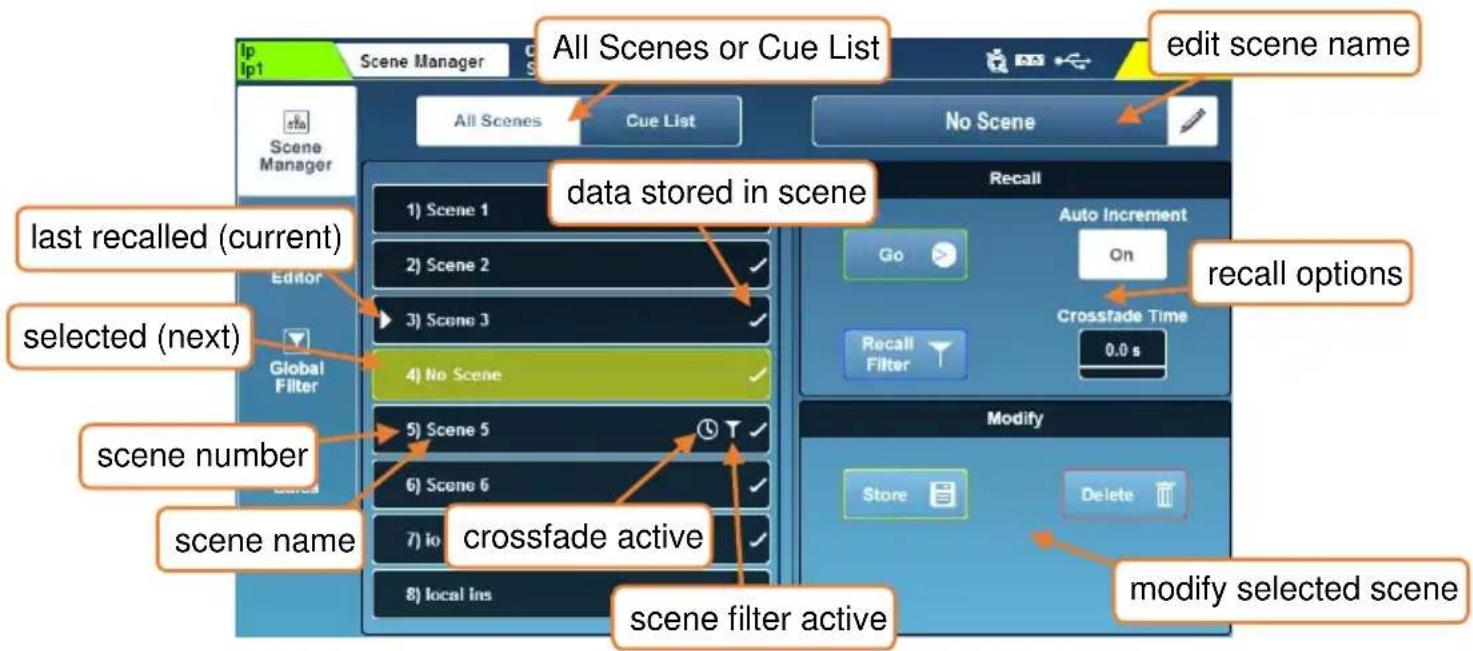
To store the current state of the SQ to a new slot:
- Touch any empty slot.
- Touch the 'Store' button to save with the name 'Scene [slot number]'. OR
- Touch in the empty scene name field to be prompted to name the scene at the same time as storing it.
To recall a scene and replace the current state with the stored state:
- Touch a scene to highlight it then touch the 'Go' button.
To rename a scene:
- Touch the scene, then touch in the edit scene name field at the top of the screen.
To overwrite a scene with the current state of the SQ:
- Touch the scene to overwrite, then touch the 'Store' button.
To delete a scene:
- Touch the scene you wish to delete then touch the 'Delete' button.
You can choose whether or not to confirm scene operations (and avoid accidental overwriting) by using the ‘Confirm Scene Operations’ button found in Surface Preferences.
To quickly copy, paste or delete scenes in All Scenes:
- Hold the 'Copy' key and touch the scene you wish to copy.
- Hold the ‘Paste’ key and touch the scene slot in which you’d like to paste it.
- Hold the 'Reset' key and touch a scene to delete it.
Cue List Mode –
Each Cue in the list has an associated scene from one of the (up to 300) scenes in the current show. Cue numbers are displayed instead of the scene slot number.
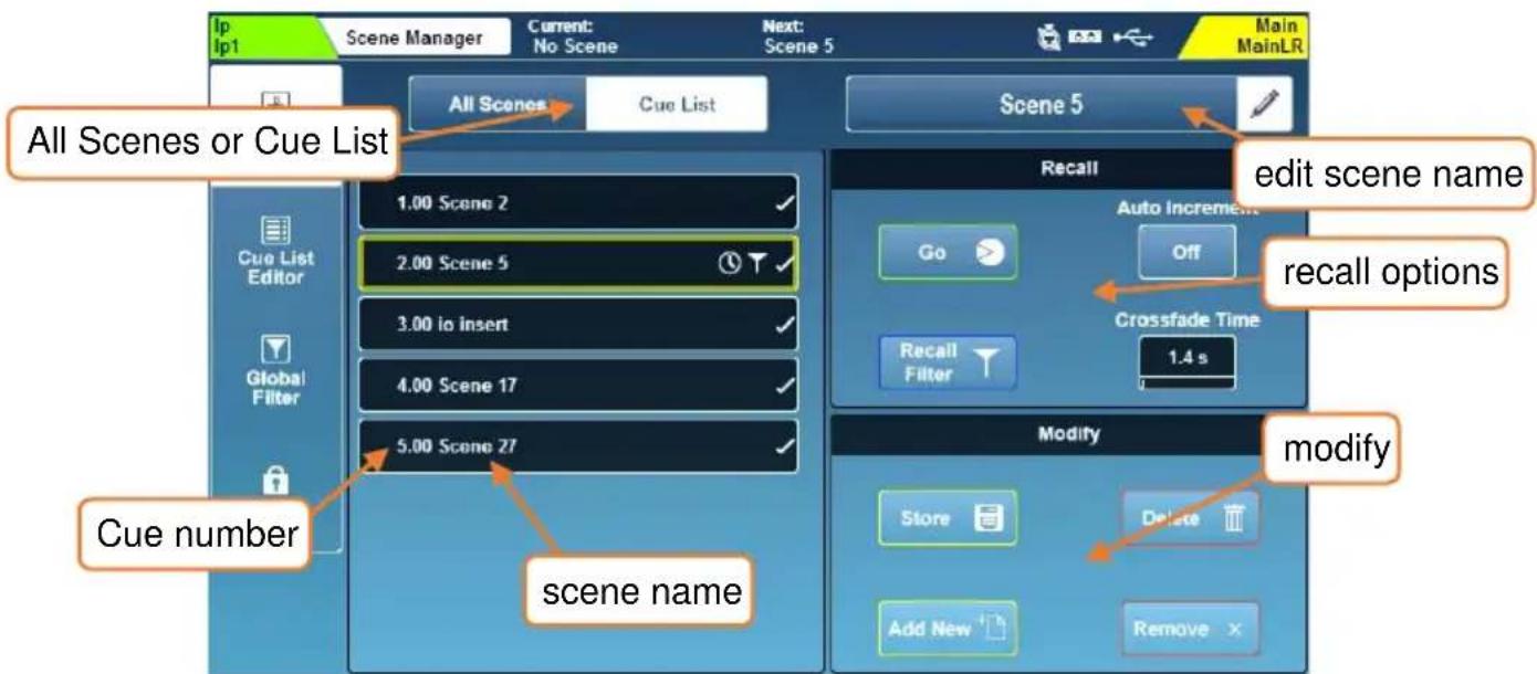
To store the current state of the SQ into the next empty scene slot and add/insert a new cue for that scene after the currently selected cue:
- Touch the 'Add New' button to save with the name 'Scene [slot number]'.
To recall a cue/scene and replace the current state with the stored state:
- Touch a cue/scene to highlight it then touch the 'Go' button.
To rename a scene (note that this renames the scene, not the cue):
- Touch the cue/scene, then touch in the edit scene name field at the top of the screen.
To remove a cue from the Cue List without deleting the associated scene:
- Touch the 'Remove' button.
To overwrite a scene with the current state of the SQ:
- Touch the cue/scene to overwrite, then touch the 'Store' button.
To delete a scene completely (from the Cue List and the SQ):
- Touch the scene you wish to delete then touch the 'Delete' button.
You can choose whether or not to confirm scene operations (and avoid accidental overwriting) by using the ‘Confirm Scene Operations’ button found in Surface Preferences.
Scene Crossfades –
A Crossfade Time can be applied to each scene individually and is stored within that scene.
This smoothly transitions send levels and panning/balance between their previous state and their state in the scene (with the crossfade applied) which is being recalled.
- Select the scene to apply the crossfade to, then select the 'Crossfade Time' value and use the touchscreen rotary to adjust.
Crossfade Time = 0 to 20 seconds
Note that the crossfade applies to audio processing only. Actual fader positions and on-screen values will immediately display where they will be at the end of the crossfade time at the point of recall.
Auto Increment –
With Auto Increment turned on, recalling a scene using the ‘Go’ button on the Scene Manager screen will automatically select the next used scene slot in the All Scenes list or the next scene in the Cue List. Meaning the ‘Go’ button can be pressed repeatedly to move through the scenes sequentially.
The Auto Increment setting on this screen does not affect the ‘Scene Recall Go’ SoftKey option, which has a separate Auto Increment option available.
Scene Filters –
When storing a scene, all mix settings are saved. However, it is possible to filter what is recalled using a combination of scene recall filters and global filters.
See Global Filters for information on what each filter allows or blocks.
To choose which filters are allowed or blocked per scene:
- Touch a scene or cue to highlight it then touch the 'Recall Filter' button.
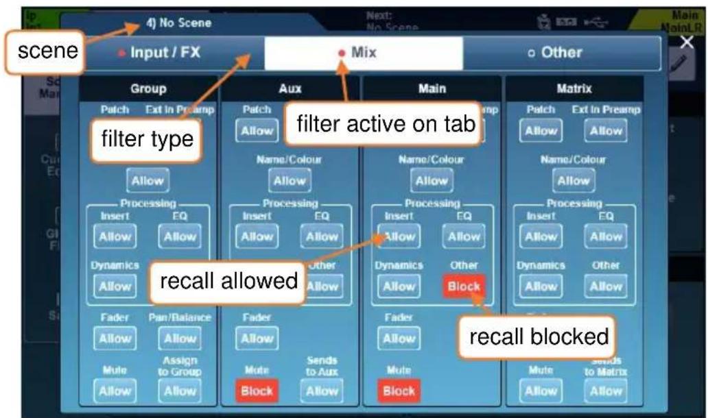
flowchart
graph TD
    A["scene"] --> B["Input / FX"]
    B --> C["Mix"]
    C --> D["Other"]
    D --> E["Group"]
    E --> F["filter type"]
    F --> G["Aux"]
    G --> H["filter active on tab"]
    H --> I["Main"]
    I --> J["Matrix"]
    J --> K["Recall allowed"]
    K --> L["Fader"]
    L --> M["Mute"]
    M --> N["Allow"]
    N --> O["Block"]
    O --> P["Sends to Aux"]
    P --> Q["Allow"]
    Q --> R["Allow"]
    R --> S["Allow"]
    S --> T["Allow"]
    T --> U["Allow"]
    U --> V["Allow"]
    V --> W["Allow"]
    W --> X["Allow"]
    X --> Y["Allow"]
    Y --> Z["Allow"]
    Z --> AA["Allow"]
    AA --> AB["Allow"]
    AB --> AC["Allow"]
    AC --> AD["Allow"]
    AD --> AE["Allow"]
    AE --> AF["Allow"]
    AF --> AG["Allow"]
    AG --> AH["Allow"]
    AH --> AI["Allow"]
    AI --> AJ["Allow"]
    AJ --> AK["Allow"]
    AK --> AL["Allow"]
    AL --> AM["Allow"]
    AM --> AN["Allow"]
    AN --> AO["Allow"]
    AO --> AP["Allow"]
    AP --> AQ["Allow"]
    AQ --> AR["Allow"]
    AR --> AS["Allow"]
    AS --> AT["Allow"]
    AT --> AU["Allow"]
    AU --> AV["Allow"]
- In the pop-up, there are three tabs 'Input/FX', 'Mix' and 'Other' containing all available filters.
- Touch any filter button to switch between 'Allow' and 'Block'.
- Blocked parameters will not be affected when recalling the scene.
The Copy/Paste/Reset keys can also be used with the 'Recall Filter' button when in All Scenes mode.
i Global Recall Filters take precedence over Scene Recall Filters.
Reset Mix Settings –
If wanting to start with default mix settings, it is possible to reset the mix to a default state without deleting any scenes. See Reset Mix Settings for more information.
11.2 Cue List Editor
The Cue List Editor allows cues to be added, inserted and removed from the Cue List in the same way as is possible in Cue List mode in the Scene Manager screen. Additionally, it's possible to clear the Cue List completely as well as reorder and renumber it.
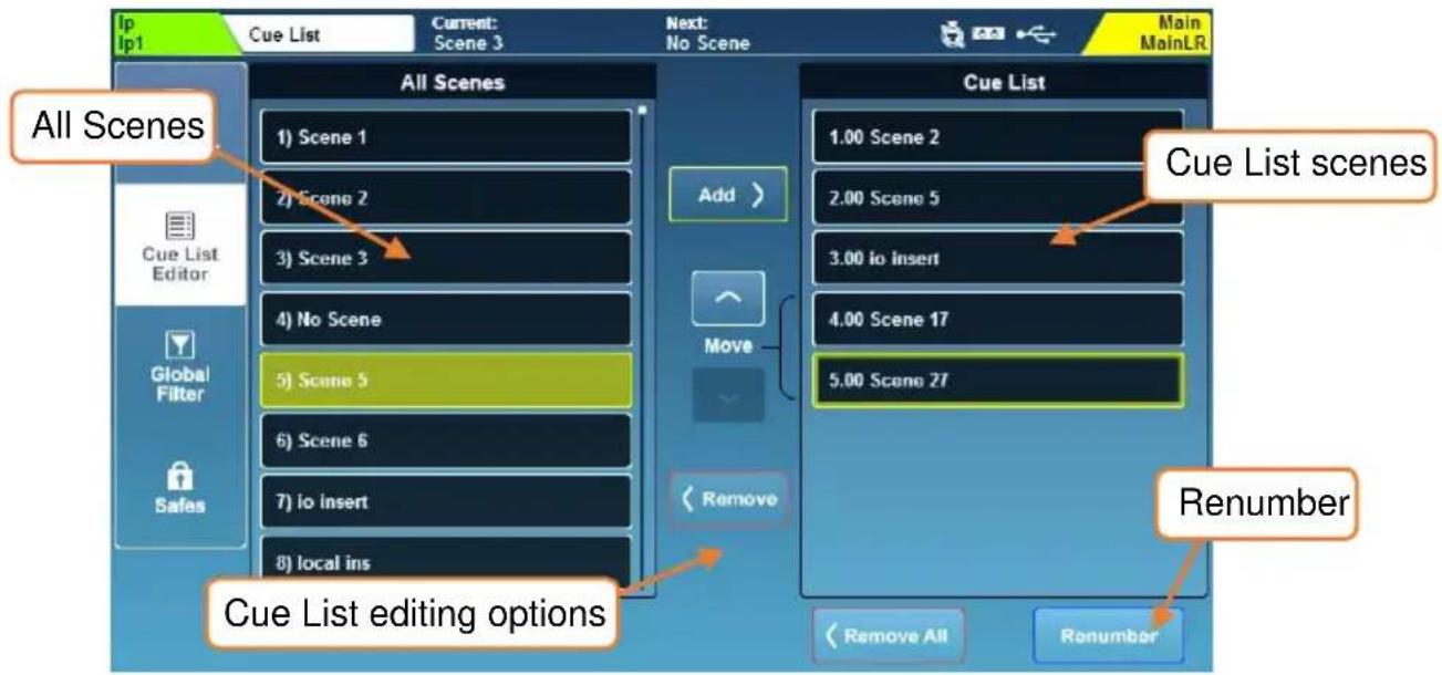
To add/insert a new cue for a scene into the Cue List:
- Touch a stored scene in the All Scenes list on the left.
- Touch a cue in the Cue List on the right.
- Touch 'Add' to add a cue for the selected scene after the selected cue.
When inserting a new cue, it will be automatically numbered based on its position in the Cue List.
To remove scenes from the Cue List (this will not delete scenes from the SQ, only remove the cue for it from the Cue List):
- Touch the cue to be removed.
- Touch the 'Remove' button to remove it.
OR
- Touch the 'Remove All' button to completely clear the Cue List.
Cue List numbering and renumbering –
The Cue List is numbered to two decimal places, allowing scenes inserted between two existing scenes in the Cue List to be automatically assigned a number between the two without changing the existing numbering.
This is for systems and setups using external triggering via MIDI Show Control to prevent those triggers from needing to be changed if extra scenes are inserted.
It is possible to renumber the Cue List scenes at any time however, by touching the 'Renumber' button to show the Renumbering popup.
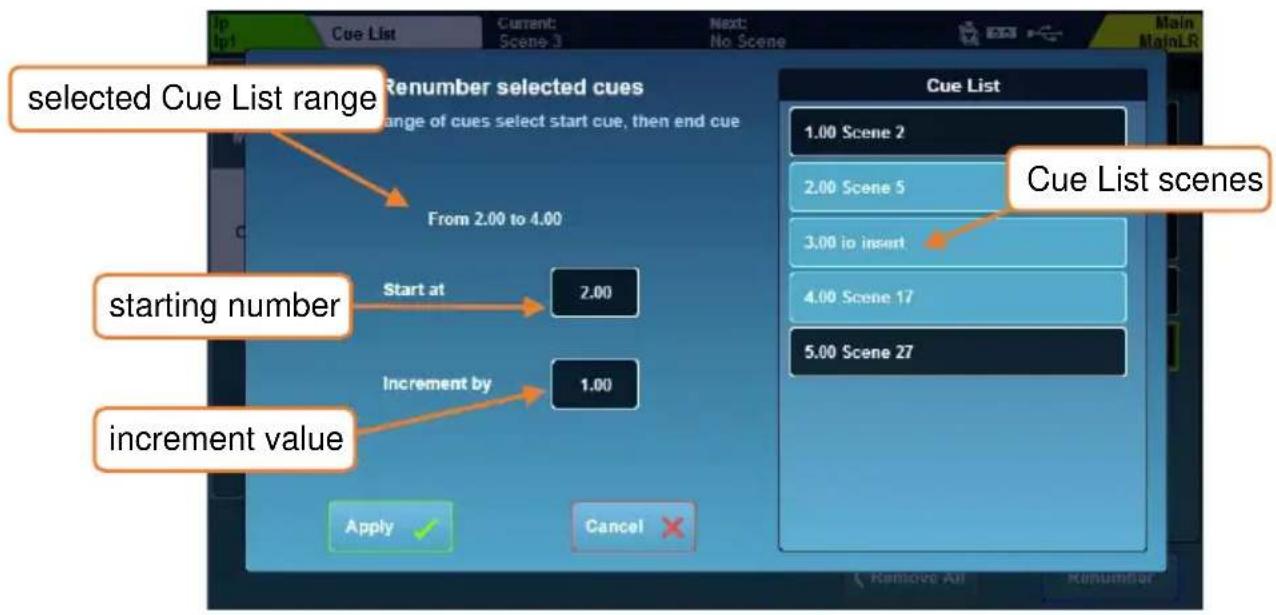
To renumber a range of cues in the Cue List:
- Touch the first cue in the range you wish to renumber.
- Touch the last cue in the range you wish to renumber.
- Touch the 'Start at' value and use the touchscreen rotary to select the number for the first cue in the range.
- Touch the ‘Increment by’ value and use the touchscreen rotary to select how much the number for each consecutive cue will be incremented by.
- Touch the 'Apply' button.
Setting ‘impossible’ values that clash with or overlap existing cues will cause the ‘Apply’ button to be greyed out.
Setting a 'Start at' value higher than the final cue is possible, but will move the range of cues to the end of the Cue List to ensure all cues remain in numerical order.
Setting values which allow the entire range to fit between two existing cues is possible and will move the range to that position to ensure all cues remain in numerical order.
11.3 Global Filters
Global scene filters are always active, and affect which settings are changed when recalling a scene. They also override any active scene filters.
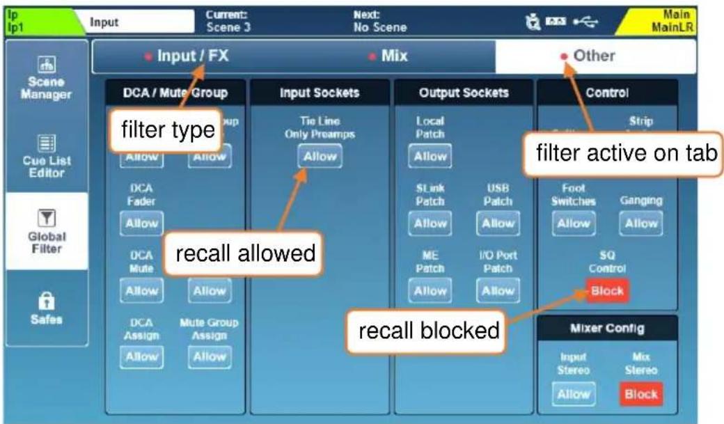
- Touch any filter button to switch between 'Allow' and 'Block'.
- Blocked parameters will not be affected when recalling scenes.
It is common to block 'SoftKeys', 'SoftRotaries', 'Footswitches' and 'SQ-Control', so they continue to function in the same way whenever scenes are recalled.
Changes to Talkback and PAFL Ext In patching and preamp parameters are always blocked as these are show level parameters.
All output socket filters also affect socket settings e.g. AES sample rate setting.
Input/FX Filters –
| Inputs | |
| Filter | Includes |
| Patch | Source and Direct Out patching of input channels |
| Preamp | Preamp settings of input channels (excludes DEEP preamp models) |
| Name/Colour | All input channel names and colours |
| Processing/Insert | All Input channel insert patching and settings |
| Processing/EQ | All Input channel HPF and PEQ settings |
| Processing/Dynamics | All Input channel Gate and Compressor settings |
| Processing/Other | All Input channel Trim, DEEP preamp, Stereo Image and channel Delay settings |
| Fader | All input channel fader positions and assignments to the Main LR mix |
| Pan/Balance | All input channel panning and balance to Main LR mix |
| Mute | All input channel mutes |
| AMM | All AMM assignments and settings |
| FX | |
| Filter | Includes |
| Patch | All FX input patching (Mix->Return or Insert) and output patching |
| Name/Colour | All FX Send and Return channel names and colours |
| Parameters | All FX parameters and wet/dry mix settings |
| Fader | All FX Send and Return channel fader positions |
| Return Balance | All FX Return channel balance positions |
| Mute | All FX Send and Return channel mutes |
| Sends to FX | All send levels and assignments to FX busses |
Mix Filters –
| Group | |
| Filter | Includes |
| Patch | Mix Ext In source plus output patching of Group channels |
| Ext In Preamp | Preamp settings of Group Mix Ext In |
| Name/Colour | All Group channel names and colours |
| Processing/Insert | All Group channel insert patching and settings |
| Processing/EQ | All Group channel GEQ and PEQ settings |
| Processing/Dynamics | All Group channel Compressor settings |
| Processing/Other | All Group channel Delay settings |
| Fader | Master fader positions and output balance of Group channels |
| Pan/Balance | Master pan and balance positions for all Group channels |
| Mute | Master mute for all Group channels |
| Assigns to Group | All channel assignments to all groups |
| Aux | |
| Filter | Includes |
| Patch | Mix Ext In source plus output patching of Aux channels |
| Ext In Preamp | Preamp settings of Aux Mix Ext In |
| Name/Colour | All Aux channel names and colours |
| Processing/Insert | All Aux channel insert patching and settings |
| Processing/EQ | All Aux channel GEQ and PEQ settings |
| Processing/Dynamics | All Aux channel Compressor settings |
| Processing/Other | All Aux channel Delay settings |
| Fader | Master fader positions and output balance of Aux channels |
| Mute | Master mute for all Aux channels |
| Sends to Aux | All send levels to Aux channels |
| Main | |
| Filter | Includes |
| Patch | Mix Ext In source plus output patching of the Main LR channel |
| Ext In Preamp | Preamp settings of Main LR Mix Ext In |
| Name/Colour | Main LR channel name and colour |
| Processing/Insert | Main LR channel insert patching and settings |
| Processing/EQ | Main LR channel GEQ and PEQ settings |
| Processing/Dynamics | Main LR channel Compressor settings |
| Processing/Other | Main LR channel Delay settings |
| Fader | Master fader positions and output balance of the Main LR channel |
| Mute | Master mute for all Main LR channel |
| Matrix | |
| Filter | Includes |
| Patch | Mix Ext In source plus output patching of Matrix channels |
| Ext In Preamp | Preamp settings of Matrix Mix Ext In |
| Name/Colour | All Matrix channel names and colours |
| Processing/Insert | All Matrix channel insert patching and settings |
| Processing/EQ | All Matrix channel GEQ and PEQ settings |
| Processing/Dynamics | All Matrix channel Compressor settings |
| Processing/Other | All Matrix channel Delay settings |
| Fader | Master fader positions and output balance of Matrix channels |
| Mute | Master mute for all Matrix channels |
| Sends to Matrix | All send levels to Matrix channels |
Other Filters –
| DCA/Mute Group | |
| Filter | Includes |
| DCA Name/Colour | All DCA names and colours |
| Mute Group Name | All Mute Groups names |
| DCA Fader | All DCA fader values |
| DCA Mute | All DCA mutes |
| Mute Group Mute | All Mute Group mutes |
| DCA Assign | All DCA member assignments |
| Mute Group Assign | All Mute Group assignments |
| Input Sockets | |
| Filter | Includes |
| Tie Line Only Preamps | Preamp parameters for connected sockets not assigned to a channel |
| Output Sockets | |
| Filter | Includes |
| Local Patch | All patching to local output sockets (XLR, TRS and AES) |
| SLink Patch | All patching to the SLink port |
| USB Patch | All patching to USB (SQ-Drive and USB-B) |
| ME Patch | All patching to the ME system (SLink or I/O Port) |
| I/O Port Patch | All patching to the I/O Port |
| Control | |
| Filter | Includes |
| SoftKeys | All SoftKey assignments |
| Strip Assign | Channel strip layout |
| Soft Rotaries | All Soft Rotary assignments |
| Footswitches | Footswitch assignments |
| Ganging | All ganging assignments and linked parameters |
| SQ-Control | SQ-Control layout |
| Mixer Config | |
| Filter | Includes |
| Input Stereo | Mono/stereo state of odd/even Input channel pairs |
| Mix Stereo | Mono/stereo state of Group, Aux and Matrix channels |
11.4 Safes
'Safes' block any changes to a channel when recalling a scene.
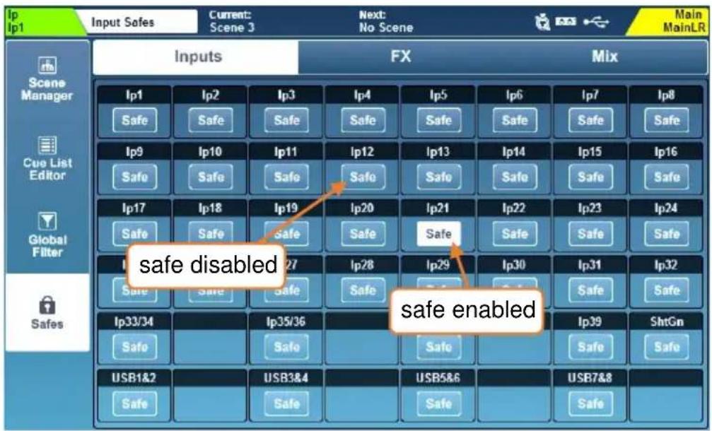
- Touch 'Input', 'FX' or 'Mix' tabs to view all channel safes.
- Touch a 'Safe' button to safe the channel (the button will turn white).
11.5 Libraries
Factory Libraries and User Libraries are available for many features and processing in SQ and can be accessed by using the dedicated Library key when in certain screens.
Throughout this document, where a library is available for use, it is noted with an image of the library key next to the screen image.
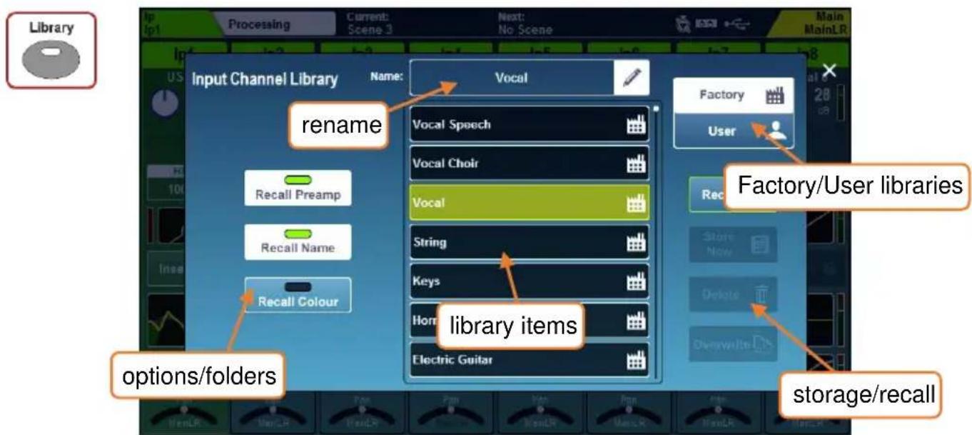
Factory libraries provide presets and are also used to recall different FX units or DEEP plug-ins. They are fixed in firmware and cannot be edited or overwritten.
To recall from the library:
- Go to the screen you wish to recall parameters for.
- Press the 'Library' key.
- Select the Factory or User library item you wish to recall.
- Touch the 'Recall' button.
To store or overwrite a library item:
- Go to the screen you wish to store parameters for with the settings you wish to store visible.
- Press the 'Library' key.
- Select the User library in the top right of the screen.
- Touch the 'Store New' button to store a new library item.
OR
- Select a library item and touch the 'Overwrite' button.
To delete a library item:
- Select the User library in the top right of the screen.
- Select the library item you wish to delete.
- Touch the 'Delete' button then confirm to delete the item.
Libraries are available in the following screens.
| Library | Screen | Includes |
| Input Channel | Processing overview (input selected) | All input channel processing - Options for Preamp, Name and Colour recall |
| Mix Channel | Processing overview (mix selected) | All mix channel processing - Options for Ext In Preamp, Name and Colour recall |
| Preamp Model | Processing > Preamp (input selected) | DEEP preamp model and parameters |
| Gate | Processing > Gate | Gate parameters |
| GEQ | Processing > GEQ | DEEP GEQ models and parameters |
| PEQ | Processing > PEQ | PEQ parameters - Option for HPF |
| Compressor | Processing > Compressor | DEEP compressor models and parameters |
| FX | FX (rack selected) | FX units and parameters, including Wet/Dry mix |
| User Permissions | Setup > Users (User 1- 10 selected) | User permission settings |
| Input Channel Patch | I/O > Inputs > Input Channel | All patching for Input Channels |
11.6 Data Transfer (USB/MixPad)
All data transfer options are located in the 'Utility' screen, in the 'Data' tab. These enable shows and individual scenes and libraries to be stored and recalled, and are used to back-up data or transfer it to another SQ.
USB Shows –
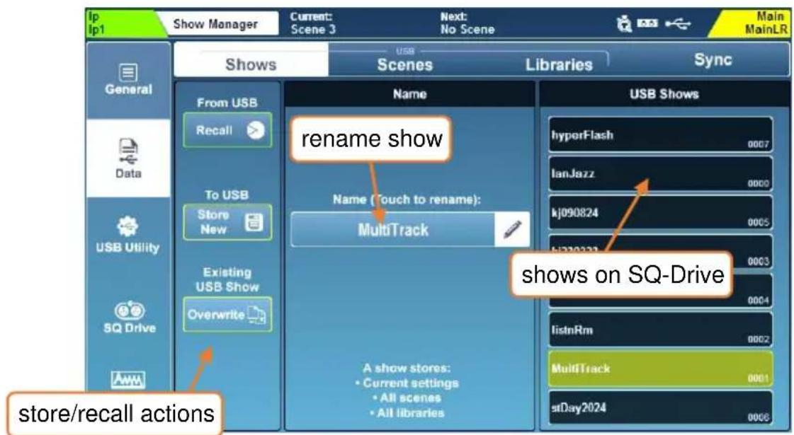
To store a show to a USB device:
- Touch the 'Store New' button - you will be prompted to name the show.
To recall a show:
- Touch a show to highlight it (use the touchscreen rotary to change selection or scroll through all shows) then touch the 'Recall' button.
To rename a scene:
- Touch a show, then touch in the 'Name' field in the centre of the screen.
To overwrite a scene:
- Touch the scene to overwrite, then touch the 'Overwrite' button.
i Storing or recalling shows is not possible when SQ-Drive is being used for recording or playback.
i Storing or recalling shows will interrupt USB-B audio streaming.
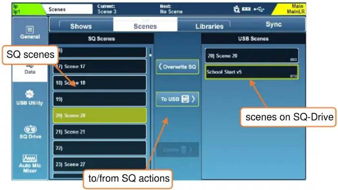
To store an individual scene to a USB device:
- Touch to select the scene you wish to store in the 'SQ Scenes' list on the left.
- Touch the 'To USB' button.
To transfer a scene from USB to the SQ:
- Touch to select the scene to transfer in the 'USB Scenes' list on the right.
- Touch to select an empty slot in the 'SQ Scenes' list on the left.
- Touch the 'To SQ' button to transfer.
To overwrite a scene:
- Touch to select the scene to transfer in the 'USB Scenes' list on the right.
- Touch to select the scene to overwrite in the 'SQ Scenes' list on the left.
- Touch the 'Overwrite SQ' button to transfer and overwrite the SQ scene.
To delete a scene from USB:
- Touch to select the scene to delete in the 'USB Scenes' list on the right.
- Touch the 'Delete' button and confirm the action in the pop-up.
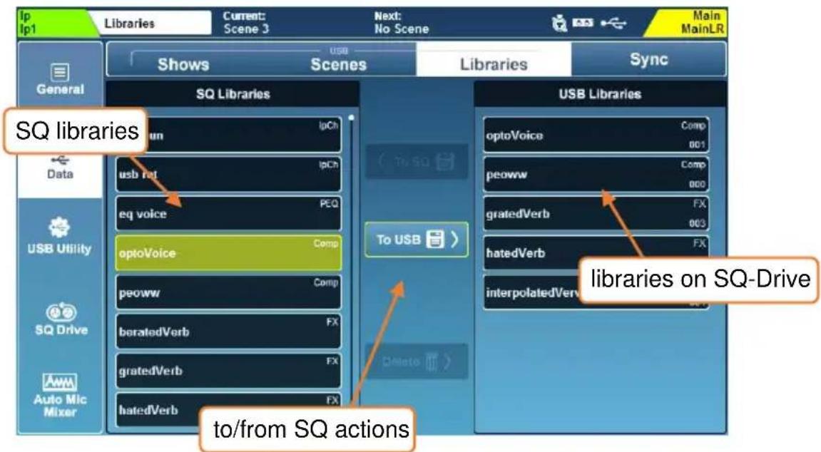
To store an individual library item to a USB device:
- Touch to select the library item you wish to store in the 'SQ Libraries' list on the left.
All user libraries in the current show are displayed.
- Touch the 'To USB' button.
To transfer a library item from USB to the SQ:
- Touch to select the library to transfer in the 'USB Libraries' list on the right.
- Touch the 'To SQ' button to transfer.
To overwrite a library item:
- Touch to select the library item to transfer in the 'USB Libraries' list on the right.
- Touch to select the library item to overwrite in the 'SQ Libraries' list on the left.
- Touch the 'Overwrite SQ' button to transfer and overwrite the SQ library item.
To delete a library item from USB:
- Touch to select the library item to delete in the 'USB Libraries' list on the right.
Touch the 'Delete' button and confirm the action in the pop-up.
Sync -
To push or pull data using the SQ-MixPad app, the SQ console must be in sync mode. This avoids accidental overwriting of data on both the SQ console and SQ-MixPad.
To enter sync mode, go to the 'Utility' screen, then touch 'Data' followed by 'Sync'.
Touch the 'Sync Mode' button then confirm you understand the implications of sync mode in the pop-up to proceed.
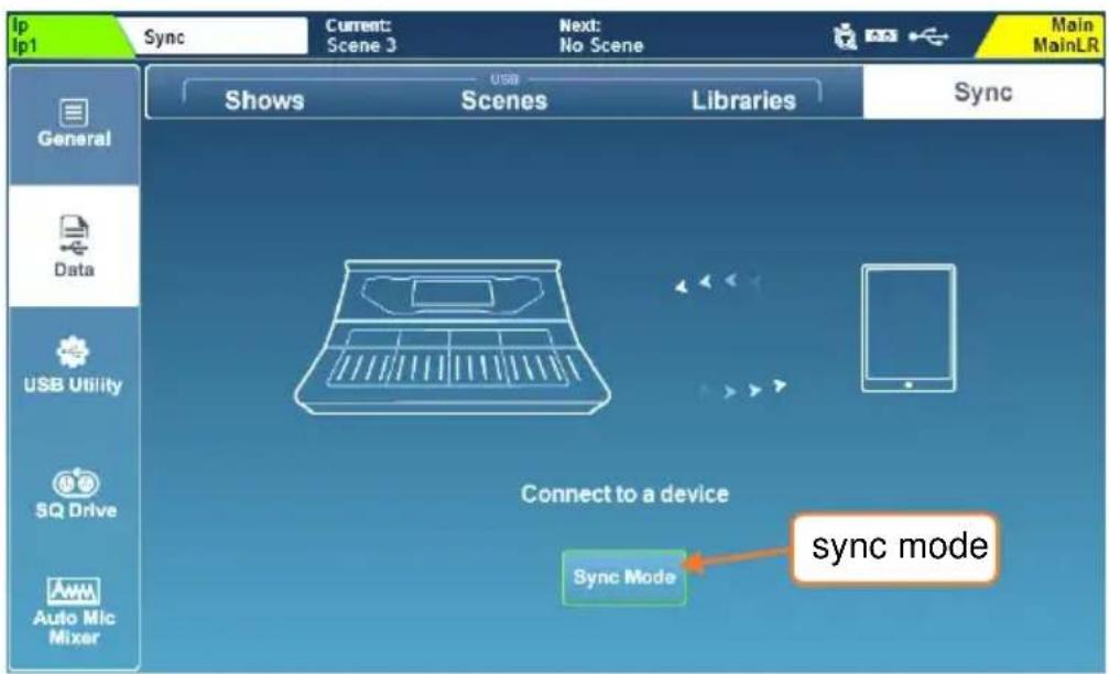
Once in sync mode, pushing and pulling of data is controlled by SQ-MixPad.
User permissions for the current user of both the console and SQ-MixPad must allow 'Sync Push' and/or 'Sync Pull' to transfer a show.
Refer to SQ-MixPad help for more information on data transfer to and from MixPad.
Starting sync mode will disconnect all devices aside from the one being connected to as all network bandwidth is required without interruption.
12. Setup
12.1 Strip Assign
All fader strips on the SQ are freely assignable.
Press the 'Setup' screen key, touch the 'Surface' tab then touch the 'Strip Assign' tab.
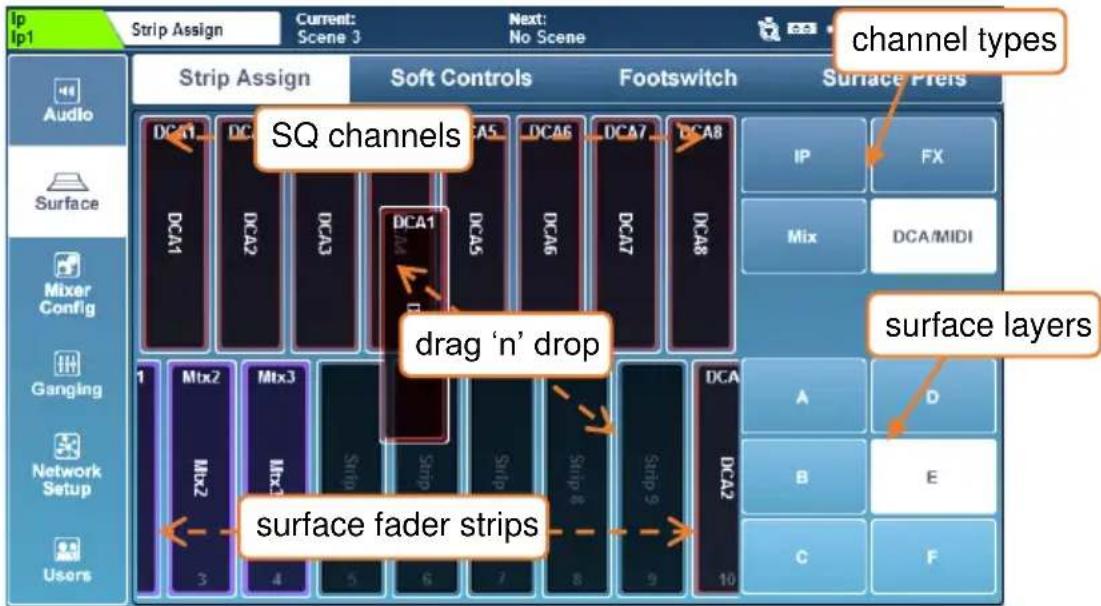
- SQ channels are displayed in the top half of the screen. Select channel types by touching buttons at the right, and touch and drag left or right to view all available channels.
- Fader strips are displayed in the bottom half of the screen. Select layers by touching the buttons to the right or switching layers on the surface, then touch and drag left or right to view all available fader strip slots.
- To assign channels to fader strips, touch and drag them from the top row to a fader strip in the bottom row.
- To remove assignments, touch and drag them out of the fader strip at the bottom towards the top of the screen.
FX return channels can be assigned to fader strips but will not be visible unless they are routed from the output of the FX engine (i.e. set as 'Mix -> Return' on the back panel).
The ‘Listen’ bus is not a channel type, but the Master fader or a Soft Rotary can be used to control Listen Level. See the Mixer Role section for more information.
12.2 Input Mono/Stereo Configuration
To use input channels as stereo channels throughout the mixer, they must first be switched into stereo mode.
In the 'Setup' screen, touch the 'Mixer Config' tab, then touch 'Input Stereo'
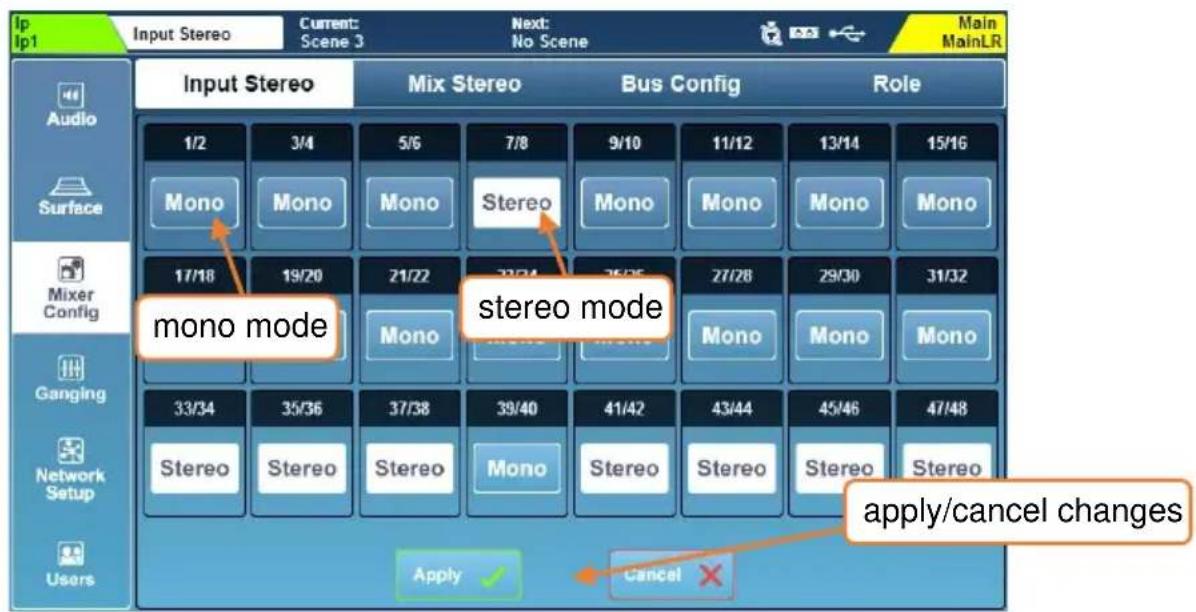
- Odd/even pairs of input channels can be switched between mono and stereo mode by touching the 'Mono/Stereo' button.
- Touch the 'Apply' button to apply any changes.
- Touch the 'Cancel' button to undo changes and display the current state.
By default, changes to Input and Mix mono/stereo state on scene recall are blocked by Global Filters.
12.3 Mix Mono/Stereo Configuration
Mixes can be used as mono or stereo channels throughout the mixer. When set to stereo, signals sent from mono input channels can be panned and stereo signals are passed through in stereo with balance control. When set to mono, stereo signals are summed.
In the 'Setup' screen, touch the 'Mixer Config' tab, then touch 'Mix Stereo'.
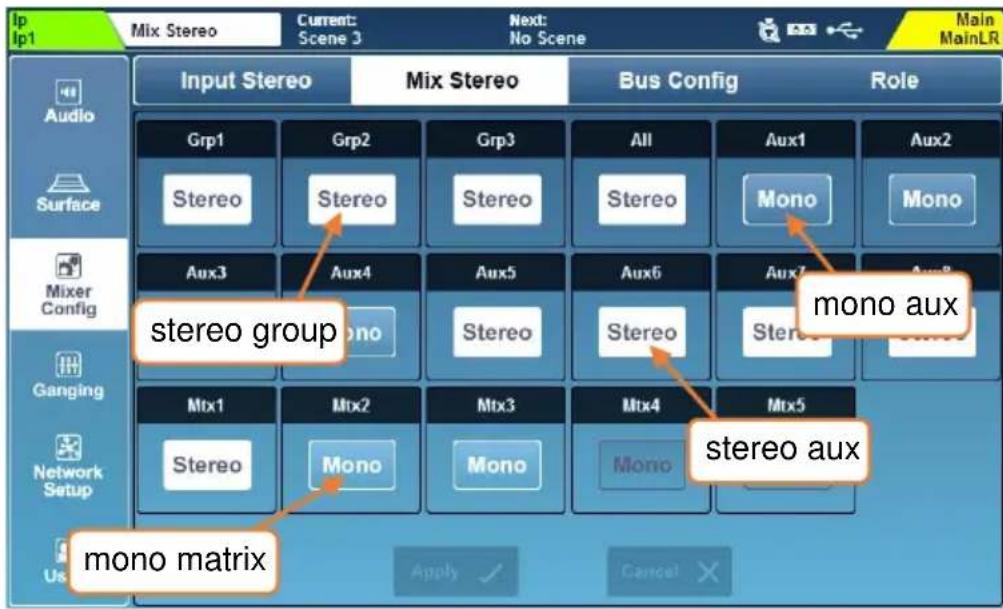
- Any mix can be switched between mono and stereo mode by touching the 'Mono/Stereo' button.
- Touch the 'Apply' button to apply any changes.
- Touch the 'Cancel' button to undo changes and display the current state.
By default, changes to Input and Mix mono/stereo state on scene recall are blocked by Global Filters.
Extra Matrices –
Switching each of stereo Matrix 1, 2 or 3 to mono will enable an extra mono matrix, to provide up to 6 mono matrices in total.
Switching any of them back to stereo will always remove the highest numbered mono matrix first.
Processing, Routing and other settings for mono Matrix channels 4-6 is always stored when storing a scene, even if the matrix itself is unavailable due to being in use by a stereo matrix. In this way, if the matrix is made available again, no settings will have been lost.
12.4 Mix Aux/Group Bus Configuration
The 12 mixes can be switched between group and auxiliary modes under the 'Bus Config' tab.
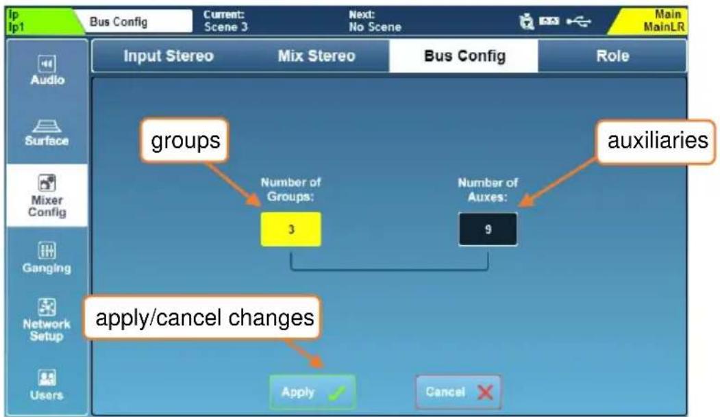
flowchart
graph TD
    A["groups"] --> B["Number of Groups: 3"]
    C["auxiliaries"] --> D["Number of Auxes: 9"]
    E["apply/cancel changes"] --> F["Apply ✓"]
    G["Cancel ✗"] --> H["End"]
- Touch either the 'Number or Groups' value or the 'Number of Auxes' value, then adjust using the touchscreen rotary.
- Increasing the number of groups will decrease the number of auxiliaries and vice versa.
- Touch the 'Apply' button to apply any changes.
Auxiliaries will always be assigned sequentially to the first mix keys, with groups assigned afterwards. For example, if you configure the buses as 5 groups and 7 auxes, auxes 1 to 7 will be on mix keys 1 to 7 and groups 1 to 5 will be on mix keys 8 to 12.
Mix keys assigned to auxes illuminate blue when active, and mix keys assigned to groups illuminate magenta.
12.5 SoftKeys/SoftRotaries
SoftKeys and SoftRotaries allow you to customise surface controls of the SQ.
Press the 'Setup' screen key, then touch the 'Surface' tab followed by the 'Soft Controls' tab to view and adjust SoftKey and SoftRotary assignments.
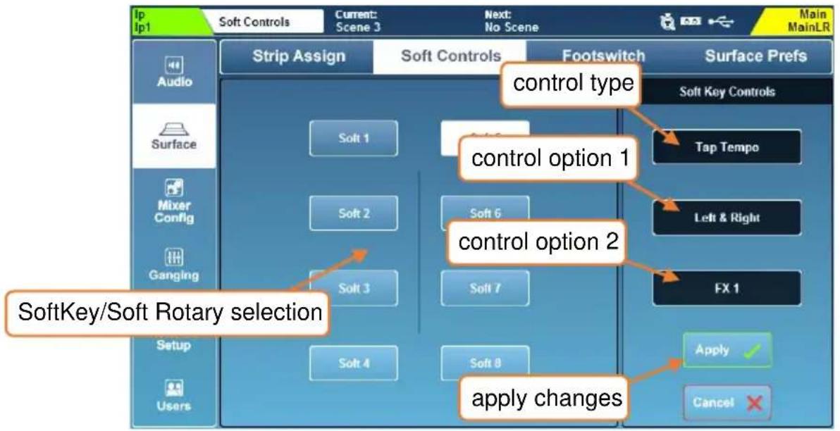
To change the function of a SoftKey or SoftRotary:
1) Touch either 'Soft Keys' or 'Soft Rotaries' (SQ-6, SQ-7, SQ-Rack).
2) Touch a numbered SoftKey or SoftRotary button, these match the labelling on the surface of the SQ and turn white when selected.
3) Touch the control type value and select a type.
4) Touch the control option 1 value (where available) and select an option.
5) Touch the control option 2 value (where available) and select an option.
6) For Soft Rotaries on SQ-6, SQ-7 and SQ-Rack there is a third control option to select the function of the associated key.
7) Touch the 'Apply' or 'Cancel' button, to apply or disregard any changes.
SoftKeys illuminate with different colours depending on function. When assigned to a Tap Tempo, they flash to display the current tempo.
Each SoftRotary has an LCD display, an assignable key and is illuminated when active, with the colour of the rotary and key relating to the assigned function.
- The SoftRotary LCD display momentarily displays parameter value when adjusted.
- Press the 'View' key multiple times to display Soft Rotary function and value.
| Possible SoftKey assignments | |||
| Control Type | Control Option 1 | Control Option 2 | Colour |
| Unassigned | N/A | N/A | N/A |
| AMM Channel On/Off | N/A | All input channels | Green |
| AMM In/Out | N/A | AMM 1, AMM 2 | Green |
| Channel Mute | N/A | All audio channels | Red |
| Channel PAFL | N/A | All audio channels | Yellow |
| DAW Control | N/A | Bank Up, Bank Down | N/A |
| DCA Mute | N/A | DCA's 1 to 8 | Red |
| DCA PAFL | N/A | DCA's 1 to 8 | Yellow |
| DCA Spill | N/A | Spill On Sel, DCA's 1 to 8 | Magenta/Green |
| MIDI note On/Off | MIDI Channel | Note | Red |
| MIDI Program change | MIDI Channel | Program 0 - 127 | Red |
| Mix Select | N/A | All mixes | Blue/Magenta |
| MMC | N/A | Rewind, Play, Pause, Stop, FFwd, Record | Red |
| Mute Group | N/A | Mute Groups 1 to 8 | Red |
| PAFL Clear | N/A | N/A | Red |
| Recall Scene | N/A | All saved scenes | Red |
| Scene Next | N/A | N/A | Red |
| Scene Previous | N/A | N/A | Red |
| Scene Recall Go | None, Auto Increment | N/A | Red |
| Scene Store Current | N/A | N/A | Red |
| Select | Layer A-F | Channel strip number | Green |
| SQ Drive Multitrack | N/A | Previous, Stop, Start/Pause, Arm recording, Next, Arm/Rec/Stop | Blue/Red/Green |
| SQ Drive Stereo Play | N/A | Previous, Stop, Start/Pause, Next | Blue/Red/Green |
| SQ Drive Stereo Record | N/A | Stop, Start/Pause, Arm recording, Arm/Rec/Stop | Blue/Red/Green |
| Talk | N/A | N/A | Green |
| Tap Tempo | Left, Right, Left & Right | FX engines 1 to 8 | Yellow |
| Global Tap Tempo | N/A | N/A | Yellow |
| Possible SoftRotary assignments | |||
| Control Type | Control Option 1 | Control Option 2 | Key |
| Unassigned | N/A | N/A | N/A |
| AMM Priority | Current Selection, all input channels | N/A | Unassigned, On |
| Compressor | Threshold, Ratio, Gain, Attack, Release | Current Selection, all input and mix channels | Unassigned, In |
| DCA Level Fader | DCA's 1 to 8 | N/A | Unassigned, Mute, PAFL, Spill |
| FX Parameter | Time*, Amount* | Rack FX Slot (1-8) | Unassigned, Tap Tempo, Mute Send, Mute Return, Insert In |
| Gate | Threshold, Depth, Attack, Hold, Release | Current Selection, all input channels | Unassigned, In |
| HPF Frequency | Current Selection, all input channels | N/A | Unassigned, In |
| Main Level Fader | Current Selection, all main send levels | N/A | Unassigned, Mute, PAFL |
| MIDI absolute | MIDI Channel | CC# | Unassigned, Note |
| MIDI relative | MIDI Channel | CC# | Unassigned, Note |
| MIDI Program Change | MIDI Channel | N/A | Sends MIDI |
| PAFL Listen Level | N/A | N/A | N/A |
| Pan | Current Selection, all input and mix channels | Current Mix, all stereo aux | Unassigned, Centre |
| PEQ Band | LF, LM, HM, HF | Current Selection, all input and mix channels | Gain/Width/Freq |
| Preamp model | Fine Adjustment, Level | Current Selection, all input channels | Unassigned, In |
| Preamp | Gain, Trim | Current Selection, all input and mix channels | Unassigned, Pad, Polarity |
| Send Level Fader | Current Selection, all input and mix channels | Current Mix, Main LR, all aux and FX sends | Unassigned, Assign (to mix) |
| *FX Parameter ‘Time’ and ‘Amount’ functions for different FX units | ||
| FX Unit | Time | Amount |
| SMR Reverb | Decay Time | N/A |
| Gated Verb | N/A | N/A |
| Stereo Tap Delay | Delay Time (L - use ‘Link’ for R) | Feedback Amount |
| ADT | Delay Separation | Thickness |
| Blue Chorus | Rate | Depth |
| Symphonic Chorus | Frequency | Depth |
| Flanger | Speed | Depth |
| Phaser | Rate | Depth |
12.6 Footswitch
Connect a single or dual, momentary or latching footswitch with a TS or TRS 14 " jack plug to the 'Footswitch' socket to allow hands-free control of the SQ.
In the 'Setup' screen, touch the 'Surface' tab then the 'Footswitch' tab to display and adjust the footswitch settings and assignments.
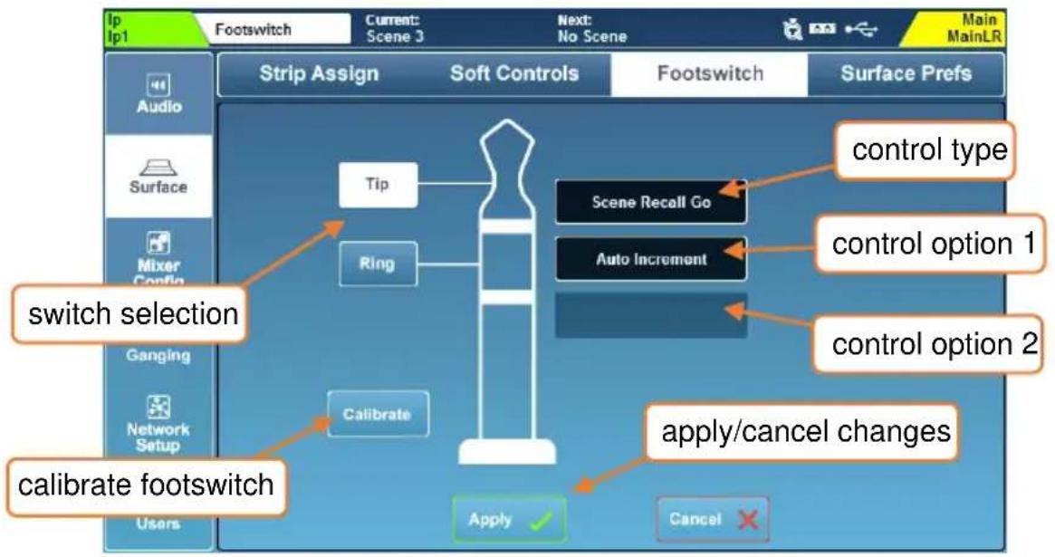
When first connecting a footswitch, touch the 'Calibrate' button to set the type of switch being used. Follow the on-screen instructions.
- Single footswitches usually use only the 'Tip' connection.
- You may need to experiment to find which switch is connected to tip or ring with a dual footswitch.
Options for the type of switch are as follows and must match the footswitch hardware:
Unused = Select for a switch you do not wish to use.
Latching = Press and release to switch on, press again to switch off.
Momentary = Press and hold to switch on, release to switch off.
Soft Latch = Enables a momentary switch to be used as a latching switch.
To assign a function to a footswitch:
1) Touch either 'Tip' or 'Ring' buttons to select a switch.
2) Touch the control type value and select a type.
3) Touch the control option 1 value (where available) and select an option.
4) Touch the control option 2 value (where available) and select an option.
5) Touch the 'Apply' or 'Cancel' button, to apply or disregard any changes.
① Available footswitch assignments closely match those for SoftKeys.
12.7 Surface Preferences
Press the 'Setup' key, then touch the 'Surface' tab followed by the 'Surface Prefs' tab to see the surface preferences.
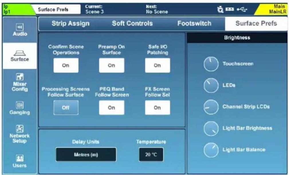
This screen can also be accessed by pressing the 'Brightness' button on the 'Home' page.
- Touch the 'Confirm Scene Operations' button to enable or disable confirmation pop-ups when performing scene overwriting/recalling/deleting operations.
- Touch the ‘Preamp On Surface’ button to choose whether the dedicated surface preamp rotary can adjust preamp gain (when ‘Off’ the rotary controls Trim instead).
- Touch the 'Safe I/O Patching' button to enable or disable safe patching in the I/O screen. When 'Off' the 'Patch' button will not be displayed at all.
- Touch the ‘Processing Screens Follow Surface’ button to enable or disable the option for processing screens to change to the last adjusted parameter.
- Touch the 'PEQ Band Follow Screen' button to choose whether the band selection on the surface follows the on-screen PEQ band selection.
- Touch the 'FX Screen Follow Sel' button to enable or disable FX unit selection in the FX screen following which channels are selected.
The ‘Preamp on surface’ setting is useful when there is a digital split between two consoles and gain adjustments would affect both. Instead, it allows quick adjustment of trim, which is local to the console.
i 'FX Screen Follow Sel' means the FX unit selected in the FX screen will follow selection of FX send and return, as well as any channel where an FX unit has been inserted.
Channel Delay Controls –
'Delay Units' changes the units displayed on all input and mix processing channel delays.
Delay Units = Millisecond (ms)
Meters (m)
Feet (ft)
Samples (S)
As the speed of sound through air depends on the temperature of the air, selecting a measure of distance will allow the 'Temperature' value to be changed. This should be set to match the ambient temperature of the air.
Temperature = -20^ to +40^ -4^ to +104^
If Meters is selected, temperature is shown in Celsius. If Feet is selected, temperature is shown in Fahrenheit.
① Note that these values extend outside the operating temperature range of the SQ.
Brightness –
These settings individually control the brightness of illumination across the SQ.
- Touch a parameter dial and adjust using the touchscreen rotary.
Touchscreen = The touchscreen backlight
LED's = All surface LED's including keys, channel and PAFL metering
Channel Strip LCDs = Channel naming strip LCD backlights
Light Bar Brightness = Brightness of the integrated illumination
Light Bar Balance = Colour of the integrated illumination
12.8 PAFL
The Pre/After Fade Listen settings affect the behaviour of the PAFL bus which is routed to the SQ headphone output and displayed on the 12 segment LED meter as well as being routed to the SQ's RTA.
Press the 'Setup' screen key, then touch the 'Audio' tab, followed by the 'PAFL' tab to display and adjust settings.
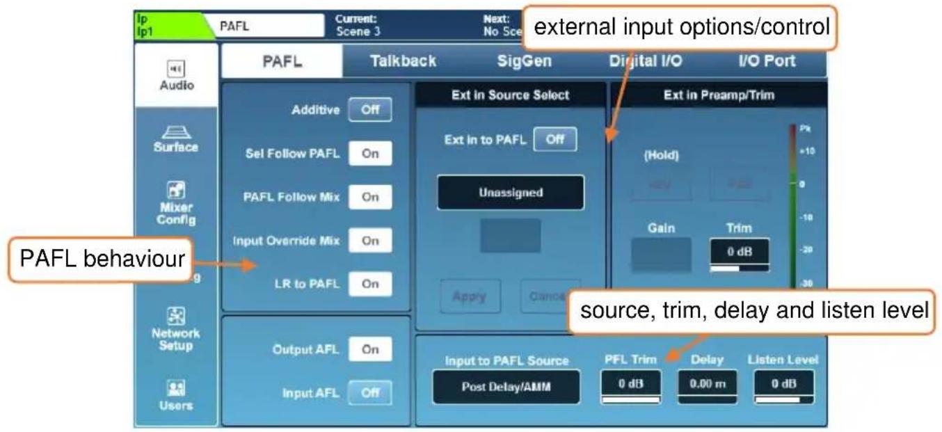
- Touch any button on the left of the screen to turn an option on or off.
Additive (On) = Allows multiple channel strips to be routed to the PAFL bus at once.
Sel Follow PAFL (On) = Pressing a PAFL key will also select ('Sel') a channel. PAFL Follow Mix (On) = When PAFL is active on the master/mix channel strip, the channel being routed to PAFL will follow mix selection.
Input Override Mix (On) = When PAFL is in additive mode, pressing the PAFL key of an input channel unassigns mix channels from the PAFL bus.
Unassigning all input channels reassigns the previously assigned mixes. LR to PAFL (On) = When no other PAFL routing is active, the main LR mix is routed to the PAFL bus.
Output AFL (Off) = Output channels routed to the PAFL bus are pre-fade. (Pre-Fade Listen)
Output AFL (On) = Output channels routed to the PAFL bus are post-fade. (Post/After Fade Listen)
Input AFL (Off) = Input channels routed to the PAFL bus are pre-fade. (Pre-Fade Listen)
Input AFL (On) = Input channels routed to the PAFL bus are post-fade. (Post/After Fade Listen)
Ext in Source Select and Ext in Preamp/Trim –
Use these settings to select an external in socket to feed directly to the PAFL bus. Preamp control will become available when a local or remote preamp has been assigned.
Use the 'Ext in to PAFL' button to switch the external in signal on or off.
This feature is intended for communication between two systems, so it is active even when the PAFL bus is being used to monitor channels.
Input to PAFL Source Point –
Select where in the channel the PAFL signal is sourced from.
Post Preamp = Signal is affected by preamp only
Post PEQ = Also includes DEEP Preamp, HPF, Gate, Insert and PEQ
Post Compressor = Also includes Compressor
Post Delay/AMM = Also includes Channel Delay and AMM
Note that 'Post Preamp' setting does not include DEEP Preamp processing.
This setting determines the behaviour of the 12 segment LED meter when an input is being monitored. It may be different to Chromatic Channel Metering depending on the Input Meter Source setting.
PFL Trim -
The PFL trim attenuates the level of PFL signal routed to the PAFL bus. It does not affect AFL.
PFL Trim = -24dB to 0dB
Delay -
The PAFL delay can be used to align the PAFL bus when, in a live sound environment, the naturally delayed sound from a sound system can be heard at the same time as the otherwise instant signal fed to headphones or monitors, causing phase issues or an audible delay.
PAFL bus delay = 0ms to 682.6ms
Listen Level –
The Listen bus is fed by the PAFL signal and can be patched to an output socket. The Listen Level affects the output level of this bus.
Listen Level = -Inf to +10dB
The Listen Level can also be controlled by the master fader. See the Mixer Role section of this guide for more information.
12.9 Talkback Settings
Talkback is used to enable the engineer to communicate via the audio outputs.
When the 'Talk' key is pressed, the talkback source is routed to all assigned mixes.
The talkback output can also be routed from the I/O screen from the 'Monitor Out' tab. This output respects the 'Talk' switch and is useful for a dedicated talkback speaker or use with a ME system.
Press the 'Setup' screen key, then touch the 'Audio' tab followed by the 'Talkback' tab to view and adjust the talkback settings.
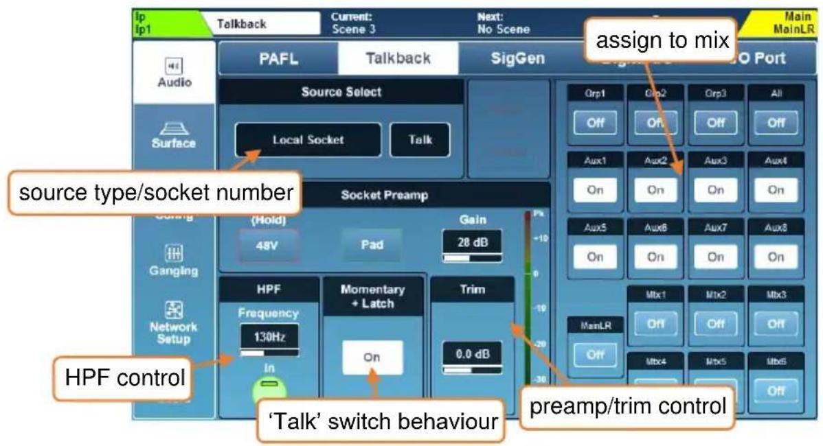
- Source, preamp and trim settings are the same as those used in the Processing/Preamp screen and can be adjusted in exactly the same way.
- Similarly, HPF works in the same way as for any input channel in the Processing/HPF screen.
- Touch the momentary latch 'On' button to enable the 'Talk' key latching mode. When this mode is on, a quick single press of the 'Talk' key switches talkback on or off, though the key will continue to work as in momentary mode if held.
- Touch any mix assign button to switch the talkback feed on or off for that mix.
Note that the local ‘Talk’ socket can be used as an extra input socket. When ‘Talk’ is assigned to an input channel, changing preamp settings in the Processing screen for that channel will also change settings in the Talkback setup and vice versa. The same logic applies when a source other than the local ‘Talk’ socket is assigned as the Talkback source. The HPF and Trim however, are independent.
12.10 Signal Generator
The signal generator can be used to send a signal to a mix for level configuration or used in conjunction with an RTA and a measurement microphone to check the frequency response of a system.
Press the 'Setup' screen key, then touch the 'Audio' tab followed by the 'SigGen' tab to view and adjust the signal generator settings.
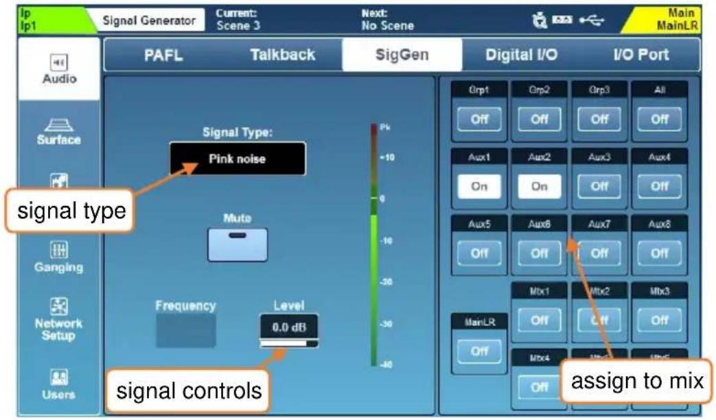
- Touch the 'Signal Type' value to select a type of signal.
Signal Type = Sine, White noise, Pink noise, Band-pass noise
- Touch the 'Mute' button to mute or unmute the signal.
- Touch the 'Frequency' value (where available) and use the touchscreen rotary to adjust.
Frequency = 20Hz to 20kHz
- Touch the 'Level' value and use the touchscreen rotary to adjust.
Level = -72dB to +18dB
- Touch any mix assign button to assign or unassign the signal generator to or from a mix.
The signal generator can also be used by any input channel. Select 'Signal Generator' in 'Source Select' on the Processing/Preamp screen.
12.11 Audio Clock Sync and AES/USB/SQ-Drive Sample Rate
Press the ‘Setup’ screen key, then touch the ‘Audio’ tab followed by the ‘Digital I/O’ tab to see audio clock source, AES and USB/SQ-Drive sample rate options.
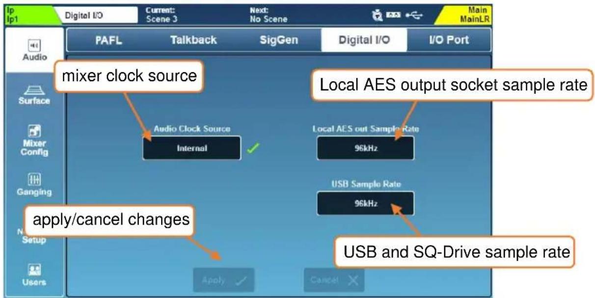
Audio Clock Source –
- Touch the 'Audio Clock Source' value to select a source.
Internal = Sync to the internal audio clock.
SLink = Sync to a digital clock signal being received by the SLink port. I/O Port = Sync to a digital clock signal being received on the port of a connected option card.
- Touch the 'Apply' button to apply changes.
When successfully synchronised, a green tick will be shown to the right of the source selection. When there is no suitable clock being received, a red cross is shown to the right of the source selection and in the SQ title bar and the SQ will ‘fall back’ to using the internal audio clock.
- When using the SQ as a standalone system with or without expansion units, 'Internal' should be selected as the clock source.
- When connecting to another system or 3 ^rd party audio network (such as Dante or Waves), a single clock source on the network should be determined and all other units should synchronise to it, either directly or through connected devices.
The SQ will always run at 96kHz internally, even if the clock source it is synchronised to is running at 48kHz.
i Issues with clocking can result in audible clicks and pops in the audio.
When connecting directly to a Qu, the port the Qu is connected to must be used as the clock source.
Local AES out Sample Rate –
The sample rate of the digital AES output can be changed if required.
- Touch the current sample rate value, then select an option.
AES Output Sample Rate = 44.1kHz, 48kHz, 88.2kHz, 96kHz
- Touch the 'Apply' button to apply any changes.
USB Sample Rate –
The sample rate setting applies to both USB-B and SQ-Drive and can be switched between 96kHz (no sample rate conversion) and 48kHz (sample rate conversion enabled).
Conversion takes place between the core and USB-B or SQ-Drive connection so the SQ will continue to run all processing at 96kHz whichever mode is selected.
i Selecting 48kHz mode will allow recording and playback of up to 32 channels to and from SQ-Drive. For more information, see the SQ-Drive Multitrack Recording and Playback section of this guide.
12.12 I/O Port (Option Cards)
There are multiple option cards available for the SQ's I/O Port. These enable the SQ to interface with 3^rd party audio protocols or can provide an additional SLink port.
Before fitting, check SQ firmware release notes to ensure the option card is supported by the version of firmware currently running on the SQ.
To see and adjust I/O Port settings, press the 'Setup' screen key, then touch the 'Audio' tab followed by the 'I/O Port' tab.
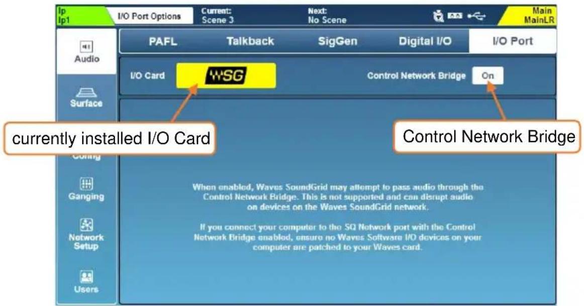
This screen shows information and settings for the option card which is currently connected. It also contains the 'Control Network Bridge' switch.
When the Control Network Bridge is on, the option card is internally connected (bridged) to the SQ's Network port. The Control Network Bridge is for control messaging only, as unlike the SLink port or the ports on Dante and Waves option cards, the SQ's Network port cannot be used for audio connections.
Note that having the Control Network Bridge 'On' can cause issues with certain setups. Details of these potential issues are shown in the bottom half of the screen and should be considered before the network is bridged.
SLink option card –
The SLink Option card provides an additional SLink port to any SQ console. It has exactly the same functionality as the built-in port, but operates independently, allowing for two different protocols to be run on the same system.
The 'Control Network Bridge' switch does not affect the SLink option card as the SLink port is for direct connection to other consoles or expanders using Layer 2 protocols.
Dante option card –
The Dante option card provides a 64x64 channel connection to a Dante network running at either 96kHz or 48kHz.
When patching to/from the I/O Port with a Dante card fitted, you are patching between the SQ core and Dante module. You must then use Dante controller to carry out further patching between the option card module and other devices on the network.
The ‘Control Network Bridge’ can allow a computer connected to the Dante network to also control the SQ using SQ-MixPad or MIDI over TCP/IP, or a computer connected to the SQ’s Network port to run Dante Controller and adjust patching or device settings.
No audio is passed through the SQ's Network port.
Visit the Audinate website (www.audinate.com) to learn more about Dante, and to download software including Dante Controller and Dante Virtual Soundcard (DVS).
Waves option card –
The Waves option card provides a 64x64 channel connection to a Waves SoundGrid network running at either 96kHz or 48kHz.
When patching to/from the I/O Port with a Waves card fitted, you are patching between the SQ core and Waves module. You must then use Waves software (SoundGrid Studio) to carry out further patching between the option card module and the computer or other devices on the network.
The ‘Control Network Bridge’ allows a computer connected to the SoundGrid network to also ‘see’ and control the SQ using SQ-MixPad or MIDI over TCP/IP.
Note that with the Control Network Bridge On, it may be possible to attempt to pass SoundGrid audio through the SQ's Network port, but the system should not be used in this way and any connection which will carry audio should be connected directly to option card ports.
Visit the Waves support website (www.waves.com/support) for more information on Waves SoundGrid and to download the applications and drivers required for use of the Waves option card with your system.
MADI option card –
The MADI option card provides a 64x64 channel connection to other MADI equipment via 2 input and 2 output links. It can run at either 96kHz or 48kHz, with or without redundancy.
When running at 96kHz, up to 32 channels can be used on each input or output link and at 48kHz up to 64 channels can be used on each input output link as follows:
| Mode | Link 1 Input | Link 1 Output | Link 2 Input | Link 2 Output |
| 96kHz | Channels 1-32 | Channels 1-32 | Channels 33-64 | Channels 33-64 |
| 96kHz (Redundant) | Channels 1-32 | Channels 1-32 | Channels 1-32 | Channels 1-32 |
| 48kHz | Channels 1-64 | Channels 1-64 | - | - |
| 48kHz (Redundant) | Channels 1-64 | Channels 1-64 | Channels 1-64 | Channels 1-64 |
The Word Clock BNC on the option card can be set as an input or output and the Sync Source can be Word Clock or either of the input Links.
To clock the SQ to the MADI Sync Source the SQ Audio Clock Source must also be set to 'I/O Port'.
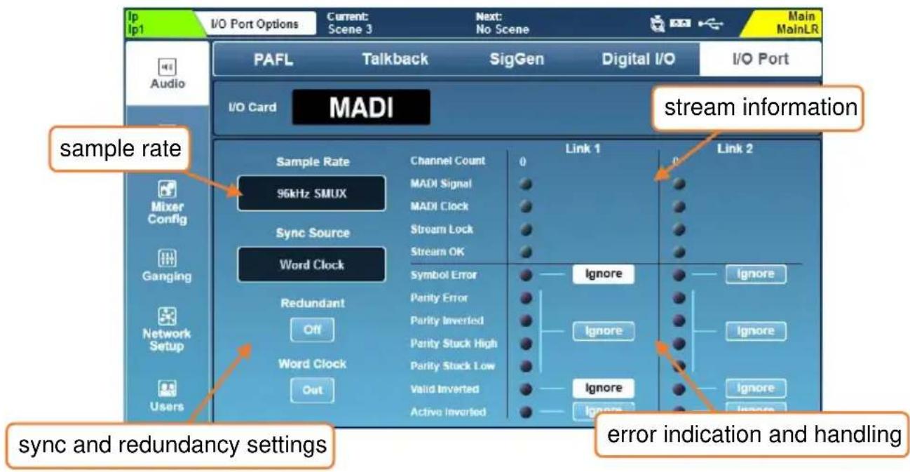
Information on the MADI stream for each Link is displayed to the right of the main settings, including error indication. If an error is detected on the stream, incoming audio will be muted, so an option to ignore these errors is provided for greater compatibility with third party equipment.
Only ignore stream errors when absolutely required and check for integrity of the audio at low level, as an error in the stream could cause full scale digital noise on the outputs.
The SQ MADI option card requires firmware V1.5.2 or later.
12.13 Mixer Role and Master Fader Mode
For quick setup from a known starting point you can select the 'role' of the SQ.
Press the 'Setup' screen key, then touch the 'Mixer Config' tab followed by the 'Role' tab to view options for resetting mix settings and to change the master fader mode.
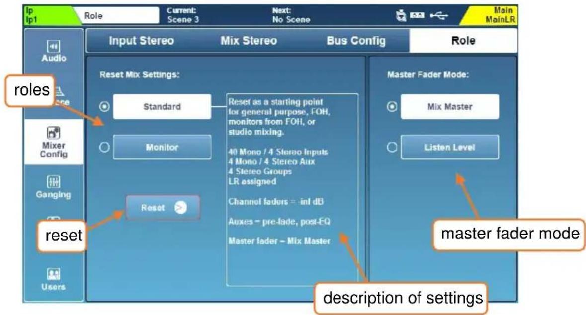
Reset Mix Settings –
Selecting a role for the SQ and touching the ‘Reset’ button will reset the mix. Scenes and libraries are unaffected, though global filters and safes (used when recalling scenes) are ignored, and all safes are cleared.
For details on default settings for different roles, see the Mix/System Reset section.
Master Fader Mode –
The master fader can either be used to control the master send level of the selected mix or the level of the listen bus. Touch either mode button to instantly switch mode.
The listen level can be viewed and adjusted at any time in the PAFL screen. Listen level can also be assigned to a Soft Rotary control on the SQ-6, SQ-7 and SQ-Rack.
In ‘Mix Master’ mode, the blue LR mix key on the surface is illuminated blue when the LR mix is selected.
In ‘Listen Level’ mode, the blue LR mix key on the surface is illuminated red at all times. On the SQ-Rack, the fader at the end of each layer when viewing the faders screen is coloured red and controls listen level.
12.14 DCA Spill
The DCA Spill function allows all members of a DCA to be temporarily displayed across channel strips and layers, in place of the current channel strip layout.
Members are always spilled in listed order with the DCA itself on the last channel strip. Working with channels in a spill state is then the same as when working with the standard channel strip layout.
There are two ways to 'spill' a DCA, either directly or using the 'Spill On Sel' function.
Spill a single DCA –
Assign a SoftKey to spill a specific DCA, or set a Soft Rotary Key to 'Spill' when the Soft Rotary is assigned to 'DCA Level Fader'.
For information on assigning functions to SoftKeys, see the SoftKeys/SoftRotaries section of this guide.
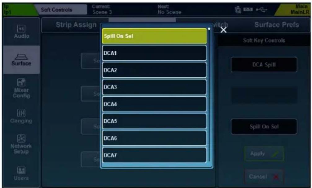
Press the Key to instantly spill the DCA. The SoftKey will flash and the spilled DCA will be shown next to the currently selected mix on screen.
To exit spill, either press the key again, or press the (flashing) 'Sel' key on the DCA channel strip.
Spill on select –
Assign a SoftKey to 'Spill On Sel'. When pressed, it will illuminate to show spill on select is active and a second press will deactivate the function.
When active, pressing the 'Sel' key of any DCA channel strip will spill that DCA. To exit spill, press the (flashing) 'Sel' key on the displayed DCA channel strip.
Deactivating spill on select will automatically exit any current spill.
12.15 Input Ganging
Ganging enables attributes to be linked across multiple input channels. This means changes to linked attributes on one member of the gang affect all other members of that gang at the same time.
The SQ features 8 gangs with up to 12 members in each.
To setup ganging, press the 'Setup' screen key, then touch the 'Ganging' tab.
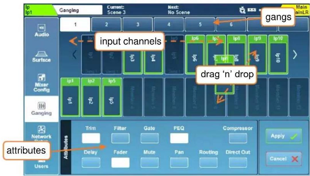
- Select a gang using the numbers at the top of the screen.
- Drag and drop input channels from the channel list to the gang. Touch and drag left and right to see all available channels.
- Touch attribute buttons to switch linked attributes for the selected gang on or off. Linked attributes are indicated with white buttons.
- Touch the apply button to create the gang.
Attributes that can be linked by a gang are as follows:
Trim = Post preamp trim
Filter = HPF in/out and frequency
Gate = All gate parameters
PEQ = All PEQ parameters
Compressor = All compressor parameters
Delay = Channel ms delay
Fader = Input fader master position (i.e. to Main LR)
Mute = Channel mute state
Pan = Channel Pan/Balance to mix
Routing = Assignments and send levels to mix
Direct Out = Direct out level
12.16 Network Setup
For use with any control over Ethernet, such as wireless control or use with MIDI over TCP/IP, the SQ must be connected as a device on a network.
With default settings, the SQ will automatically connect to any network which uses DHCP to assign IP addresses and will be seen by any apps running on devices connected to the same network.
In some situations, it is necessary or preferable to use a static IP address. It is not recommended to use the static settings unless you fully understand the network you are connecting to.
Press the ‘Setup’ screen key, then touch the ‘Network Setup’ tab to view and adjust network settings.
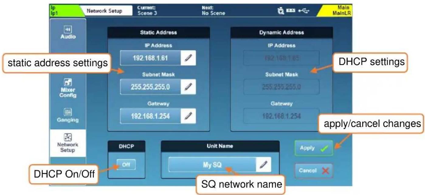
- Touch the DHCP On/Off button to switch DHCP mode on or off. Dynamic address values are displayed when DHCP is enabled and the SQ has been assigned an address. Static settings cannot be adjusted if DHCP mode is on.
- If an address is not assigned via DHCP, the SQ will assign itself an address using an auto-IP function. In this case, an asterisk (‘*’) will be displayed.
- Touch any of the static network values to enter new values.
- Touch the ‘Unit Name’ value to change the name of the SQ (as seen by other devices on the network including apps).
- Touch the 'Apply' or 'Cancel' button to apply or disregard any changes.
When using a wireless router or access point, be sure to connect the SQ's 'Network' port to an available 'LAN' port. The network port 'Lnk' LED on the SQ will illuminate to show network activity.
12.17 User Permissions
Along with the Admin user, SQ can have 10 other users, each with individual permissions, passwords, scene access and user scenes (which are recalled on login).
These users can log in on the SQ itself as well as with any client connected to the SQ remotely, such as the SQ-MixPad and SQ4You remote apps. This means multiple users can be logged in on different devices at the same time.
Press the 'Setup' screen key, then touch the 'Users' tab to setup and configure users.
User setup and permissions can only be carried out when logged in as Admin.
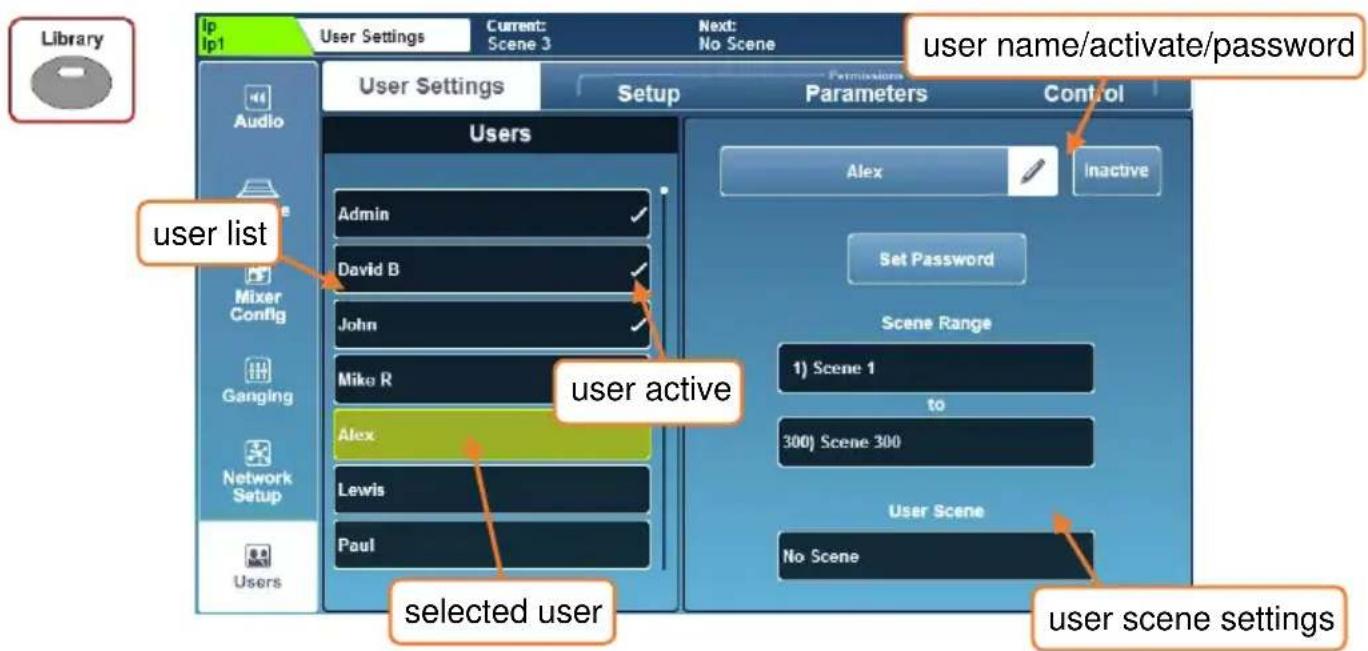
To change user settings and permissions, first select a user from the list on the left. You are now making changes for this user only, so the user list is visible in all tabs, allowing you to quickly compare users and change permissions at any time.
User Settings –
- Touch the user name text box to change the name of the user.
- Touch the ‘Inactive’ button to activate the user (button changes to ‘Active’ and a tick appears in the list).
- Touch the 'Set Password' button to set or change a password for the user. This password is used when logging in as well as when locking the desk.
The Admin user is always active and has unrestricted access to all settings of the SQ.
To remove a password, just set a blank password for the user.
- Use 'Scene Range' to select a range of scenes that the user has access to (the default range is all 300 scenes).
- If required, touch the 'User Scene' value to choose a scene to load when the user logs in.
When logging in as the same user multiple times (such as when the SQ has been powered off at the end of the day, and the same user logs in on the following day), a pop-up is presented to decide whether the SQ either recalls its previous state or the 'User Scene' is reloaded.
User Permissions Library –
With one of the ten users selected, pressing the 'Library' key will display the user permissions library. Factory presets are included as starting points and for quick setup, but you may also store and recall user presets.
- Select a preset and touch 'Recall' to apply permission settings to the currently selected user.
- Touch 'User' to access the user library where you can manage your own presets.
The user permissions library cannot be accessed when the Admin user is selected as the Admin cannot be blocked from using any parameters or features.
Permissions –
Touching the 'Setup', 'Parameters' or 'Control' tabs will display lists of parameters and features that can be set to 'Allow' or 'Block' on a per-user basis.
- Touch the 'Allow'/'Block' button on the right to toggle access.
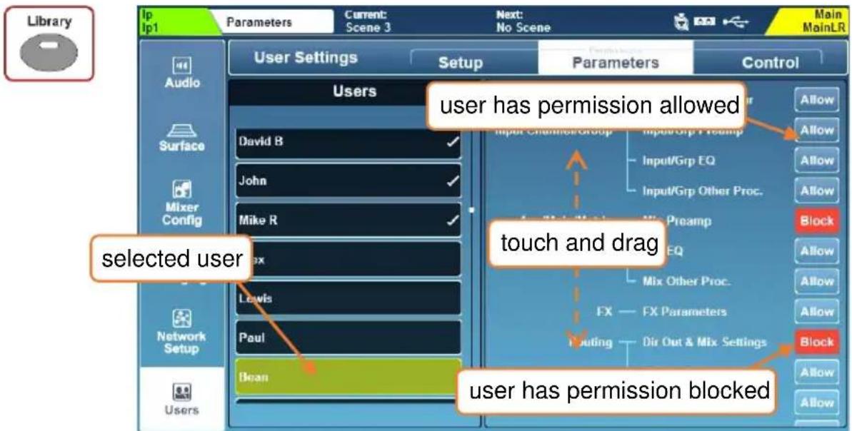
Available User Permissions –
| Setup |
| USB Data Recall |
| USB Data Store |
| USB Data Modify |
| Sync Push |
| Sync Pull |
| Scene Recall |
| Scene Store |
| Scene Modify |
| Cue List Modify |
| Global Filter |
| Channel Safes |
| Scene Preferences |
| Library Recall |
| Library Store |
| Library Modify |
| FX Library Recall |
| FX Library Store |
| FX Library Modify |
| Input Stereo |
| Mix Stereo |
| Bus Config |
| Reset Mix Settings |
| PAFL/Talkback Settings |
| Signal Generator |
| Audio Sync Options |
| USB |
| Surface Strip Assign |
| SQ Control Setup (SQ-Rack) |
| Master Fader Mode |
| Soft Control Setup |
| Meter Settings |
| MIDI Settings |
| Network Settings |
| I/O Port Settings |
| USB Format |
| Parameters |
| Name/Colour |
| Input/Group Preamp |
| Input/Group EQ |
| Input/Group Other Processing |
| Mix Preamp |
| Mix EQ |
| Mix Other Processing |
| FX Parameters |
| DirOut and Mix Settings |
| Mix Assign and Pre/Post |
| DCA/Mute Group Assign |
| Input Patching/Library |
| Output/Insert/FX Patching |
| AMM Setup/Assign |
| AMM Parameters |
| Ganging Setup |
| Control |
| All Screens (SQ-Rack) |
| SQ Control Screen (SQ-Rack) |
| Faders Screen (SQ-Rack) |
| SQ MixPad App Access |
| SQ4You App Access |
| SQ Control App Access |
| Layers B-F* |
| Groups 1-12* |
| Auxes 1-12* |
| FX Sends 1-4* |
| Matrices 1-6* |
| SQ-Drive Playback |
| SQ-Drive Stereo Record |
| SQ-Drive Multitrack Record |
| RTA Settings |
| RTA Follow |
*assignable per layer/mix
13. SQ-Drive and USB-B
SQ-Drive and USB-B use the same patching and sample rate settings. Signal is sent to both simultaneously for recording/streaming, using patching from the SQ to USB output sockets.
The USB input sockets are sourced from USB-B unless playback is active from SQ-Drive. When playing stereo or multitrack audio from SQ-Drive, all USB input sockets are automatically sourced from SQ-Drive. When playback is stopped (not paused), the USB source automatically switches back to USB-B.
There are bandwidth intensive tasks (such as formatting an SQ-Drive or loading a show) that may interrupt use of SQ-Drive or USB-B.
Before recording or playing back audio, both the mode and the sample rate should be set.
Changes to sample rate when a USB-B connection is active may require applications or DAW's to be restarted for correct operation.
The USB-B connection allows 32 inputs and 32 outputs simultaneously at either 96kHz or 48kHz.
SQ-Drive can record or playback up to 16 channels at 96kHz or up to 32 channels at 48kHz.
To change the USB sample rate. Press the 'Setup' screen key then touch the 'Audio' tab followed by the 'Digital I/O' tab.
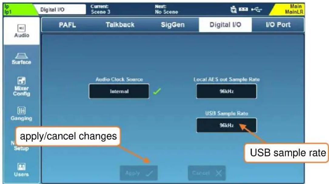
- Touch the 'USB Sample Rate' value to choose between '96kHz' or '48kHz' operation.
13.1 SQ-Drive Stereo Recording and Playback
Press the ‘Utility’ screen key then touch the ‘SQ-Drive’ tab followed by the ‘Stereo’ tab to show the SQ-Drive Stereo record/playback screen.
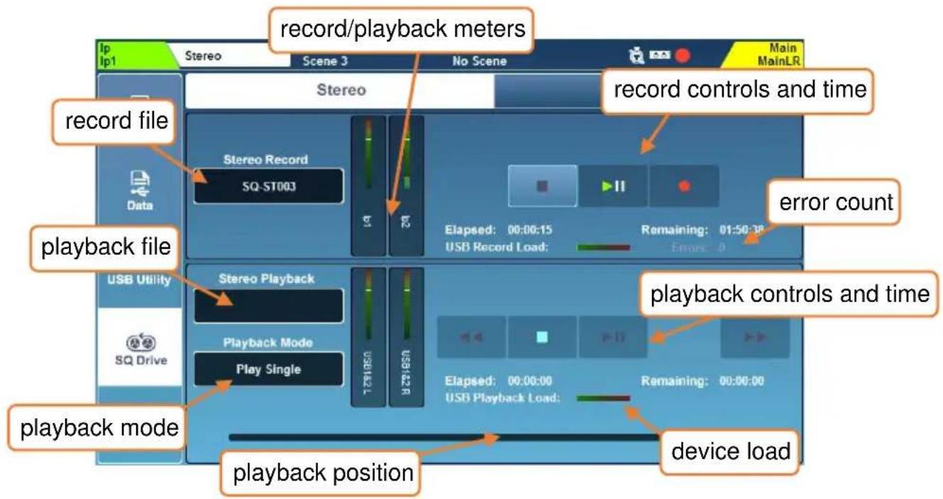
The top half of the screen is for recording and the bottom half is for playback.
Recording –
- Stereo recordings are taken from USB output sockets 1&2. By default, Main LR L and Main LR R are patched to these. The currently patched channels or sockets are labelled below the record meters.
- Press the record button to arm recording, a new 'Stereo Record' file name will appear, the 'Remaining' time value will be displayed and the 'Errors' counter will reset.
- Press the play/pause button to start recording, the 'Elapsed' and 'Remaining' time values will display progress.
- Press the stop button to stop recording.
The device load meter indicates the suitability of the USB device for recording or playback of audio.
The 'Errors' counter increments with any detected writing error.
Playback –
- Stereo playback can be routed to any channel, or multiple channels, by sourcing them from USB input sockets 1&2. The first channels (in numerical order) that USB input sockets 1&2 are patched to are labelled below the playback meters.
- Touch the ‘Stereo Playback’ file name value. Then touch the ‘Playback’ or ‘Recording’ button to view files in each folder (recordings you have made with the SQ are displayed in the ‘Recordings’ folder).
- Touch a track to highlight it.
- Touch the 'Select' button to load the highlighted track.
- Touch the 'Playback Mode' value to select a mode.
Play All = Play all tracks in the folder consecutively.
Play Single = Play the selected track then stop.
Repeat All = Repeatedly play all tracks in the folder consecutively.
Repeat Single = Repeatedly play the selected track.
- Touch the transport buttons to go to the previous or next track, or to stop or play/pause.
- Touch and drag the circular playback position marker to jump to a different point in the track.
Formats and Folders –
SQ-Drive stores stereo recordings to '
These are 96kHz or 48kHz 24bit stereo *.wav files, named sequentially in the order recorded i.e. SQ-ST001.WAV, SQ-ST002.WAV...
Files for stereo playback copied from a computer should be placed in '
These can be mono or stereo, uncompressed PCM *.wav files, 44.1, 48 or 96kHz and 16 or 24-bit.
They must not contain any headers (such as BWF) or data (such as markers).
i Files will be time/date stamped with the time/date of the external device if an instance of SQ-MixPad is connected to the SQ when recording is started.
Length of Recording –
The maximum length of a stereo recording is based on the maximum file size of 4GB, which equates to approximately 2 hrs at 96kHz or 4 hrs at 48kHz.
13.2 SQ-Drive Multitrack Recording and Playback
Press the 'Utility' screen key then touch the 'SQ-Drive' tab followed by the 'Multitrack' tab to show the SQ-Drive multitrack record/playback screen.
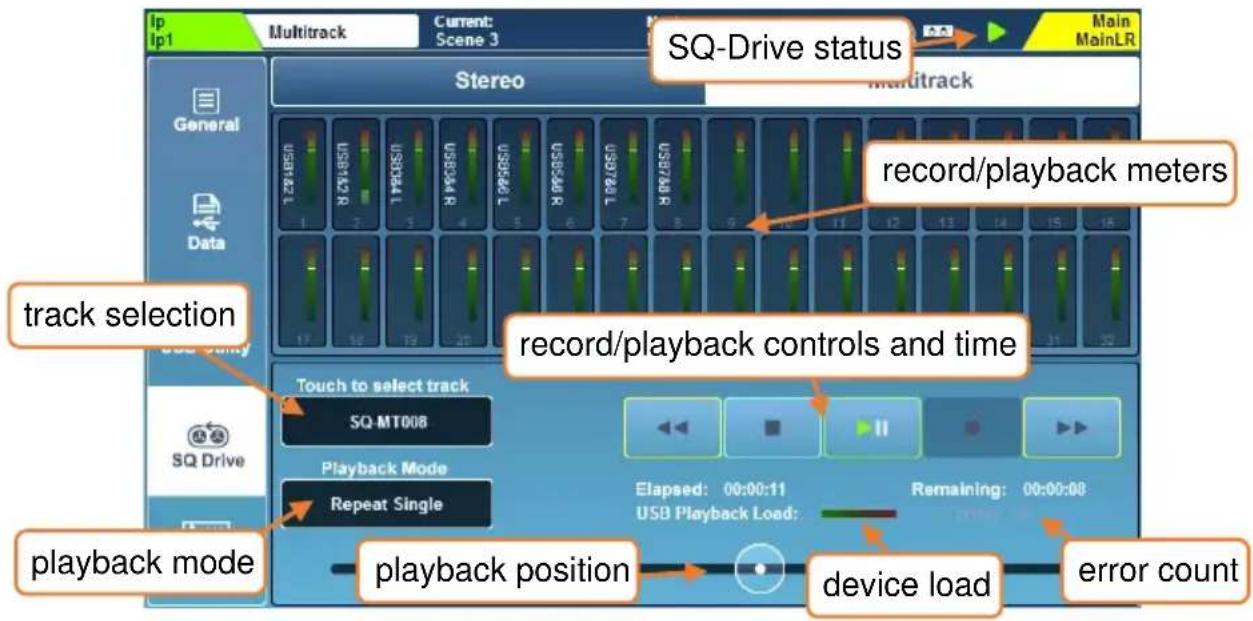
In 96kHz operation the top row of 16 meters is displayed with the bottom row greyed out. When the USB sample rate is set to 48kHz, all 32 meters are shown.
When SQ-Drive is not being used, and during recording, the meters display the outputs from the SQ that have been patched to USB channels. During playback the meters instead show the incoming USB levels and are labelled with the highest numbered channel to which they have been patched.
Meters for USB inputs and outputs can be seen simultaneously in the 'Meters/USB meters' screen.
Recording –
Only USB channels that have been patched to will be recorded. So, to avoid using disk space unnecessarily, patch only the required channels to USB in the I/O screen and leave other USB output sockets unpatched.
- Press the record button to arm recording. A new multitrack file name will appear, the 'Remaining' time value will be displayed and the 'Errors' counter will reset.
- Press the play/pause button to start recording. The ‘Elapsed’ and ‘Remaining’ time values will display progress.
- Press the stop button to stop recording.
i Allow the write process to complete before recording again or removing the device.
The device load meter indicates the suitability of the USB device for recording or playback of audio.
The ‘Errors’ counter increments with any detected writing error.
Not all USB devices are capable of the high bandwidth used by the SQ-Drive multitrack recording feature. For best results when multitrack recording direct to USB, use a high-speed external hard drive rather than a USB stick/pen' drive.
Playback –
Recorded tracks will playback from SQ-Drive on the same USB socket numbers they were recorded from. i.e. If a recording were made where SQ outputs were patched to USB output sockets 3, 5 and 6, then when playing back the recording, USB input sockets 3, 5 and 6 should be patched to SQ inputs.
- Touch the multitrack file name value. Touch a track to select it, then scroll through the list of tracks using the touchscreen rotary if needed.
- Touch the 'Select' button to load the track.
- Touch the 'Playback Mode' value to select a mode.
Play All = Play all tracks in the folder consecutively.
Play Single = Play the selected track then stop.
Repeat All = Repeatedly play all tracks in the folder consecutively.
Repeat Single = Repeatedly play the selected track.
- Touch the transport buttons to go to the previous or next track, or to stop or play/pause.
- Touch and drag the circular playback position marker to jump to a different point in the track.
Formats and Folders –
SQ-Drive stores multitrack recordings to separate folders in the parent folder '
Up to sixteen 96kHz or up to thirty-two 48kHz, 24bit mono uncompressed PCM *.wav files are recorded – with naming based on the USB channel and source channel/socket name e.g. '01KikIn.WAV', '02KikOut.WAV'...
Files for multitrack playback copied from a computer should follow this formatting, naming and folder structure. Files must also be exactly the same size/length.
Files will be time/date stamped with the time/date of the external device if an instance of SQ-MixPad is connected to the SQ when recording is started.
Length of Recording –
The maximum length of a recording is based on a maximum individual file size of 4GB, which equates to approximately 4 hrs at 96kHz or 8 hrs at 48kHz.
13.3 Connecting to a Computer
To stream audio to and from a computer, it needs to be connected to the SQ using a USB-A to USB-B cable.
SQ conforms to USB 2.0 standards, so it is recommended to use a high-speed USB cable. Depending on the environment the system is being used in, it may also be beneficial to use a cable which includes a ferrite bead.
Note that not all USB 3.0 ports are fully backward compatible with USB 2.0 – for best results, it is therefore recommended that a USB 2.0 port is used where available. Where unavailable, USB 3.0 ports utilising xHCI host controller drivers should be avoided as many are known not to support the isochronous transfer method used for streaming audio.
Sample rate –
The SQ USB sample rate should be set before any programs or apps accessing the USB-B connection are used.
To connect SQ to a mac -
The SQ is Core Audio compliant so drivers are not required.
Connect the SQ via USB and it will appear as both an audio and a MIDI device.
To connect SQ to a Windows PC –
Visit the Allen & Heath website (www.allen-heath.com) to download the latest SQ Windows ASIO/WDM drivers.
Follow the instructions to install the drivers before connecting the SQ.
Routing -
- It is important to note when patching, that outputs from the computer are USB input sockets on the SQ and USB output sockets from the SQ are inputs on the computer.
- By default, SQ input channels 47 and 48 are sourced from USB channels 1 and 2, and USB output channels 1 and 2 are fed from the Main LR mix, though all USB patching is fully assignable.
- When using WDM drivers to utilise the SQ for Windows system/default sound, only USB channels 1 and 2 are used on the SQ. To make use of all 32 input and 32 output channels, the ASIO driver must be used with a compatible program.
- When selecting the SQ as the default output audio device on a mac, USB channels 1 and 2 are used by default, though this can be changed in the Audio MIDI setup.
14. MIDI and DAW Control
When connected to a computer either via USB or TCP/IP, the SQ sends and receives MIDI control messages.
These can be broken down into two sets of bi-directional messages. Those that are used to control the SQ, and those used to control external software or equipment.
Please refer to the separate SQ MIDI Protocol document, available from www.allen-heath.com for full details on all SQ MIDI communication.
14.1 MIDI Channel and MMC
Press the ‘Utility’ screen key, then touch the ‘General’ tab followed by the ‘MIDI’ tab to view and adjust the MIDI channel setting. This screen also displays MMC (MIDI Machine Control) buttons for control of computer sequencers and DAW’s.
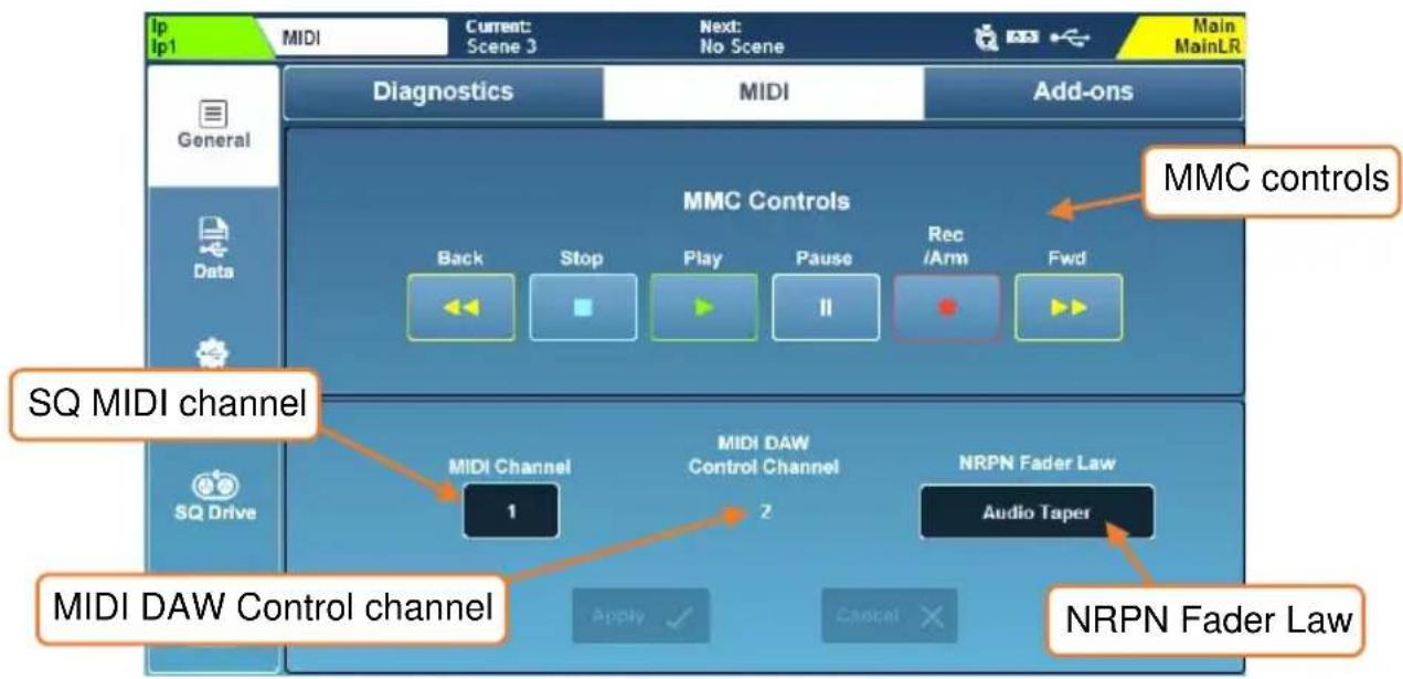
- Touch the 'MIDI Channel' value and use the touchscreen rotary to adjust.
- Touch the ‘NRPN Fader Law’ value to select the fader law used for control to and from SQ channel levels.
Linear Taper = High resolution linear control for automation Audio Taper = External MIDI faders match SQ faders
- Touch the 'Apply' or 'Cancel' buttons to apply or disregard changes.
The channel used for DAW Control (and therefore all MIDI fader strips) is always one more than the MIDI Channel the rest of the SQ is set to. To use MIDI channel 1 for the DAW Control Channel, set the main SQ MIDI channel to 16.
- Touching any of the MMC Controls sends standard MMC transport messages to all channels. These are also translated by the DAW control driver to specific transport messages for the control surface emulation being used.
14.2 MIDI Fader Strips
The SQ has 32 available MIDI fader strips that can be assigned anywhere in the fader strip layers.
These transmit standard MIDI messages over USB and TCP/IP when ‘Mute’, ‘Sel’ or ‘PAFL’ keys are pressed, or when the fader strip fader is adjusted. They also respond to the same messages.
- Messages can be used as-is, and 'learnt' by software for control.
- By default, these messages are transmitted on MIDI Channel 2.
- Pressing a key will send a note on followed by a note off, moving a fader sends a continuous change message.
| SQ MIDI Fader Strip Control | MIDI message |
| Mute keys 1 to 32 | Note On/Off 0 (C-1) to 31 (G1) |
| Sel keys 1 to 32 | Note On/Off 32 (G#1) to 63 (Eb4) |
| PAFL keys 1 to 32 | Note On/Off 64 (E4) to 95 (B6) |
| Faders 1 to 32 | CC 00 to CC 31 |
14.3 DAW Control
MIDI fader strips can be used with the Allen & Heath MIDI Control application. This translates the messages from the MIDI strip and emulates standard control surface messages for use with a DAW. Channel names are also sent from the DAW and applied to the MIDI channel strips.
Visit www.allen-heath.com to download the latest version of Allen & Heath MIDI Control and view instructions for installation and correct setup.
It is worth noting that SoftKeys can also be assigned to send MMC messages or ‘Bank Up’, ‘Bank Down’ messages, and using these will also update MIDI channel strip naming.
Only the MIDI fader strips, MMC controls and specific SoftKey assignments are used for DAW control surface emulation. Other physical controls (such as EQ rotaries) continue to control the selected channel in the SQ.
14.4 MIDI from Soft Controls
Soft Rotaries and Soft Rotary keys can be used to transmit MIDI messages over USB and TCP/IP, including note on/off, CC absolute, CC relative, MMC and program change messages.
This allows them to be used for control external equipment or software.
See the SoftKeys/SoftRotaries section for details.
15. Automatic Microphone Mixing (AMM)
Automatic Microphone Mixing provides automated level control of multiple microphone channels. It is designed for use in multichannel speech applications such as conferences, panel discussions, theatre or broadcast.
The AMM's in SQ use the D-Classic gain sharing algorithm to increase the level of active channels whilst simultaneously decreasing the levels of any other assigned channels. Priority levels can be set to prioritise certain AMM slots over others.
SQ features 2x DEEP AMM's with up to 24 channels each, these can be combined for use as a single 48 channel AMM and use a DEEP embedded gain stage in the channel, so no latency is added.
i AMM is not intended for use with instruments or signal sources other than speech.
15.1 AMM Input Assign
Any input channel can be assigned to an AMM. Due to AMM being embedded directly in the channel (post-delay/pre-fader), PFL can be affected by the changes in level. Therefore, we recommend that channels are set up before being added to an AMM.
To assign input channels, press the 'Utility' screen key, then touch the 'AMM' tab followed by the 'Input Assign' tab.
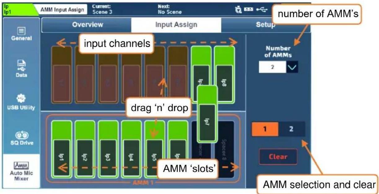
flowchart
graph TD
    A["Input channels"] --> B["drag 'n' drop"]
    B --> C["AMM 'slots'"]
    C --> D["AMM selection and clear"]
    style A fill:#f9f,stroke:#333
    style B fill:#ccf,stroke:#333
    style C fill:#cfc,stroke:#333
    style D fill:#fcc,stroke:#333
The top part of the screen shows the available input channels and at the bottom are available AMM slots.
Select either ‘2’ (2 x 24 channel) or ‘1’ (1 x 48 channel) AMM from the ‘Number of AMMs’ dropdown.
Assigning/unassigning channels –
- If using 2 AMM's, use the AMM selection buttons to choose which AMM to display.
- Touch and drag left or right to show all input channels and AMM slots.
- Touch and drag input channels from the top to AMM slots at the bottom to assign a channel.
i Input channels can be freely assigned to any AMM slot, they do not need to be assigned sequentially.
Dropping channels into a slot that already has a channel assigned, automatically unassigns the previously assigned channel.
- Touch and drag channels from assigned slots back to the top to unassign.
- Touch the 'Clear' button to clear all channels from the selected AMM.
15.2 AMM Overview
Press the 'Utility' screen key, then touch the 'AMM' tab followed by the 'Overview' tab.
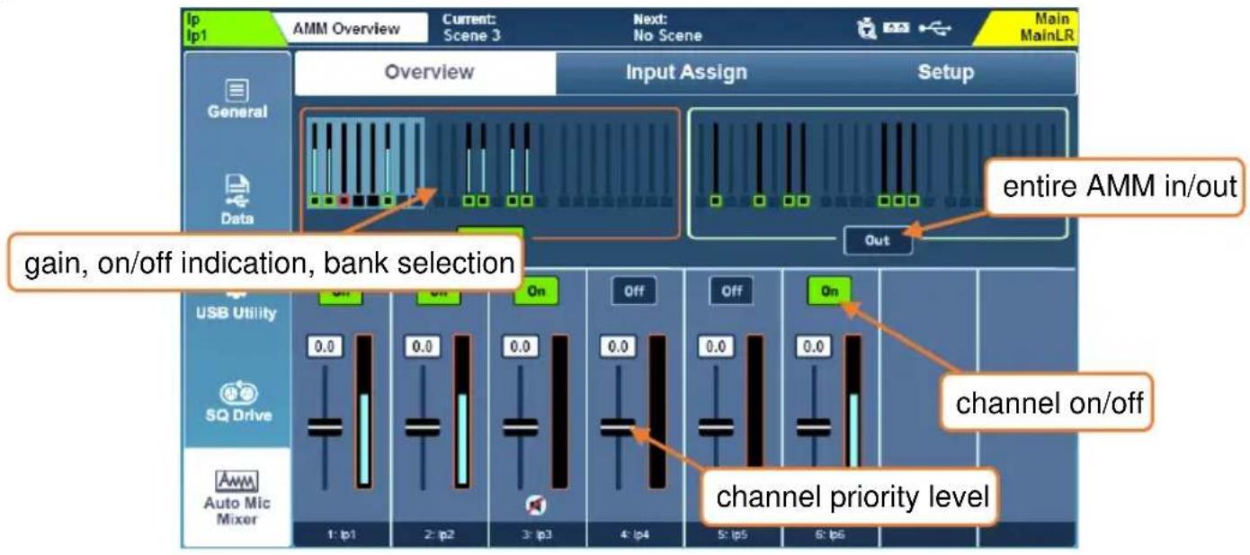
The top part of the screen displays an overview of all AMM slots, with the metering showing gain being applied to channels and indication of whether channels have AMM switched on.
- Touch an AMM 'In/Out' button to switch all AMM channels in or out.
If a channel has AMM switched on and is assigned to an AMM which has all channels switched in, this is indicated in the channel overview shown in the 'Processing' screen.
- Touch a block of 8 AMM channels at the top to display these in the bottom half of the screen.
- Touch a slot 'On/Off' button to add or remove the assigned channel from the AMM. Channels have AMM automatically set to 'On' when they are assigned.
- Touch a slot fader and adjust using the touchscreen rotary to increase or decrease gain, and therefore slot priority in the AMM calculation.
Priority level = -15 to +15
15.3 AMM Setup
Press the 'Utility' screen key, then touch the 'AMM' tab followed by the 'Setup' tab.
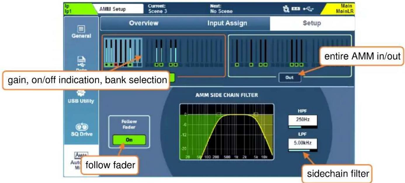
Like the ‘Overview’ screen, this displays an overview of all AMM slots, with gain metering and indication of whether or not channels have AMM switched on.
- Touch an AMM 'In/Out' button to switch all AMM channels in or out.
- Touch the gobal Follow Fader 'On' button to choose whether the channel contribution to side chain is affected by channel fader position.
- Touch High Pass Filter or Low Pass Filter frequency values and adjust using the touchscreen rotary to filter unwanted frequencies from the side chain.
$$ \begin{array}{l} \text {HPF = 20Hz to 5kHz} \ \text {LPF = 120Hz to 20kHz} \end{array} $$
The AMM side chain is fed from the channel at the post-HPF point, and automated gain is applied at the post-delay point.
16. Add-ons
Optional add-ons for the SQ are available to purchase, allowing customisation of each unit through the addition of special processing and DEEP models.
To ensure the latest units and models are available, install the latest version of firmware.
Press the 'Utility' screen key, then touch the 'General' tab followed by the 'Add-ons' tab.
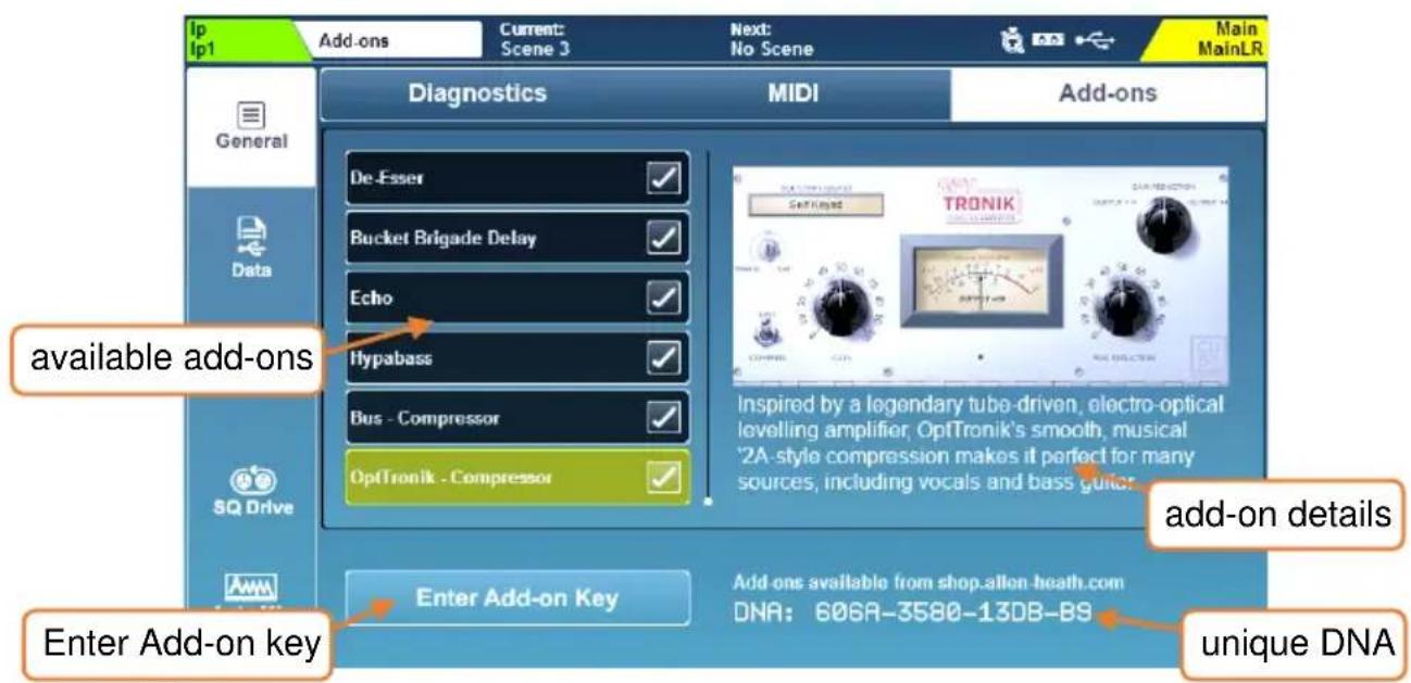
Available add-ons for the SQ are shown to the left, touch to display more information and use the touchscreen rotary to scroll through.
For more detailed information and audio samples of any plugin, visit allen-heath.com.
Activating an add-on –
- Note the serial number and unique DNA for the SQ and visit shop.allen-heath.com to purchase add-ons and then generate a unique key.
- Touch 'Enter Add-on Key' then enter the 16-character key from the shop and touch 'OK' to activate.
Keys are unique to each SQ unit, and only ever need to be entered once. They will not need to be re-entered when updating firmware or after a system reset.
17. Mix/System Reset
17.1 Reset Mix Settings
The SQ has multiple ‘Reset Mix Settings’. These are used to ‘zero the desk’ for different uses.
This will clear the current state of the SQ, but does not affect stored Scene or Library data, so save the current settings
Press the 'Setup' screen key, then touch the 'Mixer Config' tab followed by the 'Role' tab.
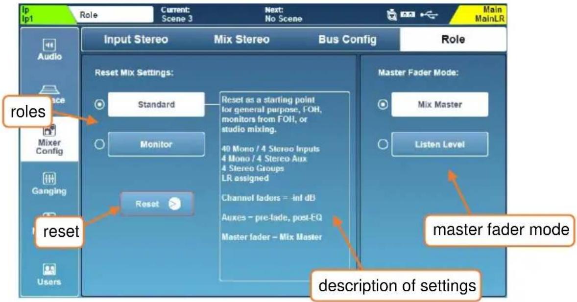
Select an operating role and information on default settings will be displayed. Touch the 'Reset' button to reset the mix with these settings.
Global filters are ignored and safes are all switched off when mix settings are reset.
The Master Fader Mode allows you to choose whether the master fader controls the master send level of the selected mix, or the level of the listen bus. For more information see the Mixer Role section.
| Routing | Setting |
| Input Channels | 40 mono (1-40) then 4 stereo (ST1, ST2, ST3, USB) |
| Input Sources | 1-to-1 (Local) then unassigned then stereo (Local, as labelled) |
| Mix Bus Configuration | Mix 1-4 (Aux mono), Mix 5-8 (Aux stereo), Mix 9-12 (Group stereo) |
| LR Assign | All inputs and groups assigned |
| Aux assign and send | Inputs to all Aux, Pre-Fade, Post-EQ |
| Local Output patching (Aux) | 1-4 (Aux1-4), 5-10 (Aux5-7) |
| Local Output patching (Main) | 11-12 (Main L-R) |
| Local Output patching (Mtx) | A & B (Mtx1), 13-14 (Mtx1), 15-16 (Mtx2) |
| AES output | Main LR |
| SLink Inputs | Unassigned |
| SLink Outputs | Unassigned |
| SQ to USB | Main LR to 1-2, then 1-to-1 direct outs |
| USB to SQ | USB 1-2 to input channel 47-48 |
| Processing type | Setting |
| 48v | All off |
| Preamp gain | +28dB |
| HPF | Out/100Hz |
| Gate | Out/-30dB |
| Insert | Out |
| PEQ | In/Flat |
| GEQ | In/Flat |
| Compressor | Out/3:1/-9dB |
| Pan | Centred |
| Control | Setting |
| SoftKeys 1-6 | Mute Groups 1 to 6 |
| SoftKey 7 | Unassigned |
| SoftKey 8 | Global Tap Tempo |
| SoftKeys 9-16 | Unassigned |
| SoftRotaries | Unassigned |
| Master Fader Mode | Mix Master |
| FX unit | Setting |
| 1 | EMT 250 reverb/FX1Snd/FX1Rtn |
| 2 | Hall 480 reverb/FX2Snd/FX2Rtn |
| 3 | Stereo Tap Vocal Delay/FX3Snd/FX3Rtn |
| 4 | ADT Classic/FX4Snd/FX4Rtn |
| 5-8 | Empty/Unpatched |
| Sends | Level |
| Input to MainLR | -inf |
| FX return channels to LR | 0dB |
| Main LR master | 0dB |
| Aux master | 0dB |
| Group master | -inf |
| FX master | 0dB |
| Routing | Setting |
| Input Stereo | 48 mono (1-48) |
| Local Input patching | 1-to-1 (as labelled), then unassigned to 48 |
| Mix Bus Configuration | Aux 1-6 (mono), Aux 7-12 (stereo) |
| LR Assign | All inputs unassigned |
| Aux assign and send | Inputs to all Aux, Post-Fade, Post-Delay |
| Local Output patching (Aux) | 1-to-1 for mono then sequential stereo |
| Local Output patching (Listen M) | 12 |
| Local Output patching (PAFL) | A & B |
| AES output | Main LR |
| SLink Inputs | Unassigned |
| SLink Outputs | Mixes 1-to-1, then Main LR on last 2 sockets. |
| SQ to USB | Unassigned |
| USB to SQ | Unassigned |
| Processing type | Setting |
| 48v | All off |
| Preamp gains | +28dB |
| HPFs | Out/100Hz |
| Gates | Out/-30dB |
| Inserts | Out |
| PEQs | In/Flat |
| GEQs | In/Flat |
| Compressors | Out/3:1/-9dB |
| Pans | Centred |
| Control | Setting |
| SoftKeys 1-8 | Mute Groups 1 to 8 |
| SoftKeys 9-16 | Unassigned |
| SoftRotaries | Unassigned |
| Master Fader Mode | Listen Level |
| FX unit | Setting |
| 1-4 | EMT 250 reverb/FXSnd 1-4/FXRtn 1-4 |
| 5-8 | Empty/Unpatched |
| Send type | Level |
| Input channels | 0dB |
| FX return channels | 0dB |
| Main LR master | 0dB |
| Aux master | 0dB |
| Group master | -inf |
| FX master | 0dB |
17.2 System Reset
To perform a full system reset on an SQ-5, SQ-6 or SQ-7, hold the EQ 'In' and 'HF' keys when powering on the unit.
To perform a full system reset on an SQ-Rack, hold the 'Library' and Layer 'A' keys when powering on the unit.
This will clear all mix settings and all saved data, including Shows/Scenes and Libraries, and will revert the SQ to its initial state.
Before you carry out a system reset, back-up any data you wish to keep using a USB device or SQ-MixPad.
See the Data transfer (USB/MixPad) section for more information on storing data.
i System resets do not remove add-ons.
17.3 Fader Calibration
Occasionally faders can become misaligned or behave incorrectly, this can happen for many reasons and is usually nothing to be concerned about. However, it may necessitate a re-calibration.
1) Press the 'Utility' screen key, then touch the 'General' tab followed by the 'Calibration' tab.
2) Touch the 'Calibrate' button and follow the on-screen instructions, positioning the faders at +10dB, 0dB, -10dB, -30dB and -inf when prompted.
18. Block Diagrams
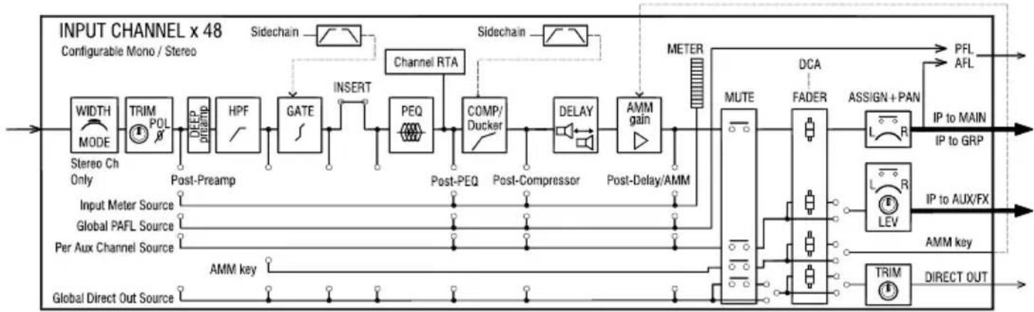
flowchart
graph LR
    A["Input Channel x 48"] --> B["MODE"]
    B --> C["STRIM POL"]
    C --> D["Deep preamp"]
    D --> E["HPF"]
    E --> F["GATE"]
    F --> G["INSERT"]
    G --> H["Channel RTA"]
    H --> I["PEQ"]
    I --> J["COMP/Ducker"]
    J --> K["Post-Compressor"]
    K --> L["DELAY"]
    L --> M["AMM gain"]
    M --> N["METER"]
    N --> O["MUTE"]
    O --> P["FADER"]
    P --> Q["ASSIGN + PAN"]
    Q --> R["PFL AFL"]
    Q --> S["IP to MAIN"]
    Q --> T["IP to GRP"]
    U[" Stereo Ch Only "] --> V[" Input Meter Source "]
    V --> W[" Global PAFL Source "]
    W --> X[" Per Aux Channel Source "]
    X --> Y[" AMM key "]
    Y --> Z[" Global Direct Out Source "]
    AA[" Sidechain "] --> AB[" Sidechain "]
    AB --> AC[" Sidechain "]
    AD[" MUTE "] --> AE[" FADER "]
    AE --> AF[" ASSIGN + PAN "]
    AF --> AG[" IP to MAIN "]
    AF --> AH[" IP to GRP "]
    AI[" FADER "] --> AJ[" L R LEV "]
    AK[" ADMER "] --> AL[" TRIM "]
    AL --> AM[" DIRECT OUT "]
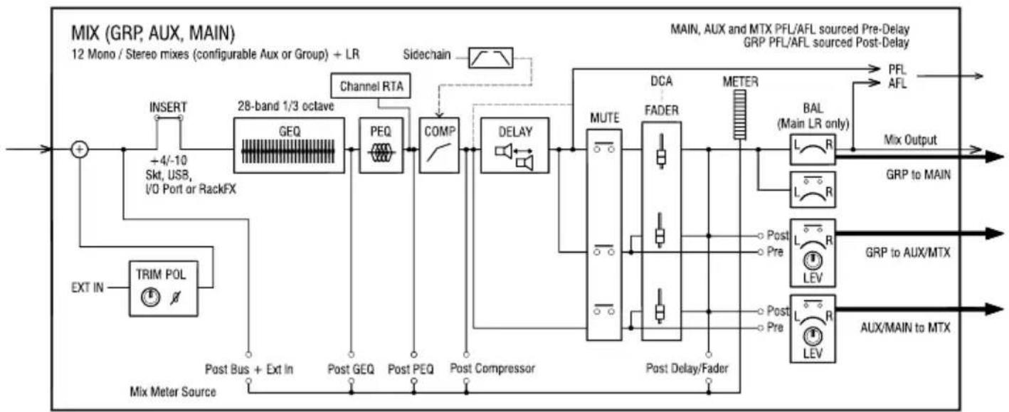
flowchart
graph LR
    A["EXT IN"] --> B["TRIM POL"]
    B --> C["28-band 1/3 octave GEQ"]
    C --> D["PEQ"]
    D --> E["COMP"]
    E --> F["DELAY"]
    F --> G["MUTE"]
    G --> H["DCA FADER"]
    H --> I["METER"]
    I --> J["BAL (Main LR only)"]
    J --> K["PFL AFL"]
    K --> L["Mix Output"]
    M["INSERT"] --> N["28-band 1/3 octave GEQ"]
    N --> O["PEQ"]
    O --> P["COMP"]
    P --> Q["DELAY"]
    Q --> R["MUTE"]
    R --> S["DCA FADER"]
    S --> T["METER"]
    T --> U["BAL (Main LR only)"]
    U --> V["PFL AFL"]
    V --> W["Mix Output"]
    X["Post Bus + Ext In"] --> Y["Post GEQ"]
    Y --> Z["Post PEQ"]
    Z --> AA["Post Compressor"]
    AA --> AB["Delay/Fader"]
    AB --> AC["Post Delay/Fader"]
    AC --> AD["Post Pre"]
    AD --> AE["Post Pre"]
    AE --> AF["Post Delay/Fader"]
    AF --> AG["Post Delay/Fader"]
    AG --> AH["Post Pre"]
    AH --> AI["Post Pre"]
    AI --> AJ["Post Delay/Fader"]
    AJ --> AK["Post Delay/Fader"]
    AK --> AL["Post Pre"]
    AL --> AM["Post Pre"]
    AM --> AN["Post Delay/Fader"]
    AN --> AO["Post Delay/Fader"]
    AO --> AP["Post Pre"]
    AP --> AQ["Post Pre"]
    AQ --> AR["Post Delay/Fader"]
    AR --> AS["Post Delay/Fader"]
    AS --> AT["Post Pre"]
    AT --> AU["Post Pre"]
    AU --> AV["Post Delay/Fader"]
    AV --> AW["Post Delay/Fader"]
    AW --> AX["Post Pre"]
    AX --> AY["Post Pre"]
    AY --> AZ["Post Delay/Fader"]
    AZ --> BA["Post Delay/Fader"]
    BA --> BB["Post Pre"]
    BB --> BC["Post Pre"]
    BC --> BD["Post Delay/Fader"]
    BD --> BE["Post Delay/Fader"]
    BE --> BF["Post Pre"]
    BF --> BG["Post Pre"]
    BG --> BH["Post Delay/Fader"]
    BH --> BI["Post Delay/Fader"]
    BI --> BJ["Post Pre"]
    BJ --> BK["Post Pre"]
    BK --> BL["Post Delay/Fader"]
    BL --> BM["Post Delay/Fader"]
    BM --> BN["Post Pre"]
    BN --> BO["Post Pre"]
    BO --> BP["Post Delay/Fader"]
    BP --> BQ["Post Delay/Fader"]
    BQ --> BR["Post Pre"]
    BR --> BS["Post Pre"]
    BS --> BT["Post Delay/Fader"]
    BT --> BU["Post Delay/Fader"]
    BU --> BV["Post Pre"]
    BV --> BW["Post Pre"]
    BW --> BX["Post Delay/Fader"]
    BX --> BY["Post Delay/Fader"]
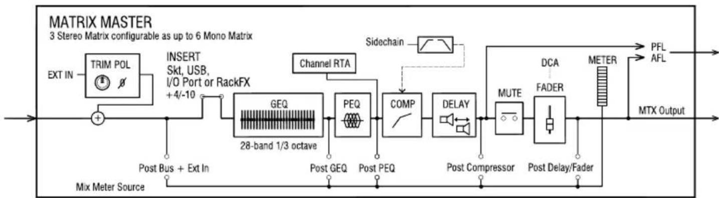
flowchart
graph LR
    A["TRIM POL"] --> B["+"]
    B --> C["28-band 1/3 octave"]
    C --> D["GEQ"]
    C --> E["PEQ"]
    C --> F["COMP"]
    C --> G["DELAY"]
    D --> H["Channel RTA"]
    E --> I["Sidechain"]
    F --> J["Post Compressor"]
    G --> K["MUTE"]
    K --> L["Post Delay/Fader"]
    L --> M["METER"]
    M --> N["PFL"]
    M --> O["AFL"]
    M --> P["MTX Output"]
    Q["EXT IN"] --> B
    R["INSERT Skt, USB, I/O Port or RackFX +4/-10"] --> C
    S["Post Bus + Ext In"] --> C
    T["Mix Meter Source"] --> C
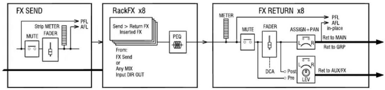
flowchart
graph LR
    A["FX SEND"] --> B["MUTE"]
    B --> C["Strip METER FADER"]
    C --> D["PFL AFL"]
    A --> E["RackFX x8"]
    E --> F["PEQ"]
    F --> G["From: FX Send or Any MIX Input DIR OUT"]
    E --> H["Send > Return FX Inserted FX"]
    H --> I["PEQ"]
    I --> J["METER"]
    J --> K["MUTE"]
    K --> L["FADER"]
    L --> M["DCA"]
    M --> N["Post Pre"]
    L --> O["ASSIGN+PAN"]
    O --> P["PFL AFL in-place Ret to MAIN"]
    O --> Q["Ret to GRP"]
    H --> R["PEQ"]
    R --> S["REVIEW"]
    H --> T["REVIEW"]
    U["FX RETURN x8"] --> V["REVIEW"]
    V --> W["PFL AFL in-place Ret to MAIN"]
    V --> X["Ret to GRP"]
    V --> Y["Ret to AUX/FX"]

flowchart
graph LR
    A["TALKBACK"] --> B["HPF"]
    B --> C["PR"]
    C --> D["Press to TALK"]
    D --> E["SIG GEN"]
    E --> F["MUTE"]
    F --> G["LEV"]
    G --> H["Output"]
    style A fill:#f9f,stroke:#333
    style E fill:#ccf,stroke:#333
    style F fill:#cfc,stroke:#333
    style G fill:#fcc,stroke:#333

flowchart
graph LR
    A["EXT IN"] --> B["TRIM POL"]
    B --> C["-24dB 0dB PFL TRIM (AFL not affected)"]
    C --> D["Listen Level"]
    D --> E["+"]
    E --> F["+"]
    F --> G["+"]
    G --> H["PAFL Meter"]
    H --> I["Listen L/R/M"]
    I --> J["Meters RTA"]
    J --> K["PAFL L/R"]
    K --> L["Feedback to Delay"]
    L --> M["Linked DELAY"]
    M --> N["+"]
    N --> O["+"]
    O --> P["+"]
    P --> Q["+"]
    Q --> R["+"]
    R --> S["+"]
    S --> T["+"]
    T --> U["+"]
    U --> V["+"]
    V --> W["+"]
    W --> X["+"]
    X --> Y["+"]
    Y --> Z["+"]
19. Specifications
Mic/Line Inputs
| Input Sensitivity | -60 to +0dBu |
| Switchable Pad | -20dB |
| Analogue Gain | 0dB to +60dB, 1dB steps |
| Maximum Input Level | +30dBu |
| Input Impedance | >5kΩ |
| THD+N, Unity gain 0dB | 0.002% -92dBu (20Hz-20kHz, AES Direct Out, @0dBu 1kHz) |
| THD+N, Mid gain +30dB | 0.003% -91dBu (20Hz-20kHz, AES Direct Out, @-30dBu INPUT 1kHz) |
| Phantom Power | +48V (+3V / -2V) |
Stereo Line Inputs
| ST1, ST2 connectors | Balanced, 1/4" TRS jack |
| ST3 connector | Unbalanced, stereo 3.5mm Mini Jack |
| Input Sensitivity (ST1, ST2 / ST3) | Nominal +4dBu ST1, ST2 / 0dBu ST3 |
| Trim | +/-24dB |
| Maximum Input Level (ST1, ST2 / ST3) | +22dBu / +18dBu |
| Input Impedance | >7kΩ |
Outputs 1-12/14/16
| Outputs A and B | Balanced 1/4" TRS Jack |
| Source | Patchable |
| Output Impedance | <75Ω |
| Nominal Output | +4dBu = 0dB meter reading |
| Maximum Output Level | +22dBu |
| Residual Output Noise | -90dBu (muted, 20Hz-20kHz) |
AES Digital Output
Balanced XLR, fully recallable
| Balanced XLR 2 channel,96kHz sampling rate (Default with SRC Bypassed)Switchable output sample rates,44.1kHz/ 48kHz/ 88.2kHz/(96kHz)2.5Vpp balanced terminated 110Ω |
SLink Connection
dSnake mode (48kHz devices)
dx mode (96kHz devices)
gigaACE/GX mode (96kHz devices)
Inputs
Outputs
Sync/SRC
Neutrik etherCON (RJ45)
40 input 20+40(ME) output channels
32 input 32 output channels
128 input 128 output channels
Fully Patchable
Fully Patchable
Assignable as audio clock source, 48kHz<>96kHz SRC
I/O Port
Inputs
Outputs
Sync/SRC
Multi-channel IO option module
Fully Patchable
Fully Patchable
Assignable as master audio sync
System
Dynamic Range
Frequency Response
Headroom
Internal operating Level
THD+N, Mic/Line routed to Main L/R Out
dBFS Alignment
Meter Calibration
Main Meter Type
Channel Meter Type
Peak Indication
Sampling Rate
Bit Depth
Latency
Measured balanced XLR in to XLR out, 0dB gain, 0dBu input
112 dB
+0/-0.5dB 20Hz to 20kHz
+18dB
0dBu
Unity gain faders@0dB, 0.006%, -84dBu (20 - 20kHz)
+18dBu = 0dBFS (+22dBu at XLR output)
0dB meter = -18dBFS (+4dBu at XLR out)
2 x 12 segment, fast (peak) response
Chromatic Channel Metering, fully programmable colour/brightness
-3dBFS (+19dBu at XLR out), multi-point sensing
96kHz
Uses XCVI core custom bit widths in algorithms, up to 96bits
<0.7mS, Local Mic Input to Main L/R
Operating Temperature Range
Mains Power
Max Power Consumption
SQ-Rack / SQ-5 / SQ-6 / SQ-7
0 deg C to 40 deg C (32 deg F to 104 deg F)
100-240V AC, 50/60Hz
75W / 75W / 90W / 110W
Input Processing
Source
CH1-48
USB Global Source
Fully patchable
SQ-Drive or USB-B Streaming
Polarity
Trim
High Pass Filter
Insert (Pre EQ/Comp)
Delay
Normal/Invert
-24 to +24dB
12/18/24dB per octave 20Hz – 2kHz
Fully Patchable
Up to 341ms
Gate
Sidechain filter
Threshold / Depth
Attack / Hold / Release
Patchable Sidechain
Hi-pass (20-5k), Band-pass (120-10k), Lo-pass (120-20k)
-72dBu to +18dBu / 0 to 60dB
50μs to 300ms / 10ms to 5s / 10ms to 1s
PEQ
Band 1, Band 4
Band 2, Band 3
Bell Width
4-Band fully parametric, 20-20kHz, +/-15dB
Selectable Shelving, Bell, HPF/LPF 12dB/octave
Bell
Variable Q, 1.5 to 1/9th octave
Compressor
Sidechain filter
Threshold / Ratio
Attack / Release
Knee
Detector response
Parallel Path Compression
Patchable Sidechain, DEEP options
Hi-pass (20-5k), band-pass (120-10k), Lo-pass (120-20k), Q=1
-46dBu to 18dBu / 1:1 to infinity
30μs to 300ms / 50ms to 2s
Soft/Hard
Peak/RMS switchable
dry/wet -inf to 0dB
Channel Direct Out
Source select
Follow Fader, Mute, Mute Group, DCA (global all ch)
Post-Preamp, Post-HPF, Post-Gate, Insert Return,
Post-PEQ, Post-Comp, Post-Delay
trim -inf to 10dB per channel
Mix Processing
| Insert (Pre EQ/Comp) | Fully Patchable |
| Delay | Up to 682ms |
| GEQ | 28 bands 31Hz-16kHz, +/-12dB Gain, Constant 1/3 oct, DEEP options |
| PEQ | As Input PEQ |
| Compressor | As Input Compressor |
FX
| Internal FX | 8 x RackExtra FX engine, Send>Return of Inserted (4 dedicated FX bus) |
| Types | SMR Reverb, Gated Reverb, Stereo Tap Delay, ADT, Blue Chorus, Symphonic Chorus, Flanger, noo Phaser |
| 8 dedicated Stereo FX returns | Fader, Pan, Mute, Routing to Mix/LR, 4-Band PEQ |
Audio Tools
| PAFL | PFL or stereo in-place AFL, 0 to -24dB Thin, PAFL Delay Up to 682ms |
| Talkback | Dedicated input, Assignable to any mix and fully patchable, Gain, Pad, 48V, 12dB/oct HPF |
| Signal Generator | Assignable to any channel, Sine/White/Pink/Bandpass |
| RTA's | 2x 31-Band 1/3 octave (Stereo) or 61-Band 1/6 octave (Mono) 20-20kHz. PAFL/Selected Channel or Fixed Source |
AMMs
| Configuration | 2x 24ch or 1x 48ch, freely assignable |
| Mode | Gain Sharing |
| Sidechain Filter HPF / LPF | 12dB/octave 20Hz – 5kHz / 120Hz - 20kHz |
| Priority | -15dB to +15dB per channel |
Add-ons
| DEEP Preamps | Tube Stage |
| DEEP Compressors | Opto, 16T, 16VU, PeakLimiter76, Mighty, OptTronik, Bus |
| DEEP GEQ's | Proportional-Q, DiGi-GEQ, Hybrid |
| RackFX units | De-Esser, DynEQ4, MultiBD3, MultiBD4, Bucket Brigade,Echo, Hypabass |
USB Audio
SQ-Drive
Stereo Record
Stereo Playback
Multitrack Record
Multitrack Playback
USB A
2 channel, 48/96kHz, 24-bit, fully patchable
1/2 channel, 44.1/48/96kHz 16/24-bit, fully patchable
1-16 channel 96kHz, 1-32 channel 48kHz, 24-bit, WAV, fully patchable
1-16 channel 96kHz, 1-32 channel 48kHz, 24-bit, WAV, fully patchable
USB Audio Streaming
Send (upstream)
Return (downstream)
USB-B, Core Audio compliant, ASIO/WDM for Windows
32 channel, 48/96kHz, 24-bit
32 channel, 48/96kHz, 24-bit
Size and Weight
SQ-5
Unit only
Packed in shipping box
Unpacked weight
Packed weight
Width x Depth x Height
440 x 514.9 x 198 mm (17.3" x 20.3" x 7.8")
610 x 680 x 360 mm (24" x 26.8" x 14.2")
10.5 kg (23.1 lbs)
14 kg (30.9 lbs)
SQ-6
Unit only
Packed in shipping box
Unpacked weight
Packed weight
Width x Depth x Height
638 x 514.9 x 198 mm (25.1" x 20.3" x 7.8")
820 x 680 x 360 mm (32.3" x 26.8" x 14.2")
14.5 kg (32 lbs)
17.3 kg (38.1 lbs)
SQ-7
Unit only
Packed in shipping box
Unpacked weight
Packed weight
Width x Depth x Height
804 x 514.9 x 198 mm (31.7" x 20.3" x 7.8")
960 x 685 x 360 mm (37.8" x 27" x 14.2")
17.8 kg (39.3 lbs)
21.9 kg (48.3 lbs)
SQ-Rack
Unit only (rack ears not fitted)
Packed in shipping box
Unpacked weight
Packed weight
Width x Depth x Height
430 x 214 x 173 mm (16.9" x 8.4" x 6.8")
545 x 350 x 265 mm (21.5" x 13.8" x 10.5")
5.8 kg (12.8 lbs)
8 kg (17.7 lbs)
Limited One Year Manufacturer's Warranty
Allen & Heath warrants the Allen & Heath -branded hardware product and accessories contained in the original packaging ("Allen & Heath Product") against defects in materials and workmanship when used in accordance with Allen & Heath's user manuals, technical specifications and other Allen & Heath product published guidelines for a period of ONE (1) YEAR from the date of original purchase by the end-user purchaser ("Warranty Period").
This warranty does not apply to any non-Allen & Heath branded hardware products or any software, even if packaged or sold with Allen & Heath hardware.
Please refer to the licensing agreement accompanying the software for details of your rights with respect to the use of software/firmware ("EULA").
Details of the EULA, warranty policy and other useful information can be found on the Allen & Heath website: www.allen-heath.com/legal.
Repair or replacement under the terms of the warranty does not provide right to extension or renewal of the warranty period. Repair or direct replacement of the product under the terms of this warranty may be fulfilled with functionally equivalent service exchange units.
This warranty is not transferable. This warranty will be the purchaser's sole and exclusive remedy and neither Allen & Heath nor its approved service centres shall be liable for any incidental or consequential damages or breach of any express or implied warranty of this product.
Conditions of Warranty
The equipment has not been subject to misuse either intended or accidental, neglect, or alteration other than as described in the User Guide or Service Manual, or approved by Allen & Heath. The warranty does not cover fader wear and tear.
Any necessary adjustment, alteration or repair has been carried out by an authorised Allen & Heath distributor or agent. The defective unit is to be returned carriage prepaid to the place of purchase, an authorised Allen & Heath distributor or agent with proof of purchase. Please discuss this with the distributor or the agent before shipping. Units returned should be packed in the original carton to avoid transit damage.
DISCLAIMER: Allen & Heath shall not be liable for the loss of any saved/stored data in products that are either repaired or replaced.
Check with your Allen & Heath distributor or agent for any additional warranty information which may apply. If further assistance is required, please contact Allen & Heath Ltd.
Any changes or modifications to the equipment not approved by Allen & Heath could void the compliance of the product and therefore the user's authority to operate it.
SQ Reference Guide, Firmware V1.6.0, issue 1.
Copyright © 2025 Allen & Heath. All rights reserved.
ALLEN&HEATH
Allen & Heath Limited, Kernick Industrial Estate, Penryn, Cornwall, TR10 9LU, UK
www.allen-heath.com
- Processing 29
- Routing 45
- Metering....52
- FX Engines....60
- Saving and Recalling Shows/Scenes/Libraries ......66
- Setup....84
- SQ-Drive and USB-B.....110
- MIDI and DAW Control ....116
- Automatic Microphone Mixing (AMM)....118
- Add-ons....121
- Mix/System Reset 122
- Block Diagrams ...... 126
- Important Information
- Safety
- Ventilation
- Support
- Registration
- Firmware updates and apps
- Introduction
- Updating Firmware
- Operational Overview
- Physical Controls
- Channel Types
- On-screen Parameters, Menus and Pop-ups
- On-screen Title bar
- Home Screen
- Diagnostics
- SQ-Rack Screens
- Faders -
- Select Channel Strip Pop-up –
- Select Mix Pop-up –
- SQ-Control -
- Editing the SQ-Control layout -
- Screens Reference
- Connections
- Local Inputs
- Local Outputs
- SLink
- USB
- Network
- I/O Port
- Footswitch
- I/O Patching
- Patching
- Patching a Source to a Destination –
- Sequential Patching –
- Input Channel Patch Libraries –
- Local Sockets
- SLink Sockets
- ME Systems
- USB-B and SQ-Drive Channels
- I/O Port Channels
- Tie Lines
- Socket Control
- Processing
- Preamp (Input Channels)
- Source Select –
- Socket Preamp –
- DEEP Preamp –
- Preamp (Mix Channels)
- Mix External In –
- Delay (mix channel output delay) –
- HPF (Input Channels)
- HPF -
- Gate (Input Channels)
- Side Chain –
- Parameters and graph –
- Histogram –
- Insert
- GEQ (Mix Channels)
- 'Fader Flip' mode –
- DEEP GEQ -
- Proportional-Q -
- Hybrid GEQ –
- Digi GEQ -
- PEQ
- Compressor
- Compressor Mode –
- Soft Knee -
- Parameters –
- Graph -
- Parallel Compression –
- Ducker Mode –
- Opto -
- 16T-
- 16VU-
- Peak Limiter 76 –
- Mighty -
- OptTronik –
- Bus -
- Routing
- Direct Out
- Mix Send and Balance Settings
- Main – ('Main Snd')
- Group – ('Group')
- FX - ('FX Snd')
- DCA/Mute Groups
- Send Levels and Mix Assignments
- CH to All Mix key
- Matrices
- Metering
- PAFL LED Meter
- Input/FX/Mix/USB Meters
- Input Meters –
- FX Meters –
- Mix Meters –
- USB Meters –
- Chromatic Channel Metering
- RTA's
- RTA – Meters Screen –
- RTA – PEQ Screen –
- RTA - GEQ Screen -
- RTA - GEQ 'Fader Flip' -
- Other Metering
- Peak and multi-point peak metering –
- FX Engines
- Loading Units and Presets
- Adjusting Parameters
- Using FX Buses and Returns
- Input/Group/FXRet channel → FX Send → FX Unit → FX Return → Mix channel
- Sending to FX from Other Sources
- FX Levels and PEQ
- Mix->Return -
- Inserts –
- PEQ -
- FX Screen Follow Sel
- RackExtra FX Types
- MultiBD Compressor 4 –
- MultiBD Compressor 3 –
- DynEQ4 –
- De-Esser -
- Bucket Brigade –
- Echo -
- Hypabass –
- Saving and Recalling Shows/Scenes/Libraries
- Scene Manager
- Scene Manager Mode -
- All Scenes Mode -
- Cue List Mode –
- Scene Crossfades –
- Auto Increment –
- Scene Filters –
- Reset Mix Settings –
- Cue List Editor
- OR
- Cue List numbering and renumbering –
- Global Filters
- Other Filters –
- Safes
- Libraries
- Data Transfer (USB/MixPad)
- USB Shows –
- Sync -
- Setup
- Strip Assign
- Input Mono/Stereo Configuration
- Mix Mono/Stereo Configuration
- Extra Matrices –
- Mix Aux/Group Bus Configuration
- SoftKeys/SoftRotaries
- Footswitch
- Surface Preferences
- Channel Delay Controls –
- Brightness –
- PAFL
- Ext in Source Select and Ext in Preamp/Trim –
- Input to PAFL Source Point –
- PFL Trim -
- Delay -
- Listen Level –
- Talkback Settings
- Signal Generator
- Audio Clock Sync and AES/USB/SQ-Drive Sample Rate
- Audio Clock Source –
- Local AES out Sample Rate –
- USB Sample Rate –
- I/O Port (Option Cards)
- SLink option card –
- Dante option card –
- Waves option card –
- MADI option card –
- Mixer Role and Master Fader Mode
- Master Fader Mode –
- DCA Spill
- Spill a single DCA –
- Spill on select –
- Input Ganging
- Network Setup
- User Permissions
- User Settings –
- User Permissions Library –
- Permissions –
- SQ-Drive and USB-B
- SQ-Drive Stereo Recording and Playback
- Recording –
- Playback –
- Formats and Folders –
- Length of Recording –
- SQ-Drive Multitrack Recording and Playback
- Connecting to a Computer
- Sample rate –
- Routing -
- MIDI and DAW Control
- MIDI Channel and MMC
- MIDI Fader Strips
- DAW Control
- MIDI from Soft Controls
- Automatic Microphone Mixing (AMM)
- AMM Input Assign
- Assigning/unassigning channels –
- AMM Overview
- AMM Setup
- Add-ons
- Activating an add-on –
- Mix/System Reset
- Reset Mix Settings
- System Reset
- Fader Calibration
- Block Diagrams
- Specifications
- SLink Connection
- I/O Port
- System
- Input Processing
- Source
- Polarity
- High Pass Filter
- Gate
- PEQ
- Compressor
- Channel Direct Out
- USB Audio
- SQ-Drive
- USB A
- USB Audio Streaming
- Size and Weight
- SQ-5
- SQ-6
- SQ-7
- SQ-Rack
- Limited One Year Manufacturer's Warranty
- Conditions of Warranty
Brand : ALLEN & HEATH
Model : SQ-5
Category : Blender