
XONE:S2L - Blender ALLEN & HEATH - Free user manual and instructions
Find the device manual for free XONE:S2L ALLEN & HEATH in PDF.


| Product Type | DJ Mixer |
| Brand | Allen & Heath |
| Model | XONE:S2L (Linear Fader) |
| Rack Size | 19-inch, 4U |
| Dimensions (W x H x D) | 482 mm x 177 mm x 123 mm |
| Weight | 4.75 kg (mixer), 7.5 kg (packed) |
| Power Supply | 100–240 V AC, 50/60 Hz, IEC mains input |
| Inputs | 4 stereo phono/line (RCA), 2 mic/line (XLR & RCA), 1 front external (RCA), 1 USB audio (RCA), 1 alarm (Phoenix) |
| Outputs | Main XLR (+4 dBu), monitor RCA, record RCA, zone TRS (+4 dBu), mono XLR (sub), headphone (3x: 1/4" front & rear, 3.5mm front) |
| Equalizer | 3-band per channel (HF 10 kHz, MF 1.2 kHz, LF 120 Hz) with +6 dB boost/total kill; Mic channels: 2-band +/-15 dB |
| Filter | Xone VCF with HPF, BPF, LPF; resonance control; frequency sweep 20 Hz – 20 kHz |
| Crossfader | VCA type, adjustable curve, assignable to X/Y sides per channel |
| USB Audio Interface | USB 1.1 (12 Mbps), 2 stereo channels, compatible with Windows & Mac |
| Headphone Features | Split cue mode, 3 outputs, dedicated level control |
| Fader Type | Linear 45 mm (interchangeable with rotary plate) |
| Additional Functions | Auto-duck for mic, alarm override, external FX loop, fader start, sound-to-light output |
| Warranty | 1 year limited (does not cover fader wear) |
| Included Accessories | Mains lead, shorting jumpers, 90° 3.5mm jack adapter, USB A-B lead, spare knobs/buttons, safety sheet, registration card |
Frequently Asked Questions - XONE:S2L ALLEN & HEATH
User questions about XONE:S2L ALLEN & HEATH
0 question about this device. Answer the ones you know or ask your own.
Ask a new question about this device
Download the instructions for your Blender in PDF format for free! Find your manual XONE:S2L - ALLEN & HEATH and take your electronic device back in hand. On this page are published all the documents necessary for the use of your device. XONE:S2L by ALLEN & HEATH.
USER MANUAL XONE:S2L ALLEN & HEATH
Limited One Year Warranty
This product is warranted to be free from defects in materials or workmanship for period of one year from the date of purchase by the original owner.
To ensure a high level of performance and reliability for which this equipment has been designed and manufactured, read this User Guide before operating. In the event of a failure, notify and return the defective unit to ALLEN & HEATH Limited or its authorised agent as soon as possible for repair under warranty subject to the following conditions
Conditions Of Warranty
The equipment has been installed and operated in accordance with the instructions in this User Guide.
The equipment has not been subject to misuse either intended or accidental, neglect, or alteration other than as described in the User Guide or Service Manual, or approved by ALLEN & HEATH.
Any necessary adjustment, alteration or repair has been carried out by ALLEN & HEATH or its authorised agent.
This warranty does not cover fader wear and tear.
The defective unit is to be returned carriage prepaid to ALLEN & HEATH or its authorised agent with proof of purchase.
Units returned should be packed to avoid transit damage.
In certain territories the terms may vary. Check with your ALLEN & HEATH agent for any additional warranty which may apply.
This product complies with the European Electro magnetic Compatibility directives 89/336/EEC & 92/31/EEC and the European Low Voltage Directives 73/23/EEC & 93/68/EEC.
This product has been tested to EN55103 Parts I & 2 1996 for use in Environments E1, E2, E3, and E4 to demonstrate compliance with the protection requirements in the European EMC directive 89/336/EEC. During some tests the specified performance figures of the product were affected. This is considered permissible and the product has been passed as acceptable for its intended use. Allen & Heath has a strict policy of ensuring all products are tested to the latest safety and EMC standards. Customers requiring more information about EMC and safety issues can contact Allen & Heath.
XONE:S2 User Guide AP6858_3 (Issue 3)
Copyright © 2007 Allen & Heath Limited. All rights reserved
Allen & Heath Limited
Kernick Industrial Estate, Penryn, Cornwall, TR10 9LU, UK
http://www.allen-heath.com http://www.xone.co.uk
PACKED ITEMS
Check that you have received the following:
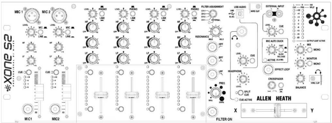
Xone:S2mixer
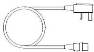
natural_image
Simple line drawing of a cable with two connectors (no text or symbols)Mains Lead
Check that the correct mains plug is fitted.
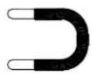
Shorting
Jumper
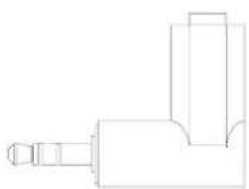
natural_image
Pure technical line drawing of a mechanical component (no text or symbols)90 degree 3.5mm jack adapter
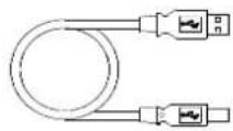
Type A-B USB Lead
To connect the Xone:S2 to your computer.
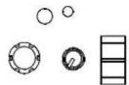
Spare knobs and buttons
Safety Sheet
Important ! Read this sheet before starting.
Retain for future reference.
Registration Card
Complete and return to Allen & Heath to register your product.
CONTENTS
Congratulations on purchasing the Allen & Heath Xone:S2 performance DJ mixer. To ensure that you get the maximum benefit from the unit please spare a few minutes familiarizing yourself with the controls and setup procedures outlined in this user guide. For further information please refer to the additional information available on our web site, or contact our technical support team.
http://www.xone.co.uk
http://www.allen-heath.com
Warranty 2
Packed Items.... 3
Panel Drawings...... 5
Introduction 6
Specifications.... 7
Block Diagram 8
Mic / Line Channel Input...... 9
Phono / Line Input Channel ..... 11
Filters Section.... 13
USB / Headphone Section 15
Headphone Cable Clips 17
External Input/AutoDuck/FX Loop 18
Master Section...... 20
Crossfader.... 22
Rear Connectors 23
Rear Connectors—Zone Out...... 28
User Link Options.... 30
Replacing Crossfader / Fader Plate. 32
PANEL DRAWINGS
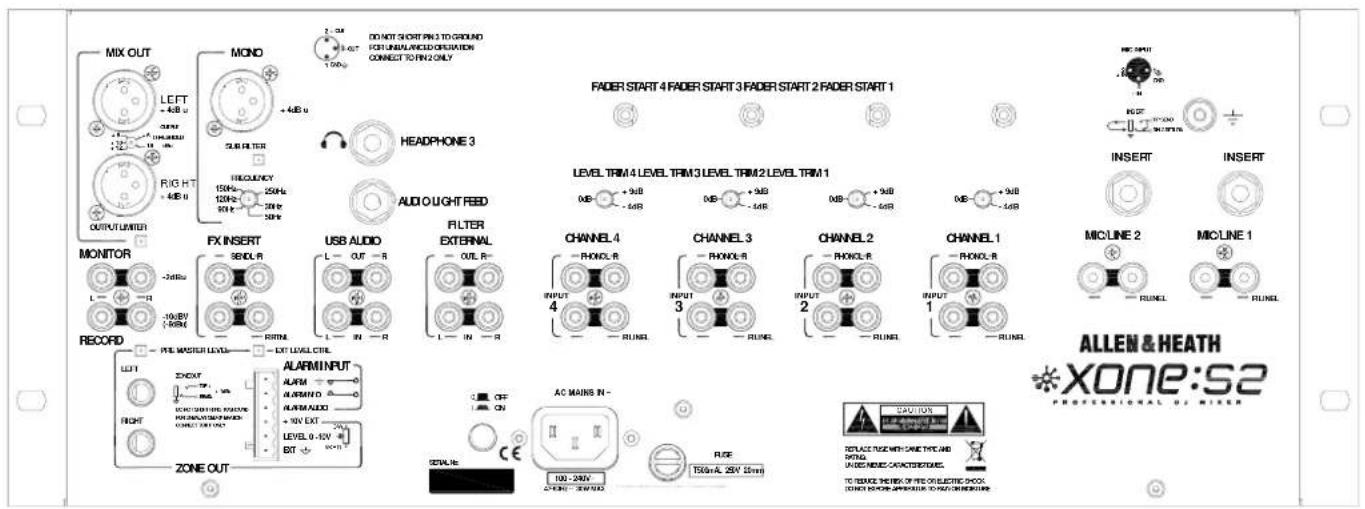
Rear Panel
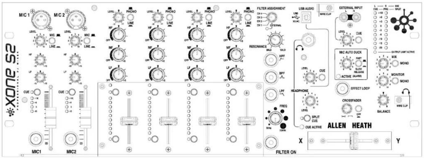
Front Panel
Fader Plates
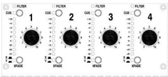
The Xone: S2 can be ordered with either rotary or linear faders. The plates are interchangeable and can be ordered separately.
Linear Fader Plate—Xone:S2-Linear
Rotary Fader Plate—Xone:S2-Rotary
INTRODUCTION TO THE XONE:S2
The Xone:S2 is a 19" rack mounted 4U analogue DJ mixer featuring four stereo dual input channels, two Mono Mic/Stereo Line channels, and is available with either 45mm linear, or rotary VCA faders.
This mixer is designed for use in clubs, wine bars, and professional mobile DJ road shows, and incorporates many features to aid the installer, protect the sound system from overload, and enhance the DJs performance. The Xone:S2 is the most feature laden 19" mixer available.
Each of the four main stereo channels is equipped with a high performance three band equalizer providing a safe +6dB of boost and total kill for complete frequency isolation.
Nine point metering on each channel allows for precise matching of signal levels, and smooth VCA faders help to ensure a perfect mix. Individual channels can be routed to either side of the high performance VCA crossfader with adjustable curve control for smooth constant level mixes or virtually instant attack suitable for scratching.
Two high quality MIC channels, each with two channel +/-15dB EQ, soft switched channel ON buttons, insert points and smooth 60mm faders are included. These channels can also accept stereo line inputs. The booth monitor is automatically ducked when a MIC channel is active, whilst an adjustable voice over control can be set to automatically duck the main music channels as soon as an announcement is made.
The Xone:S2 is also equipped with the legendary Xone Filter system. A rotary selector allows each of the four main channels to be individually routed to the filter, or the filter can be set to “External” allowing the filter to be connected to outboard equipment, or to be patched into the mixer insert point for global filtering of the main mix.
Three basic filter types can be selected, hi-pass, band-pass and low-pass. These filter types can be added together to create other filter types; e.g. hi-pass and low-pass together create a notch filter. Each filter type can be swept from 20Hz to 20 kHz by the rotary frequency control, whilst resonance can be set from “mild” to “wild”.
Uniquely on a mixer of this type, the Xone:S2 is equipped with a USB audio interface enabling easy integration of digital media. The USB interface can be used for playback and recording to/from the Xone:S2 and a computer, or can be patched into the mixer insert point and used like a hardware effects unit, (with the appropriate software).
An additional stereo input (RCA) is accessible on the front panel enabling guest DJs to patch in additional music sources without having to gain access to the rear connectors. This input is equipped with individual level and cue controls.
The master section has individual controls for the main mix and booth, each with separate mono switches. A global balance control can be used to correct source imbalance or as a panning effect.
Stereo nine point output meters display the post master level output, or the pre-fade source level when a cue is selected. In split mode the left meter displays the cue level and the right meter the master output.
A powerful headphone amp ensures more than adequate monitor level, while no less than three separate headphone sockets are provided; 3.5mm and 14 " Jack on the front panel and one 14 " Jack on the rear.
A split Cue feature allows the cue signal to be monitored in the left headphone and the main Mix in the right.
SPECIFICATIONS
Operating Levels
Input
RIAA input sensitivity 7-100mV 47K/330pF
Line Inputs -10dB to +15dB RCA
Mic Sensitivity -57 to -27dBu Balanced XLR
USB Audio In 0dBu RCA
Alarm Input 0dBu Phoenix connector
Mix Insert Return -2dBu RCA
Channel Insert Return
0dBu 1/4" TRS Jack
Filter External In 0dBu RCA
Output
Main Outputs +4dBu XLR
Monitor
-2dBu
RCA
Record
-8dBu
RCA
Zone +4dBu Balanced 1/4" TRS Jack
Mono +4dBu Impedance Balanced XLR Sub Filter
Range 30Hz—250Hz
USB Audio Out 0dBu RCA
Mix Insert Send
-2dBu RCA
Filter External Out
0dBu RCA
Channel Insert Send
0dBu 1/4" TRS Jack
Frequency response Line in to Mix out
10Hz to 20kHz +/- 0dB (-1.5dB @ 50kHz)
Distortion at 1kHz Line in at +0Vu out
Typically < -0.05% Channel In to Mix out
Main Mix noise 22Hz—22kHz unweighted
<-73 dBu (-77dB S/N)
Residual Mix noise 22Hz—22kHz unweighted
<- 90.00 dBu
Equalisation
+6dB to minus infinity (total kill)
Fader Shutoff
-86 dBr
Dimensions and Weights
The console is fitted with rubber feet for desktop operation.
| Width | Height | Depth | Weight | |
| Mixer | 482 mm (19") | 177 mm (7") | 123 mm (4.8") | 4.75 kg (10.5 lbs) |
| Packed | 600 mm (23.6") | 300 mm (11.8") | 250 mm (9.8") | 7.5 kg (16.5 lbs) |
BLOCK DIAGRAM
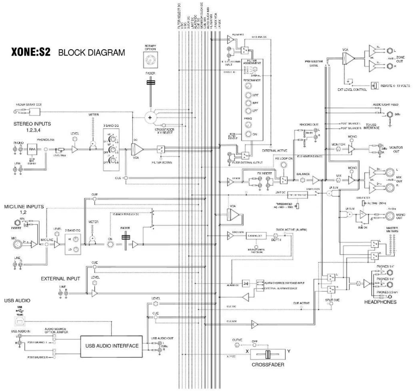
flowchart
graph TD
    subgraph Stereo INPUTS
        A["STEREO INPUTS 1.2,3,4"] --> B["PHONO"]
        B --> C["RWA"]
        C --> D["LED TEM"]
        D --> E["LEVEL"]
        E --> F["METER"]
        F --> G["3 BAND EQ"]
        G --> H["OFF"]
        H --> I["OFF"]
        I --> J["+"]
        J --> K["CROSSFADER XY SELECT"]
        K --> L["FLTR SELECT DC"]
        K --> M["X CLK"]
        K --> N["OUTDC"]
        K --> O["LINT DC"]
        K --> P["ALAWA"]
        K --> Q["MONITOR"]
        K --> R["LOCK DC"]
        K --> S["CUE MIX"]
        K --> T["ALLI DIAX"]
        K --> U["ALLI MAX"]
        K --> V["IR MIX VPA"]
        K --> W["IR MAX"]
    end

    subgraph External INPUTS
        X["MIC/LINE INPUTS 1,2"] --> Y["REFN"]
        Y --> Z["MIC/LINE"]
        Z --> AA["LEVEL"]
        AA --> AB["2 BAND EQ"]
        AB --> AC["OFF"]
        AC --> AD["ON"]
        AD --> AE["FACER"]
        AE --> AF["CUE"]
        AF --> AG["LEVEL"]
        AG --> AH["LIME R"]
        AI["EXTERNAL INPUT"] --> AJ["USB AUDIO"]
        AK["USB AUDIO INTERFACE"] --> AL["USB AUDIO OUT"]
        AM["OUTPUT"] --> AN["CUE"]
        AO["OUTPUT"] --> AP["CUE"]
        AQ["OUTPUT"] --> AR["CUE"]
    end

    subgraph Headphones
        AS["HEADPHONES 1/4'"] --> AT["PIONES 1/4'"]
        AU["HEADPHONES 1/4'"] --> AV["PIONES 3.5mm'"]
        AW["HEADPHONES"] --> AX["SPLIT CUE"]
    end

    subgraph External INPUTS
        AY["External INPUT"] --> AZ["LIME R"]
        BA["External INPUT"] --> BB["LIME R"]
        BC["External INPUT"] --> BD["LIME R"]
        BE["External INPUT"] --> BF["LIME R"]
        BG["External INPUT"] --> BH["LIME R"]
        BI["External INPUT"] --> BJ["LIME R"]
        BK["External INPUT"] --> BL["LIME R"]
        BM["External INPUT"] --> BN["LIME R"]
        BO["External INPUT"] --> BP["LIME R"]
        BQ["External INPUT"] --> BR["LIME R"]
        BS["External INPUT"] --> BT["LIME R"]
        BU["External INPUT"] --> BV["LIME R"]
        BW["External INPUT"] --> BX["LIME R"]
        BY["External INPUT"] --> BZ["LIME R"]
        CA["External INPUT"] --> CB["LIME R"]
        CC["External INPUT"] --> CD["LIME R"]
        DD["External INPUT"] --> DE["LIME R"]
        FD["External INPUT"] --> ED["LIME R"]
        EF["External INPUT"] --> GF["LIME R"]
        GH["External INPUT"] --> ID["LIME R"]
        IJ["External INPUT"] --> JK["LIME R"]
        KJL["External INPUT"] --> BKL["LIME R"]
        MLL["External INPUT"] --> BNL["LIME R"]
        MOLL["External INPUT"] --> BNL
        PNNL["External INPUT"] --> PNNL
        QNNL["External INPUT"] --> PNNL
        RNNL["External INPUT"] --> SNNL
        TNNL["External INPUT"] --> SNNL
        UNNL["External INPUT"] --> UNNL
        VNNL["External INPUT"] --> VNNL
        WNNL["External INPUT"] --> WNNL
        XNNL["External INPUT"] --> XNNL
        YNNL["External INPUT"] --> YNNL
        ZNNL["External INPUT"] --> ZNNL
        AANNL["External INPUT"] --> AANNL
        ABNNL["External INPUT"] --> ABNNL
        ACNNL["External INPUT"] --> ACNNL
        ADNNL["External INPUT"] --> ADNNL
        AENNL["External INPUT"] --> AENNL
        AFNNL["External INPUT"] --> AFNNL
        AGNNL["External INPUT"] --> AGNNL
        AHNNL["External INPUT"] --> AHNNL
        AINNL["External INPUT"] --> AINNL
        AJNNL["External INPUT"] --> AJNNL
        AKNNL["External INPUT"] --> AKNNL
        ALNNL["External INPUT"] --> ALNNL
        AMNNL["External INPUT"] --> AMNNL
        ANNNL["External INPUT"] --> ANNNL
        AONNL["External INPUT"] --> AONNL
        APNNL["External INPUT"] --> APNNL
        AQNNL["External INPUT"] --> AQNNL
        ARNNL["External INPUT"] --> ARNNL
    end

    subgraph External OUTPUT
        ASB["MIC/LINE INPUTS 1,2"] --> BZ["MIC/LINE"]
    end

    subgraph External OUTPUT
        BZM["MIC/LINE INPUTS 1,2"] --> ACZ["MIC/LINE"]
    end

    subgraph External OUTPUT
        ACZM["MIC/LINE INPUTS 1,2"] --> ADZ["MIC/LINE"]
    end

    subgraph External OUTPUT
        ADZM["MIC/LINE INPUTS 1,2"] --> AEZ["MIC/LINE"]
    end

    subgraph External OUTPUT
        AEZM["MIC/LINE INPUTS 1,2"] --> AFZ["MIC/LINE"]
    end

    subgraph External OUTPUT
        AFZM["MIC/LINE INPUTS 1,2"] --> AGZ["MIC/LINE"]
    end

    subgraph External OUTPUT
        AGZM["MIC/LINE INPUTS 1,2"] --> AHZ["MIC/LINE"]
    end

    subgraph External OUTPUT
        AHZM["MIC/LINE INPUTS 1,2"] --> AIZ["MIC/LINE"]
    end

    subgraph External OUTPUT
        AIZM["MIC/LINE INPUTS 1,2"] --> AJZ["MIC/LINE"]
    end

    subgraph External OUTPUT
        AJZM["MIC/LINE INPUTS 1,2"] --> AKZ["MIC/LINE"]
    end

    subgraph External OUTPUT
        AKZM["MIC/LINE INPUTS 1,2"] --> ALZ["MIC/LINE"]
    end

    subgraph External OUTPUT
        ALZM["MIC/LINE INPUTS 1,2"] --> AMZ["MIC/LINE"]
    end

    subgraph External OUTPUT
        AMZM["MIC/LINE INPUTS 1,2"] --> ANZ["MIC/LINE"]
    end

    subgraph External OUTPUT
        ANZM["MIC/LINE INPUTS 1,2"] --> AOZ["MIC/LINE"]
    end

    subgraph External OUTPUT
        AOZM["MIC/LINE INPUTS 1,2"] --> APZ["MIC/LINE"]
    end

    subgraph External OUTPUT
        APZM["MIC/LINE INPUTS 1,2"] --> AQ["MIC/LINE"]
    end

    subgraph External OUTPUT
        AQM["MIC/LINE INPUTS 1,2"] --> ARN["MIC/LINE"]
    end

    subgraph External OUTPUT
        ARN["MIC/LINE INPUTS 1,2"] --> ASN["MIC/LINE"]
    end

    subgraph External OUTPUT
        ASN["MIC/LINE INPUTS 1,2"] --> ATN["MIC/LINE"]
    end

    subgraph External OUTPUT
        ATN["MIC/LINE INPUTS 1,2"] --> AU["NM/MONITOR/DISC-CCD"]
    end

    subgraph External OUTPUT
        AU["NM/MONITOR/DISC-CCD"] --> AV["FACER"]
    end

    subgraph External OUTPUT
        AV["FACER"] --> AW["CUE"]
    end

    subgraph External OUTPUT
        AW["FACER"] --> AX["CUE"]

    subgraph External OUTPUT
        AX["FACER"] --> AY["CUE"]

    subgraph External OUTPUT
        AY["FACER"] --> AZ["CUE"]

    subgraph External OUTPUT
        AZ["FACER"] --> BA["CUE"]

    subgraph External OUTPUT
        BA["FACER"] --> BB["CUE"]

    subgraph External OUTPUT
        BB["FACER"] --> BC["CUE"]

    subgraph External OUTPUT
        BC["FACER"] --> BD["CUE"]

    subgraph External OUTPUT
        BD["FACER"] --> BE["CUE"]

    subgraph External OUTPUT
        BE["FACER"] --> BF["CUE"]

    subgraph External OUTPUT
        BF["FACER"] --> BG["CUE"]

    subgraph External OUTPUT
        BG["FACER"] --> BH["CUE"]

    subgraph External OUTPUT
        BH["FACER"] --> BI["CUE"]

    subgraph External OUTPUT
        BI["FACER"] --> BJ["CUE"]

    subgraph External OUTPUT
        BJ["FACER"] --> BK["CUE"]

    subgraph External OUTPUT
        BK["FACER"] --> BL["CUE"]

    subgraph External OUTPUT
        BL["FACER"] --> BM["CUE"]

    subgraph External OUTPUT
        BM["FACER"] --> BN["CUE"]

    subgraph External OUTPUT
        BN["FACER"] --> BO["CUE"]

    subgraph External OUTPUT
        BO["FACER"] --> BP["CUE"]

    subgraph External OUTPUT
        BP["FACER"] --> BQ["CUE"]

    subgraph External OUTPUT
        BQ["FACER"] --> BR["CUE"]

    subgraph External OUTPUT
        BR["FACER"] --> BS["CUE"]

    subgraph External OUTPUT
        BS["FACER"] --> BT["CUE"]

    subgraph External OUTPUT
        BT["FACER"] --> BU["CUE"]

    subgraph External OUTPUT
        BU["FACER"] --> BV["CUE"]

    subgraph External OUTPUT
        BV["FACER"] --> BW["CUE"]

    subgraph External OUTPUT
        BW["FACER"] --> BX["CUE"]

    subgraph External OUTPUT
        BX["FACER"] --> BY["CUE"]

    subgraph External OUTPUT
        BY["FACER"] --> BZ["CUE"]

    subgraph External OUTPUT
        BZ["FACER"] --> BN["CUE"]

    subgraph External OUTPUT
        BN["FACER"] --> BB["CUE"]

    subgraph External OUTPUT
        BB["FACER"] --> BC["CUE"]

    subgraph External OUTPUT
        BC["FACER"] --> BN["CUE"]

    subgraph External OUTPUT
        BN["FACER"] --> BW["CUE"]

    subgraph External OUTPUT
        BW["FACER"] --> BX["CUE"]

    subgraph External OUTPUT
        BX["FACER"] --> BY["CUE"]

    subgraph External OUTPUT
        BY["FACER"] --> BZ["CUE"]

    subgraph External OUTPUT
        BZ["FACER"] --> BN["CUE"]

    subgraph External OUTPUT
        BN["FACER"] --> BB["CUE"]

    subgraph external OUTPUTs
      X_0[XILE IN ACCUMULATED WITH OUTLEMS OF CHINA SCIENCE & TECHNOLOGY SCIENCE AND TECHNOLOGY SCIENCE AND TECHNOLOGY SCIENCE AND TECHNOLOGY SCIENCE AND TECHNOLOGY SCIENCE AND TECHNOLOGY SCIENCE AND TECHNOLOGY SCIENCE AND TECHNOLOGY SCIENCE AND TECHNOLOGY SCIENCE AND TECHNOLOGY SCIENCE AND TECHNOLOGY SCIENCE AND TECHNOLOGY SCIENCE AND TECHNOLOGY SCIENCE AND TECHNOLOGY SCIENCE AND TECHNOLOGY SCIENCE AND TECHNOLOGY SCIENCE AND TECHNOLOGY SCIENCE AND TECHNOLOGY SCIENCE AND TECHNOLOGY SCIENCE AND TECHNOLOGY SCIENCE AND TECHNOLOGY SCIENCE & TECHNOLOGY SCIENCE AND TECHNOLOGY SCIENCE AND TECHNOLOGY SCIENCE AND TECHNOLOGY SCIENCE AND TECHNOLOGY SCIENCE AND TECHNOLOGY SCIENCE AND TECHNOLOGY SCIENCE AND TECHNOLOGY SCIENCE AND TECHNOLOGY SCIENCE AND TECHNOLOGY SCIENCE AND TECHNOLOGY SCIENCE AND TECHNOLOGY SCIENCE AND TECHNOLOGY SCIENCE AND TECHNOLOGY SCIENCE AND TECHNOLOGY SCIENCE AND TECHNOLOGY SCIENCE AND TECHNOLOGY SCIENCE AND TECHNOLOGY SCIENCE AND TECHNOLOGY SCIENCE AND TECHNOUGO SCIENCE AND TECHNOUGO SCIENCE AND TECHNOUGO SCIENCE AND TECHNOUGO SCIENCE AND TECHNOUGO SCIENCE AND TECHNOUGO SCIENCE AND TECHNOUGO SCIENCE AND TECHNOUGO SCIENCE AND TECHNOUGO SCIENCE AND TECHNOUGO SCIENCE AND TECHNOUGO SCIENCE AND TECHNOUGO SCIENCE AND TECHNOUGO SCIENCE AND TECHNOUGO SCIENCE AND TECHNOUGO SCIENCE AND TECHNOUGO SCIENCE AND TECHNOUGO SCIENCE AND Technological Control & REMOTE OF 10 VOLTS |
    end

    X_0[XILE IN ACCUMULATED WITH OUTLEMS OF CHINA SCIENCE & TECHNOLOGY SCIENCE AND TECHNOLOGY SCIENCE AND TECHNOUGO SCIENCE AND TECHNOUGO SCIENCE AND TECHNOUGO SCIENCE AND TECHNOUGO SCIENCE AND TECHNOUGO SCIENCE AND TECHNOUGO SCIENCE AND TECHNOUGO SCIENCE AND TECHNOUGO SCIENCE AND TECHNOUGO SCIENCE AND TECHNOUGO SCIENCE AND TECHNOUGO SCIENCE AND TECHNOUGO SCIENCE AND Technological Control & REMOTE OF 10 VOLTS |
    X_1[XILE IN ACCUMULATED WITH OUTLEMS OF CHINA SCIENCE & TECHNOLOGY SCIENCE AND TECHNOUGO SCIENCE AND TECHNOUGO SCIENCE AND TECHNOUGO SCIENCE AND TECHNOUGO SCIENCE AND TECHNOUGO SCIENCE AND TECHNOUGO SCIENCE AND TECHNOUGO SCIENCE AND TECHNOUGO SCIENCE AND TECHNOUGO SCIENCE AND TECHNOUGO SCIENCE AND Technological Control & REMOTE OF 10 VOLTS |
    X_2[XILE IN ACCUMULATED WITH OUTLEMS OF CHINA SCIENCE & Technological Control & REMOTE OF 10 VOLTS |
    X_3[XILE IN ACCUMULATED WITH OUTLEMS OF CHINA SCIENCE & Technological Control & REMOTE OF 10 VOLTS |
    X_4[XILE IN ACCUMULATED WITH OUTLEMS OF CHINA SCIENCE & Technological Control & REMOTE OF 10 VOLTS |
    X_5[XILE IN ACCUMULATED WITH OUTLEMS OF CHINA SCIENCE & Technological Control & REMOTE OF 10 VOLTS |
    X_6[XILE IN ACCUMULATED WITH OUTLEMS OF CHINA SCIENCE & Technological Control & REMOTE OF 10 VOLTS |
    X_7[XILE IN ACCUMULATED WITH OUTLEMS OF CHINA SCIENCE & Technological Control & REMOTE OF 10 VOLTS |
    X_8[XILE IN ACCUMULATED WITH OUTLEMS OF CHINA SCIENCE & Technological Control & REMOTE OF 10 VOLTS |
    X_9[XILE IN ACCUMULATED WITH OUTLEMS OF CHINA SCIENCE & Technological Control & REMOTE OF 10 VOLTS |
    X_10[XILE IN ACCUMULATED WITH OUTLEMS OF CHINA SCIENCE & Technological Control & REMOTE OF 10 VOLTS |
    X_11[XILE IN ACCUMULATED WITH OUTLEMS OF CHINA SCIENCE & Technological Control & REMOTE OF 10 VOLTS |
    X_12[XILE IN ACCUMULATED WITH OUTLEMS OF CHINA SCIENCE & Technological Control & REMOTE OF 10 VOLTS |
    X_13[XILE IN ACCUMULATED WITH OUTLEMS OF CHINA SCIENCE & Technological Control & REMOTE OF 10 VOLTS |
    X_14[XILE IN ACCUMULATED WITH OUTLEMS OF CHINA SCIENCE & Technological Control & REMOTE OF 10 VOLTS |
    X_15[XILE IN ACCUMULATED WITH OUTLEMS OF CHINA SCIENCE & Technological Control & REMOTE OF 10 VOLTS |
    X_16[XILE IN ACCUMULATED WITH OUTLEMS OF CHINA SCIENCE & Technological Control & REMOTE OF 10 VOLTS |
    X_17[XILE IN ACCUMULATED WITH OUTLEMS OF CHINA SCIENCE & Technological Control & REMOTE OF 10 VOLTS |
    X_18[XILE IN ACCUMULATED WITH OUTLEMS OF CHINA SCIENCE & Technological Control & REMOTE OF 10 VOLTS |
    X_19[XILE IN ACCUMULATED WITH OUTLEMS OF CHINA SCIENCE & Technological Control & REMOTE OF 10 VOLTS |
    X_20[XILE IN ACCUMULATED WITH OUTLEMS OF CHINA SCIENCE & Technological Control & REMOTE OF 10 VOLTS |
    X_21[XILE IN ACCUMULATED WITH OUTLEMS OF CHINA SCIENCE & Technological Control & REMOTE OF 10 VOLTS |
    X_22[XILE IN ACCUMULATED WITH OUTLEMS OF CHINA SCIENCE & Technological Control & REMOTE OF 10 VOLTS |
    X_23[XILE IN ACCUMULATED WITH OUTLEMS OF CHINA SCIENCE & Technological Control & REMOTE OF 10 VOLTS |
    X_24[XILE IN ACCUMULATED WITH OUTLEMS OF CHINA SCIENCE & Technological Control & REMOTE OF 10 VOLTS |
    X_25[XILE IN ACCUMULATED WITH OUTLEMS OF CHINA SCIENCE & Technological Control & REMOTE OF 10 VOLTS |
    X_26[XILE IN ACCUMULATED WITH OUTLEMS OF CHINA SCIENCE & Technological Control & REMOTE OF 10 VOLTS |
    X_27[XILE IN ACCUMULATED WITH OUTLEMS OF CHINA SCIENCE & Technological Control & REMOTE OF 10 VOLTS |
    X_28[XILE IN ACCUMULATED WITH OUTLEMS OF CHINA SCIENCE & Technological Control & REMOTE OF 10 VOLTS |
    X_29[XILE IN ACCUMULATED WITH OUTLEMS OF CHINA SCIENCE & Technological Control & REMOTE OF 10 VOLTS |
    X_30[XILE IN ACCUMULATED WITH OUTLEMS OF CHINA SCIENCE & Technological Control & REMOTE OF 10 VOLTS |
    X_31[XILE IN ACCUMULATED WITH OUTLEMS OF CHINA SCIENCE & Technological Control & REMOTE OF 10 VOLTS |
    X_32[XILE IN ACCUMULATED WITH OUTLEMS OF CHINA SCIENCE & Technological Control & REMOTE OF 10 VOLTS |
    X_33[XILE IN ACCUMULATED WITH OUTLEMS OF CHINA SCIENCE & Technological Control & REMOTE OF 10 VOLTS |
    X_34[XILE IN ACCUMULATED WITH OUTLEMS OF CHINA SCIENCE & Technological Control & REMOTE OF 10 VOLTS |
    X_35[XILE IN ACCUMULATED WITH OUTLEMS OF CHINA SCIENCE & Technological Control & REMOTE OF 10 VOLTS |
    X_36[XILE IN ACCUMULATED WITH OUTLEMS OF CHINA SCIENCE & Technological Control & REMOTE OF 10 VOLTS |
    X_37[XILE IN ACCUMULATED WITH OUTLEMS OF CHINA SCIENCE & Technological Control & REMOTE OF 10 VOLTS |
    X_38[XILE IN ACCUMULATED WITH OUTLEMS OF CHINA SCIENCE & Technological Control & REMOTE OF 10 VOLTS |
    X_39[XILE IN ACCUMULATED WITH OUTLEMS OF CHINA SCIENCE & Technological Control & REMOTE OF 10 VOLTS |
    X_40[XILE IN ACCUMULATED WITH OUTLEMS OF CHINA SCIENCE & Technological Control & REMOTE OF 10 VOLTS |
    X_41[XILE IN ACCUMULATED WITH OUTLEMS OF CHINA SCIENCE & Technological Control & REMOTE OF 10 VOLTS |
    X_42[XILE IN ACCUMULATED WITH OUTLEMS OF CHINA SCIENCE & Technological Control & REMOTE OF 10 VOLTS |
    X_43[XILE IN ACCUMULATED WITH OUTLEMS OF CHINA SCIENCE & Technological Control & REMOTE OF 10 VOLTS |
    X_44[XILE IN ACCUMULATED WITH OUTLEMS OF CHINA SCIENCE & Technological Control & REMOTE OF 10 VOLTS |
    X_45[XILE IN ACCUMULATED WITH OUTLEMS OF CHINA SCIENCE & Technological Control & REMOTE OF 10 VOLTS |
    X_46[XILE IN ACCUMULATED WITH OUTLEMS OF CHINA SCIENCE & Technological Control & REMOTE OF 10 VOLTS |
    X_47[XILE IN ACCUMULATED WITH OUTLEMS OF CHINA SCIENCE & Technological Control & REMOTE OF 10 VOLTS |
    X_48[XILE IN ACCUMULATED WITH OUTLEMS OF CHINA SCIENCE & Technological Control & REMOTE OF 10 VOLTS |
    X_49[XILE IN ACCUMULATED WITH OUTLEMS OF CHINA SCIENCE & Technological Control & REMOTE OF 10 VOLTS |
    X_50[XILE IN ACCUMULATED WITH OUTLEMS OF CHINA SCIENCE & Technological Control & REMOTE OF 10 VOLTS |
MIC / LINE INPUT CHANNEL
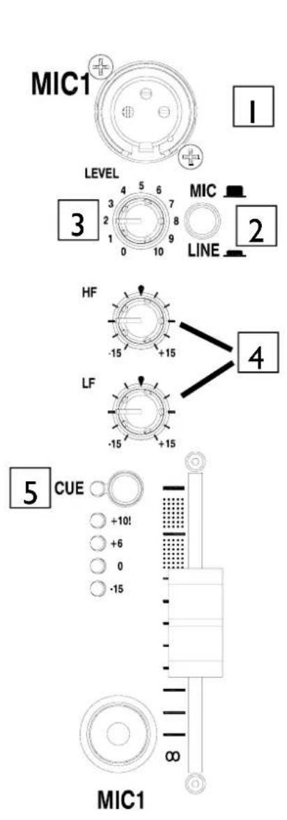
Mic Input Socket
Standard 3-Pin XLR socket wired as Pin 1 = Ground, Pin 2 = hot (+), Pin 3 = cold (-).
2 Mic / Line Select Switch
Selects either the XLR microphone input or the alternative RCA stereo line input. In the up position MIC is selected, when pressed LINE is selected.
3 Channel Level Control
This control has a range of - to +9dB for LINE inputs and a range of -57 dBU to -27dBu for MIC inputs. Use it to adjust the signal level of an audio source to give a nominal 0dB reading on the channel meter, with the peak level at or below 6dB. Turn LEVEL down if the +10 peak meter starts flashing.
4 Channel Equaliser
The Mic/Line input channel is equipped with a 2 band EQ stage providing +15dB of boost when fully clockwise and -15dB attenuation when fully anti-clockwise.
5 Cue Switch
Press the Cue switch to listen to the channel pre-fade signal in the headphones and see its level on the main meters. The LED indicator next to the switch lights when selected. The Cue LED indicator in the monitor section also lights to warn that you are monitoring the channel signal rather than the main mix. Press the switch to deselect cue.
MIC / LINE INPUT CHANNEL
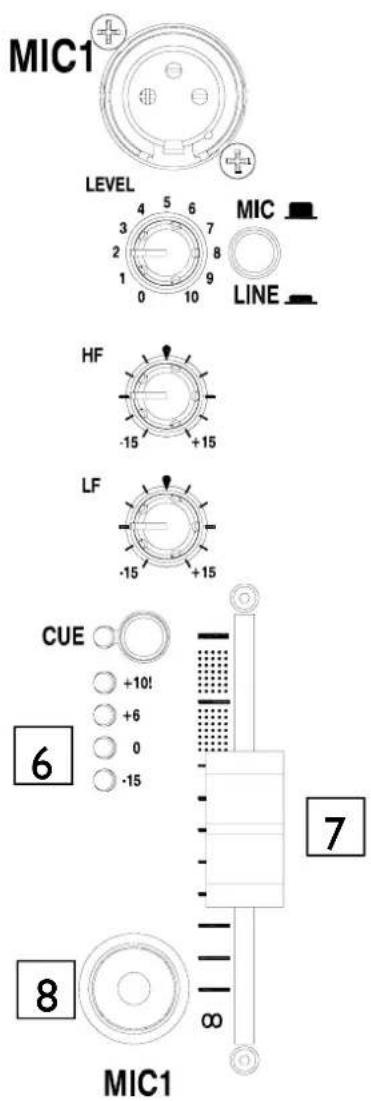

Channel Meter
Displays the channel signal level. It is post EQ and prefader. This means it is not affected by the fader position. The channel level control should be set so that the meter averages around '0' with loudest peaks no higher than '+6'. Turn down the level control if the +10 peak indicator lights.

Channel Fader
60mm smooth travel fader adjusts the channel signal level from fully off to fully on.

Mic On Switch
Press the Mic switch to send the channel audio to the mix. When selected, the LED indicator switch will illuminate yellow and the monitor output will be automatically ducked by -15dB.
The Mic On switch has two operating modes—single press or press and hold. When the switch senses a single press it will latch the channel on, when it senses a press and hold it will turn the channel off when the switch is released. This operation is ideal for making short announcements.
PHONO / LINE INPUT CHANNEL
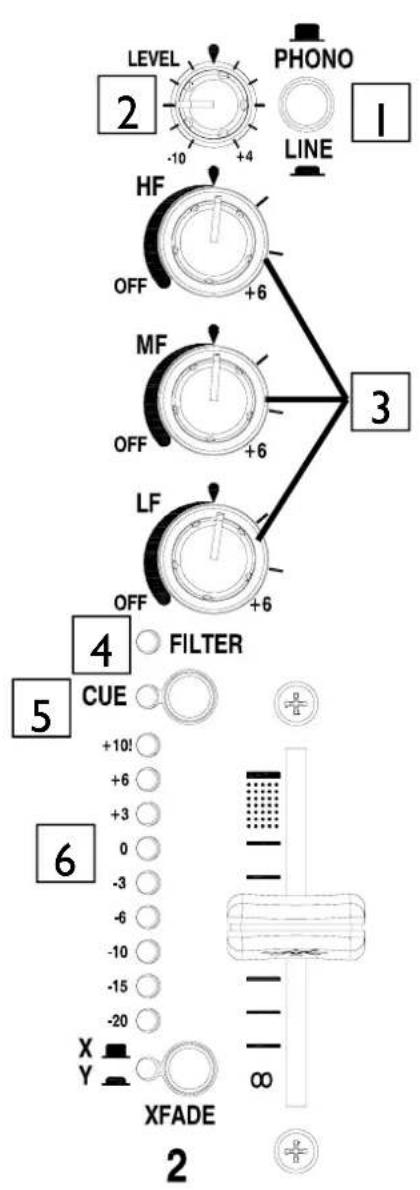
Phono / Line Select Switch
Selects either the RCA phono input or the alternative RCA stereo line input. In the up position PHONO is selected, when pressed LINE is selected.
2 Channel Level Control
This control has a range of -10 to +4dB dependant upon the channel trim. Use it to adjust the signal level of an audio source to give a nominal 0dB reading on the channel meter, with the peak level at or below 6dB. Turn LEVEL down if the +10 peak meter starts flashing.
3 Channel Equalizer / Isolator
The Xone:S2 is equipped with a very powerful 3 band EQ stage providing a controlled +6dB of boost when fully clockwise, but full isolation (cut) of each band for dramatic effect when fully anti-clockwise. Centre frequencies are set at:
$$ \begin{array}{l} \mathrm{HF} = 1 0 \mathrm{kHz} (\text { high frequency, treble }) \ \mathrm{MF} = 1. 2 \mathrm{kHz} (\text { mid frequency }) \ \mathrm{LF} = 1 2 0 \mathrm{Hz} (\text { low frequency, bass }) \ \end{array} $$
4 Filter On LED
The Filter On LED will illuminate when the filter is assigned to the selected channel.
5 Cue Switch
Press the Cue switch to listen to the channel pre-fade signal in the headphones and see its level on the main meters. The LED indicator next to the switch lights when selected. The Cue LED indicator in the monitor section also lights to warn that you are monitoring the channel signal rather than the main mix. Press the switch to deselect cue.
PHONO / LINE INPUT CHANNEL
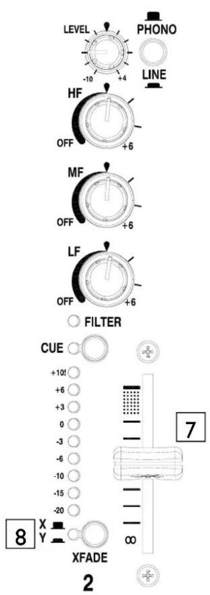
6 Channel Meter
Displays the channel signal level. It is pre-EQ and prefader, allowing the input level to be displayed even if the EQ is set to off on all bands. To view the post EQ level, press the cue switch and use the mix/monitor meters.
The channel level control should be set so that the meter averages around '0' with loudest peaks no higher than '+6'. Turn down the level control if the +10 peak indicator lights.
7 Channel Fader
A high quality, 45mm smooth travel dual-rail fader or rotary potentiometer adjusts the channel signal level from fully off to fully on.
8 XFade Switch
Used to assign the channel to either the X (left) or Y (right) side of the cross-fader. Works in conjunction with the XFADER On switch in the master section.
A bi-colour LED indicator illuminates either red (X) or yellow (Y) to show which side of the cross-fader has been selected.
FILTER SECTION
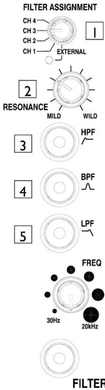
Filter Assign Selector
Selects the channel to be routed through the filter. The FILTER LED in the selected channel section will light when selected. The EXTERNAL LED will light when the selector is set to EXTERNAL.
NOTE: To prevent accidental assignment of the filter there is a delay when selecting an individual channel. For smoothest operation, use the filter on/off button before selecting another channel rather than relying on the switching delay.
2 Resonance Control
This produces the classic analogue VCF sound by feeding some of the filter output back to its input. The control ranges from 'mild' producing a very subtle effect, to 'wild' producing a dramatic phase effect with feedback just short of oscillation.
3 HPF Button
Turns on the high pass (bass cut) filter slope. The light ring around the button illuminates when selected.
4 BPF Button
Turns on the band pass (bell shaped) filter slope. The light ring around the button illuminates when selected.
5 LPF Button
Turns on the low pass (treble cut) filter slope. The light ring around the button illuminates when selected.
FILTER SECTION
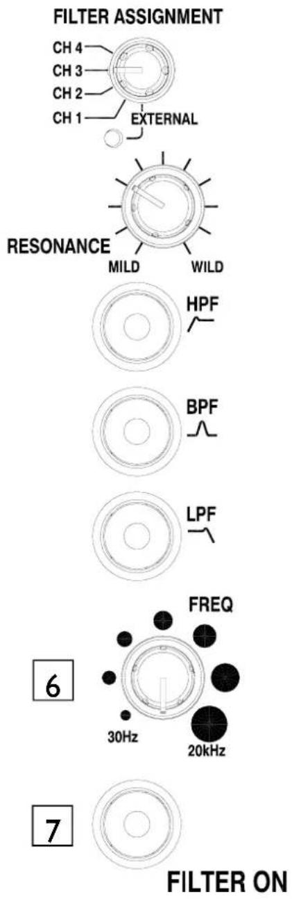
6 Frequency Sweep Control
This control sets the -3dB cut-off frequency of the filter. It ranges from very low frequency (20Hz) to very high frequency (20kHz).
NOTE: Both BPF and HPF filters are band limited to prevent them going above 10kHz.
7 Filter On Switch
Switches the filter on and off. The light ring around the button illuminates when the filter is active.
The Filter On switch has two operating modes—single press or press and hold. When the switch senses a single press it will latch the filter on, when it senses a press and hold it will turn the filter off when the switch is released.
USB AUDIO
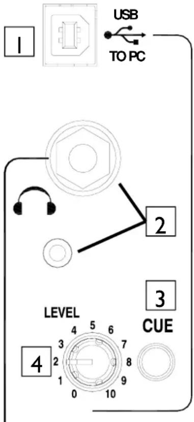
HEADPHONE

USB Connector
USB (Universal Serial Bus) VI.1 is an external peripheral interface standard for data transmission. Xone:S2 USB works at 12Mbps and provides two stereo uncompressed audio channels. It is fully compatible with USB2.
The USB connection is used to send and receive audio data between the Xone:S2 and a connected computer. Use a standard type A to B lead to connect to your computer.
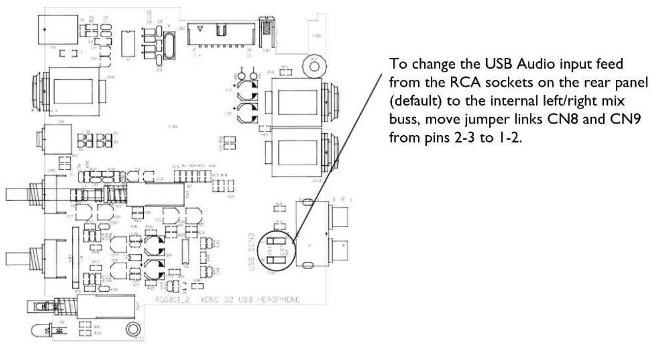
In the default configuration, the USB input to PC is from the RCA Phono connectors on the rear of the mixer. Internal option links can be set to change this to the pre-fade mix output.

Headphone Outputs
Stereo 1/4" TRS jack and 3.5mm mini-jack. Plug in good quality stereo headphones intended for DJ monitoring. Use closed-ear headphones that provide maximum acoustic isolation when cueing your sources. We recommend that you use high quality headphones rated between 30 to 100 ohms impedance. 8 ohm headphones are not recommended.

USB Cue Switch
Press the USB Cue switch to listen to the USB pre-level signal in the headphones and see its level on the main meters. The Cue LED indicator in the monitor section lights to warn that you are monitoring the USB signal rather than the main mix. Press the switch to deselect cue.

USB Level Control
Sets the level of the USB signal. The USB level control ranges from - to +6dB based on the input level and is sent to the main LR mix.
USB / HEADPHONE SECTION
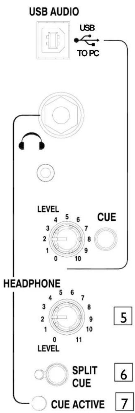
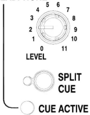
5 Headphone Level Control
Adjusts the level of the headphone signal.
Warning ! To avoid damage to your hearing do not operate the headphones or sound system at excessively high volume. Continued exposure to high volume sound can cause frequency selective or wide range hearing loss.
6 Split Cue Switch
Press the Split Cue Switch to activate split cue mode. In split cue mode the cue signal is fed to the left side of the headphones and is displayed on the left output meter. The mix remains in the right ear and its level is displayed on the right output meter.
The Split Cue LED will light when in split cue mode.
7 Cue Active LED
The Cue active LED will light when any channel or input cue button is selected.
HEADPHONE CABLE CLIPS
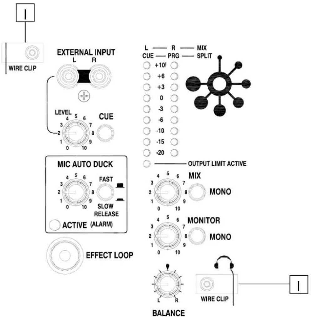

Wire Clips
Two wire clips are provided for the purpose of securing the headphone cabling away from the front panel controls of the mixer.
NOTE: A third headphone socket is available on the rear of the mixer. This connection may be used for mounting a headphone extension lead into a blank 19" panel underneath the mixer in a fixed installation.
EXTERNAL INPUT / AUTO DUCK / EFFECT LOOP
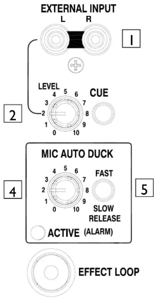
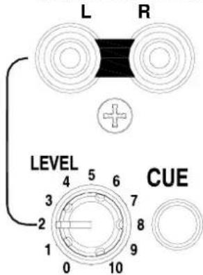
External Input Sockets
Front-panel mounted stereo RCA sockets for easy connection of external line level audio sources.
2 External Input Level Control
The external input level control ranges from - to +6dB based on the input level.
3 External Input Cue Switch
Press the external input cue switch to listen to the external input pre-level signal in the headphones and see its level on the main meters. The Cue LED indicator in the monitor section lights to warn that you are monitoring the external input signal rather than the main mix. Press the switch to deselect cue.
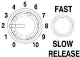
4 Mic Auto Duck Level
Selects the level of ducking on the music channels when a signal is present on the microphone inputs. Ranges from no attenuation (fully anti-clockwise) to -15dB of attenuation (fully clockwise).
5 Fast / Slow Release Switch
Changes the time taken for the main audio channels to return to their normal level after the DJ has finished speaking.
Use a fast release time for quick punchy announcements and slow release for more relaxed talk overs.
EXTERNAL INPUT / AUTO DUCK / EFFECT LOOP
EXTERNAL INPUT
6
Ducker Active LED
Lights when the main outputs are being ducked. Also lights when the external alarm input switch closure is active.
7
Effect Loop Switch
Switches in the FX insert circuit. The LED indicator around the switch lights when selected.
MIC AUTO DUCK
NOTE: If nothing is connected to the insert connectors, switching on the FX loop will break the main audio signal path.
6
7
EFFECT LOOP
MASTER SECTION

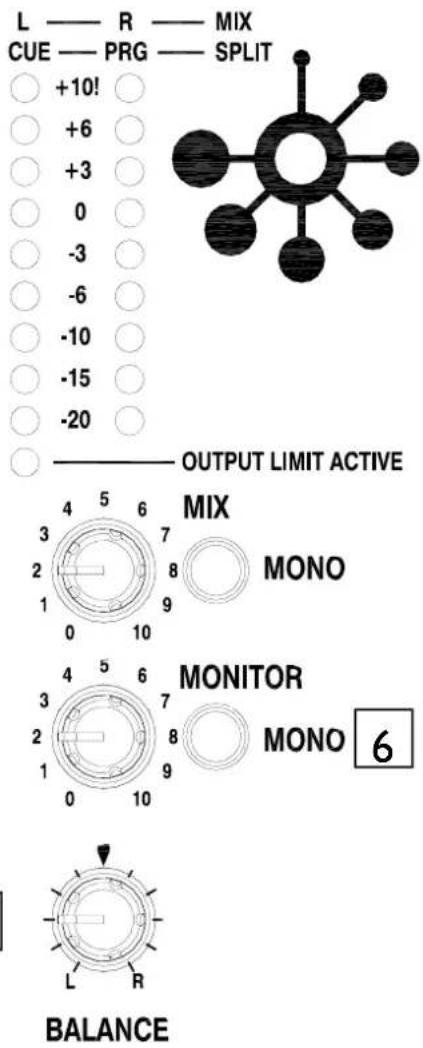
Mix / Monitor Meters
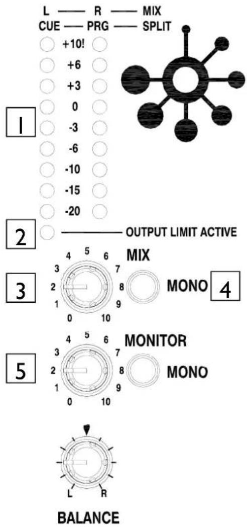
The main meters follow the selected monitor source. The default display is the post master level, which is overridden with an input channel level if the channel cue switch is selected.
In split cue mode, the left master meter will display the cued channel signal level and the right master meter will display the mix level. The cued mix audio is pre level to prevent mismatch due to the position of the master level control.
The mixer should be operated with these meters averaging around '0' with loudest peaks no higher than '+6'.

Output Limit Active LED
If the output limiter has been engaged this LED will illuminate to indicate that the threshold has been exceeded and the limiter is active. The limiter is POST the Master Level control.

Mix Master Level Control
A rotary master control adjusts the level of the main mix XLR outputs feeding the house sound system. This does not affect the monitor output or the meter reading.

Mix Mono Switch
Sums the left and right signal levels to produce a mono mix from both outputs.

Monitor Master Level Control
Adjusts the level of the signal to the stereo monitor RCA output. This does not affect the headphones. The monitor output could be used for a booth monitor, recording or an additional zone feed.
MASTER SECTION
6
Monitor Mono Switch
Sums the left and right signal levels to produce a mono mix from both outputs.
7
Balance Control
Use to compensate for poor signal balance between left and right or as a panning effect. The balance control is disabled if the outputs are set to mono.
CROSSFADER
CROSSFADER
ALLEN & HEATH
X
natural_image
Pure electrical circuit lines without any symbolsY
|
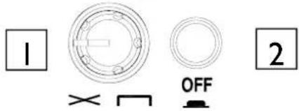
Crossfader Curve Control
This control adjusts the crossfader curve between dipped response, ideal for seamless beat mixing, and fast-attack, suitable for scratch or cut mixing.
2
Crossfader On Switch
In its normal (out) position the crossfader is active. Push the switch to turn the crossfader off—the channel LED indication will also be switched off.
3
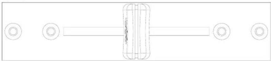
Crossfader
This lets you fade between signals routed to either side, typically to fade smoothly into a new music track or to creatively layer sounds when scratch or cut mixing.
The crossfader is a VCA controller which affects the level of signals routed via the filters. Make sure the toggle switches on the channels you wish to fade are set to X or Y as appropriate.
Please contact your Allen and Heath approved service centre for crossfader service or replacement.
REAR CONNECTORS
Mix Output
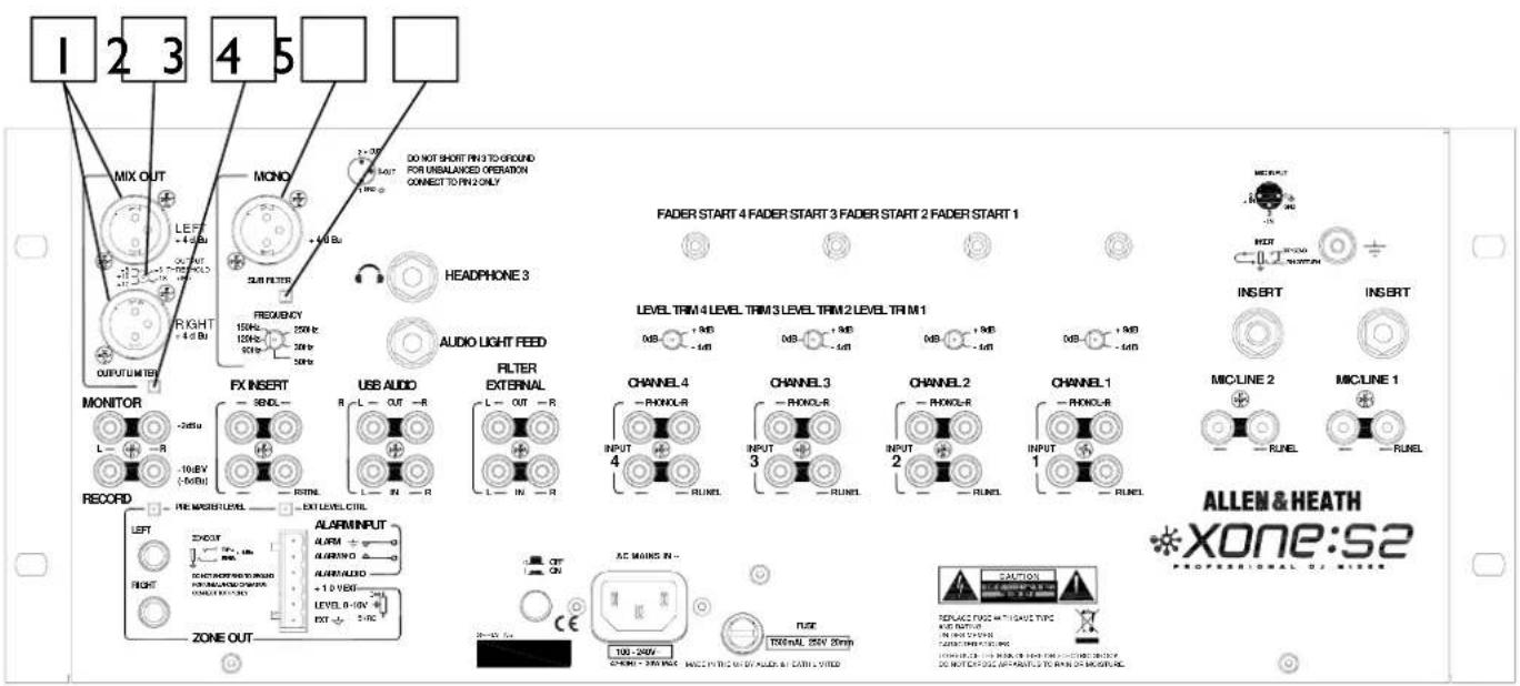
Balanced XLR. This is the main output that feeds the house PA system. Plug into the house processor/amplifier system using balanced cables. Use balanced cables and equipment. When the main meter LEDs are at "0dB" the output will nominally be at +4dBu. Do not unbalance this output by shorting one phase to ground—for unbalanced operation use pin 2 only.
2 Output Threshold Selector
Sets the output threshold level - adjustable from +6 to +18 dBu. This control is a recessed preset pot—use a thin flat blade screwdriver to adjust. Turning the pot clockwise increases the sensitivity of the limiter and reduces the maximum output level.
3 Output Limiter Switch
Using a thin screwdriver, pressing this recessed switch turns the output limiter on.
4 Mono Output
Impedance balanced XLR nominal +4dBu. The mono output can also be configured to be a sub bass output. This output follows the master level control.
5 Sub Filter Switch
Pressing this recessed switch engages a 12dB/Oct low pass filter making this output ideal as a feed for a sub bass system.
REAR CONNECTORS
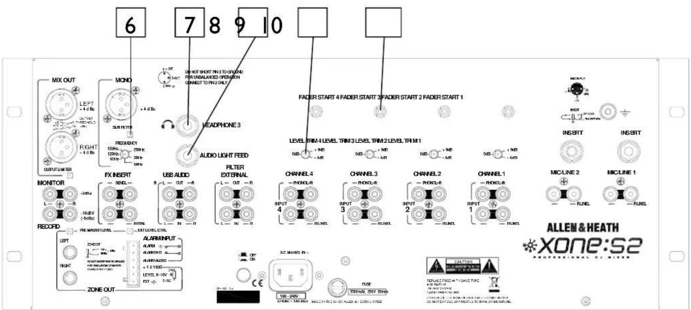
6
Frequency Cut Off Control
This sets the crossover point of the low pass filter allowing tuning of the sub bass system. The (-3dB) cut off point can be set between 30Hz and 250Hz. A graduated scale shows the approximate cut off point.
7
Headphone 3
Third headphone socket, stereo I/4" TRS jack.
8
Sound To Light
A high impedance, ground isolated mono output designed to provide an audio feed for lighting systems.
9
Channel Level Trim
This recessed control trims the channel pre-amplifier gain level to prevent overload of the PA, or to adjust to special input levels. This control works in conjunction with the front panel level control.
For instance with the trim fully anti-clockwise (-4) and the level fully clockwise (+4) the maximum channel gain will be 0dB (unity).
10
Channel Fader Start
3.5mm TRS jack follows the convention of Start—tip pulsed high and Stop—sleeve pulsed high, as used in products such as the Pioneer CDJ series.
REAR CONNECTORS
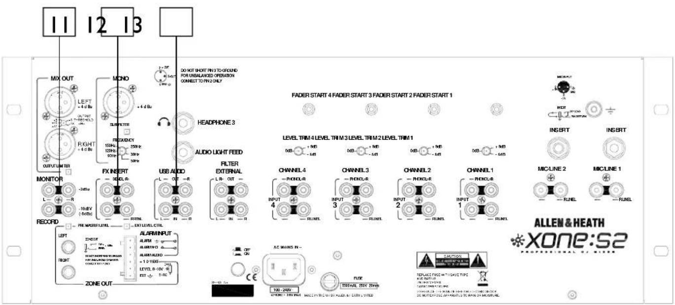
||
Monitor Output
RCA phono (-2dBu nominal). Provides a line level stereo feed to the DJ local monitor amplifier system. It is not affected by the master fader or cue system.
12
FX Insert Point
RCA phono. Provides for insertion of effects into the main out audio path. Selected using the FX Loop On switch.
NOTE: If nothing is connected to the insert, selecting the FX Loop on will break the main signal path. Always fit the supplied shorting jumpers if the insert isn't being used—the insert send is always active.
13
USB Audio I/O
RCA phono. Allows external connection to USB interface. Internal link option sets the USB to internal post balance pre level mix out if required. The default setting is for external input allowing the USB interface to be connected to the insert point and used as an effects unit with suitable software (such as Ableton Live). To record a mix using the USB In, connect to either the Record Out socket or the FX Send.
The USB interface is compatible with Windows™ 98/98SE, ME, WIN2000 and XP, MAC OS9.1, OSX (10.0) or later (but not Japanese OS 10.1).
For lowest latency with Windows, an ASIO driver is recommended such as ASIO4ALL by Michael Tippach — www.asio4all.com
REAR CONNECTORS
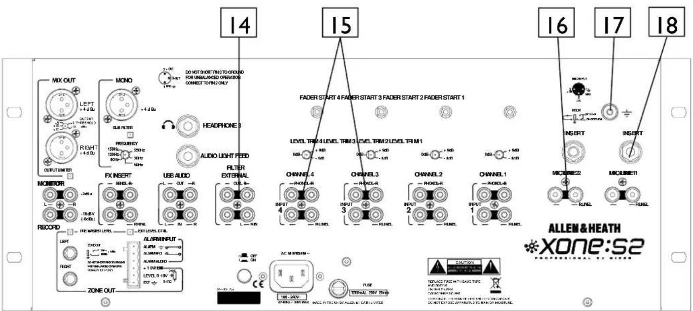

Filter External I/O
RCA Phono. Allows external connection to the filter circuitry. External source selected using Filter Assignment Selector. To use the filter as a global effect, patch the external filter sockets into the FX Insert points (Send to Filter In, Return to Filter Out).

CH I-4 Phono Input
RCA phono 7–100 mV 47k impedance 380 pF. Plug in turntables with magnetic cartridges requiring RIAA equalisation. For non-RIAA turntables plug into the LINE input instead. Do not plug in line level sources to the phono inputs as these will overload the preamp and cause severe high level distortion.

Mic / Line Channel Line Input
Stereo RCA Phono input for line source on Mic / Line channels. Connect stereo line level music sources such as CD, MD, DAT, drum machines, keyboards or other instruments. Do not connect turntables which require RIAA equalisation.

Chassis Earth Terminal
A screw terminal is provided for connecting the earth straps from turntables. This connection earths the metal parts of the turntable to reduce hum, buzz or similar audible noise getting into the system.

Mic Channel Insert Point
An insert point is provided on the Mic Input Channels wired as Tip (send) and Ring (return) on a 1/4" TRS jack.
REAR CONNECTORS
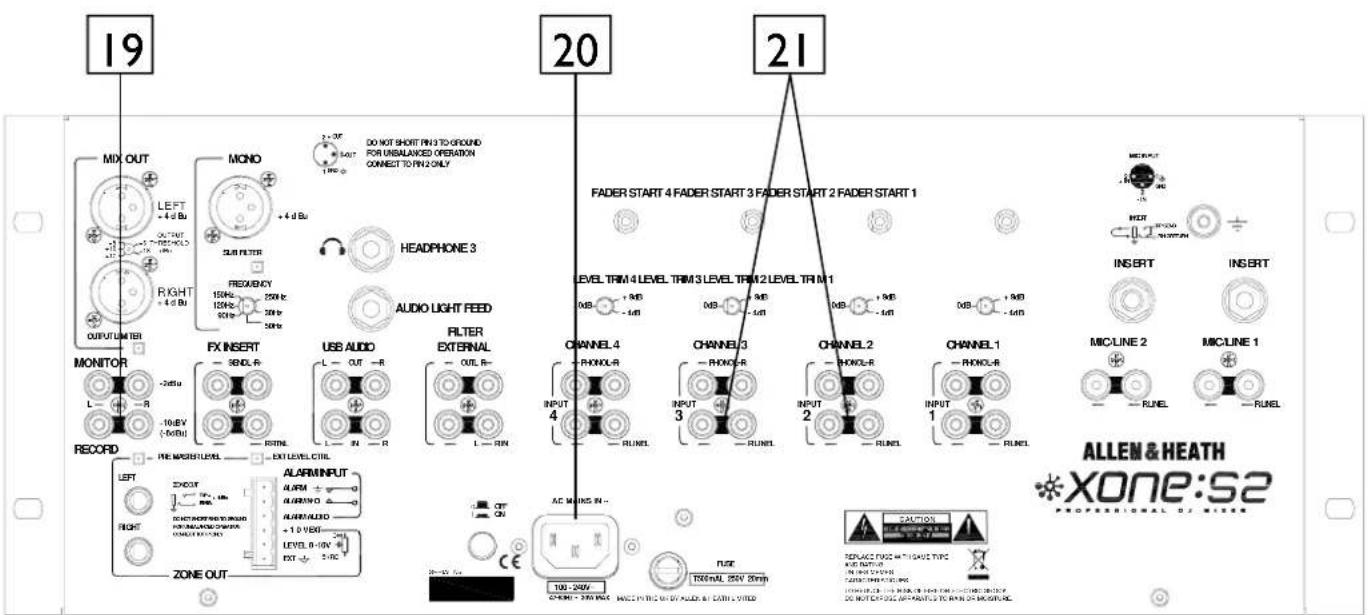
19
Record Output
RCA Phono, nominal -10dBv (-8dBu). Pre-level mix output for connection to external recording devices.
20
AC Mains Input
IEC cable with moulded mains plug suitable for your local supply.
Important: Read the SAFETY INSTRUCTIONS sheet included with the Xone:S2 and printed on the rear panel.
Check that the correct mains lead with moulded plug has been supplied with your console. The power supply accepts mains voltages within the range 100-240V without changing any fuses or settings. Ensure that the IEC mains plug is pressed fully into the rear panel socket before switching on.
Note: It is standard practice to turn connected power amplifiers down or off before switching the console on or off. This prevents any potential damage to speaker systems due to switch-on transients.
21
CH I-4 Line Input
RCA phono. Connect stereo line level music sources such as CD, MD, DAT, drum machines, keyboards or other instruments. Do not connect turntables which require RIAA equalisation. Alternatively, you can connect to jack sources using a cable with RCA to jack adapters. Avoid using low grade cables such as those often supplied with domestic equipment as these can quickly prove unreliable in use.
REAR CONNECTORS - ZONE OUT
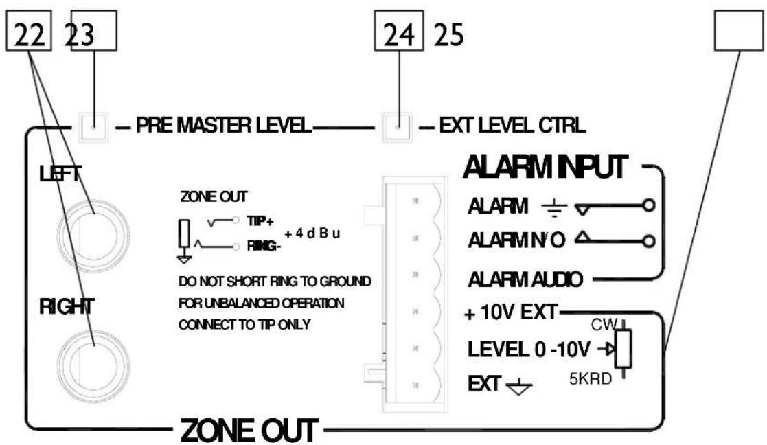
22 Zone Output
Balanced TRS Jack outputs for separate zone—nominal +4dBu. This output is ideal for feeding a separate room or bar area.
Do not unbalance this output by shorting one phase to ground. For unbalanced operation connect to Tip only.
23 Zone Pre Master Level Switch
Set this switch to source the zone output Pre Master level so that the level is not affected by the Master level control.
24 Zone External Level Control Switch
Set this switch to engage the external level control circuitry. If external control is not connected this will mute the zone output.
25 External Level Control
The zone output can be easily remote controlled with a simple three-wire interface to a suitable potentiometer. Almost any potentiometer will work but for the best control we
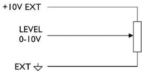
recommend a 5kΩ Reverse Log Law. The external control will also interface with any controller that follows the standard 0-10V convention such as AMX ^TM or Crestron ^TM controllers.
REAR CONNECTORS - ZONE OUT
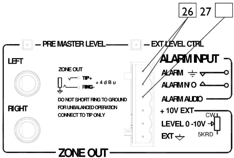
26 Alarm Override Switch Input
To interface to safety alarm systems, shorting these two connections together will mute the four main music channels but leave the Mic channels open. The Duck LED on the front panel also illuminates to show that the alarm has been activated.
27 External Alarm Audio
High impedance input for interfacing to a pre-recorded safety message (0dBu nominal).
NOTE: Poor routing of this input could cause noise or hum.
USER LINK OPTIONS
CAUTION: The following service instructions are for use by qualified personnel only.
To reduce the risk of electric shock do not perform any servicing other than that described in the operating instructions unless you are qualified to do so. Refer all servicing to qualified service personnel.
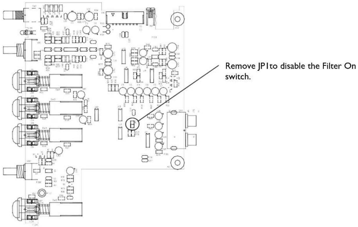
Input Channel PCB
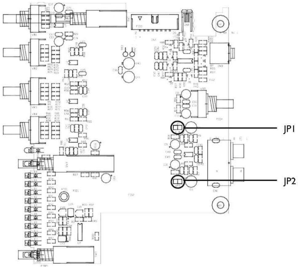
Remove jumper links JPI and JP2 to convert the RIAA stage to line level.
USER LINK OPTIONS
Filter PCB
Headphone PCB
REPLACING THE CROSSFADER / FACE PLATE
natural_image
Technical line drawing of a server rack with multiple ports and connectors (no text or labels)Replacing the Crossfader
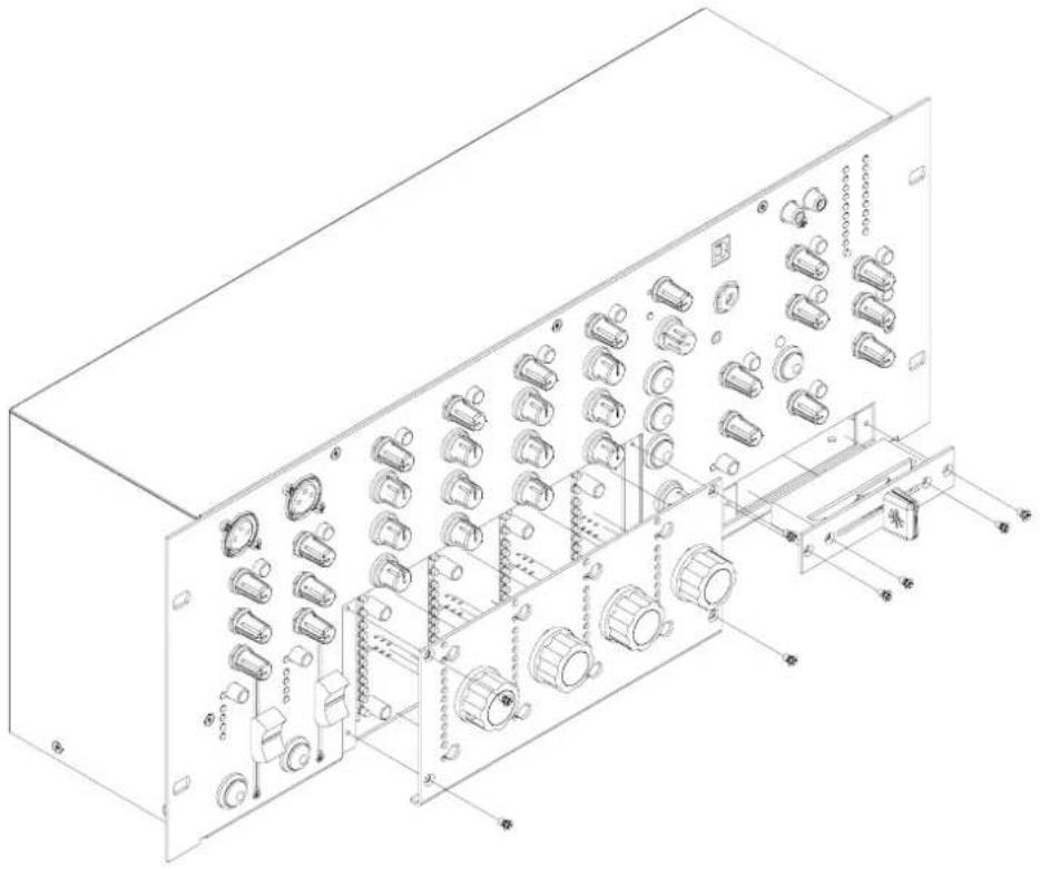
Use a medium size cross-point screwdriver to undo and remove the two outer screws on the crossfader plate. Do not remove the inner screws. Carefully pull the crossfader assembly away from the front panel. Unplug the cable from the old crossfader and plug in the new assembly. Check that the connector is correctly aligned and pushed on. Replace the assembly making sure the cable faces the left side of the console. Refit the screws and test operation.
Standard Alpha Crossfader Part Number—003-724
Penny and Giles Crossfader Option Part number—003-726 JIT
Replacing the Fader Plate
To convert the Xone:S2 from linear faders to rotary or from rotary to linear, undo the four cross-point screws and carefully pull fader plate away from the front panel. Gently pull the wire harness of the fader PCB (be very careful not to pull the other end of the harness off the slave PCB).
Replacement is the reversal.
Rotary Fader Plate - Xone:S2—Rotary
Linear Fader Plate - Xone:S2—Linear
- Limited One Year Warranty
- Conditions Of Warranty
- PACKED ITEMS
- CONTENTS
- PANEL DRAWINGS
- INTRODUCTION TO THE XONE:S2
- SPECIFICATIONS
- Operating Levels
- Input
- Output
- Dimensions and Weights
- BLOCK DIAGRAM
- MIC / LINE INPUT CHANNEL
- Mic Input Socket
- Mic / Line Select Switch
- Channel Level Control
- Channel Equaliser
- Cue Switch
- Channel Meter
- Channel Fader
- Mic On Switch
- PHONO / LINE INPUT CHANNEL
- Phono / Line Select Switch
- Channel Level Control
- Channel Equalizer / Isolator
- Filter On LED
- Channel Meter
- Channel Fader
- XFade Switch
- FILTER SECTION
- Filter Assign Selector
- Resonance Control
- HPF Button
- BPF Button
- LPF Button
- Frequency Sweep Control
- Filter On Switch
- USB Connector
- Headphone Outputs
- USB Cue Switch
- USB Level Control
- USB / HEADPHONE SECTION
- Headphone Level Control
- Split Cue Switch
- Cue Active LED
- HEADPHONE CABLE CLIPS
- Wire Clips
- EXTERNAL INPUT / AUTO DUCK / EFFECT LOOP
- External Input Sockets
- External Input Level Control
- External Input Cue Switch
- Mic Auto Duck Level
- Fast / Slow Release Switch
- Ducker Active LED
- Effect Loop Switch
- MASTER SECTION
- Mix / Monitor Meters
- Output Limit Active LED
- Mix Master Level Control
- Mix Mono Switch
- Monitor Master Level Control
- Monitor Mono Switch
- Balance Control
- CROSSFADER
- Crossfader Curve Control
- Crossfader On Switch
- REAR CONNECTORS
- Mix Output
- Output Threshold Selector
- Output Limiter Switch
- Mono Output
- Sub Filter Switch
- 6
- Frequency Cut Off Control
- 7
- Headphone 3
- 8
- Sound To Light
- 9
- Channel Level Trim
- 10
- Channel Fader Start
- ||
- Monitor Output
- 12
- FX Insert Point
- 13
- USB Audio I/O
- Filter External I/O
- CH I-4 Phono Input
- Mic / Line Channel Line Input
- Chassis Earth Terminal
- Mic Channel Insert Point
- 19
- Record Output
- 20
- AC Mains Input
- Important: Read the SAFETY INSTRUCTIONS sheet included with the Xone:S2 and printed on the rear panel.
- 21
- CH I-4 Line Input
- REAR CONNECTORS - ZONE OUT
- Zone Output
- Zone Pre Master Level Switch
- Zone External Level Control Switch
- External Level Control
- Alarm Override Switch Input
- External Alarm Audio
- USER LINK OPTIONS
- REPLACING THE CROSSFADER / FACE PLATE
- Replacing the Crossfader
- Replacing the Fader Plate
Brand : ALLEN & HEATH
Model : XONE:S2L
Category : Blender