
Model 12 - Media player TASCAM - Free user manual and instructions
Find the device manual for free Model 12 TASCAM in PDF.


| Product type | Digital mixing console / multitrack recorder |
| Brand | Tascam |
| Model | Model 12 |
| Dimensions (W x D x H) | 44.0 x 30.0 x 9.0 cm |
| Weight | 2.5 kg |
| Power supply | 12 V DC power adapter (included) |
| Power consumption | 12 W |
| Number of input channels | 12 (8 mono + 2 stereo) |
| Multitrack recording | Up to 12 simultaneous tracks on SD card |
| Supported audio formats | WAV, MP3 |
| Built-in effects | Reverb, delay, chorus, etc. |
| Connectivity | USB, Bluetooth (reception), headphone output, main XLR outputs |
| Display | Backlit LCD screen |
| Storage media | SD/SDHC card up to 32 GB |
| Care and cleaning | Use a dry, soft cloth. Avoid solvents. |
| Safety | Do not expose to moisture or shocks. Disconnect before cleaning. |
| Spare parts and repairability | Contact Tascam customer service or an authorized center. |
| Warranty | 2 years (according to applicable legislation) |
Frequently Asked Questions - Model 12 TASCAM
User questions about Model 12 TASCAM
0 question about this device. Answer the ones you know or ask your own.
Ask a new question about this device
Download the instructions for your Media player in PDF format for free! Find your manual Model 12 - TASCAM and take your electronic device back in hand. On this page are published all the documents necessary for the use of your device. Model 12 by TASCAM.
USER MANUAL Model 12 TASCAM
●TASCAM is a registered trademark of TEAC Corporation.
- SDXC Logo is a trademark of SD-3C, LLC.

- The Bluetooth® word mark and logo are the property of Bluetooth SIG, Inc. and are used by TEAC Corporation with permission.
●Microsoft, Windows and Windows Media are either registered trademarks or trademarks of Microsoft Corporation in the United States and/or other countries.
●Apple, Mac, macOS, iPad, iPadOS and iTunes are trademarks of Apple Inc. in the United States and other countries.
●Lightning is a trademark of Apple Inc.
●App Store is a service mark of Apple Inc. - IOS is a trademark or registered trademark of Cisco in the U.S. and other countries and is used under license.
●ASIO is a trademark of Steinberg Media Technologies GmbH.
ASIO
COMPATIBLE
ASIO is a registered trademark of Steinberg Media Technologies GmbH
●Other company names, product names and logos in this document are the trademarks or registered trademarks of their respective owners.
Information is given about products in this manual only for the purpose of example and does not indicate any guarantees against infringements of third-party intellectual property rights and other rights related to them. TEAC Corporation will bear no responsibility for infringements on third-party intellectual property rights or their occurrence because of the use of these products.
Properties copyrighted by third parties cannot be used for any purpose other than personal enjoyment and the like without the permission of the right holders recognized by copyright law. Always use this equipment properly. TEAC Corporation will bear no responsibility for rights infringements committed by users of this product.
IMPORTANT SAFETY INSTRUCTIONS
WARNING: TO PREVENT FIRE OR SHOCK HAZARD, DO NOT EXPOSE THIS APPLIANCE TO RAIN OR MOISTURE.
For U.S.A.
Supplier's Declaration of Conformity
Model Number: Model 12
Trade Name: TASCAM
Responsible party: TEAC AMERICA, INC.
Address: 10410 Pioneer Blvd., Unit #1, Santa Fe Springs, California 90670, U.S.A

Telephone number: 1-323-726-0303
This device complies with Part 15 of the FCC Rules. Operation is subject to the following two conditions: (1) this device may not cause harmful interference, and (2) this device must accept any interference received, including interference that may cause undesired operation.
INFORMATION TO THE USER
This equipment has been tested and found to comply with the limits for a Class B digital device, pursuant to Part 15 of the FCC Rules. These limits are designed to provide reasonable protection against harmful interference in a residential installation. This equipment generates, uses, and can radiate radio frequency energy and, if not installed and used in accordance with the instructions, may cause harmful interference to radio communications. However, there is no guarantee that interference will not occur in a particular installation. If this equipment does cause harmful interference to radio or television reception, which can be determined by turning the equipment off and on, the user is encouraged to try to correct the interference by one or more of the following measures.
a) Reorient or relocate the receiving antenna.
b) Increase the separation between the equipment and receiver.
c) Connect the equipment into an outlet on a circuit different from that to which the receiver is connected.
d) Consult the dealer or an experienced radio/TV technician for help.
CAUTION
Changes or modifications to this equipment not expressly approved by TEAC CORPORATION for compliance could void the user's authority to operate this equipment.
For Canada
THIS CLASS B DIGITAL APPARATUS COMPLIES WITH CANADIAN ICES-003.
CET APPAREIL NUMERIQUE DE LA CLASSE B EST CONFORME A LA NORME NMB-003 DU CANADA.

This product complies with the European Directives request and the other Commission Regulations.

This product complies with applicable UK regulations.
- Read these instructions.
- Keep these instructions.
- Heed all warnings.
- Follow all instructions.
- Do not use this apparatus near water.
- Clean only with dry cloth.
- Do not block any ventilation openings. Install in accordance with the manufacturer's instructions.
- Do not install near any heat sources such as radiators, heat registers, stoves, or other apparatus (including amplifiers) that produce heat.
- Do not defeat the safety purpose of the polarized or grounding-type plug. A polarized plug has two blades with one wider than the other. A grounding type plug has two blades and a third grounding prong. The wide blade or the third prong are provided for your safety. If the provided plug does not fit into your outlet, consult an electrician for replacement of the obsolete outlet.
- Protect the power cord from being walked on or pinched particularly at plugs, convenience receptacles, and the point where they exit from the apparatus.
- Only use attachments/accessories specified by the manufacturer.
- Use only with the cart, stand, tripod, bracket, or table specified by the manufacturer, or sold with the apparatus. When a cart is used, use caution when moving the cart/ apparatus combination to avoid injury from tip-over.

-
Unplug this apparatus during lightning storms or when unused for long periods of time.
-
Refer all servicing to qualified service personnel. Servicing is required when the apparatus has been damaged in any way, such as power-supply cord or plug is damaged, liquid has been spilled or objects have fallen into the apparatus, the apparatus has been exposed to rain or moisture, does not operate normally, or has been dropped.
-
The apparatus draws nominal non-operating power from the AC outlet with its POWER or STANDBY/ON switch not in the ON position.
- The mains plug is used as the disconnect device, the disconnect device shall remain readily operable.
- Caution should be taken when using earphones or headphones with the product because excessive sound pressure (volume) from earphones or headphones can cause hearing loss.
- If you are experiencing problems with this product, contact TEAC for a service referral. Do not use the product until it has been repaired.
WARNING
- To prevent possible hearing damage, do not listen at high volume levels for long periods.

CAUTION
- Do not expose this apparatus to drips or splashes.
- Do not place any objects filled with liquids, such as vases, on the apparatus.
- Do not install this apparatus in a confined space such as a book case or similar unit.
- The apparatus should be located close enough to the AC outlet so that you can easily grasp the power cord plug at any time.
- If the product uses batteries (including a battery pack or installed batteries), they should not be exposed to sunshine, fire or excessive heat.
- CAUTION for products that use replaceable lithium batteries: there is danger of explosion if a battery is replaced with an incorrect type of battery. Replace only with the same or equivalent type.
- Installed battery subjected to extremely low air pressure may result in an explosion or the leakage of flammable liquid or gas.
CAUTION
- DO NOT REMOVE THE EXTERNAL CASES OR CABINETS TO EXPOSE THE ELECTRONICS. NO USER SERVICEABLE PARTS ARE INSIDE.
- IF YOU ARE EXPERIENCING PROBLEMS WITH THIS PRODUCT, CONTACT THE STORE WHERE YOU PURCHASED THE UNIT FOR A SERVICE REFERRAL. DO NOT USE THE PRODUCT UNTIL IT HAS BEEN REPAIRED.
- USE OF CONTROLS OR ADJUSTMENTS OR PERFORMANCE OF PROCEDURES OTHER THAN THOSE SPECIFIED HEREIN MAY RESULT IN HAZARDOUS RADIATION EXPOSURE.
For European Customers
Disposal of electrical and electronic equipment and batteries and/or accumulators
(a) All electrical/electronic equipment and waste batteries/accumulators should be disposed of separately from the municipal waste stream via collection facilities designated by the government or local authorities.
(b) By disposing of electrical/electronic equipment and waste batteries/accumulators correctly, you will help save valuable resources and prevent any potential negative effects on human health and the environment.
(c) Improper disposal of waste electrical/electronic equipment and batteries/accumulators can have serious effects on the environment and human health because of the presence of hazardous substances in the equipment.
(d) The Waste Electrical and Electronic Equipment (WEEE) symbols, which show wheeled bins that have been crossed out, indicate that electrical/electronic equipment and batteries/accumulators must be collected and disposed of separately from household waste.
If a battery or accumulator contains more than the specified values of lead (Pb), mercury (Hg), and/or cadmium (Cd) as defined in the Battery Directive (2006/66/EC, 2013/56/EU), then the chemical symbols for those elements will be indicated beneath the WEEE symbol.
(e) Return and collection systems are available to end users. For more detailed information about the disposal of old electrical/electronic equipment and waste batteries/accumulators, please contact your city office, waste disposal service or the shop where you purchased the equipment.
For China
Compliance of radio transmitter and interference
This product has the function of broadband transmitter using 2.4GHz Band.
Use frequency range: 2400 MHz - 2480 MHz
Maximum output power: Bluetooth ^® Class 2 (less than 2.5 mW) Please use only in the country where you purchased the product. Depending on the country, restrictions on the use of Bluetooth wireless technology might exist.
Model for USA
Supplier's Declaration of Conformity
Responsible party: TEAC AMERICA, INC.
Address: 10410 Pioneer Blvd., Unit #1, Santa Fe Springs, California 90670, U.S.A
Telephone number: 1-323-726-0303

This device complies with Part.15 of FCC Rules. Operation is subject to the following two conditions: (1) this device may not cause harmful interference, and (2) this device must accept any interference received, including interference that may cause undesired operation.
Labeling of authorization
FCC ID: XEG-MODEL12
Model for Canada
Compliance of radio transmitter
This device complies with Industry Canada's licence-exempt RSSs.
Operation is subject to the following two conditions:
1) This device may not cause interference
2) This device must accept any interference, including interference that may cause undesired operation of the device.
Labeling of authorization
IC: 1559C-MODEL12
Model for EEA (European Economic Area)

Hereby, TEAC Corporation declares that the radio equipment type is in compliance with Directive 2014/53/EU., and the other Directives, and Commission Regulations.
The full text of the EU declaration of conformity is available at the following internet address: Please contact us by e-mail.
https://tascam.eu/en/contact.html
EU Importer: TEAC Europe GmbH
Radiation Exposure requirements
This equipment meets the regulation, which is recognized internationally, for the case of human exposure to radio waves generated by the transmitter.
Statement of compliance
Model for USA
This equipment complies with FCC radiation exposure limits set forth for an uncontrolled environment and meets the FCC radio frequency Exposure Guidelines.
Model for Canada
This equipment complies with IC RSS-102 radiation exposure limits set forth for an uncontrolled environment.
Model for USA/Canada
This Class B digital apparatus complies with Canadian ICES-003. This equipment complies with FCC/IC radiation exposure limits set forth for an uncontrolled environment and meets the FCC radio frequency (RF) Exposure Guidelines and RSS-102 of the IC radio frequency (RF) Exposure rules. This equipment has very low levels of RF energy that it deemed to comply without maximum permissive exposure evaluation (MPE). But it is desirable that it should be installed and operated keeping the radiator at least 20 cm or more away from person's body (excluding extremities: hands, wrists, feet and ankles).
Model for EEA (European Economic Area)
This equipment complies with EN.62311; Assessment of electronic and electrical equipment related to human exposure restrictions for electromagnetic fields; the harmonised standard of DIRECTIVE 2014/53/EU.
INSTRUCTIONS DE SÉCURITÉ IMPORTANTES
AVERTISSEMENT : POUR PRÉVENIR LES RISQUES D'INCENDIE ET D'ÉLECTROCUTION, N'EXPOSEZ PAS CET APPAREIL À LA PLUIE NI À L'HUMIDITÉ.
Pour le Canada
CET APPAREIL NUMÉRIQUE DE LA CLASSE B EST CONFORME À LA NORME NMB-003 DU CANADA.

Canada applicables aux appareils radio exempts de licence.
Responsible: TEAC AMERICA, INC.
Dirección: 10410 Pioneer Blvd., Unit #1, Santa Fe Springs, California 90670, U.S.A

Responsible: TEAC AMERICA, INC.
Dirección: 10410 Pioneer Blvd., Unit #1, Santa Fe Springs, California 90670, U.S.A
IMPORTANT SAFETY INSTRUCTIONS .... 3
Wireless equipment precautions 5
1 - Introduction......17
Features 17
Items included with this product....17
Conventions used in this manual....17
Precautions for placement and use....18
Beware of condensation....18
Cleaning the unit....18
About SD cards....18
Precautions for use....18
SD card write protection ....18
Note about formatting....18
Bluetooth ^® 19
Profiles....19
Codecs....19
Content protection....19
Transmission security 19
Using the TEAC Global Site....19
About TASCAM customer support service....19
2 - Names and Functions of Parts 20
Top panel....20
Input channel mixing section-1....20
Input channel mixing section-2....21
Equalizer section 22
Screen operation section 22
Monitoring section....23
Analog output adjustment section 24
Rear panel 25
Home Screen....26
Meters Screen 27
Meter Screen details....27
Menu structure....28
Basic MENU screen operations....29
Menu operation procedures....29
3 - Preparation 30
Connecting the power supply and other equipment....30
Connecting the power 31
Connecting microphones....31
Connecting guitars, basses and similar instruments .....31
Connecting electronic devices and other audio
equipment....31
Connecting smartphones/portable audio players ....31
Connecting monitor speakers....31
Connecting headphones....31
Connecting a computer....31
Connecting with iOS devices....31
Connecting with Bluetooth devices....32
Inserting and removing SD cards....32
Inserting SD cards....32
Removing SD cards....32
SD card write protection switches 32
Turning the power on and off....33
Setting the built-in clock date and time 33
Adjusting the display....34
Adjusting the display contrast ....34
Adjusting the display brightness....34
Preparing an SD card for use....34
4 - Managing Songs....35
Viewing the song list....35
Song Operation....35
Creating a New Song 35
Loading Songs....36
Saving the current song....36
Viewing song information 36
Clearing all marks....36
Deleting songs 36
Protecting/unprotecting songs 37
Editing song names....37
Editing text....37
Loading songs created on different TASCAM Model series
products 38
5 - Basic recording 39
Selecting the input source....39
Setting the MODE switch 39
Setting phantom power 39
Monitoring....39
SIG indicators and level meters....40
Recording....40
Undoing operations....41
Undoing the previous operation....41
Using the built-in effects 41
Setting the built-in effect....41
Using the library 42
6 - Recorder functions 43
Locate function....43
Changing the playback position ....43
Using the direct locate function to locate....43
Repeat playback function 43
Punch in/out function 43
Using the footswitch to punch in/out 43
Automatic punch in/out function 44
Setting the punch in/out points 44
Setting a pre roll point ....44
Rehearsing punching in and out....44
Using automatic punching in and out ....45
7 - Track editing 46
Clearing tracks....46
Importing tracks....46
Swapping tracks 47
Normalization function....47
Using the normalization function....47
Reversing normalization....48
Mixing down 48
Stereo mix export function....49
8 - Mark functions....50
Using mark functions....50
Adding marks 50
Moving between marks....50
Clearing individual marks....50
Contents
9 - Other functions....51
Metronome functions....51
Setting the click sound....51
Making metronome settings 52
Setting the count in function 53
Starting and stopping the metronome manually....53
Function button setting....53
MIDI functions 54
Setting MIDI time code operation ....54
Setting MIDI CLOCK/SPP....54
Mixer functions 55
Selecting the positions that recording signals are sent from each channel....55
Setting the phase of each channel 56
Use the gain boost function....56
Changing the positions that signals are sent to the AUX 1 bus from each channel....57
Setting the solo function for all channels ....57
Changing when the signal is sent to headphones from the MAIN MIX L/R bus....58
Footswitch functions 58
Setting up the footswitch 58
Setting the footswitch polarity 59
DAW CONTROL....59
VAMP playback function....59
Setting VAMP in/out points....59
Moving between VAMP points....60
Clearing individual VAMP points 60
Clearing all VAMP points....60
Setting the VAMP playback operation mode....60
Disabling the VAMP playback function....61
Output pad function....61
Setting output attenuation 61
10 - Settings and Information....62
Viewing information 62
CARD Screen 62
SONG Screen....62
FIRMWARE Screen 62
Setting the song name format....62
Setting the WORD item....62
Restoring factory default settings....63
Formatting SD cards....63
Playing WAV files on SD cards (SD PLAY mode)....64
11 - Using a computer to transfer data 65
Connecting with a Computer....65
Disconnecting 66
Loading WAV files from a computer 66
12 - USB audio interface functions....67
Installing the dedicated software 67
Installing the Windows dedicated software....67
Installing the Mac dedicated software....68
Working with Gatekeeper 68
Uninstalling the dedicated software....69
Uninstalling the Windows dedicated software....69
Uninstalling the Mac dedicated software 69
Opening the Settings Panel....69
Windows....69
Mac....69
Settings Panel overview....70
Notification function....70
Setting Sound Properties 70
Simultaneous ASIO/WDM playback....71
Make USB audio settings....71
Setting the USB audio mode....71
Setting the USB return channel function ....71
Setting procedures for use with OBS Studio and other streaming applications....72
13 - OUTPUT DELAY function....74
Using the OUTPUT DELAY function on signals output from the MAIN OUTPUT jacks....74
Setting the delay time of the OUTPUT DELAY function ....74
14 - MIDI Implementation Chart....75
15 - Messages....76
16 - Troubleshooting 78
17 - Specifications....79
General....79
Inputs and outputs....79
Analog audio input and output ratings....79
Control input/output....79
Computer system requirements....80
Windows....80
Mac....80
iOS device 80
Supported audio drivers....80
Audio performance 80
Bluetooth 81
Other....81
Thank you very much for purchasing the TASCAM Model 12 Multitrack Recording Console.
Before using this unit, read this Owner's Manual carefully so that you will be able to use it correctly and enjoy working with it for many years. After you have finished reading this manual, please keep it in a safe place for future reference.
You can also download this Owner's Manual from the TEAC Global Site (https://teac-global.com/).
Features
- TASCAM Ultra-HDDA mic preamps built-in (for channels 1–6)
- 10 input digital mixer with 10 line and 8 mic inputs
- Multitrack recording and playback with 12-track recording (input channels 1–6, 7/8, 9/10 and MAIN MIX L/R bus channels 11–12)
-
USB audio interface functions built-in
-
12 tracks (10 input channels and MAIN MIX L/R bus) can be input to the computer
-
10 track outputs and computer outputs can be assigned to channel inputs (channels 1–6, 7/8, 9/10)
• Supports USB 2.0 audio with resolutions up to 24-bit and 48kHz sampling frequency -
Digital compressors included on channel 1–6, 7/8 and 9/10 inputs
- 60mm faders enable precise adjustments
- MIC/LINE (BAL)/INST TRS input jacks support high impedance (Hi-Z) on every channel
- Channel inserts (INSERT) on channels 1-2
- Multiple buses include stereo main (MAIN MIX L/R bus), sub (SUB L/R bus) and AUX (AUX 1 and AUX 2/FX)
● 2 AUX sends (AUX 1/AUX 2) - Input channels have 3-band semi-parametric EQs with adjustable mid frequencies
● 3-band semi-parametric equalizer for output - 16 TASCAM preset effects can be used for a variety of applications
- Multitrack recording and playback possible using SD cards
- Bluetooth® audio playback and recording supported
- Punching in and out function per track (including punching in and out automatically and with footswitches)
- SD/SDHC cards and SDXC cards (Class 10 or more)
- Multiple footswitch functions available (select play/pause, effect muting or punch in/out)
- 2 built-in PHONES outputs (level adjustment and SOLO L/R bus monitoring can be enabled separately)
- DAW control with HUI/MCU emulation supported by major DAWs
- CLICK output that supports TAP TEMPO
- MIDI input and output connectors enable connection with keyboards and other MIDI devices
Items included with this product
This product includes the following items.
Take care when opening the package to avoid damaging the items. Keep the packing materials for transportation in the future. Please contact the store where you purchased this unit if any of these items are missing or have been damaged during transportation.
- Main unit ....x 1
- AC adaptor (TASCAM PS-M1524)....x 1
- Cord for AC adapter (JAPAN USA/EUROPE/AUSTRALIA)......x 3
- USB cable (1 m)....x 1
- TRRS cable (1 m)....x 1
- Owner's Manual (this document) including warranty....x 1
ATTENTION
Always use the included AC adapter (PS-M1524) and AC adapter power cord with this unit. Never use the included AC adapter or AC power cord with any other device. Doing so could cause damage, fire or electric shock.
Conventions used in this manual
In this manual, we use the following conventions:
- The four buttons under the display are called the function buttons. From left to right, they are shown as buttons F1, F2, F3 and F4. Moreover, the functions at the bottoms of the screens will be shown after the button names.
Examples: F1 NETRON, F4 butto MARK
- SD/SDHC/SDXC memory cards are referred to as "SD cards".
- Computers, portable audio devices and other equipment connected to this unit using Bluetooth are called "Bluetooth devices".
- Groups of recorded data are referred to as "songs".
- The song that is currently selected is called the "current song".
- Information shown on a computer display is written like this: "OK".
- References to "iOS" in this document also include "iPad OS".
- As necessary, additional information is provided under TIP, NOTE and CAUTION headings.
TIP
These are tips about how to use the unit.
NOTE
These provide additional explanations and describe special cases.
ATTENTION
Failure to follow these instructions could result in damage to equipment or lost data, for example.
CAUTION
Failure to follow these instructions could result in injury.
1 - Introduction
Precautions for placement and use
● The operating temperature range of this unit is 5 - 35 °C.
- Do not install this unit in the following types of locations. Doing so could make the sound quality worse or cause malfunction.
Places with significant vibrations
Next to a window or in another location exposed to direct sunlight
Near heaters or other extremely hot places
Extremely cold places
Very humid or poorly ventilated places
Very dusty places
- To enable good heat dissipation, do not place anything on top of the unit.
- Do not place this unit on top of a power amplifier or other device that generates heat.
Beware of condensation
Condensation could occur if the unit is moved from a cold place to a warm place, it is used immediately after a cold room has been heated or it is otherwise exposed to a sudden temperature change.
To prevent this, or if this occurs, let the unit sit for one or two hours at the new room temperature before using it.
Cleaning the unit
Use a dry soft cloth to wipe the unit clean. Do not wipe with chemical cleaning cloths, thinner, alcohol or other chemical agents. Doing so could damage the surface or cause discoloration.
About SD cards
This unit uses SD cards for recording and playback.
This unit can use SD cards that are Class 10 or higher and compatible with SD, SDHC or SDXC standards.
A list of SD cards that have been confirmed for use with this unit can be found on our web site. Please access to a product page of this product from the TEAC Global Site (https://teac-global.com) to find the list or contact the TASCAM customer support service.
Precautions for use
SD cards are delicate media.
In order to avoid damaging SD cards, please take the following precautions when handling them.
- Do not leave them in extremely hot or cold places.
- Do not leave them in extremely humid places.
- Do not let them get wet.
- Do not put things on top of them or twist them.
- Do not hit them.
- Do not remove or insert them during recording, playback, data transmission or other access.
- When transporting them, put them into cases, for example.
SD card write protection
This unit writes track information to the media in order to improve operation performance. Since, for example, setting information cannot be written to SD cards that are writeprotected, settings will not be retained when the unit is restarted and performance will be otherwise affected.
Note about formatting
SD cards formatted by this unit are optimized to improve performance during recording. Use this unit to format the SD cards to be used with it. Errors might occur when recording with this unit using an SD card formatted by a computer or other device.
Bluetooth®
This unit has a built-in Bluetooth audio receiver, and can input sound played on a computer or portable audio device that supports Bluetooth (Bluetooth device).
ATTENTION
The Bluetooth function of this unit is not guaranteed to enable connection or operation with all Bluetooth devices.
Profiles
This unit supports the following Bluetooth profiles.
● A2DP (Advanced Audio Distribution Profile)
In order to transfer audio by Bluetooth, the Bluetooth device must support A2DP.
Even if a Bluetooth device supports the same profiles, though, its functions might differ according to its specifications.
Codecs
This unit supports the following codecs. It will automatically select one of them during audio transfer.
• SBC
- AAC
The unit will select the appropriate codec to use according to the codec compatibility of the other Bluetooth device and communication conditions.
NOTE
- You cannot select the codec to be used by pressing a button, for example.
- Due to characteristics of Bluetooth wireless technology, playback from this unit will be slightly delayed compared to playback from the Bluetooth device.
Content protection
This unit supports SCMS-T as a form of content protection when transmitting audio, so it can play protected audio.
Transmission security
This unit supports security functions during Bluetooth transmission in accordance with the Bluetooth standard specifications, but it does not guarantee the privacy of such transmissions.
TEAC CORPORATION will bear no responsibility should an information leak occur during transmission by Bluetooth.
Using the TEAC Global Site
You can download updates for this unit from the TEAC Global Site:
https://teac-global.com/
In the TASCAM Downloads section, select the desired language to open the Downloads website page for that language.
About TASCAM customer support service
TASCAM products are supported and warranted only in their country/region of purchase.
To receive support after purchase, on the TASCAM Distributors list page of the TEAC Global Site (https://teac-global.com/), search for the local company or representative for the region where you purchased the product and contact that organization.
When making inquiries, the address (URL) of the shop or web shop where it was purchased and the purchase date are required.
Moreover, the warranty card and proof of purchase might also be necessary.
2 - Names and Functions of Parts
Top panel
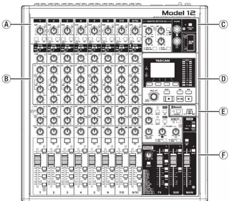
Ⓐ Input channel mixing section-1
Use this section to adjust the input levels of each channel.
⑧ Input channel mixing section-2
Use this section to choose input sources for each channel, adjust compressors and equalizers, and set levels sent to each bus (MAIN MIX L/R, SOLO L/R, AUX1, AUX2/FX, SUB L/R). (see "Input channel mixing section-2" on page 21)
© Equalizer section
Use this section to connect headphones and adjust the output equalizer. (see "Equalizer section" on page 22)
① Screen operation section
Use this section to operate the meter, home and MENU screens shown on the display. (see "Screen operation section" on page 22)
Monitoring section
Switch Bluetooth device input destinations, switch monitoring destinations, and adjust AUX OUTPUT AUX 1/2 jack output levels. (see "Monitoring section" on page 23)
⑤ Analog output adjustment section
Adjust the output levels of the built-in effects, and the MAIN OUTPUT and SUB OUTPUT jacks. (see "Analog output adjustment section" on page 24)
Input channel mixing section-1
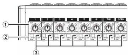
① GAIN knobs and SIG indicators (1-6, 7/8-9/10) Use the GAIN knobs to adjust the input levels of each channel. its SIG indicator will light green when a signal is input (-40dBu or higher: MIC input). If a SIG indicator stays lit red continuously, lower the GAIN knob (+7dBu or higher: MIC input).
② LOW CUT switches (1-6, 7/8-9/10) Turn this switch on (pushed in) to enable low cut filters that cut noise and other sounds at low frequencies. ③ INST switches (1-6, 7/8-9/10) Set according to the MIC/LINE (BAL)/INST TRS input jack input sources. Turn the INST switch on (pushed in) when connecting an guitar, bass or other equipment with high output impedance. Turn the INST switch off (not pushed in) when connecting electronic instruments, audio devices, mics and other equipment.
Input channel mixing section-2
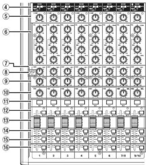
④ MODE switches (1-6, 7/8-9/10)
Use these to select the input source for each channel. (see "Setting the MODE switch" on page 39)
⑤ COMP knobs and indicators (1-6, 7/8-9/10)
Use these knobs to adjust the compression thresholds for the signals input to each channel. When compression is activated, the COMP indicators light.
⑥ EQ knobs (1-6, 7/8-9/10)
- Use these to boost and attenuate the HIGH, MID and LOW bands of each channel.
Setting range: ±15 dB - The central frequencies of the MID bands can be set. Setting range: 100 Hz - 8 kHz (default: 600Hz)
⑦ AUX 1 knobs (1-6, 7/8-9/10)
Use these to adjust the levels of signals sent to the AUX 1 bus.
⑧ POST indicator (shared by all channels)
When this indicator is lit, signals are sent to the AUX 1 bus after the channel faders. (see "Changing the positions that signals are sent to the AUX 1 bus from each channel" on page 57)
⑨ AUX2/FX knobs (1-6, 7/8-9/10)
Use to adjust the levels of the signals sent to the AUX2/FX bus (POST FADER).
⑩ PAN knobs (1-6, 7/8-9/10)
Use to adjust the stereo positions of the signals input to each channel.
NOTE
- When PAN knobs are centered (C), signals are reduced by 3 dB and sent to both left and right MAIN MIX L/R buses.
- When a PAN knob is turned all the way to the left (L), that channel signal is sent only to the left MAIN MIX L/R bus. It is not sent to the right bus.
- When a PAN knob is turned all the way to the right (R), that channel signal is sent only to the right MAIN MIX L/R bus. It is not sent to the left bus.
⑪ REC buttons and indicators (1-6, 7/8-9/10)
Use these to select the channels to record to the SD card.
⑫ MUTE switches and indicators (1-6, 7/8-9/10) When these switches are on (pushed in, MUTE indicator lit), those channels are muted.
⑬ Channel faders (1-6, 7/8-9/10) Use these to adjust the send levels of channel signals.
⑭ MAIN switches (1-6, 7/8-9/10) Turn these switches on (pushed in) to send channel signals to the MAIN MIX L/R bus.
⑮ SUB switches (1-6, 7/8-9/10) Turn these switches on (pushed in) to send channel signals to the SUB L/R bus.
⑯ SOLO switches (1-6, 7/8-9/10) Turn these switches on (pushed in) to send channel signals to the SOLO L/R bus. When these switches are on, the sound of their channels can be heard through the SOLO L/R bus with headphones. When the SOLO MODE screen setting is INPLACE SOLO, the signals of channels that are not on will be muted. (see "Setting the solo function for all channels" on page 57)
Equalizer section
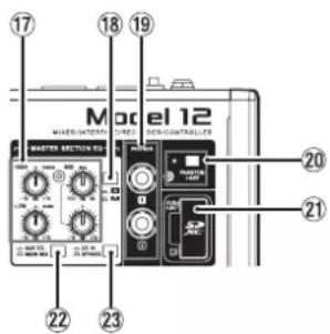
⑰ MASTER SECTION EQ knobs
This 3-band semi-parametric equalizer affects signals output from the MAIN OUTPUT and AUX OUTPUT AUX 1/2 jacks.
⑱ switch
This sets the acuteness of the MID band of the semi-parametric equalizer.
| Switch Meaning | |
| On (A) | The band is acute, making it affect a narrower frequency band. |
| Off (A) | The band is less acute, making it affect a broader frequency band. |
⑲ PHONES jack (1/2)
Use this standard stereo jack to connect stereo headphones. Use an adapter to connect headphones with a mini plug. Use these to monitor signals from the MAIN MIX L/R, AUX 1, AUX 2/FX and SOLO L/R buses. (see "Block diagram / Schéma fonctionnel / Diagrama de bloques" on page 196)
⑳ PHANTOM +48V switch and indicator
Use this switch to supply +48V phantom power to the 1–6, 7/8 and 9/10 XLR jacks on the back of the unit.
The indicator lights when the PHANTOM +48V switch is set to on (pushed in). (see "Setting phantom power" on page 39)
②1 SD card slot
Insert SD cards in this slot. (see "Inserting and removing SD cards" on page 32)
② AUX 1/2/MAIN MIX switch
Set which output signals are affected by the equalizer.
AUX 1/2: Equalizer is applied to signals sent from the AUX 1 and AUX 2/FX buses.
MAIN MIX: Equalizer is applied to signals sent from the MAIN MIX L/R bus.
NOTE
Also set the EQ IN/BYPASS switch to "EQ IN".
⑳ EQ IN/BYPASS switch
When this switch is EQ IN, the equalizer will affect the output signals set with the AUX 1/2/MAIN MIX switch.
When set to BYPASS, the equalizer will not be applied regardless of the AUX 1/2/MAIN MIX switch setting.
Screen operation section
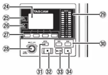
⑳ Display
Shows a variety of information.
⑲ USB indicator
This lights when the USB connection is working.
②6 PFL/AFL indicator
This indicator lights when at least one channel SOLO switch is on or when the AFL switch for the AUX 1 or AUX 2 knob or the FX fader is on.
⑳ Function buttons
The functions of these buttons change depending on the screen shown on the display. The functions shown at the bottom of the display are the currently assigned functions.
NOTE
For convenience, the four buttons under the display are called the function buttons in this manual. From left to right, they are called the F1, F2, F3 and F4 buttons.
⑳ MULTI JOG dial
This dial functions as a dial when turned and as a button when pressed.
Dial functions
- Turn when the Home Screen is open to move the file playback position. (see "Locate function" on page 43)
- When a MENU Screen is open, turn to select items and change setting values. (see "Basic MENU screen operations" on page 29)
Button function
- Press when the Home Screen is open to designate a locate point. (see "Locate function" on page 43)
- When a Menu Screen is open, press to confirm selections and settings (ENTER button function).
⑲ Output level indicators
These show the output levels of the MAIN OUTPUT jacks. When the PFL/AFL indicator is lit, these show the output levels from the SOLO L/R bus.
③0 ◀◀/▶▶ buttons
- When stopped and during playback, press and hold these buttons to search backward/forward.
- When the Home Screen is open, press the ◀ button to locate to the beginning of the current song (00:00:00, which is the zero point).
- When the Home Screen is open, press the ▶▶ button to locate to the end of the current song.
- If the current song has auto punch in or out points set, you can also locate to those points.
- If the current song has marks set, these can also be used to locate to them.
- While pressing the ■ button, press the ◀◀ button to locate to the point where recording last started.
- While pressing the ■ button, press the ▶▶ button to locate to the point where recording last stopped.
- When the SD PLAY Screen is in playback state, press to skip a file. (see "Playing WAV files on SD cards (SD PLAY mode)" on page 64)
③1 MENU button
- When the Meter Screen is open, press to open the Home Screen.
- When the MENU Screen or a menu item settings screen is open, press to return to the Home Screen.
- When the Home Screen is open, press to open the MENU Screen. (see "Menu structure" on page 28) and (see "Basic MENU screen operations" on page 29)
③2 ■ button/indicator
Press to stop playback or recording.
This button lights when stopped.
Press this button when paused to return to the beginning of the song or file.
③3 ▶ /II button/indicator
Press this button to start playback.
This button lights during playback and recording.
This button blinks when paused.
③4 ● button/indicator
Press this button to start recording.
This button lights during recording.
Press this button during playback to start recording (Manual punch in).
Monitoring section
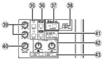
③5 MUTE switch/indicator (AUX 1/AUX 2)
When MUTE switches are on (MUTE indicators lit), signals to the AUX OUTPUT AUX 1/2 jacks are muted.
③6 AFL switches (AUX 1/AUX 2)
When these switches are on (pushed in), the AUX OUTPUT AUX 1/2 jack output signals are sent to the SOLO L/R bus. When these switches are on, the sound of the SOLO L/R bus can be heard through headphones.
③7 PAIRING button and indicator
Press and hold this button to activate Bluetooth pairing mode.
Press when pairing to end pairing mode. (see "Connecting with Bluetooth devices" on page 32)
③8 ASSIGN switch
Sound from the Bluetooth device is sent to channels 9/10 when this switch is set to "9/10" or the MAIN MIX L/R bus when it is set to "MAIN".
⑲ AUX 1/AUX 2 knobs
Use to adjust the output levels of the AUX OUTPUT AUX 1/2 jacks.
④0 PFL/AFL MASTER knob
Use this to adjust the send level from the SOLO L/R bus.
④1 SD MAIN MIX RETURN switch
When this switch is on (pushed in), playback of stereo master files recorded on the SD card is output from the MAIN OUTPUT jacks.
ATTENTION
Be aware that when this switch is on (pushed in), the sound of the MAIN MIX L/R bus is not output.
④2 PHONES knob (1/2)
Use this to adjust the headphone output level.
CAUTION
Before connecting headphones, minimize the volume with the PHONES knob. Failure to do so could result in a sudden loud noise that could harm hearing, for example.
④3 AUX 1/2 /MAIN switch
Turn these switches on to monitor signals from the AUX 1 and AUX 2/FX buses.
Analog output adjustment section
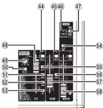
④4 MUTE switch and indicator (FX)
When the MUTE switch are on (pushed in, MUTE indicator lit), the signal from the built-in effect is muted.
④5 MUTE switches and indicators (SUB, MAIN)
When MUTE switches are on (MUTE indicators lit), signals to the SUB OUTPUT/MAIN OUTPUT jacks are muted.
④6 TEMPO indicator
- This lights green when a song that has click sound output set is loaded.
- When the metronome is operating, it lights or blinks as follows. (see "Metronome functions" on page 51)
| Indicator color Meaning | |
| Red | This color lights on the first beat of the setting |
| Green This blinks at the set tempo | |
④7 CLICK button
- When the EFFECT screen is open, tap this button repeatedly at the desired speed to set the delay of the built-in effect. (see "Setting the built-in effect" on page 41)
- When the TAP TEMPO screen is open, tap this button repeatedly at the desired tempo to set the metronome. (see "Making metronome settings" on page 52)
- Press this button when the metronome is stopped to start it at the set tempo. Press this button when the metronome is on to stop it. (see "Starting and stopping the metronome manually" on page 53)
④8 FX fader
Use to adjust the levels of signals sent from the built-in effect to the following buses.
- SOLO L/R bus
- AUX1 bus
- SUB L/R bus
- MAIN MIX L/R bus
④9 TO AUX 1 knob
Use these to adjust the levels of signals sent from the built-in effects to the AUX1 bus.
⑤0 SELECT button
Open the EFFECT Screen and make built-in effect settings. (see "Using the built-in effects" on page 41)
The built-in effect return signal is sent to the following buses.
- MAIN MIX L/R bus
- SOLO L/R bus
- AUX1 bus
- SUB L/R bus
⑤1 MAIN switch (FX)
When this switch is on, signals from the built-in effect are sent to the MAIN MIX L/R bus.
⑤2 SUB switch (FX)
When this switch is on, signals from the built-in effect are sent to the SUB L/R bus.
⑤3 AFL switch (FX)
When this switch is on, signals from the built-in effect are sent to the SOLO L/R bus.
When this switch is on, the sound of the SOLO L/R bus can be heard with headphones.
⑤4 POST REC switch
Select the send position of both the signal recorded to the SD card and the USB audio output.
When this switch is on, signals from after the MAIN fader are recorded to the SD card and the USB audio signals are outgoing.
⑤⁵ AUX 1 switch (FX)
When this switch is on, signals from the built-in effect are sent to the AUX1 bus.
⑤6 MAIN switch (SUB)
When this switch is on (pushed in), the SUB OUTPUT jack output signal is sent to the MAIN MIX L/R bus.
⑤7 SUB fader
Use to adjust the output level of the SUB OUTPUT jacks.
⑤8 MAINfader
Use to adjust the output level of the MAIN OUTPUT jacks.
Rear panel
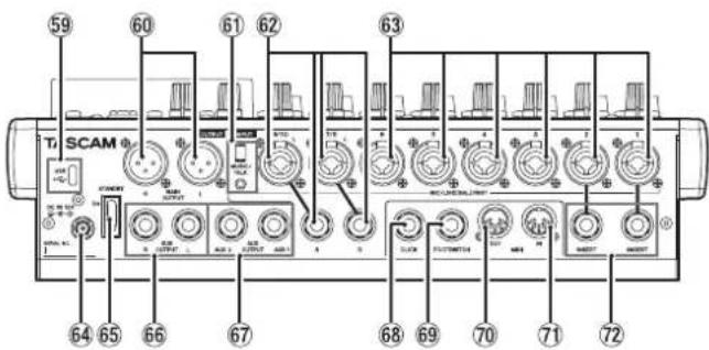
⑤9 USB port
This is a USB Type-C port. Use a USB cable (Type-A to Type-C) to connect the unit to a computer. (see "Connecting with a Computer" on page 65)
ATTENTION
The unit should be connected directly to the computer, not through a USB hub. Moreover, noise could be picked up if the cable is too long.
⑥0 MAIN OUTPUT L/R jacks
These analog outputs are XLR jacks.
• XLR (1: GND, 2: HOT, 3: COLD)
By using a cable with a 4-pole mini plug, the signals output from the MAIN OUTPUT jacks can be sent to the smartphone while simultaneously receiving input from the smartphone.
⑥2 MIC/LINE (BAL)/INST input jacks (7/8-9/10)
These analog inputs are XLR/TRS combo jacks.
• XLR (1: GND, 2: HOT, 3: COLD)
• TRS (Tip: HOT, Ring: COLD, Sleeve: GND)
The balanced XLR jacks are for XLR balanced mic input.
The TRS jacks are for standard TRS stereo line input. If only the L jack in a pair is connected, the same signal was be sent to both left and right channels.
When directly connecting a guitar, bass or other instrument, set the INST switch to on (pushed in).
NOTE
Activating the INST switch only affects the L jack.
⑥3 MIC/LINE (BAL)/INST input jacks (1-6)
These analog inputs are XLR/TRS combo jacks.
• XLR (1: GND, 2: HOT, 3: COLD)
• TRS (Tip: HOT, Ring: COLD, Sleeve: GND)
The balanced XLR jacks are for XLR balanced mic input.
The TRS jacks are for standard TRS mono line input.
When directly connecting a guitar, bass or other instrument, set the INST switch to on (pushed in).
⑥4 DC IN 15V connector
Connect the included AC adapter (PS-M1524) here. (see "Connecting the power" on page 31)
⑥5 STANDBY switch
Press to turn the unit on and off.
CAUTION
Before turning the unit on, lower the volumes of connected equipment to their minimum levels.
Failure to do so might cause sudden loud noises, which could harm your hearing or result in other trouble.
NOTE
Do not do this when the unit is operating (including recording, playing back or writing data to an SD card). Doing so could cause proper recording to fail and recorded data to be lost.
⑥6 SUB OUTPUT L/R jacks
These standard TRS jacks are analog outputs.
• TRS (Tip: HOT, Ring: COLD, Sleeve: GND)
⑥7 AUX OUTPUT AUX 1/2 jacks
These standard TRS jacks are analog outputs.
• TRS (Tip: HOT, Ring: COLD, Sleeve: GND)
ATTENTION
When the AUX OUTPUT AUX 2 jack is in use, the built-in effects cannot be used. (see "Using the built-in effects" on page 41)
⑥8 CLICKjack
This outputs the metronome click sound. (see "Setting the click sound" on page 51)
⑥9 FOOTSWITCH jack
This standard TRS jack is for connecting a footswitch.
• TRS (Tip: FOOTSW1, Ring: FOOTSW2, Sleeve: GND)
NOTE
- This unit was designed to be used with unlatched (momentary) footswitches that have to be pushed to function (shorted when pushed). (see "Setting the footswitch polarity" on page 59)
- Two footswitches can be connected by using a commercially-available Y-cable.
⑦0 MIDI OUT connector
This 5-pin DIN is a standard MIDI output connector.
This outputs MIDI signals sent from the computer.
If the MIDI TIMECODE or MIDI CLOCK/SPP items are set to ON on the MIDI screen, those will also be output. (see "MIDI functions" on page 54)
⑦1 MIDI IN connector
This 5-pin DIN is a standard MIDI input connector.
MIDI signals input through this connector will be sent to the computer.
⑦ INSERT jacks (1-2, standard)
Use these standard TRS jacks to connect external devices (effects).
• TRS (Tip: SEND, Ring: RETURN, Sleeve: GND)
2 - Names and Functions of Parts
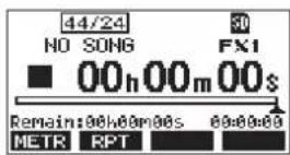
Home Screen
When the Meter Screen is open, press the MENU button to open the Home Screen.
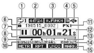
① Repeat playback status
An icon appears when the repeat playback function is on. (see "Repeat playback function" on page 43)
② Song format
This shows the current song file format.
44/15 44.1kHz, 16bit
44/24 44.1kHz, 24bit
48/16 48kHz, 16bit
48/24 48kHz, 24bit
NOTE
If no song is loaded, the operation format of the unit will be shown like 4dr/24 48/24
③ Automatic punch in/out function on/off status
The R.PUNCH appears when the automatic punch in/out function is on. (see "Automatic punch in/out function" on page 44)
④ SD card present status
When an SD card is loaded, the icon appears.
When an SD card is protected, the icon appears.
Since system files cannot be updated when the icon appears, automatic punch in/out settings will not be retained and previously loaded songs will not be loaded when the unit is turned on again.
⑤ USB connection status
During USB connection, the icon appears.
An DELY on appears on the Home Screen when the OUTPUT DELAY function is on (set to ENABLE). (see "13 - OUTPUT DELAY function" on page 74)
⑥ Song name
This shows the name of the current song.
If a song is protected, an icon appears before the file name. (see "Protecting/unprotecting songs" on page 37) If a song has unsaved marks, an icon appears before the file name. (see "Adding marks" on page 50)
⑦ Transport status
This icon shows the recorder operation status.
| Indicator Meaning | |
| ■ | Stopped at the beginning of the file |
| || | Paused |
| ● | Recording |
| ▶ | Playback |
⑧ Playbackposition
The current playback position is shown by a bar.
⑨ Automatic punch in/out point setting status
When the automatic punch in/out function is on, these show the status of automatic punch in/out point setting.
Punch in point
Punch out point
⑩ Remaining time
The remaining time available for recording on the SD card is shown (in hours: minutes: seconds).
NOTE
The remaining time that can be recorded on an SD card varies according to the number of recording channels, song format and SD card capacity.
⑪ Built-in effect status
When a built-in effect is on, the number of the effect in use is shown.
When the built-in effect is off, the F×.H=TE appears.
When the built-in effect cannot be used, the FX.M.40 appears. (see "Using the built-in effects" on page 41)
⑫ Recorder time counter
This shows the elapsed time from the beginning of the song.
⑬ Mark indicators
An icon is shown at each mark.
⑭ Song length
This shows the length of the current song (in hours: minutes: seconds).
⑮ Function button functions
This shows the functions assigned to the function button on the Home Screen.
• F1 METR button: This opens the Meter Screen.
• F2 RPT button: This turns the repeat playback function on/off.
- F3 UNDO button: This returns to the state before the previous operation.
- F3 REDO button: This restores the state after the previous operation.
- FMARK button: This adds/deletes marks.
- F4 CLIC button: Open the METRONOME screen where metronome functions can be set. (see "Function button setting" on page 53)
NOTE
- The F3 button UNDO and REDD indicators appear when those operations are possible.
- Set the F4 button function on the KEY FUNCTION screen. (see "Using mark functions" on page 50) and (see "Function button setting" on page 53)
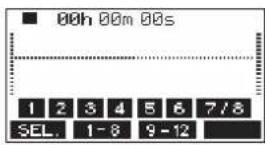
Meters Screen
This shows the levels of the signals being input to the unit.
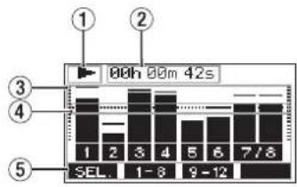
① Transport status
This icon shows the recorder operation status.
② Recorder time counter
This shows the elapsed time from the beginning of the song.
③ Track level meters
These show the signal levels of each channel.
NOTE
The MAIN channels show the MAIN MIX L/R bus levels.
④ Level meter guide
This provides guidance for level adjustment. The guide is shown at the -12dB level.
⑤ Function button functions
This shows the functions assigned to the function button on the Meter Screen.
• F3EL. press to change the input sources shown on the Meter Screen.
- F 1-6 press to show the level meters for channel 1-8 signals on the Meter Screen.
- F9-12 press to show the level meters for channel 9/10 and K8Hgals on the Meter Screen.
Meter Screen details
When the Meter Screen is open, press the F1 WEL on to change the signal sources shown by the meters.
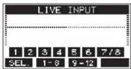
Channel input level screens
The levels of signals input on each channel are shown depending on their MODE switch settings.
LIVE INPUT Screen
This shows the levels of signals being input to the input jacks.
PC RETURN Screen
This shows the levels of signals output from a computer when used as a USB audio interface.
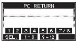
NOTE
Output from the computer, including from Windows Media Player and iTunes, is sent to channels 1-2.
MTR RETURN Screen
This shows the playback signal levels of songs recorded on SD cards.
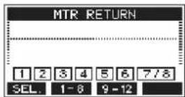
1 2 3 4 Channels that have recording data in the song 1 2 3 4 Channels that do not have recording data in the song
Menu structure
When the Home Screen is open, press the MENU button to open the MENU Screen.
The various menu items are as follows.
| Menu item Function Page | ||||
| SONG SONG Work with songs on an SD card page 36 | ||||
| VAMP | VAMP OFF Disable VAMP playback function page 61 | |||
| I/O EDIT Set VAMP in/out points page 59 | ||||
| I/O ALL CLR Clear all VAMP points page 60 | ||||
| VAMP PLAY Start VAMP playback function page 60 | ||||
| CLICK | SETTING | Set click sound operation and output destination | page 51 | |
| METRONOME | Make specific metronome settings | page 52 | ||
| COUNT IN | Set the count in function | page 53 | ||
| MTR | TRACK EDIT | TRACK CLEAR | Clear specific tracks or all tracks | page 46 |
| IMPORT | Import chosen WAV files to song tracks | page 46 | ||
| TRACK SWAP | Swap song recording files | page 47 | ||
| NORMALIZE | Use the normalize function | page 47 | ||
| AUTO PUNCH | Set the auto punch in/out function | page 44 | ||
| A.PUNCH PRE ROLL | Set the pre-roll point | page 44 | ||
| MIDI | MIDI TIME CODE | Set the MIDI time code | page 54 | |
| MIDI CLOCK/SPP | Set MIDI clock and song position pointer | page 54 | ||
| MIXER | MTR/USB SEND POINT | Set when input signals are sent | page 55 | |
| PHASE | Set the phase of each channel | page 56 | ||
| GAIN BOOST | Use the gain boost function | page 56 | ||
| AUX1 SEND Set the signal sent to the AUX 1 bus page 57 | ||||
| SOLO MODE | Set the solo operation | page 57 | ||
| PHONES MAIN SEL | Set the signal sent to headphones from the MAIN MIX L/R bus | page 58 | ||
| STEREO MIX EXPORT | Use stereo mix export function | page 49 | ||
| SD PLAY Play WAV files on an SD card | page 64 | |||
| STORAGE | SD cards can be accessed from a computer | page 65 | ||
| DAW CONTROLLER | Set the DAW control mode | page 59 | ||
| SYSTEM | INFORMATION | View SD card information, song information and the firmware version | page 62 | |
| DATE/TIME | Date and time settings | page 33 | ||
| SONG NAME | Set the song name format | page 62 | ||
| DISPLAY | Adjust the display | page 34 | ||
| KEY FUNCTION | Set the function of the function button | page 50 | ||
| page 53 | ||||
| FOOTSW | Make footswitch settings | page 58 | ||
| USB AUDIO | PC ← | Set the USB audio mode | page 71 | |
| PC CH1/2 → | Set the USB return channel function | page 71 | ||
| OUTPUT DELAY | Set the OUTPUT DELAY function | page 74 | ||
| OUTPUT PAD | Set the OUTPUT PAD function | page 61 | ||
| INITIALIZE | Restore factory default settings | page 63 | ||
| MEDIA FORMAT | Format the SD card | page 63 | ||
NOTE
The settings for all menu items are retained even when the unit is turned off.
2 - Names and Functions of Parts
Basic MENU screen operations
After using the MENU button to open the MENU Screen, it can be operated in the following manner.
This is an overview of basic operations. Function button assignments differ according to the screen shown on the display.
Selecting items (moving vertically on a page):
Turn the MULTI JOG dial.
Opening a submenu from a page:
Press the MULTI JOG dial.
Confirming a selected item:
Press the MULTI JOG dial (ENTER button function).
Returning to the previous screen without confirming the selected item:
Press the F1 EXIT on.
NOTE
Some menu items are confirmed as soon as they are selected.
Going back one step in a menu:
Press the F1 EXIT on.
Returning to the Home Screen from a MENU Screen:
Press the F1 Homeon.
Menu operation procedures
This explanation uses an example of setting the pre-roll point.
- Press the MENU button to open the Home Screen.
- Press the MENU button to open the MENU Screen.
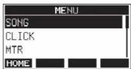
NOTE
Press the F1 Home on to return to the Home Screen.
- Turn the MULTI JOG dial to select different menu items.
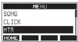
- Press the MULTI JOG dial to open a settings screen.
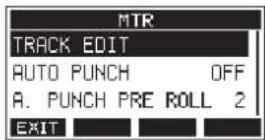
- Turn the MULTI JOG dial to select the menu item to set.
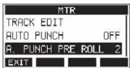
A.PUNCH PRE ROLL selected
- Press the MULTI JOG dial to open the settings screen.
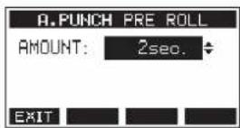
A.PUNCH PRE ROLL Screen open
- Turn the MULTI JOG dial to change the setting.
NOTE
To cancel a setting change, press the F1 EXT on.
-
To set another item on the same screen, press the MULTI JOG dial to move the cursor to the next setting.
-
Repeat steps 3 to 8 as necessary to set other items.
-
Press the F1 EXIT to return to the MENU Screen.
Connecting the power supply and other equipment
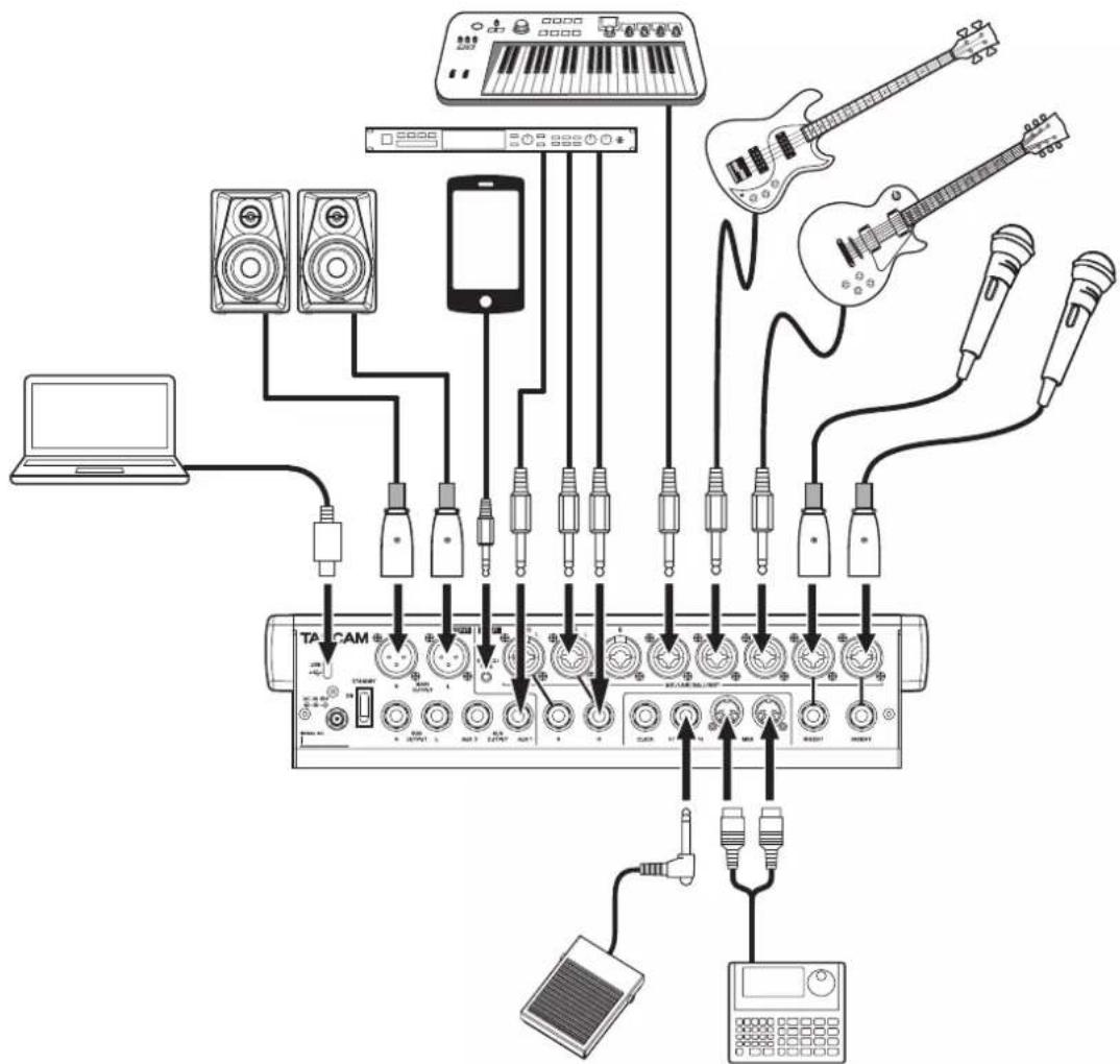
This is an example of Model 12 connections.
Precautions before making connections
- Carefully read the operation manuals of the devices to be connected and then connect them correctly.
- Before making connections, turn this unit and all equipment to be connected off (standby).
- Install all connected devices, including this unit, so that they are powered from the same line. When using a power strip or similar device, be sure to use one that has high current capacity (thick cable) in order to minimize fluctuations in power voltage.
- Before connecting audio equipment, set the following knobs and faders to their lowest values. Failure to do so could cause sudden loud noises from monitoring equipment, and this could damage the equipment or harm hearing.
• GAIN knobs (channels 1-6, 7/8-9/10)
• Channel faders (channels 1-6, 7/8-9/10)
- SUB fader
- AUX 1/AUX 2 knobs
- MAIN fader
- PHONES knob
- Set the PHANTOM +48V switch to off.
flowchart
graph TD
    A["DAHAM"] --> B["Speaker with keyboard"]
    A --> C["Speaker with microphone"]
    A --> D["Speaker with speaker"]
    A --> E["Speaker with microphone"]
    A --> F["Speaker with microphone"]
    A --> G["Speaker with microphone"]
    A --> H["Speaker with microphone"]
    A --> I["Speaker with microphone"]
    A --> J["Speaker with microphone"]
    A --> K["Speaker with microphone"]
    A --> L["Speaker with microphone"]
    A --> M["Speaker with microphone"]
    A --> N["Speaker with microphone"]
    A --> O["Speaker with microphone"]
    A --> P["Speaker with microphone"]
    A --> Q["Speaker with microphone"]
    A --> R["Speaker with microphone"]
    A --> S["Speaker with microphone"]
    A --> T["Speaker with microphone"]
    A --> U["Speaker with microphone"]
    A --> V["Speaker with microphone"]
    A --> W["Speaker with microphone"]
    A --> X["Speaker with microphone"]
    A --> Y["Speaker with microphone"]
    A --> Z["Speaker with microphone"]
    A --> AA["Speaker with microphone"]
    A --> AB["Speaker with microphone"]
    A --> AC["Speaker with microphone"]
    A --> AD["Speaker with microphone"]
    A --> AE["Speaker with microphone"]
    A --> AF["Speaker with microphone"]
    A --> AG["Speaker with microphone"]
    A --> AH["Speaker with microphone"]
    A --> AI["Speaker with microphone"]
    A --> AJ["Speaker with microphone"]
    A --> AK["Speaker with microphone"]
    A --> AL["Speaker with microphone"]
    A --> AM["Speaker with microphone"]
    A --> AN["Speaker with microphone"]
    A --> AO["Speaker with microphone"]
    A --> AP["Speaker with microphone"]
    A --> AQ["Speaker with microphone"]
    A --> AR["Speaker with microphone"]
    A --> AS["Speaker with microphone"]
    A --> AT["Speaker with microphone"]
    A --> AU["Speaker with microphone"]
    A --> AV["Speaker with microphone"]
    A --> AW["Speaker with microphone"]
    A --> AX["Speaker with microphone"]
    A --> AY["Speaker with microphone"]
    A --> AZ["Speaker with microphone"]
    A --> BA["Speaker with microphone"]
    A --> BB["Speaker with microphone"]
    A --> BC["Speaker with microphone"]
    A --> BD["Speaker with microphone"]
    A --> BE["Speaker with microphone"]
    A --> BF["Speaker with microphone"]
    A --> BG["Speaker with microphone"]
    A --> BH["Speaker with microphone"]
    A --> BI["Speaker with microphone"]
    A --> BJ["Speaker with microphone"]
    A --> BK["Speaker with microphone"]
    A --> BL["Speaker with microphone"]
    A --> BM["Speaker with microphone"]
    A --> BN["Speaker with microphone"]
    A --> BO["Speaker with microphone"]
    A --> BP["Speaker with microphone"]
    A --> BQ["Speaker with microphone"]
    A --> BR["Speaker with microphone"]
    A --> BS["Speaker with microphone"]
    A --> BT["Speaker with microphone"]
    A --> BU["Speaker with microphone"]
    A --> BV["Speaker with microphone"]
    A --> BW["Speaker with microphone"]
    A --> BX["Speaker with microphone"]
    A --> BY["Speaker with microphone"]
    A --> BZ["Speaker with microphone"]
    A --> CA["Speaker with microphone"]
    A --> CB["Speaker with microphone"]
    A --> CC["Speaker with microphone"]
    A --> CD["Speaker with microphone"]
    A --> CE["Speaker with microphone"]
    A --> CF["Speaker with microphone"]
    A --> CG["Speaker with microphone"]
    A --> CH["Speaker with microphone"]
    A --> CI["Speaker with microphone"]
    A --> CJ["Speaker with microphone"]
    A --> CK["Speaker with microphone"]
    A --> CL["Speaker with microphone"]
    A --> CM["Speaker with microphone"]
    A --> CN["Speaker with microphone"]
    A --> CO["Speaker with microphone"]
    A --> CP["Speaker with microphone"]
    A --> CY["Speaker with microphone"]
    A --> CZ["Speaker with microphone"]
    A --> DA["Speaker with microphone"]
    A --> DB["Speaker with microphone"]
    A --> DC["Speaker with microphone"]
    A --> DD["Speaker with microphone"]
    A --> DE["Speaker with microphone"]
    A --> DF["Speaker with microphone"]
    A --> DG["Speaker with microphone"]
    A --> DH["Speaker with microphone"]
    A --> DI["Speaker with microphone"]
    A --> DJ["Speaker with microphone"]
    A --> DK["Speaker with microphone"]
    A --> DL["Speaker with microphone"]
    A --> DV["Speaker with microphone"]
    A --> DW["Speaker with microphone"]
    A --> DX["Speaker with microphone"]
    A --> DYD["Speaker with microphone"]
    A --> DYE["Speaker with microphone"]
    A --> DYF["Speaker with microphone"]
    A --> DYG["Speaker with microphone"]
    A --> DYH["Speaker with microphone"]
    A --> DYI["Speaker with microphone"]
    A --> DYJ["Speaker with microphone"]
    A --> DYK["Speaker with microphone"]
Examples of connections to a Model 12
Connecting the power
Use the included AC adapter (TASCAM PS-M1524) to connect a power supply to the unit as shown below.
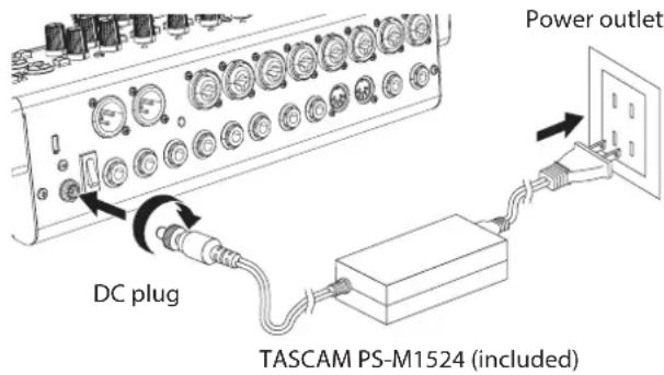
- Connect the included AC adapter (TASCAM PS-M1524) to the DC IN 15V connector on the back of the unit.
- Turn the nut on the DC plug to secure it to the DC IN 15V connector.
ATTENTION
Always connect the included AC adapter (TASCAM PS-M1524) and AC adapter power cord. Use of a different adapter could cause malfunction, fire or electric shock.
Connecting microphones
Dynamic mics
Connect them to the MIC/LINE (BAL)/INST input jacks on the back of the unit.
Condenser mics
When using a condenser microphone that requires phantom power, connect it to a MIC/LINE (BAL)/INST input jack and then turn the PHANTOM +48V switch on (pushed in). (see "Setting phantom power" on page 39)
The PHANTOM +48V indicator lights when the PHANTOM +48V switch is on (pushed in).
Connecting guitars, basses and similar instruments
When connecting a guitar, bass or other instrument with high impedance output (Hi-Z) directly to this unit, use the MIC/LINE (BAL)/INST TRS input jacks, and turn the INST switch on (pushed in) for that jack.
NOTE
When connecting an instrument with active output or when the sound passes through an effects unit, for example, that is connected to this unit, the INST switch does not need to be set to on.
Connecting electronic devices and other audio equipment
Use the following inputs to connect electronic devices and other audio equipment.
- MIC/LINE (BAL)/INST input jacks (1-6, 7/8-9/10)
NOTE
When an INST switch is on (pushed in), input through the MIC/LINE (BAL)/INST TRS input jacks will be unbalanced.
Connecting smartphones/portable audio players
Use the MUSIC/TALK jack to connect a smartphone or portable audio player.
By using a cable with a 4-pole (TRRS) mini plug to connect a smartphone, the signals output from the MAIN OUTPUT jacks can be sent to the smartphone while simultaneously receiving audio signals from the smartphone on channels 9/10.
ATTENTION
- Connecting a cable to the MUSIC/TALK jack disables signals input on channels 9/10 from the MIC/LINE jacks.
- Depending on the specifications of the connected device, normal input and output of sound signals might not be possible.
NOTE
- When signals output from the MAIN OUTPUT jacks are returned to the smartphone, echo will not occur on the smartphone because the sound from the smartphone itself is not included in those output signals.
- When using a stereo mini plug cable, only audio signal input is possible.
Connecting monitor speakers
Connect monitor speakers (powered speakers or an amplifier and speaker system) to the MAIN OUTPUT jacks.
Use the MAIN fader to adjust the speaker volume.
Connecting headphones
Connect headphones to the PHONES jack (standard stereo). The following signals can be monitored according to the SOLO and AFL switch settings.
• Signals output from the MAIN OUTPUT connectors
• Signals output from the SOLO L/R bus
• Signals output from the AUX 1 bus
• Signals output from the AUX 2/FX bus
CAUTION
Before connecting headphones, minimize the volume with the PHONES knob. Failure to do so could result in a sudden loud noise that could harm hearing, for example.
Connecting a computer
Use the included Type-A-Type-C USB cable to connect the unit to a computer USB 2.0 port.
When the USB connection is working, the USB indicator in the screen operation section lights.
ATTENTION
The unit should be connected directly with the computer instead of via a USB hub. Moreover, noise could be picked up if the cable is too long.
Connecting with iOS devices
To connect this unit with an iOS device that has a Lightning connector, use a Lightning to USB Camera Adapter ^® and a use the included USB cable (Type-A to Type-C).
* You must obtain a genuine Apple Lightning to USB Camera Adapter separately.
3 - Preparation
Connecting with Bluetooth devices
This unit can input sound from a computer, portable audio device or other equipment that supports Bluetooth (A2DP).
Pairing
Follow the procedures below to enable communication with a Bluetooth device.
NOTE
Pairing also requires operation of the Bluetooth device. Refer to the operation manual of the Bluetooth device for procedures.
- Set the ASSIGN switch to "9/10" or "MAIN".
- Confirm that the PAIRING indicator on this unit is blinking. If it is unlit, press the PAIRING button.
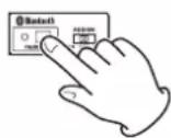
NOTE
When the unit is turned on, it automatically becomes ready for pairing. If 2 minutes pass in pairing mode, it will end. Press this button to reactivate pairing mode when it is disabled.
- Select "Model 12" (this unit) on the other Bluetooth device. When pairing succeeds, the PAIRING indicator will stop blinking and remain lit, and connection with the other device will be complete.
NOTE
- Some older Bluetooth devices require the input of a passkey. Enter "0000" in such cases.
- Pairing will automatically end if connection is not confirmed within two minutes.
- When this unit is turned on, it will automatically try to connect with the Bluetooth device to which it was previously connected. At this time, pairing will automatically end after five minutes if connection is not possible because that Bluetooth device is not turned on or its Bluetooth function is turned off.
Unpairing
The Bluetooth device that is currently connected can be unpaired from the unit.
- Press and hold the PAIRING button for at least two seconds.
- This ends the pairing. The PAIRING indicator will start blinking and the unit will be ready to pair.
Inserting and removing SD cards
Inserting SD cards
Insert an SD card into the SD card slot on the top of the unit to enable playback and recording by this unit.
NOTE
SD cards can be inserted whether or not the unit is on or off.
- Open the SD card slot cover.
- The SD card should be inserted with its label facing left.
- Close the SD card slot cover.
Removing SD cards
Turn the unit off or stop operation before removing an SD card.
CAUTION
Never remove an SD card when the unit is operating (including recording, playing back, or writing data to the SD card). Doing so could cause proper recording to fail, data to be lost, and sudden loud noises from monitoring equipment, which might damage the equipment, harm hearing or cause other trouble.
- Press the SD card in gently to make it to come up.
- Pull the SD card out.
SD card write protection switches
SD cards have write-protection switches that prevent writing new data to them.
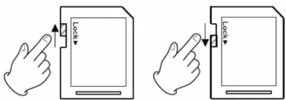
If you slide the write-protection switch to the "LOCK" position, writing will not be possible. Move the write-protection switch to the unlocked position in order to record, erase and otherwise edit data on the card.
Turning the power on and off
CAUTION
- Turn down the volume of the sound system connected to the unit before starting up or shutting down the unit.
- Do not wear connected headphones when turning the unit on and off. Loud noises could damage the speakers or harm your hearing.
Before turning the power on
- Make the following settings on the top of the unit.
• Other knobs → all the way left
• Faders → all the way down
- Switches off (not pushed in)
- Minimize the output levels of audio sources and input levels of amplifiers connected to this unit.
Turning the power on
- Use the STANDBY switch on the back of the unit to turn its power on.
Startup screen
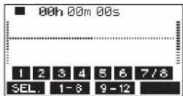
Meter Screen
After the unit starts and the Startup Screen is shown, the Meter Screen will open.
NOTE
-
Press the MENU button to open the Home Screen.
• After the unit is turned on, the PAIRING indicator will blink for a set amount of time. -
Turn connected input audio source devices on.
- Finally turn amplifiers on.
Turning the power off
Before turning the power off, minimize the levels of output faders and knobs, and then follow the procedures above in reverse.
Failure to follow the correct order could result in clicking noises, for example, that might damage equipment.
CAUTION
Do not disconnect the power cord when the unit is operating (including recording, playing back, or writing data to an SD card). Doing so could cause proper recording to fail, recorded data to be lost, and sudden loud noises from monitoring equipment, which might damage the equipment, harm hearing or cause other trouble.
NOTE
When the unit is started up for the first time (or when the built-in clock is reset after being left unused without power for a long time), the DATE/TIME Screen appears before the Startup Screen to allow the date and time of the built-in clock to be set. (see "Setting the built-in clock date and time" on page 33)
Setting the built-in clock date and time
Using its internal clock, this unit includes the date and time when a file is recorded.
- When the recorder is stopped, select DATE/TIME on the SYSTEM Screen, and open the DATE/TIME Screen. (see "Menu operation procedures" on page 29)
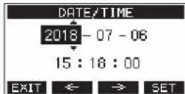
- Turn the MULTI JOG dial to change a value, and press the MULTI JOG dial to confirm it and move the cursor to the next item.
NOTE
Use the F2 🎨 F3 butto move the cursor.
- Change the year, month, day, hour and minute in order, and complete the date and time setting.
- Press the F4 EXIT to confirm the setting and return to the SYSTEM Screen.
NOTE
- When making a setting, you can press the F1 EXIT button to cancel the changes and return to the SYSTEM Screen.
- When setting the time, the time display will be stopped.
- By setting the TYPE item to "DATE" on the SONG NAME Screen, the date and time set here can be used for song names. (see "Setting the song name format" on page 62)
Adjusting the display
The display contrast and brightness can be adjusted.
Adjusting the display contrast
- When the recorder is stopped, select DISPLAY on the SYSTEM Screen, and open the DISPLAY Screen. (see "Menu operation procedures" on page 29)
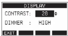
- Adjust the display contrast.
Options: 10 - 40 (default: 28) - Press the MULTI JOG dial to confirm the setting.
- Press the F1 ENIT h to return to the SYSTEM Screen.
Adjusting the display brightness
- When the recorder is stopped, select DISPLAY on the SYSTEM Screen, and open the DISPLAY Screen. (see "Menu operation procedures" on page 29)
- Press the MULTI JOG dial to move the cursor to the DIMMER item.
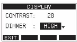
- Adjust the display brightness.
Options: HIGH (default), LOW - Press the MULTI JOG dial to confirm the setting.
- Press the F1 ENIT h to return to the SYSTEM Screen.
Preparing an SD card for use
In order to make an SD card usable in this unit, whether for recording or playback, this unit must be used to create a system file on it first.
ATTENTION
In order to record, this unit must be used to format it first. (see "Formatting SD cards" on page 63)
- "No sys file. Make sys file. Are you sure?" appears in a pop up when a new card or a card formatted by another device is inserted into the unit.
- Press the MULTI JOG dial to create a system file. When system file creation is complete, the Home Screen will reopen.
4 - Managing Songs
This recorder treats each recording data group as one song and manages data by song.
For one song, WAV files are saved for 10 tracks and a stereo master file.
These files are read-only format.
To record or produce music, a song that has already been created needs to be loaded or a new song needs to be created. This chapter describes functions that range from basic operations such as procedures for loading songs and creating new songs to various song management functions.
NOTE
• The maximum recording time for a single song is 23:59:59.
- To use the WAV files from a song in a DAW or other application, copy them to a computer. Do not use the files on the SD card directly.
Viewing the song list
To open a list of songs saved on an SD card, select SONG on the MENU Screen, and press the MULTI JOG dial to open the SONG Screen. (see "Menu operation procedures" on page 29)
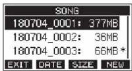
On the SONG Screen, the following functions are assigned to the function buttons.
- Press the F1 EXIT button to return to the MENU Screen.
- Press the F2 DATE button to show the date on the SONG Screen.
- Press the F3 SIZE button to show the size on the SONG Screen.
- Press the F4 NEW button to open the NEW Screen where you can create a new song. (see "Creating a New Song" on page 35)
Song Operation
Select the desired song file on the SONG Screen and press the MULTI JOG dial to open a pop-up menu list with possible song operations.
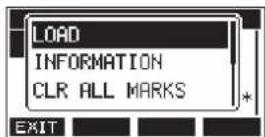
To use a song operation, turn the MULTI JOG dial to select the desired item, and press the MULTI JOG dial.
LOAD/SAVE
Loads the selected song.
When the selected song is the current song, SAVE will appear and information about it will be saved.
INFORMATION
View information about the selected song.
CLR ALL MARKS
Clear all marks in the song.
DELETE
Deletes the selected song.
PROTECT
Protect the selected song.
UNPROTECT
Stop protection of the selected song.
RENAME
Edits the name of the selected song.
Creating a New Song
To record or play with this unit, you must create and load a song. The following procedure can be used to create a new song.
- Open the SONG Screen when the recorder is stopped. (see "Menu operation procedures" on page 29)
- Press the F4 NEW to open the NEW Screen.
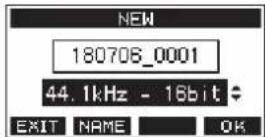
-
Turn the MULTI JOG dial to select the recording file format.
Options: 44.1kHz - 16bit (default), 44.1kHz - 24bit, 48kHz - 16bit, 48kHz - 24bit -
Edit the name of the song as necessary. To edit the name of the song, press the F2 NAME on to open the NAME EDIT Screen.
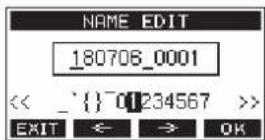
For details about how to edit song names, see "Editing text" on page 37.
TIP
The song name can also be edited later using the RENAME Screen.
- Press the F4 OK to save the currently loaded song and create a new song. When song creation completes, the SONG Screen reopens.
NOTE
- To cancel song creation, press the F1 EXIT button.
- A maximum of 100 songs can be created on a single SD card.
- Songs are created in the "MTR" folder on the SD card.
- When new songs are created, the tempo is set to 120 and the time signature is set to 4/4. (see "Making metronome settings" on page 52)
Loading Songs
Use the following procedure to load the song you want.
- Open the SONG Screen when the recorder is stopped. (see "Menu operation procedures" on page 29)
NOTE
The icon appears for a song currently being loaded. An icon will appear before protected songs.
- Select the song that you want to load and press the MULTI JOG dial to open the menu list pop-up.
- Select LOAD, and press the MULTI JOG dial. After the selected song loads, the SONG Screen will reopen.
Saving the current song
Song information, including marks added during playback of the current song as well as deleted marks, can be saved.
- Open the SONG Screen when the recorder is stopped. (see "Menu operation procedures" on page 29)
- Select the current song, and press the MULTI JOG dial to open the menu list pop-up.
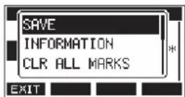
- Select SAVE, and press the MULTI JOG dial. This saves the song information.
ATTENTION
After saving, undoing or redoing the previous operation will no longer be possible.
Viewing song information
You can check the song name (title), sampling frequency, bit rate, size, and date and time last written.
- Open the SONG Screen when the recorder is stopped. (see "Menu operation procedures" on page 29)
- Select the song with information that you want to check and press the MULTI JOG dial to open the menu list popup.
- Select INFORMATION, and press the MULTI JOG dial. The INFORMATION Screen will open.
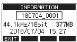
The song name, sampling frequency, bit rate, size, date and time last written will be shown.
- After checking, press the F1 📄 to return to the SONG Screen.
Clearing all marks
This operation clears all marks added to the selected song.
- Open the SONG Screen when the recorder is stopped. (see "Menu operation procedures" on page 29)
- Select the song with the marks that you want to delete and press the MULTI JOG dial to open the menu list pop-up.
- Select CLR ALL MARKS, and press the MULTI JOG dial. The CLR ALL MARKS Screen will open.
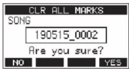
- Press the F4 YES to confirm deletion of marks. When mark deletion completes, the SONG Screen reopens.
ATTENTION
Deleted marks cannot be restored.
Deleting songs
You can delete songs.
Deleting unnecessary songs when the SD card space is low can create more open space.
- Open the SONG Screen when the recorder is stopped. (see "Menu operation procedures" on page 29)
- Select the song that you want to delete and press the MULTI JOG dial to open the menu list pop-up.
- Select DELETE, and press the MULTI JOG dial. The DELETE Screen will open.
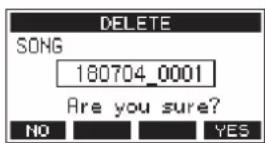
- Press the F4 YE3 to confirm deletion. When song deletion completes, the SONG Screen reopens.
ATTENTION
Deleted songs cannot be restored.
NOTE
- To cancel song deletion, press the F1 NO button.
- The current song cannot be deleted. To delete the current song, load another song first.
Protecting/unprotecting songs
By protecting a song, you can disable editing, recording and deletion operations for that song.
You can protect and stop protecting songs.
-
Open the SONG Screen when the recorder is stopped. (see "Menu operation procedures" on page 29)
-
Select the song that you want to protect or unprotect and press the MULTI JOG dial to open the menu list pop-up.
-
Select PROTECT or UNPROTECT, and press the MULTI JOG dial.
The PROTECT or UNPROTECT screen will open.
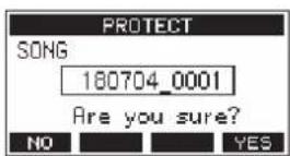
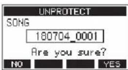
- Press the F4 YES to protect or unprotect the song.
NOTE
To cancel protection or unprotection, press the F1 NO button.
- When song protection or unprotection completes, the SONG Screen reopens.
NOTE
icons appear before songs that are protected in the song list shown for copying, deletion and other operations.
- If you try to execute a prohibited operation (editing, recording, deletion) on a protected song, "Song is protected." will appear in a pop-up message on the display.
Editing song names
- Open the SONG Screen when the recorder is stopped. (see "Menu operation procedures" on page 29)
- Select the song with name that you want to change and press the MULTI JOG dial to open the menu list pop-up.
- Select RENAME, and press the MULTI JOG dial. The RENAME Screen will open.
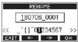
- Edit the song name. For details about how to edit song names, see "Editing text" below.
NOTE
To cancel song name editing, press the F1 E-mail.
- When finished editing the song name, press the F4 OK button to confirm the song name. When song name editing is complete, the SONG Screen reopens.
Editing text
Use these operations to edit text.
Changing the cursor (editing point) position:
Use the F2 ✦ F3 butt
You can also press the MULTI JOG dial to move to the next character.
Deleting the character at the cursor position:
Turn the MULTI JOG dial.
You can input up to 11 characters, including symbols, numbers, and uppercase and lowercase letters.
Leaving a single space open:
Turn the MULTI JOG dial to select a blank space at the left end of any row, and press the MULTI JOG dial.
Canceling edits:
Press the F1 EXIT on.
Confirming the changes:
Press the F4 OK on.
Loading songs created on different TASCAM Model series products
Songs created on TASCAM Model series products with different channel counts can be loaded on this unit.
Use the following procedure to load the song you want.
- Open the SONG Screen when the recorder is stopped. (see "Menu operation procedures" on page 29)
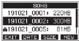
- Select the song that you want to load and press the MULTI JOG dial to open the menu list pop-up. The name of the product used to create the song will be shown next to the LOAD item if it is different from this unit.
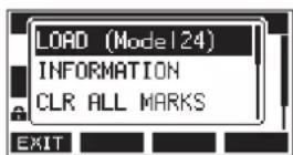
Loading a song made on a Model 24
- Select LOAD, and press the MULTI JOG dial.
After the selected song loads, the SONG Screen will reopen.
Loading a song from a unit with fewer channels on a unit with more channels
When loading a song from a unit with fewer channels on a unit with more channels, empty tracks will be created for the additional channels and the song will be converted for use with the model with more channels before loading.
Example: Loading a song from a Model 12 to a Model 24
| Source song Song after loading | |
| Tracks 1–10 Tracks 1–10 are loaded. | |
| - | Empty tracks are created for tracks 11–22. |
| Track 11 (MAIN MIX L) | This is loaded as track 23 (MAIN MIX L). |
| Track 12 (MAIN MIX R) | This is loaded as track 24 (MAIN MIX R). |
NOTE
- If the SD card is write-protected, the song will be loaded without conversion. See "SD card write protection switches" on page 32 for details about SD card write protection.
- If a song is protected, it will be loaded without conversion. It will automatically be converted if protection is disabled. See "Protecting/unprotecting songs" on page 37 for details about song protection.
Loading a song from a unit with more channels on a unit with fewer channels
When loading a song from a unit with more channels on a unit with fewer channels, some tracks will not be available for recording and playback.
The unit will load tracks up to its number of channels from the song in order from the first.
MAIN MIX L/R tracks will be loaded as MAIN MIX L/R tracks. The song will not be converted.
Example: Loading a song from a Model 24 to a Model 12
| Source song Song after loading | |
| Tracks 1–10 Tracks 1–10 are loaded. | |
| Tracks 11–22 These are not loaded. | |
| Track 23 (MAIN MIX L) | This is loaded as track 11 (MAIN MIX L). |
| Track 24 (MAIN MIX R) | This is loaded as track 12 (MAIN MIX R). |
5 - Basic recording
Selecting the input source
This unit has 10 input jacks (8 combo mic/line and 2 TRS line). The MIC/LINE (BAL)/INST TRS input jacks support high impedance input, including direct guitar input. Turn the INST switch on (pushed in) when connecting an guitar or similar instrument directly.
TIP
Set the INST switch to off, when connecting an electric-acoustic guitar with a built-in preamp or an active electric guitar, as well as when the signal passes through an effect device between the guitar and this unit.
Setting the MODE switch
Using the MODE switch settings of each channel to select their input sources individually.
LIVE: Use the signal from the input jack as the input source.
PC: Use a signal from a computer connected to the USB port as the input source.
MTR: Use a playback signal from the SD card as an input source.
When a MODE switch is set to "MTR", the signal from the input jack on that channel will be recorded.
This function is useful when recording and playing back repeatedly because the monitored sound is automatically switched according to the recording or playback status.
Sounds on channels when in MTR mode
| Transport status | REC button off REC | button on |
| Stop Muted Sound | from input jack | |
| Playing back | Playback sound only | Playback sound only + sound from input jack |
| Recording | Playback sound only | Sound from input jack |
Setting phantom power
When connecting a condenser mic that requires phantom power, press the PHANTOM +48V switch when the recorder is stopped to turn phantom power on/off.
When phantom power is turned on, the PHANTOM +48V indicator lights and a pop-up message appears on the display to confirm turning it on.
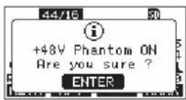
Press the MULTI JOG dial to provide phantom power to the MIC/LINE (BAL)/INST (1-6, 7/8 and 9/10) XLR connectors.
If you set the PHANTOM +48V switch to OFF while the confirmation pop-up message is open, the message will close and phantom power will not be enabled.
CAUTION
Set the following knobs and faders to their minimum values before changing the PHANTOM +48V switch on/off setting. Depending on the connected mics, sudden loud noises from monitoring equipment could occur, and this could damage the equipment or harm hearing.
- GAIN knobs
- Channel faders
- SUB fader
- AUX1/AUX2 knobs
- MAIN fader
- PHONES knob (1/2)
ATTENTION
- Before connecting condenser mics, turn this unit and all equipment to be connected off (standby).
- The PHANTOM +48V switch turns it on/off for the input channels (1-6,7/8-9/10) simultaneously. Do not turn the PHANTOM +48V switch on (pushed in) when connecting a mic that does not require phantom power.
- Do not connect or disconnect mics when the PHANTOM +48V switch is on (pushed in). Doing so could cause a loud noise and might damage this unit and connected equipment.
- Turn the PHANTOM +48V switch on (pushed in) only when using a condenser microphone that requires phantom power. Turning the PHANTOM +48V switch on (pushed in) when a dynamic mic or other mic that does not require it is connected could damage this unit and connected equipment.
- When using condenser mics that require phantom power and dynamic mics together, be sure to use balanced dynamic mics. Unbalanced dynamic mics cannot be used when phantom power is enabled.
- Supplying phantom power to some ribbon mics could break them. If you are unsure, do not supply phantom power to a ribbon mic.
Monitoring
Monitoring is important when recording and mastering. With this unit, monitoring is possible using an external monitoring system (powered monitor speakers or an amp and speakers) or using stereo headphones.
Use the SUB fader and PHONES knob to adjust the level of the monitoring system.
SIG indicators and level meters
The channel 1-6, 7/8-9/10 SIG indicators and level meters shown on the Meter Screen can be used to check the levels of this unit's audio signals.
The level meters are for visually checking signal levels and can also be used to check whether or not signals are being input to this unit.
For example, even if nothing can be heard when monitoring, if the Meter Screen level meters are moving, signals are being input to this unit.
The SIG indicators light green when signals (of at least -40 dB) are input through their channels.
If a SIG indicator lights red, the input source signal is too loud or the GAIN knob is turned up too far.
If the SIG indicator lights red even when the GAIN knob is turned all the way to the left, the input source signal is to loud. Lower its volume.
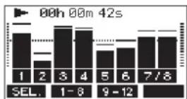
Track level meters (1-6, 7/8-9/10)
The show track playback signal or track input signal levels. Channels for which the MODE switch is set to "MTR" will show the following signal levels according to the operation status.
| REC button Transport status Level meter display | ||
| Unlit PLAY Track playback signal | ||
| Blinking (recording standby) | PLAY | Playback signal Track input + playback signal |
| Stop Track input signal | ||
| Blinking (recording) | Record Track input signal | |
NOTE
When the playback signal is shown, the level of the recorded signal on the track is being shown, so the levels of the level meters cannot be changed.
When the input signal is shown, adjusting channel 1-6, 7/8-9/10 GAIN knobs will change the levels of the level meters.
TIP
Please see "Meter Screen details" on page 27 for details about the Meter Screen.
MAIN MIX L/R level meters (MAIN)
These show the MAIN MIX L/R bus levels.
Recording
This unit can simultaneously record up to 12 tracks, including 10 channel inputs and the MAIN MIX L/R bus.
The following recording operations assume that mics, guitars and other things to record have been connected to the unit, input signals have been assigned as track recording sources, monitoring equipment has been connected and a song has been loaded.
- Press the REC buttons for channel to record.
Press the REC button to start recording standby. It will blink red.
When a MODE switch is set to "MTR", the signal from the input jack on that channel will be recorded. (see "Setting the MODE switch" on page 39)
NOTE
- The MAIN MIX L/R bus does not have a REC button, but it is always in recording standby. The signals of the MAIN MIX L/R bus will always be recorded if the ● button is pressed.
-
When the REC buttons of tracks that already have recordings is blinking, press them to make them unlit.
-
Set the recording levels.
Use the GAIN knobs of each channel to adjust their input levels.
Watch the SIG indicators above and to the right of the GAIN knobs, and set the levels suitably.
At the same time, check that the sound heard through headphones or a monitoring system is not distorted and that an unintended effect has not been set.
NOTE
If an input is too loud, the SIG indicator will light red. If the SIG indicator lights red even when its GAIN knob is turned all the way to the left, lower the volume of the input source.
- Press the ● button.
Recording will start and the ● and ▶/■ buttons will light. The REC buttons for tracks to record will stop blinking and stay lit.
-
When recording has completed, press the ■ button.
-
Use the ◀◀/▶▶ buttons and ■ button, for example to locate to a position you want to check.
TIP
For details about the locate function, see "Locate function" on page 43.
- Press the ▶/Ⅱ button to play the recorded tracks.
Use the channel and MAIN faders to adjust the playback levels.
Use the volume of the monitoring system to adjust the final monitoring level.
Use the PAN knobs of each channel to set the position of each track signal between left and right speakers.
NOTE
- The channel PAN knobs and channel faders control the playback output signals of already recorded tracks or the monitoring volume of input signals. They do not control signals to be recorded.
- If you are not satisfied with a recording, repeat the above procedure from the beginning.
Undoing operations
If you make a mistake operating the unit or want to do a recording over, for example, the operation last conducted can be undone. Editing, recording and other operations can be undone. The following types of operations can be undone.
- Recording operations
• Auto punch in/out operations - Track clearing operations
If a song is loaded or the unit is turned off, Information used for undoing and redoing will be lost, so undoing and redoing previous operations will no longer be possible.
NOTE
Files used for undoing are temporarily saved on the SD card. If you want to delete those files to make more space on the SD card, reload the current song on the SONG Screen.
Undoing the previous operation
- When the Home Screen is open, press the F3 which.
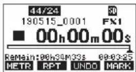
The following confirmation pop-up message will appear.
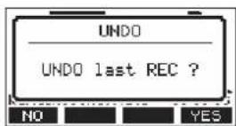
- Press the F4 YES to return to the state before the previous operation.
NOTE
To cancel undoing, press the F1 NO on.
Redoing an undone operation
- After undoing, when the "RECOears on the Home Screen, press the F3 RECObn. The following confirmation pop-up message will appear.
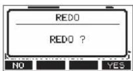
- Press the F4 VC3 h to restore the previous operation and return to the state before undoing.
NOTE
To cancel redoing, press the F1 NO bn.
Using the built-in effects
This unit has built in effects, so you can apply effects without an external effect device.
Channels 1-6 and 7/8-9/10 can have an effect applied. Their signals are sent to the built-in effect by the AUX2/FX bus.
The return signal is sent to the following buses.
- MAIN MIX L/R bus
- SOLO L/R bus
- AUX1 bus
- SUB L/R bus
ATTENTION
When the AUX OUTPUT AUX 2 jack is in use, P.O. N.C's on the Home Screen and the built-in effects cannot be used.
- Use the AUX 2/FX knobs of each channel to adjust the levels of signals sent to the AUX2/FX bus.
- Use the EFFECT Screen to select the type of effect. (see "Setting the built-in effect" on page 41)
- Use the FX fader and TO AUX 1 knob to adjust the return levels for each bus.
Setting the built-in effect
- Press the SELECT button to open the EFFECT Screen.
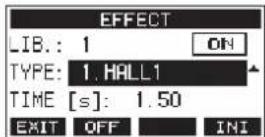
- Turn the MULTI JOG dial, and set the built in effect type.
Options: 1.HALL1 (default), 2.HALL2,
3. ROOM1, 4. ROOM2,
5.PLATE, 6.STUDIO,
7.LIVE, 8.DELAY1,
9.DELAY2, 10.PING PONG,
11.CHORUS, 12.FLANGER,
13.DELAY+HALL1, 14.DELAY+HALL2,
15.CHORUS+HALL1, 16.CHORUS+HALL2
- Press the MULTI JOG dial to select the PARAMETER item. The parameter item is dependent on the selected effect.
5 - Basic recording
- Turn the MULTI JOG, and adjust the set effect. You can check the effect as you change it.
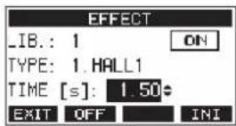
NOTE
- Turn the MULTI JOG dial to change the F4 button function from INI Pre UNDO F4 button to UNDO to the state before turning the MULTI JOG dial.
- Press the F4 INI button to set a parameter value to its default.
- TAP appears for effects that include delay. When the TIME parameter item is selected, the CLICK button can be pressed repeatedly at the desired speed to set the tempo.
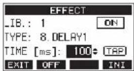
- When the footswitch setting is "TAP", the footswitch can be used instead of the CLICK button for TAP delay input. (see "Setting up the footswitch" on page 58)
- Press the F2 OFF h to turn the built-in effect on/off. The A item on the EFFECT screen shows the built-in effect status.
![EFFECT LIB.: 1 TYPE: 1.HALL1 TIME [s]: 1.50 EXIT ON INI](/content/2026/05/882862/images/06720cde75ce34431985d929be5f2acacc7e45a45586a553f6a1d0e5af4b0e48.jpg)
| Status Meaning | |
| ON (default) The built-in effect is on. | |
| OFF The built-in effect is off. | |
| N/A | The built-in effect cannot be used (because the AUX 2 jack is in use). |
NOTE
When the built-in effect is off, the icon appears on the FX.MUTE Home Screen.
- Press the F1 50T to return to the Home Screen.
Using the library
This unit has a library function that allows up to 10 built-in effect settings to be saved.
Saving effects settings in the library
- Press the SELECT button to open the EFFECT Screen.
- Press the MULTI JOG dial to select the LIB item.
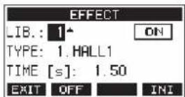
-
Turn the MULTI JOG dial to select the library number to save.
-
Follow the procedures in "Setting the built-in effect" to set the built-in effect. This saves the effect setting in the library.
Using an effect setting saved in the library
- Press the SELECT button to open the EFFECT Screen.
- Press the MULTI JOG dial to select the LIB item.
- Turn the MULTI JOG dial to select the library number with the saved effect setting you want to use. This applies the saved effect setting.
6 - Recorder functions
Locate function
When the Home Screen is open, you can use the MULTI JOG dial to set the locate point.
On the Home Screen, the current position of the recorder is shown as a time in hours (h), minutes (m) and seconds (s). By setting the time in this display area, you can change the current position of the recorder.
Changing the playback position
When the Home Screen is open and the recorder is stopped or playing back, you can use the MULTI JOG dial to set the locate point.
Using the direct locate function to locate
- When the Home Screen is open and the recorder is stopped, press the MULTI JOG dial to enable direct locate mode. A cursor will appear at the location to be changed in the recorder counter.
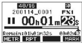
- Turn the MULTI JOG dial to change a value, and press the MULTI JOG dial to confirm it and move the cursor to the next item.
- Change the seconds, minutes and hours in that order to move to that time as the current recorder position.
- Press the ▶/Ⅱ button to start playback or the ● button to start recording from that position.
Repeat playback function
The repeat playback function can be used to play something over and over.
When the Home Screen is open, press the F2 BPT on to set the repeat playback function.
Nothing shown: The current song will keep playing regardless of whether the area is recorded or not.
S1: The current song will play and then stop.
1: The current song will play repeatedly.
Punch in/out function
Punching in and out is a technique used to replace parts of already recorded tracks.
You can start playback of a recording, switch to recording when it reaches the part to be replaced (punch in), and then switch back to playback when the end of that part is reached (punch out) and stop after two seconds.
-
Determine the part you want to replace in advance. Select a point where the replacement audio can be combined well with the original track audio.
-
Press the REC button for the track with the part to be replaced to enter recording standby (REC button blinks).
NOTE
- Set the punch in and out points at least one second apart.
- Punch in recording is not possible when the REC button is on for eight or more channels.
- Start playback before the part to be replaced.
- When the part to be replaced is reached, press the ● button, and perform the part. Recording will start (punch in).
- When the end of the part to be replaced is reached, press the ■ button. The unit will switch to playback and then stop after two seconds.
Using the footswitch to punch in/out
By connecting the recommended TASCAM RC-1F footswitch (sold separately) to the FOOTSWITCH jack on the top of the unit, you can use it to punch in/out.
To use a footswitch to punch in/out, you must set the foot switch function assignment to "PUNCH I/O" in advance. (see "Setting up the footswitch" on page 58)
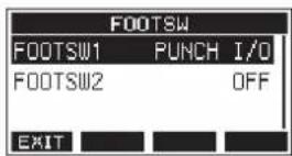
At step 4 above, press the footswitch instead of the ● button, and at step 5 press it again instead of the ■ button.
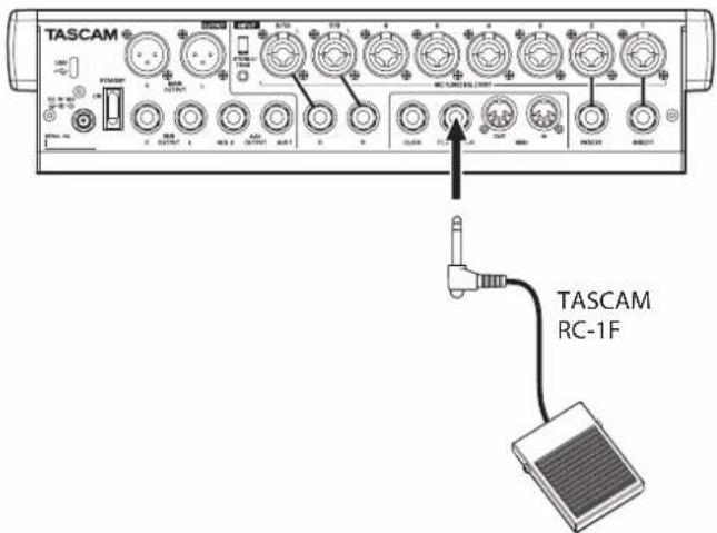
NOTE
This unit was designed to be used with unlatched (momentary) footswitches that have to be pushed to function (shorted when pushed).
Automatic punch in/out function
Using the automatic punch in/out function, you can automatically record between punch in and out points set in advance.
To use the automatic punch in/out functions, start playback from a pre-roll point before the punch in point where recording will start.
Recording will stop when the punch out point is reached, but playback will continue for two seconds before stopping.
Setting the punch in/out points
-
When the recorder is stopped, select MTR on the MENU Screen, and open the MTR Screen. (see "Menu operation procedures" on page 29)
-
Select AUTO PUNCH on the MTR Screen, and open the AUTO PUNCH Screen.
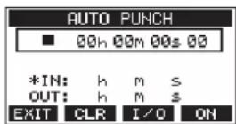
- Press the ▶/■ button to start playback.
- Press the MULTI JOG dial to set the punch in and out points. The set points are shown next to the IN and OUT items.
NOTE
- You can also turn the MULTI JOG dial to set the points.
- Set the punch in and out points at least one second apart.
- Press the F2 CLR button to clear set punch in and out points.
-
Press the F3 I/O button to select either the punch in or out point. An icon will appear next to the selected item.
-
Press the ■ button to stop playback.
-
Press the F4 ON to turn the automatic punch in/out function on.
The R.PUNCH appears on the AUTO PUNCH Screen.
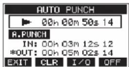
- Press the F1 ENUT to return to the MENU Screen.
TIP
- By setting only the punch in point, you can start recording with automatic punch in and then continue recording until you press the ■ button to stop.
- By setting only the punch out point, you can start recording by pressing the ● button and then stop recording with automatic punch out.
Setting a pre roll point
When using automatic punch in, the amount of playback time before the punch in point can be set (pre roll point).
- When the recorder is stopped, select MTR on the MENU Screen, and open the MTR Screen. (see "Menu operation procedures" on page 29)
- Select A.PUNCH PRE ROLL on the MTR screen to open the A.PUNCH PRE ROLL screen.
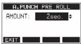
- Set the pre-roll point.
| Option Meaning | |
| OFF | Do not locate to a point before the punch in point. Manually moving to somewhere before the punch in point beforehand will be necessary. |
| 1sec. – 10sec. (default: 2sec.) | Locate to a pre roll point the set time before the punch in point and start playback. |
- Press the F1 📄 to return to the MTR Screen.
Rehearsing punching in and out
You can rehearse before punch in/out recording. In rehearsal, recording will not occur, but monitoring will be the same as if recording.
- Press the MENU button when the recorder is stopped to open the Home Screen. Confirm that the F.PUNCH appears on the Home Screen.
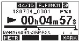
- Press the REC buttons for the tracks you want to record using automatic punch in/out.
NOTE
Punch in recording is not possible when the REC button is on for eight or more channels.
- Press the ▶/Ⅱ button.
Auto punch in/out rehearsal starts.
- The transport starts playback from the pre-roll point. Both track playback and input source signals can be monitored. (see "Setting a pre roll point" on page 44)
- When the punch in point is reached, only the input source signal will be monitored. The ● button will blink showing that it is rehearsal mode.
- When the punch out point is reached, both track playback and input source signals will be monitored. The ● button will become unlit.
- Playback will automatically stop two seconds after the punch out point. The ▶/■ button will blink.
Rehearsal can be repeated.
Using automatic punching in and out
Follow these procedures to punch in and out automatically and record.
-
Confirm that the 6.PHCHears on the Home Screen.
-
Press the REC buttons for the tracks you want to record using automatic punch in/out.
NOTE
Punch in recording is not possible when the REC button is on for eight or more channels.
-
Press the ● button.
-
The transport starts playback from the pre-roll point. Both track playback and input source signals can be monitored. (see "Setting a pre roll point" on page 44)
- When the punch in point is reached, only the input source signal will be monitored. The ● button will light.
- When the punch out point is reached, both track playback and input source signals will be monitored. The ● button will become unlit.
- Playback will automatically stop two seconds after the punch out point. The ▶/■ button will blink.
Clearing tracks
The selected track will be cleared.
- When the recorder is stopped, select MTR on the MENU Screen, and open the MTR Screen. (see "Menu operation procedures" on page 29)
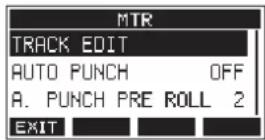
- Select TRACK EDIT on the MTR Screen, and open the TRACK EDIT Screen.
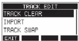
- Select TRACK CLEAR on the TRACK EDIT Screen, and open the TRACK CLEAR Screen.
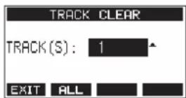
- Turn the MULTI JOG dial to select the track to clear, and press the MULTI JOG dial. A confirmation message will appear.
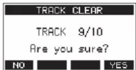
NOTE
Press the F2 FLL on to open a message asking to confirm that you want to clear all tracks.
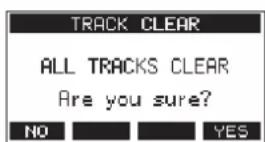
- Press the F4 YES to clear the track(s).
After clearing tracks completes, the TRACK CLEAR Screen will reopen.
NOTE
- To cancel clearing tracks, press the F1 NO button.
- Undoing is possible only for the last cleared track.
Importing tracks
You can import audio files that you have to tracks in the current song.
Files that can be imported to tracks must be WAV (BWF) format (“.WAV” extension).
To import an audio file with a different format (.mp3, etc.) to this unit, it must be converted to a WAV file that matches the format of the song it will be imported into beforehand.
- Connect this unit with a computer. (see "Connecting with a Computer" on page 65)
- Use the computer to copy WAV files on it to this unit's "MUSIC" folder.
- Follow the proper disconnection procedures on the computer before disconnecting the USB cable. (see "Disconnecting" on page 66)
- When the recorder is stopped, select MTR on the MENU Screen, and open the MTR Screen. (see "Menu operation procedures" on page 29)
- Select TRACK EDIT on the MTR Screen, and open the TRACK EDIT Screen.
- Select IMPORT on the TRACK EDIT Screen, and open the TRACK IMPORT Screen. WAV files in the "MUSIC" folder will be shown.
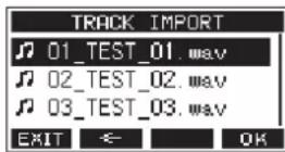
-
Select a WAV file to import.
-
Turn the MULTI JOG dial to select a WAV file.
- Press the MULTI JOG dial when a folder is selected to show its contents.
- Press the F1 EXIT button to return to the MENU Screen.
-
Press the F2 ← button to move up one level.
-
Press the F4 OK h.
A confirmation message will appear if the bit length of the WAV file to be imported differs from the current song.
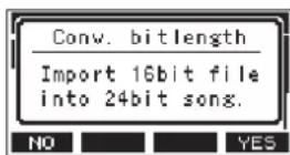
Confirmation message example
- Press the F1 NO button to return to the TRACK IMPORT screen.
- Press the F4 YES button to continue to the TRACK IMPORT screen. In this case, the file will be imported and the bit length will be changed to match the current song.
NOTE
- If there are no openings for tracks to import, an "Import error. No track" pop-up message will appear.
- To cancel importing a track, press the F1 NO button.
- Importing is not possible under the following conditions.
• Not enough open space is available on the SD card
- There are no empty tracks
- If the sampling frequency of the WAV file you are trying to import differs from the current song
Example: Trying to import a 48kHz WAV file when the current song is 44.1kHz
- If there is no file that can be imported, a "No File" pop-up message will appear.
- Select the track to import, and press the F4 YES to import it.
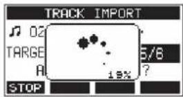
When importing completes, the TRACK IMPORT Screen reopens.
NOTE
- Press the F STOP ton to cancel importing.
- The part of the track imported before canceling will remain; it will not be deleted.
Swapping tracks
Recorded tracks can be swapped with other tracks.
-
When the recorder is stopped, select MTR on the MENU Screen, and open the MTR Screen. (see "Menu operation procedures" on page 29)
-
Select TRACK EDIT on the MTR Screen, and open the TRACK EDIT Screen.
-
Select TRACK SWAP on the TRACK EDIT Screen, and open the TRACK SWAP Screen.
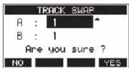
- Turn the MULTI JOG dial to select a track.
Options: 1 (default), 2, 3, 4, 5, 6, 7, 8, 7/8, 9, 10, 9/10, 11, 12, 11/12
-
Press the MULTI JOG dial to move the cursor to the B item.
-
Turn the MULTI JOG dial to select a track.
Options: 1 (default), 2, 3, 4, 5, 6, 7, 8, 7/8, 9, 10, 9/10, 11, 12, 11/12
- Press the F4 YES to swap the track specified in the A and B items.
NOTE
This can be used as a basic bounce function by swapping the signals recorded on tracks 11/12 (the output from the MAIN OUTPUT connectors) to other tracks, and then clearing all the other tracks.
Normalization function
By using the normalization function, the maximum levels of tracks recorded by the MTR can be readjusted within a range of 0 to -20 dB.
Adjusting level differences between tracks makes mixing down easier. Imported tracks and MAIN MIX L/R bus recording files can also be normalized.
Using the normalization function
-
When the recorder is stopped, select MTR on the MENU Screen, and open the MTR Screen. (see "Menu operation procedures" on page 29)
-
Select TRACK EDIT on the MTR Screen, and open the TRACK EDIT Screen.
-
On the TRACK EDIT Screen, select NORMALIZE and open the NORMALIZE Screen.
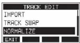
- Turn the MULTI JOG dial to select a track to normalize. Options: 1 (default), 2, 3, 4, 5, 6, 7/8, 9/10, MAIN
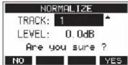
- Turn the MULTI JOG dial to select the normalization level. Options: 0 – -20 dB (default: 0 dB)
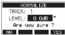
- Press the F4 YES to normalize the specified track.
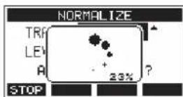
- During conversion, press the F1 STOP button to cancel processing. Normalization will not be conducted if canceled.
A "Process done" message will appear after it completes.
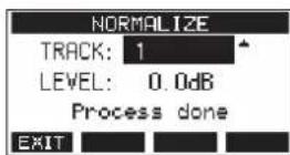
- Turning the MULTI JOG dial to change the track or level will restore the screen to its state in step 4. To continue normalizing other tracks, repeat the procedures from step 4.
Reversing normalization
Tracks that have been normalized can be restored to their previous state by using the undo function. Moreover, after undoing to reverse normalization, the redo function can be used to restore it.
NOTE
If a song is loaded or the unit is turned off, information necessary for undoing and redoing will be lost, so undoing and redoing previous operations will no longer be possible.
- After normalizing, if the F3 function button shows UNDO on the Home Screen, the previous normalization operation can be reversed.
If normalization was canceled or the maximum volume of the track before normalization was the same as the normalized level, the LND on will not be shown.
- To undo the operation, press the F3 UNO on.
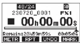
The following confirmation pop-up message will appear.
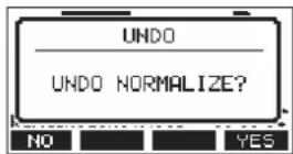
- Press the F4 YCE to restore the track to the volume it had before normalization.
- After undoing, if the F3 REDO function button shows on the Home Screen, the previous undo operation can be reversed.
- To redo the operation, press the F3
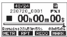
The following confirmation pop-up message will appear.
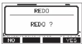
- Press the F4 ME3 h to restore the result of normalization that was undone, reverting to the normalized track volume.
Mixing down
A mixdown is when the volume, panning and other settings of individual track recordings are adjusted and combined into a well-balanced stereo mix.
The MAIN MIX L/R bus does not have a REC button, but it is always in recording standby. Pressing the ● button always records the signals on this bus.
By mixing down with the desired adjustments after recording, stereo mix files can be created from the track audio recorded on each channel.
-
Adjust the recorded sound and play it back.
-
Set the MODE switches of the recorded tracks to "MTR".
- Turn on the MAIN switches of the recorded tracks. (Turn off the MAIN switches of unrecorded tracks.)
-
While using speakers or headphones, for example, to listen to the sounds of all the recorded tracks being output from the MAIN OUTPUT jacks, adjust the channel faders and EQ and PAN knobs.
After confirming, stop playback at the beginning of the song. -
Mix down the playback sound.
-
With the REC buttons off (unlit) on each channel, press the button to create a stereo mix from the playback sounds of all the recorded tracks.
- During mixdown, all fader and EQ and PAN knob adjustments will be recorded from the time that the ● button is pressed and track playback is started until the ■ button is pressed to stop playback.
This will overwrite the existing stereo file.
Stereo mix export function
MAIN MIX L/R bus recording files (mono) can be converted to a single stereo file.
Converted stereo files are saved in the "MUSIC" folder.
Saved files are named according to the song name. For example, the file name will be "181228_0002_2-MIX_01.wav" if the song name is "181228_0002".
If the size of the converted file would exceed 2 GB, multiple files will be created with numbers like "02" and "03" at their ends.
-
Load the song to be exported as a stereo mix in advance. For details about loading songs, see "Loading Songs" on page 36.
-
When the recorder is stopped, select STEREO MIX EXPORT on the MENU Screen, and open the STEREO MIX EXPORT Screen. (see "Menu operation procedures" on page 29)
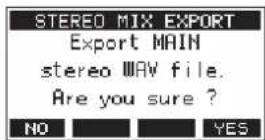
- Press the F4 YES to start conversion.
NOTE
- If a converted file already exists, a message to confirm overriding appears.
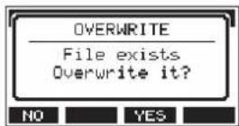
Press the F3 YES on to delete the existing file and start conversion. This operation cannot be undone.
- Conversion is not possible if no MAIN MIX L/R bus file has been recorded. The message shown below will appear.
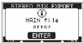
- During conversion, press the F1 STOP button to cancel conversion. A file with the part converted before canceling will remain.
- When conversion completes, the MENU Screen will reopen.
NOTE
Converted files can be played using this unit's SD PLAY mode. For details about playback with the SD PLAY mode, see "Playing WAV files on SD cards (SD PLAY mode)" on page 64.
8 - Mark functions
Marks can be used to cue for playback, for example.
In addition to use with this unit, mark information added to WAV files can be used with software, for example, that supports the BWF format.
Using mark functions
In order to set and clear marks, the Home Screen F4 button function must be switched to MARK
NOTE
When the unit is purchased new, MARKars on the Home Screen. There is no need to change the function of the F4 button before use.
- When the recorder is stopped, select KEY FUNCTION on the SYSTEM Screen, and open the KEY FUNCTION Screen. (see "Menu operation procedures" on page 29)
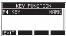
-
Press the MULTI JOG dial to open the F4 KEY Screen.
-
Turn the MULTI JOG dial to select MARK.
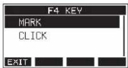
- Press the MULTI JOG dial to confirm the setting. The KEY FUNCTION Screen reopens.
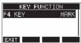
Adding marks
When playing or recording, press the F4 MARK on to add a mark at the current point.
When a mark is added, a pull-up showing the mark number appears at the bottom of the display.
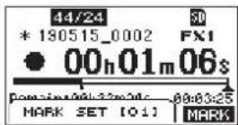
Mark Icons appear below the playback position bar where marks are set.
- The [xx] in the mark name is a number given to all marks that is incremented in order.
- Marks added during recording will automatically be saved in the song when recording stops.
- Marks added during playback will not be automatically saved. Save song information after stopping playback to save mark data. (see "Saving the current song" on page 36)
NOTE
If an icon appears at the beginning of a song name, it has unsaved mark data. Save the song information to save the mark data. (see "Saving the current song" on page 36)
Moving between marks
When stopped, paused or playing back, press the ◀◀ or ▶▶ button to move (skip) to the previous or next mark. When skipping, the mark name appears in a pull-up at the bottom of the display.
Clearing individual marks
Marks can be cleared when stopped or paused.
-
Skip to a mark that you want to delete when stopped or paused. (see "Moving between marks" on page 50)
-
Press the F4 MARK to open the Mark Clear confirmation screen.
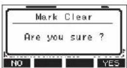
- Press the F4 YES to clear the mark.
NOTE
- Repeat steps 1 - 3 to clear multiple marks.
- To clear all marks in the current song, select the CLR ALL MARKS item from the menu list shown on the SONG Screen. (see "Clearing all marks" on page 36)
Metronome functions
This unit has a built-in metronome.
Click sound and metronome settings can be made.
NOTE
Metronome function settings are saved in the current song. The settings saved in the song can be used the next time it is loaded.
Setting the click sound
The output can be set for the metronome click sound. The setting procedures differ according to the output destination.
Setting the click sound output from the CLICK jack
- When the recorder is stopped, select SETTING on the CLICK Screen, and open the CLICK SETTING Screen. (see "Menu operation procedures" on page 29)
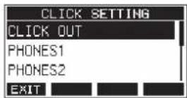
- On the CLICK SETTING Screen, select CLICK OUT, and open the CLICK OUT Screen.
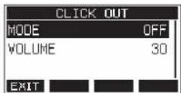
- Select MODE on the CLICK OUT Screen, and open the MODE Screen.
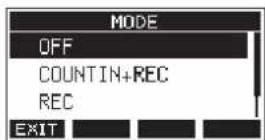
- Turn the MULTI JOG dial to select the click sound output mode.
| Option Meaning | |
| OFF (default) | Click is not output with recording or playback |
| COUNT IN+REC | Click is output during count in and recording |
| REC Click is output during recording | |
| REC&PLAY | Click is output during recording and playback |
-
Press the MULTI JOG dial to confirm the setting. The CLICK OUT Screen reopens.
-
Select VOLUME on the CLICK OUT Screen, and open the VOLUME Screen.
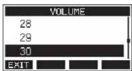
-
Turn the MULTI JOG dial to set the CLICK jack output level. Options: 0–50 (default: 30)
-
Press the MULTI JOG dial to confirm the setting. The CLICK OUT Screen reopens. Starting recording or playback will cause the click to be output according to the setting. When the setting is enabled, the TEMPO indicator flashes in time with the metronome tempo. The metronome signal is not recorded even if set to work during recording.
NOTE
- When the metronome is working, you can monitor the sound of the metronome through connected external speakers.
Note, however, in this case that the metronome sound could also be recorded if you are using a microphone to record in the same room.
- When the metronome is running, the output level settings on various output VOLUME screens can be adjusted, but other items cannot be changed.
- You can use the metronome as a click track to help keep time when recording rhythm guitar or bass, for example, as the first tracks of a song.
- If you want to use the metronome alone for practice, you can either turn each track's fader all the way down during playback or play a song that does not have any recordings.
Setting the click sound output from the PHONES jacks and buses (MAIN MIX L/R, AUX 1, AUX 2/FX, SUB L/R)
-
When the recorder is stopped, select SETTING on the CLICK Screen, and open the CLICK SETTING Screen. (see "Menu operation procedures" on page 29)
-
Select the following items on the CLICK SETTING Screen, and open the corresponding settings screens.
| Option Meaning | |
| PHONES1 | Settings for click sent to the PHONES 1 jack |
| PHONES2 | Settings for click sent to the PHONES 2 jack |
| SUB BUS | Settings for click sent to the SUB L/R bus |
| MAIN BUS | Settings for click sent to the MAIN MIX L/R bus |
| AUX1 Settings for | click sent to the AUX 1 bus |
| AUX2 | Settings for click sent to the AUX 2/FX bus |
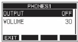
Settings screen when PHONES1 selected
- Select OUTPUT on the settings screen, and open the OUTPUT Screen.
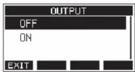
- Turn the MULTI JOG dial to select the click sound sent to the CLICK jack.
| Option Meaning | |
| OFF (default) No click is sent. | |
| ON Click is sent. | |
-
Press the MULTI JOG dial to confirm the setting. The settings screen reopens.
-
Select VOLUME on the screen shown, and open the VOLUME Screen.
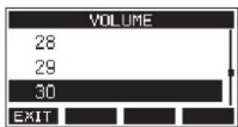
-
Turn the MULTI JOG dial to set the CLICK jack output level. Options: 0–50 (default: 30)
-
Press the MULTI JOG dial to confirm the setting. The settings screen reopens.
Making metronome settings
Specific metronome settings can be made.
-
When the recorder is stopped, select CLICK on the MENU Screen, and open the CLICK Screen. (see "Menu operation procedures" on page 29)
-
Select METRONOME on the CLICK Screen, and open the METRONOME Screen.
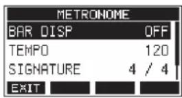
- Turn the MULTI JOG dial to select a metronome setting item. Then, press the MULTI JOG dial. The corresponding setting item screen will open.
BAR DISP
This sets the display of the time counter on the Home Screen.
Options: OFF (default), ON
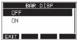
When ON, the time counter on the Home Screen switches to bars and beats, showing the tempo and time signature in the B area.
The maximum number of bars that can be shown is 10000.
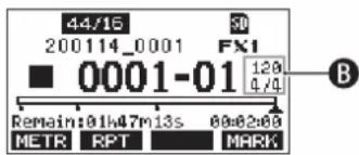
TEMPO
This sets the tempo.
The setting range is from 20 to 250 (BPM). (Default: 120)
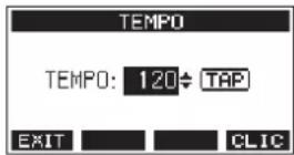
Turn the MULTI JOG dial to set the tempo.
The CLICK button can also be tapped repeatedly at the desired tempo to set it.
When the footswitch function is "TAP", the footswitch can also be used for input. (see "Setting up the footswitch" on page 58)
NOTE
Press the F4 □□□ on to turn the click sound on/off during tempo setting.
SIGNATURE
Set the time signature to 4/4, 3/4, etc.
The setting range is from 1/1 to 12/8. (Default: 4/4)
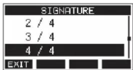
SOUND
This sets the click sound.
Options: CLICK (default), STICK, BELL, KICK, SNARE, PEDAL HIHAT, OPEN HIHAT, CLOSE HIHAT
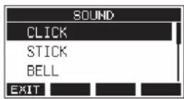
ACCENT
This sets the strength of the click sound accent.
Options: OFF, LOW, MID (default), HIGH
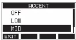
Setting the count in function
When the click sound output setting is set to COUNTIN+REC, counting in before recording is possible.
The click sound pattern played before recording starts can be set.
-
When the recorder is stopped, select CLICK on the MENU Screen, and open the CLICK Screen. (see "Menu operation procedures" on page 29)
-
Select COUNT IN on the CLICK Screen, and open the COUNT IN Screen.
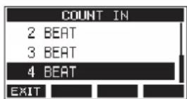
- Turn the MULTI JOG dial to set the count in type.
| Option Meaning | |
| 1 SIGNATURE | One bar of beats for the set SIGNATURE are output. The first beat of the bar is accented. |
| 2 SIGNATURES | Two bars of beats for the set SIGNATURE are output. The first beat of the bar is accented. |
| 4 SIGNATURES | Four bars of beats for the set SIGNATURE are output. The first beat of the bar is accented. |
| 2+4 BEAT | Regardless of the signature setting, one bar of half notes followed by one bar of quarter notes are output. No beat is accented. |
| Option Meaning | |
| 2 BEAT | Regardless of the signature setting, two quarter notes are output. No beat is accented. |
| 3 BEAT | Regardless of the signature setting, three quarter notes are output. No beat is accented. |
| 4 BEAT (default) | Regardless of the signature setting, four quarter notes are output. No beat is accented. |
- Press the MULTI JOG dial to confirm the setting. The CLICK Screen reopens.
Starting and stopping the metronome manually
The metronome can be started and stopped at any time by pressing the CLICK button.
- Press the CLICK button when the metronome is off to start it.
- Press the CLICK button when the metronome is on to stop it.
Function button setting
By changing the F4 button function on the Home Screen from MARK to CLI:METRONOME screen where metronome functions can be set can be opened directly from the Home Screen.
- When the recorder is stopped, select KEY FUNCTION on the SYSTEM Screen, and open the KEY FUNCTION Screen. (see "Menu operation procedures" on page 29)
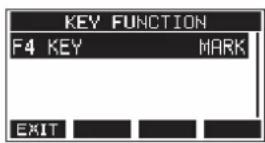
- Press the MULTI JOG dial to open the F4 KEY Screen.
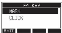
- Turn the MULTI JOG dial to select CLICK.
-
Press the MULTI JOG dial to confirm the setting. The KEY FUNCTION Screen reopens.
-
Open the Home Screen to show that CLICgned to the F4 button.
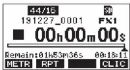
NOTE
Press the F4 Cl.1C on to open the METRONOME Screen.
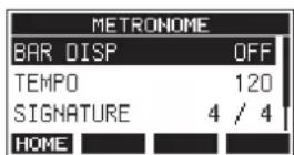
9 - Other functions
MIDI functions
This unit can generate MIDI TIME CODE and MIDI CLOCK when the recorder is playing back or recording.
The generated MIDI data is output from the MIDI OUT connector and simultaneously sent to a computer connected by USB.
A DAW, for example, can be set to synchronize with the MIDI time code from this unit so it can operate in time with the recorder of this unit.
For details, check the operation manual of the hardware or software product being used.
MIDI settings are made on the following screen.
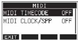
Setting MIDI time code operation
When MIDI time code is enabled, it sends quarter-frame messages during playback and recording. It sends full messages when locating.
- When the recorder is stopped, select MIDI TIMECODE on the MIDI Screen, and open the MIDI TIMECODE Screen. (see "Menu operation procedures" on page 29)
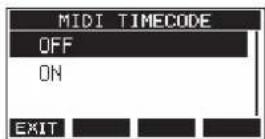
- Turn the MULTI JOG dial to set MIDI time code operation.
| Option Meaning | |
| OFF (default) MIDI | time code is not transmitted. |
| ON MIDI time code | is transmitted. |
NOTE
The MIDI time code frame type sent by this unit is 30 frames per second (non-drop).
- Press the MULTI JOG dial to confirm the setting. The MIDI Screen reopens.
Setting MIDI CLOCK/SPP
When MIDI CLOCK/SPP is enabled, MIDI CLOCK is sent during playback and recording.
Song position pointers are sent when locating.
The MIDI Clock timing and song positions sent depend on the metronome settings.
- When the recorder is stopped, select MIDI CLOCK/SPP on the MIDI Screen, and open the MIDI CLOCK/SPP Screen. (see "Menu operation procedures" on page 29)
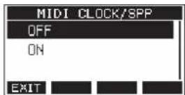
- Turn the MULTI JOG dial to set whether or not MIDI CLOCK/SPP is sent.
| Option Meaning | |
| OFF (default) MIDI | CLOCK/ SPP is not sent. |
| ON MIDI CLOCK/ SPP is sent. | |
- Press the MULTI JOG dial to confirm the setting. The MIDI Screen reopens.
Mixer functions
Selecting the positions that recording signals are sent from each channel
The signals that are sent from each channel for recording to an SD card can be set to before or after the compressor or after the equalizer.
- When the recorder is stopped, select MIXER on the MENU Screen, and open the MIXER Screen. (see "Menu operation procedures" on page 29)
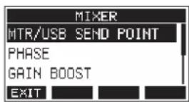
- Select MTR/USB SEND POINT on the MIXER Screen, and open the MTR/USB SEND POINT Screen.
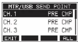
NOTE
Press the F4 FL.I. on to change the settings for all channels at the same time.
- Select the channel to be changed, and press the MULTI JOG dial.
This opens the setting screen for the selected channel.
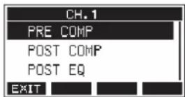
- Turn the MULTI JOG dial to select the send position.
| Option Meaning | |
| PRE COMP (default) | The signal of the channel is recorded to the SD card before the compressor. |
| POST COMP | The signal of the channel is recorded to the SD card after the compressor. |
| POST EQ | The signal of the channel is recorded to the SD card after the equalizer. |
NOTE
The audio sent to the computer depends on the MTR/USB SEND POINT screen setting as follows.
- Press the MULTI JOG dial to confirm the setting. The MTR/USB SEND POINT Screen reopens.
MTR/USB SEND POINT screen settings
The audio sent by computer depends on the Model 12 MODE switch settings and the MTR/USB SEND POINT screen settings.
| MTR/USB SEND POINT COMP EQ MODE switch Audio sent to computer | ||||
| PRE COMP Disabled Disabled | LIVE | Sound from input jacks is sent.PC | ||
| MTR | ||||
| POST COMP Enabled Disabled | LIVE Sound from input jacks is sent. | |||
| PC Sound from computer is sent. | ||||
| MTR | Sound from the MTR is sent. | |||
| POST EQ | Enabled Enabled | LIVE Sound from input jacks is sent. | ||
| PC Sound from computer is sent. | ||||
| MTR | Sound from the MTR is sent. | |||
Setting the phase of each channel
The phase of each channel can be set.
- When the recorder is stopped, select MIXER on the MENU Screen, and open the MIXER Screen. (see "Menu operation procedures" on page 29)
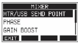
- Select PHASE on the MIXER Screen, and open the PHASE Screen.
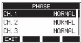
- Select the channel with the signal phase to change, and open its settings screen.
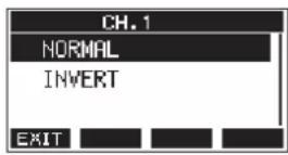
- Turn the MULTI JOG dial to change the signal phase.
| Option Meaning | |
| NORMAL (default) Normal phase | |
| INVERT Inverted phase | |
- Press the MULTI JOG dial to confirm the setting. The PHASE Screen reopens.
Use the gain boost function
The gain boost function uses DSP processing to amplify signals input through mic/line input jacks. Even input sources with low volumes can be used at gain knob positions that are easy to adjust.
NOTE
The gain boost function will also amplify background noise. When an input source has sufficient volume, set its GAIN BOOST function to OFF in order to suppress noise.
- When the recorder is stopped, select MIXER on the MENU Screen, and open the MIXER Screen. (see "Menu operation procedures" on page 29)
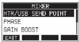
- Select GAIN BOOST on the MIXER Screen, and open the GAIN BOOST Screen.
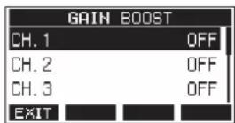
-
Turn the MULTI JOG dial to select the channel with the GAIN BOOST setting to be changed.
-
Press the MULTI JOG dial to open the setting screen for the selected channel.
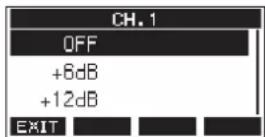
-
Turn the MULTI JOG dial to select the amount of gain boost. Options: OFF (default), +6dB, +12dB
-
Press the MULTI JOG dial to confirm the setting. The GAIN BOOST Screen will reopen.
- The number icons of channels that have gain boost applied will be changed as follows on the channel input level meter and LIVE INPUT screens.
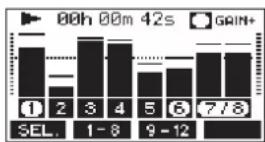
| Display indicator | Meaning |
| This is shown when any channels have gain boost on | |
| These icons show channels with gain boost | |
| These icons show channels with gain boost off |
Changing the positions that signals are sent to the AUX 1 bus from each channel
The positions from which signals are sent from the channels to the AUX 1 bus can be changed.
This setting is shared by channels 1–6, 7/8 and 9/10.
- When the recorder is stopped, select MIXER on the MENU Screen, and open the MIXER Screen. (see "Menu operation procedures" on page 29)
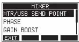
- Select AUX1 SEND on the MIXER Screen, and open the AUX1 SEND Screen.
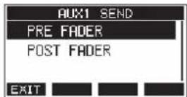
- Turn the MULTI JOG dial to select the signal sent to the AUX 1 bus.
| Option Meaning | |
| PRE FADER (default) | The signal is sent to the AUX 1 bus before adjustment by the channel fader. |
| POST FADER | The signal is sent to the AUX 1 bus after adjustment by the channel fader. |
- Press the MULTI JOG dial to confirm the setting. The MIXER Screen reopens.
Setting the solo function for all channels
This sets the function of the SOLO switch.
This setting is shared by channels 1–6, 7/8 and 9/10.
- When the recorder is stopped, select MIXER on the MENU Screen, and open the MIXER Screen. (see "Menu operation procedures" on page 29)
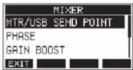
- Select SOLO MODE on the MIXER Screen, and open the SOLO MODE Screen.
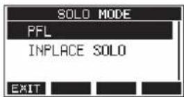
- Turn the MULTI JOG dial to select the solo mode.
| Option Meaning | |
| PFL (default) | Pressing the SOLO switch sends the channel signal to the SOLO L/R bus.Use to check input signals before they are affected by the MAIN MIX L/R bus. |
| INPLACE SOLO | Pressing the SOLO switch mutes the signals of other channels.Use to monitor signals from the MAIN MIX L/R bus after they are affected by channel faders and panning. |
- Press the MULTI JOG dial to confirm the setting. The MIXER Screen reopens.
9 - Other functions
Changing when the signal is sent to headphones from the MAIN MIX L/R bus
This setting can bypass MAIN fader adjustment to the sound when listening to the MAIN MIX L/R bus signal using headphones.
This setting is shared by PHONES 1 and PHONES 2.
- When the recorder is stopped, select MIXER on the MENU Screen, and open the MIXER Screen. (see "Menu operation procedures" on page 29)
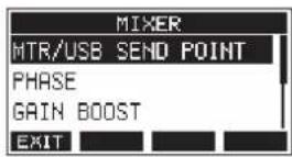
- Select PHONES MAIN SEL on the MIXER Screen to open the PHONES MAIN SEL Screen.
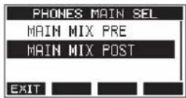
- Turn the MULTI JOG dial to select the signal sent to the headphones.
| Option Meaning | |
| MAIN MIX PRE | The signal is sent to the headphones before adjustment by the MAIN fader. The sound heard through headphones will not be affected by the MAIN fader. |
| MAIN MIX POST (default) | The signal is sent to the headphones after adjustment by the MAIN fader. The sound heard through headphones will be affected by the MAIN fader. |
- Press the MULTI JOG dial to confirm the setting. The MIXER Screen reopens.
Footswitch functions
Setting up the footswitch
Use the FOOTSW Screen to set the footswitch.
Two footswitches can be connected by using a commercially-available Y-cable.* The function and polarity can be set separately for each footswitch.
* Y-cable with 1 standard TRS plug (male) and 2 standard TRS jacks (female) (tip/ring split)
NOTE
When connecting a footswitch directly without using a Y-cable, the FOOTSW1 settings will be used. In this case, set FOOTSW2 to OFF.
TIP
Dual-type unlatched footswitches with standard TRS plugs can also be used.
- When the recorder is stopped, select FOOTSW on the SYSTEM Screen, and open the FOOTSW Screen. (see "Menu operation procedures" on page 29)
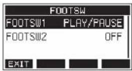
- Select FOOTSW1 or FOOTSW2 from the list, and open the corresponding footswitch settings screen.
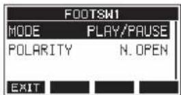
- Select the MODE item, and open the MODE Screen.
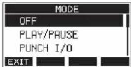
- Turn the MULTI JOG dial to select the function to assign to the footswitch.
| Option Meaning | |
| OFF | No function is assigned to the footswitch. |
| PLAY/PAUSE (default) | Press to start playback when stopped or paused. Press to pause when playing. |
| PUNCH I/O | Press during playback to punch in. Press when recording to punch out. |
| FX MUTE Mute the built-in effect signal. | |
| REC/STOP Start/stop recording. | |
| MARKER Add a mark to the song. | |
| MARK SKIP Move to the next mark. | |
| SONG INCREMENT Load the next song. | |
| TAP | Use in the same way as the CLICK button on the EFFECT and TEMPO screens. |
| VAMP | Use to turn the VAMP function on and off.This has the same function as the F4 VAMP button on the VAMP Playback Screen. |
| VAMP I/O SET | VAMP in and out points can be set on the VAMP Editing Screen, and the VAMP playback function can be controlled.When paused or playing, press once to set a VAMP in point.When paused or playing, press a second time to set a VAMP out point.Press during VAMP playback to turn VAMP playback off. |
- Press the MULTI JOG dial to confirm the assigned function. The FOOTSW screen reopens.
Setting the footswitch polarity
The setting of this unit can be changed according to the polarity of the footswitch being used.
-
When the recorder is stopped, select FOOTSW on the SYSTEM Screen, and open the FOOTSW Screen. (see "Menu operation procedures" on page 29)
-
Select FOOTSW1 or FOOTSW2 from the list, and open the corresponding footswitch settings screen.
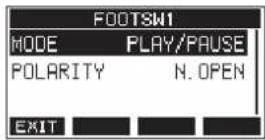
- Select the POLARITY item, and open the POLARITY Screen.
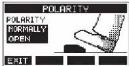
- Turn the MULTI JOG dial to set the footswitch polarity. Select "NORMALLY OPEN" or "NORMALLY CLOSED" so that the actual footswitch movement matches that shown by the illustration on the screen.
Options: NORMALLY OPEN (default), NORMALLY CLOSED
NOTE
When using a TASCAM RC-1F, set the POLARITY switch to "N.OPEN".
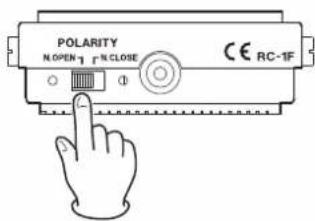
- Press the F1 📋 to return to the FOOTSW Screen.
NOTE
Dual-type footswitches can also be connected. Refer to the operation manual of the footswitch for how to connect and set it.
DAW CONTROL
This unit has DAW control functions. By setting it to DAW control mode, the controls of this unit can be used for basic operation of the DAW application. This includes fader operation, muting, panning, soloing, recording, playing, stopping and other transport functions.
Mackie Control and HUI protocol emulation are supported, so Cubase, Digital Performer, Logic, Live, Pro Tools, Cakewalk and other major DAW applications can be controlled. For details about DAW control mode, download the DAW Control Mode Manual from the page for this product on the TASCAM website (https://tascam.com/us/).
VAMP playback function
The VAMP playback function enables multitrack loop (VAMP) playback between VAMP in and out points set in advance within a song.
Setting VAMP in/out points
These set ranges for VAMP playback within the current song.
-
When the recorder is stopped, select VAMP on the MENU Screen, and open the VAMP Screen. (see "Menu operation procedures" on page 29)
-
Select I/O EDIT on the VAMP Screen, and open the VAMP Editing Screen. Confirm that the V.EEDIT appears on the VAMP Editing Screen.
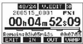
NOTE
Press the F4 UFP on to turn the VAMP playback function on/off.
| Indicator appearance Meaning | |
| v.EDIT (default) | VAMP playback function on |
| v.EDIT | VAMP playback function off |
- When paused or playing back, press the F2 IN and F3 OUT buttons to set VAMP in and out points.
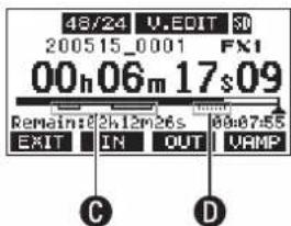
C: Already set VAMP in/out points
D: VAMP in/out points being set
NOTE
- Up to 10 pairs of VAMP in/out points can be set in a single song.
- Set VAMP in and out points at least two seconds apart.
- The ranges between pairs of VAMP in and out points cannot overlap.
9 - Other functions
• VAMP in/out points cannot be set in positions that would exceed the length of the song.
- VAMP in/out points cannot be set to exceed the following times.
| Song file format Time | |
| 44.1 kHz, 16-bit 6:45 | |
| 44.1 kHz, 24-bit 4:30 | |
| 48 kHz, 16-bit 6:12 | |
| 48 kHz, 24-bit 4:08 |
- Press the F1 ☑ with to return to the VAMP Screen.
Moving between VAMP points
When the recorder is stopped, paused or playing back, press the ◀◀ or ▶▶ button to move (skip) from the current location to the previous or next VAMP point. When skipping, the VAMP point name appears in a pull-up at the bottom of the display.
Clearing individual VAMP points
VAMP points can be cleared on the VAMP Editing Screen when the recorder is stopped or paused.
- Skip to a VAMP point that you want to delete when stopped or paused.
- At a VAMP in point, press the F2 ☐ to clear it. At a VAMP out point, press the F3 ☐ on to clear it.
NOTE
Press the F2 IN F3 butt OUT the same time to delete both the VAMP in and out points for the current location.
Clearing all VAMP points
This clears all set VAMP in/out points.
- When the recorder is stopped, select VAMP on the MENU Screen, and open the VAMP Screen. (see "Menu operation procedures" on page 29)
- Select the I/O ALL CLR item on the VAMP Screen, and press the MULTI JOG dial. A clear confirmation screen will open.
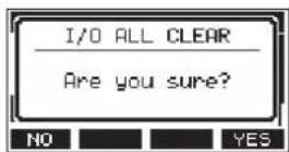
- Press the F4 7C3 in to confirm the clearing of VAMP in/out points. When VAMP in/out point clearing completes, the VAMP Screen reopens.
ATTENTION
Deleted VAMP in/out points cannot be restored.
Setting the VAMP playback operation mode
The VAMP playback function has two operation modes.
NOTE
Recording is not possible when the VAMP playback function is in use.
VAMP automatic playback mode
While playing back using the VAMP playback function, VAMP playback automatically starts when the playback position reaches a VAMP in point.
Pressing the F4 LAMP on while playing back using the VAMP playback function will not turn the function off.

flowchart
graph LR
    A["VAMP-1"] --> B["Oval"]
    C["VAMP-2"] --> D["Oval"]
    style A fill:#f9f,stroke:#333
    style C fill:#f9f,stroke:#333
    style B fill:#ccf,stroke:#333
    style D fill:#ccf,stroke:#333
- Load a song that has VAMP in/out points already set.
- When the recorder is stopped, select VAMP on the MENU Screen, and open the VAMP Screen.
- Select VAMP PLAY on the VAMP Screen, and open the VAMP Playback Screen.
- Press the F3 MODE to switch the VAMP playback mode to automatic. Confirm that the VAMP plears on the VAMP Playback Screen.
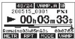
NOTE
- Press the F1 METR button to open the Meter Screen.
- Press the F2 RPT button to switch the repeat playback function.
- Press the F3 MODE button to switch the VAMP playback operation mode.
- Press the F4 VAMP button to turn the VAMP playback function on/off.
| Indicator appearance Meaning | |
| VAMP.A (default) | Automatic operation modeVAMP playback function on |
| VAMP.A | Automatic operation modeVAMP playback function off |
- Press the ▶/Ⅱ button to play the song. When the song playback position reaches the first VAMP interval, VAMP playback will start automatically. VAMP playback of VAMP-1 will continue until the F4URMP button is pressed again.
- Press the F4 VAMP to end VAMP playback of the first VAMP interval and continue playing the song until the next VAMP in point. When the song playback position reaches VAMP-2, VAMP playback will start automatically. VAMP playback of VAMP-2 will continue until the F4 VAMP button is pressed again.
- Conduct the same operations for following pairs of VAMP in/out points.
Manual VAMP playback mode
When the VAMP playback function is activated, it can be turned on manually during playback.
With the VAMP playback function activated, pressing the F4 UAMP button while playing back will turn it on and start VAMP playback.
After VAMP playback completes, it will not restart until the function is turned on again.

-
Load a song that has VAMP in/out points already set.
-
When the recorder is stopped, select VAMP on the MENU Screen, and open the VAMP Screen.
-
Select VAMP PLAY on the VAMP Screen, and open the VAMP Playback Screen.
-
Press the F3 MODE to switch the VAMP playback mode to manual. Confirm that the LIME appears on the VAMP Playback Screen.
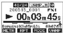
NOTE
- Press the F1 METR button to open the Meter Screen.
- Press the F2 RPT button to switch the repeat playback function.
- Press the F3 MODE button to switch the VAMP playback operation mode.
- Press the F4 VAMP button to turn the VAMP playback function on/off.
| Indicator appearance Meaning | |
| VAMP.M | Manual operation modeVAMP playback function on |
| VAMP.M (default) | Manual operation modeVAMP playback function off |
- Press the ▶/Ⅱ button to play the song.
- Press the F4 VAMP to turn the VAMP playback function on (VAMP.M)
When the song playback position reaches VAMP-1, VAMP playback will start.
VAMP playback of VAMP-1 will continue until the F4URMP button is pressed again.
- Press the F4 VAMP to end VAMP playback at VAMP-1 and continue playing the song.
The VAMP playback function turns off (VAMP) and VAMP playback will not occur even if another VAMP in point is reached.
Disabling the VAMP playback function
- When the recorder is stopped, select VAMP on the MENU Screen, and open the VAMP Screen.
- Select the VAMP OFF item on the VAMP screen, and press the MULTI JOG dial. This disables the VAMP playback function and reopens the Home Screen.
Output pad function
When connecting powered monitor speakers to the MAIN OUTPUT or SUB OUTPUT jacks, the output of this unit could be too high for the input specifications of some monitors, causing distortion in the monitoring sound.
The OUTPUT PAD function can be used to adjust the output to levels suitable for connected monitoring systems.
Setting output attenuation
Setting output attenuation for the MAIN OUTPUT jacks
- When the recorder is stopped, select OUTPUT PAD on the SYSTEM Screen to open the OUTPUT PAD Screen. (see "Menu operation procedures" on page 29)
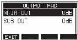
- Select MAIN OUT on the OUTPUT PAD Screen to open a screen where output attenuation can be set for the MAIN OUTPUT jacks.
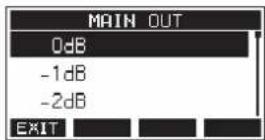
- Turn the MULTI JOG dial to set the output attenuation for the MAIN OUTPUT jacks. Options: 0dB (default) – -40dB (in 1dB steps)
- Press the MULTI JOG dial to confirm the setting. The OUTPUT PAD Screen will reopen.
- Press the F1 📋 to return to the SYSTEM Screen.
Setting output attenuation for the SUB OUTPUT jacks
- When the recorder is stopped, select OUTPUT PAD on the SYSTEM Screen to open the OUTPUT PAD Screen. (see "Menu operation procedures" on page 29)
- Select SUB OUT on the OUTPUT PAD Screen to open a screen where output attenuation can be set for the SUB OUTPUT jacks.
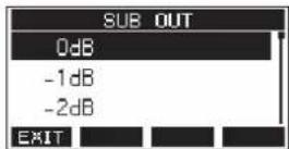
- Turn the MULTI JOG dial to set the output attenuation for the SUB OUTPUT jacks.
Options: 0dB (default) - -40dB (in 1dB steps) - Press the MULTI JOG dial to confirm the setting. The OUTPUT PAD Screen will reopen.
- Press the F1 EXIT to return to the SYSTEM Screen.
10 - Settings and Information
Viewing information
Use the INFORMATION screen to view various types of information about the unit. Follow the procedures below to view the INFORMATION screen.
- When the recorder is stopped, select INFORMATION on the SYSTEM Screen, and open the Information Screen. (see "Menu operation procedures" on page 29)
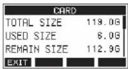
The Information Screen has 3 pages. The CARD page opens first.
- Turn the MULTI JOG dial to cycle through the CARD, SONG and FIRMWARE screens.
CARD Screen
Shows the use status of the currently loaded SD card.
SONG Screen
Shows the number of songs on the loaded SD card.
FIRMWARE Screen
Shows the unit's system firmware version.
- Press the F1 ENITn to return to the SYSTEM Screen.
CARD Screen
The CARD Screen shows the status of the currently loaded SD card.
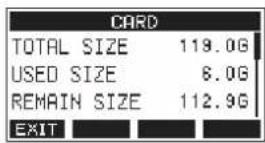
TOTAL SIZE
Shows the total amount of space on the SD card.
USED SIZE
Shows the amount of space used on the SD card.
REMAIN SIZE
Shows the amount of space unused on the SD card.
SONG Screen
The SONG Screen shows the use status of the "MTR" folder.
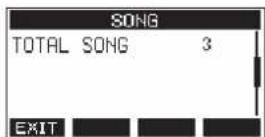
TOTAL SONG
This shows the total number of songs in the "MTR" folder.
FIRMWARE Screen
The FIRMWARE Screen shows the firmware version.
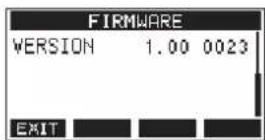
VERSION
This shows the system firmware version of this unit.
Setting the song name format
Set the name format used by the unit for created songs.
- When the recorder is stopped, select SONG NAME on the SYSTEM Screen, and open the SONG NAME Screen. (see "Menu operation procedures" on page 29)
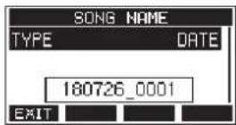
- Set the file name format.
| Option Meaning | |
| DATE (default) | Use the date for the song name.(Example: 180101_0001) |
| WORD | Use the 6-character song name set on the EDIT screen.(Example: TASCAM_0001) |
NOTE
The date is set using the unit's internal clock. (see "Setting the built-in clock date and time" on page 33)
- Press the F1 EXIT to return to the SYSTEM Screen.
Setting the WORD item
To set the characters, select WORD on the TYPE Screen. An EDIT item will appear on the SONG NAME Screen that can open the WORD EDIT Screen.
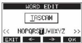
For details about how to set characters, see "Editing text" on page 37.
10 - Settings and Information
Restoring factory default settings
You can restore the various settings stored in the memory of the unit to their factory default values.
Use the following menu procedures to do so.
- When the recorder is stopped, select INITIALIZE on the SYSTEM Screen, and open the INITIALIZE Screen. (see "Menu operation procedures" on page 29)
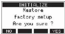
- Press the F4 YES to restore the factory default settings.
- When the setting completes, the SYSTEM Screen will reopen.
NOTE
- Press the F NO ton to cancel execution.
• The date and time setting is not initialized.
Formatting SD cards
Formatting erases all music files on the SD card and automatically creates new "MTR", "MUSIC" and "UTILITY" folders as well as a "tascam_m.sys" file.
ATTENTION
- Formatting an SD card erases all the data on it. This cannot be undone.
-
Always use this unit to format media to be used with it. Operation of this unit might be affected when using an SD card that has been formatted by a computer or other device.
-
When the recorder is stopped, select MEDIA FORMAT on the SYSTEM Screen, and open the MEDIA FORMAT Screen. (see "Menu operation procedures" on page 29)
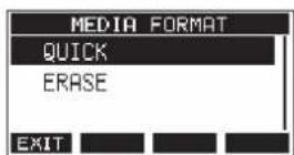
QUICK: Execute quick formatting.
ERASE (Recommendation): Erase and format the card.
- Select the format method, and press the MULTI JOG dial. A confirmation message will appear on the QUICK or ERASE Screen.
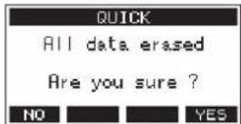
Shown when QUICK selected
NOTE
Press the F1 NO on to cancel formatting and return to the previous screen.
- Press the F4 view to start formatting.
- When formatting is complete, the SYSTEM Screen will reopen.
NOTE
- Pressing the F1 STOP button during an ERASE format will cancel erasure and execute a QUICK format instead.
- The writing speeds to SD cards and other storage media that use flash memory tend to decrease after writing occurs repeatedly.
If the writing speed decreases, this could have a negative impact on recording.
Using the ERASE function of this unit should restore the writing speed of the SD card.*
For this reason, we recommend using the ERASE function at the following times.
- Whenever the card has been written to until it became completely full
- On a regular schedule (about once per month)
• Before starting important recordings
* Writing speed might not be restored depending on the SD card condition (including malfunction and age).
10 - Settings and Information
Playing WAV files on SD cards (SD PLAY mode)
The WAV files in the "MUSIC" folder on an SD card can be played back. (see "Loading WAV files from a computer" on page 66) To play files recorded on this unit, use the stereo mix export function to convert the recorded (mono) files to a single stereo file. Then, use the SD PLAY mode to play it. (see "Stereo mix export function" on page 49)
The following audio file formats can be played back in SD PLAY mode.
WAV: 44.1/48kHz, 16/24-bit
BWF: 44.1/48kHz, 16/24-bit
NOTE
Playback signal is sent from channels 9 and 10.
- Set the channel 9/10 MODE switch to "MTR".
- Set the channel 9/10 PAN/BAL knob to the center position.
- When the recorder is stopped, select SD PLAY on the MENU Screen, and open the SD PLAY Screen. (see "Menu operation procedures" on page 29)
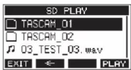
-
Select a file to play back.
-
Turn the MULTI JOG dial to select a WAV file.
- Press the MULTI JOG dial when a folder is selected to show its contents.
- Press the F1 EXIT button to return to the MENU Screen.
- Press the F2 button to move up one level.
NOTE
Only WAV files can be played back. Unsupported files will not be shown.
- Press the F4 PLAY button or ▶/II button to start WAV file playback.
The SD PLAY Screen will show playback status.
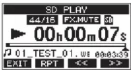
- Press the F1 EXIT button to return to the file selection screen.
- Press the F2 RPT button to turn the repeat playback function on and select the repeat playback mode.
| Display Meaning | |
| No indicator | The folder that contains the currently playing WAV file will play back, and then playback will stop. |
| 1 | The currently playing WAV file will play back repeatedly. |
| 2 | The folder that contains the currently playing WAV file will play back repeatedly. |
- Press the F3 << button to skip to the beginning of the WAV file. Press near the beginning of the WAV file to skip to the beginning of the track before it.
-
Press the F4 >> button to skip to the beginning of the next WAV file.
-
Press the F1 ☑️ with twice to return to the MENU Screen.
11 - Using a computer to transfer data
By connecting this unit with a computer using a use the included USB cable, you can back up song data on the SD card in the unit to the computer, as well restore backed up song data to the unit. You can also export track and stereo master files from songs to the computer and import audio files from the computer.
Backed up data can be restored to other Model 12 units. Since this allows you to freely move files between Model 12 units, you can easily conduct additional recording or mixing at different locations.
ATTENTION
You can conduct the same operations by removing the SD card from the unit and connecting it directly to a computer or by using a card reader instead of using USB to connect the unit and the computer. Turn the unit's power off or stop operation before removing the SD card.
This unit can transfer the following data to a computer.
Entire songs
This unit can transfer all the data for a song from the "MTR" folder to a computer. This operation is called "backing up". Data backed up to a computer can also be transferred to the "MTR" folder, and restored as a song file. This operation is called "restoring".
ATTENTION
Do not change names, delete or otherwise alter individual files inside the "MTR" folder. Doing so could prevent loading data as a song and make proper recording and playback operations impossible.
WAV files
By placing WAV files from the computer into the "MUSIC" folder, you can import them to song tracks. Moreover, WAV files in the "MUSIC" folder can be played back in SD PLAY mode.
Connecting with a Computer
To connect with a computer, use a Type-A to Type-C USB2.0 cable to connect the USB port on the back of this unit to a USB port on the computer.
The USB cable can be connected either before or after turning this unit on.
ATTENTION
- If using this unit as external storage media with a computer, recorder functions, including recording and playback, cannot be used when in USB storage mode.
-
The unit should be connected directly with the computer instead of via a USB hub. Moreover, noise could be picked up if the cable is too long.
-
Use a USB cable (Type-A to Type-C) to connect the computer to this unit's USB port.
-
On the MENU Screen, select STORAGE to open the STORAGE Screen. (see "Menu operation procedures" on page 29)
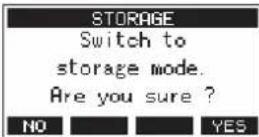
- To connect with the computer, press the F4 YES h. The unit enters USB storage mode and connects with the computer.
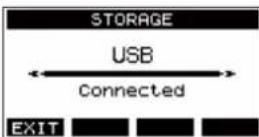
Make sure that the SD card is inserted properly.
- This unit appears on the computer as an external drive named "TASCAM_M" (if the card was formatted by this unit).
NOTE
Follow these procedures to open This PC.
Windows 10
Left-click the Windows Start button, and from Windows System select "PC".
Windows 8.1
Left-click the Windows Start button, click the down arrow icon on the Start screen, and select This "PC" under Windows System in the application list.
Windows 7
Left-click the Windows Start button, and select "Computer" in the Start menu.
11 - Using a computer to transfer data
- Click the "TASCAM_M drive" on the computer to show the "MTR", "MUSIC" and "UTILITY" folders.
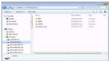
ATTENTION
- This unit receives power through its power cord. It cannot be powered by USB.
- Do not disconnect the power cord or turn off the power during data transfer. Data will be lost if the power is interrupted during transfer. Lost data cannot be restored.
- Do not change the names of folders in "TASCAM_M".
NOTE
- Do not change names, delete or otherwise alter individual files inside the "MTR" folder.
-
The "UTILITY" folder is used when updating the unit system, for example.
-
Press the F1 with to return to the Meter Screen.
Disconnecting
Before disconnecting the USB cable, use the proper procedures for your computer to unmount the unit (as an external drive). See the computer's operation manual for instructions about how to unmount an external volume.
Press the F1 EMT on to disconnect from the computer and return to the Home Screen.
Loading WAV files from a computer
- Use a USB cable (Type-A to Type-C) to connect the computer to this unit's USB port. (see "Connecting with a Computer" on page 65)
- Click the "Model 12" drive on the computer to show the "MTR", "MUSIC" and "UTILITY" folders.
- Drag and drop files on the computer that you want to transfer to the unit to the "MUSIC" folder.
ATTENTION
- The "UTILITY" folder is used when updating the unit system, forexample.
- Do not change names, delete or otherwise alter individual files inside the "MTR" folder. Doing so could prevent loading data as a song and make proper recording and playback operations impossible.
TIP
- You can manage the content of "MTR" or "MUSIC" folders from the computer.
- You can create subfolders in the "MUSIC" folder up to the second level for use with this unit. The Model 12 cannot recognize sub-folders and files located at the third layer level or below.
12 - USB audio interface functions
Installing the dedicated software
To use this unit as a USB audio interface with a Windows computer, dedicated software must be installed on the computer.
Download the latest software from the product page on the TEAC Global Site (https://teac-global.com/).
Installing the dedicated software will install a driver and a Settings Panel application.
ATTENTION
Before starting to install software, quit other applications.
NOTE
With a Mac, the standard OS driver will be used, so installation of dedicated software is not strictly necessary. We recommend installing this software, however, because it has a notification function about updates for the unit firmware and software.
Installing the Windows dedicated software
ATTENTION
- Complete installation of the Windows dedicated software on the computer before connecting the unit to it with the USB cable.
- If you connected the unit to the computer using the USB cable before installing the Windows dedicated software and the "Found New Hardware Wizard" launched, close the Wizard and disconnect the USB cable.
Windows dedicated software installation procedures
- Download the latest Windows dedicated software from the TEAC Global Site (https://teac-global.com/) and save it on the computer to be used with the unit.
- Uncompress the saved software (zip file) on the computer desktop or another location.
- Double-click the "TASCAM_Model_Mixer_Installer_x.xx.exe" file in the folder that appears after uncompression to launch the installation software.
ATTENTION
If you open a zip file without decompressing it and doubleclick the "TASCAM_Model_Mixer_Installer_x.xx.exe" file in the folder that opens, installation will not start. Right-click the zip file and select "Extract All", for example, to decompress it and then try again.
-
When a "Security Warning" or "User Account Control" screen appears, click the "Yes" button.
-
Read the contents of the License Agreement, and select "I accept the agreement" if you agree to the terms. Then, click the "Next >" button.
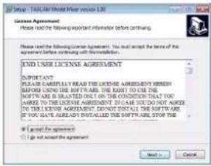
- Next, click the "Install" button.
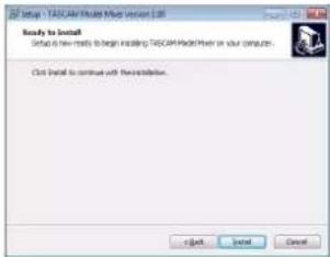
- Next, click the "Install" button to start installation (Windows 7 only).
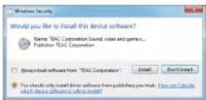
- The following screen appears when installation has completed. Click the "Finish" button.
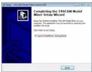
The installer will quit and the Windows Settings Panel will launch.
NOTE
The first time you connect the unit by USB to the computer after installing the software, installation of the device driver will be executed. Some time might be necessary before the unit is recognized because Windows Update will be automatically searched at this time. If the unit is still not recognized after a while, open the software installation screen from the notification area at the bottom right of the computer display, and click "Skip obtaining driver software from Windows Update" to stop the search.
12 - USB audio interface functions
Installing the Mac dedicated software
NOTE
• Install the Mac dedicated software on the computer before connecting the unit to it with the USB cable.
- Depending on the Gatekeeper setting, a warning message might appear during installation. Please see "Working with Gatekeeper" on page 68 for information about Gatekeeper.
Mac dedicated software installation procedures
- Download the latest Mac dedicated software for the operating system you are using from the TEAC Global Site (https://teac-global.com/) and save it on the computer to be used with the unit.
- Double-click "TASCAM_MODEL MIXER_Installer_x.xx.dmg", which is the saved disk image file for the Mac dedicated software, and double-click "ModelMixer_Installer.pkg" inside the folder that opens.

ModelMixer_installer.pkg
NOTE
Depending on the computer's settings, the downloaded zip file might not have been uncompressed automatically. In this case, uncompress the zip file first and then double-click the disk image file.
- When the installer starts, click the "Continue" button.
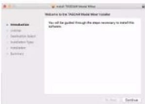
- Next, select the desired language and click the "Continue" button.
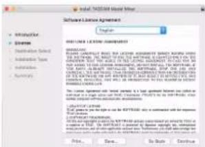
- Click the "Read License" button and check the contents of the Software License Agreement. If you agree to the contents of the license, click "Agree". Then, click the "Next" button.
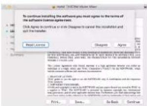
- Next, click the "Install" button to start installation.
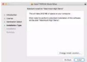
- The following screen appears when installation has completed. Click the "Close" button.
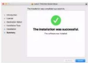
Working with Gatekeeper
When using macOS, depending on the Gatekeeper security function setting, a warning message might appear during installation.
The solution depends on the warning message shown. See the following explanations for details.
When the Gatekeeper setting is "Allow applications downloaded from: the Mac App Store"
The following security warning might be shown: "ModelMixer_Installer.pkg' can't be opened because it was not downloaded from the Mac App Store."
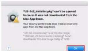
In this case, click the "OK" button to close the message. Then, control-click (or right-click) the file and click "Open" in the menu.
When the "ModelMixer_Installer.pkg" can't be opened because it was not downloaded from the Mac App Store. Are you sure you want to open it?" security warning message appears, click the "Open" button.
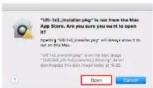
This warning message might also appear when the Gatekeeper setting is something other than "Allow applications downloaded from: the Mac App Store."
12 - USB audio interface functions
The file still might not open and "ModelMixer_Installer.pkg" can't be opened because it was not downloaded from the Mac App Store." might appear again.
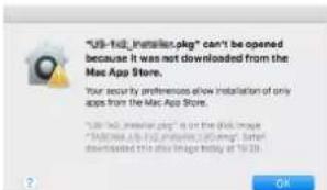
In this case, copy the file from the folder where it is to the desktop or another folder, and then open it. Alternatively, change the Gatekeeper settings to "Allow apps downloaded from: App Store and identified developers" and try opening it again.
When the Gatekeeper setting is "Allow applications downloaded from: the Mac App Store"
"TASCAM_MODEL MIXER_Installer_x.xx.dmg' is an application downloaded from the Internet. Are you sure you want to open it?" might appear as a security warning message. In this case, click the "Open" button.
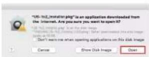
Changing the Gatekeeper setting
The Gatekeeper setting can be changed using the "Allow applications downloaded from:" item on the "General" page of the "Security & Privacy" pane of the System Preferences. To change this, you must click the lock icon (💡) at the bottom left and enter a password to unlock the settings.
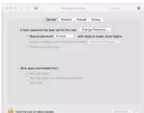
This setting will lock again when you close the System Preferences by clicking the button or typing command-Q, for example, or when you click "Show All" to close the open pane.
ATTENTION
Changing the Gatekeeper settings could result in security risks.
If you changed the Gatekeeper setting to decrease security (use one of the lower settings), set it back to the original setting after updating the driver and/or firmware.
Uninstalling the dedicated software
NOTE
Normally, there is no need to uninstall the dedicated software. Follow these procedures if a problem occurs or you no longer intend to use the unit with the computer.
Uninstalling the Windows dedicated software
- Open the "Uninstall or change a program" screen using the procedures for the operating system being used (Windows 10/Windows 8.1/Windows 7).
- Select "TASCAM Model_Mixer x.xx" from the list, and double-click it.
- Then, follow the instructions that appear on the screen.
Uninstalling the Mac dedicated software
Delete "TASCAM Model_Mixer" from the Application folder to complete uninstallation.
Opening the Settings Panel
Open the Settings Panel in the following manner.
Windows
- From the "Start" menu select "TASCAM Model Mixer" under "TASCAM"
Mac
- On the Launchpad, click "TASCAM Model Mixer".
- Using the Finder, open the Applications folder and click "TASCAM Model Mixer" to open the Settings Panel.
12 - USB audio interface functions
Settings Panel overview
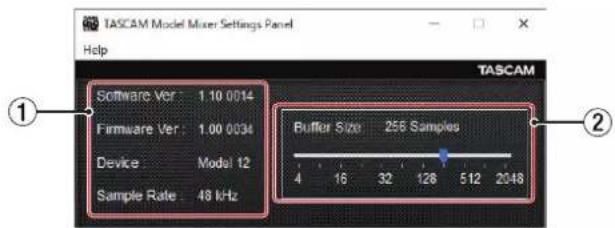
Windows Settings Panel
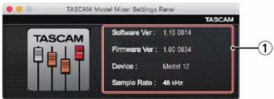
Mac Settings Panel
① Status display area
This shows the current status of the software.
| Item displayed Meaning | |
| Software Ver This is the software version. | |
| Firmware Ver | This is the firmware version used by the connected unit. |
| Device | This is the name of the connected unit. ("No Device" is shown when no device is connected.) |
| Sample Rate | This shows the sampling frequency of the current song.If an SD card is not loaded, this shows the sampling frequency set by the computer. |
② Buffer Size (Windows only)
You can adjust the size of the buffer used to handle the audio input and output signals transferred to and from the computer.
Smaller buffer sizes result in less audio signal delay (latency), but require high-speed processing by the computer.
If the processing cannot keep up, for example, due to other system operations, clicking and popping noises might occur and the audio signal might even drop out.
Increasing the buffer size will stabilize operation and suppress negative effects on audio signals, but the delay in audio signals sent to the computer will increase.
You can use the slider on the panel to adjust the buffer size for this unit according to the use conditions.
Options
4, 8, 16, 24, 32, 64, 128, 256 (default), 512, 1024, 2048
Notification function
If the computer you are using is connected to the Internet, the latest information about unit firmware and software, for example, can be shown when the Settings Panel is launched.
NOTE
Put a check in the "Do not show the same message again" checkbox to prevent the same message from being shown the next time it is launched.
Setting Sound Properties
1. Open the OS Control Panel.
NOTE
Follow these procedures to open the Control Panel.
Windows 10
Left-click the Windows Start button, and from "WindowsSystem" select "Control Panel".
Windows 8.1
Right-click the Windows Start button, and select "Control Panel".
Windows 7
Left-click the Windows Start button, and select "Control Panel" in the Start menu.
2. Double-click "Sound" in the Control Panel.
NOTE
If the Control Panel is set to be viewed as icons, a "Sound" icon will appear.
- On the "Playback" page, right-click "Model 12", and click "Set as Default Device" in the pop-up menu that appears.
When you do this, the green check mark appears next to the selected device.
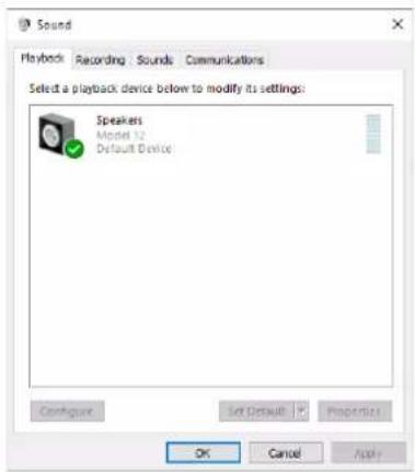
Windows 10 screen
NOTE
Set the default device according to the ASIO device being used on the Recording tab in the same manner as on the Playback tab.
- After completing the setting, click the "OK" button.
- Launch Windows Media Player and start playback to input the playback sound from the computer to channels 1 and 2 on the Model 12. (MODE switches: PC)
NOTE
- If you change the setting while Windows Media Player is running, the software will not recognize that the device has been changed. In this case, restart Windows Media Player.
- If you still cannot hear sound after making the settings and completing the procedures above, restart the computer.
- If you make this setting, sound will be output through this unit, but no sound will be output from the computer's speakers or headphone jack.
Simultaneous ASIO/WDM playback
The driver for this unit can simultaneously play ASIO output from a DAW and WDM output from Windows Media Player, for example. The sample rates of both sources must be set to the same value for simultaneous playback to be possible. Moreover, the sample rate must also be set to the same value for both playback and recording in the Windows Sound Properties.
When the sample rates are the same
Example: Windows (WDM) at 44100 Hz, ASIO at 44100 Hz The Windows audio and ASIO sound are mixed and played simultaneously.
When the sample rates are different
Example: Windows (WDM) at 48000 Hz, ASIO at 44100 Hz Only sound from a DAW and other ASIO sources are output. Sound from Windows Media Player and other WDM sources are not output.
When the DAW is shut down, for example, and output from ASIO sources stops, sound from Windows Media Player and other WDM sources will become audible.
Make USB audio settings
Setting the USB audio mode
The sound input to the computer can be changed to allow the MAIN MIX L/R bus signal to be sent to communication applications and streaming software.
- When the recorder is stopped, select USB AUDIO on the SYSTEM Screen, and open the USB AUDIO Screen. (see "Menu operation procedures" on page 29)
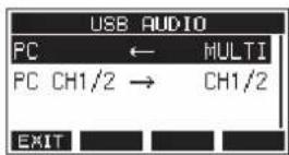
- Select PC ← on the USB AUDIO Screen, and open the TO PC Screen.
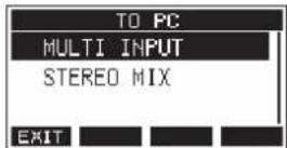
- Turn the MULTI JOG dial to select the audio to input to the computer.
| Option Meaning | |
| MULTI INPUT (default) | The inputs of channels 1–6, 7/8 and 9/10 and the output of the MAIN MIX L/R bus are input to USB channels 1–12. |
| STEREO MIX | The output of the MAIN MIX L/R bus is input to USB channels 1–2. |
- Press the MULTI JOG dial to confirm the setting. The USB AUDIO Screen will reopen.
Setting the USB return channel function
By using the USB return channel function, audio sent from computer USB channels 1–2 can be input on mixer channels of this unit other than 1–2.
When using with an application that supports two-channel audio devices (including OBS Studio) on a Windows computer, it is also possible to use with mics, for example, connected to mixer channels 1–2 of this unit.
- When the recorder is stopped, select USB AUDIO on the SYSTEM Screen, and open the USB AUDIO Screen. (see "Menu operation procedures" on page 29)
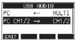
- Select PC CH1/2 → on the USB AUDIO Screen, and open the FROM PC CH1/2 Screen.
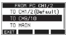
12 - USB audio interface functions
- Turn the MULTI JOG dial to select the assignment for the audio sent from computer USB channels 1–2.
| Option Meaning | |
| TO CH1/2 (default) | Audio sent from computer USB channels 1–2 will be input on mixer channels 1–2 of this unit (USB return channel function not used). |
| TO CH9/10 | Audio sent from computer USB channels 1–2 will be input on mixer channels 9/10 of this unit. This is a useful setting when using mic input on mixer channels 1–2 of this unit while adjusting audio from the computer when streaming, for example. |
| TO MAIN | Audio sent from computer USB channels 1–2 will be mixed on the MAIN MIX L/R bus of this unit's mixer.With this setting, when using this unit as audio interface input in DAW control mode, all analog inputs for mixer channels 1–10 of this unit can be sent to the DAW while monitoring the playback sound from the DAW. |
When a setting other than "TO CH1/2" is selected, sound will not be input from the computer to channels 1–2 of the mixer of this unit.
- Press the MULTI JOG dial to confirm the setting. The USB AUDIO Screen will reopen.
- When using the USB return channel function, the USB icons shown on the Home Screen when connected by USB will be different.
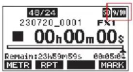
| Indicator appearance | Meaning |
| “TO CH1/2” selected (USB return channel function not used) | |
| 9/10 | “TO CH9/10” selected |
| Natin | “TO MAIN” selected |
- An DLY icon appears on the Home Screen when the OUTPUT DELAY function is used. The USB icon will not be shown.
Setting procedures for use with OBS Studio and other streaming applications
Conduct the procedures in this document before launching the streaming application.
Model 12 unit settings
- Set the MODEL 12 USB audio mode to STEREO MIX. (see "Setting the USB audio mode" on page 71)
- Turn the POST REC switch on to enable the MAIN fader for streamed audio. (see "Analog output adjustment section" on page 24)
- For Macs, the above settings make use with streaming applications possible.
Windows computer sound settings
Set the input and output device, sampling frequency, bit rate, and number of channels according to the setup.
- Open the Sound Settings screen.
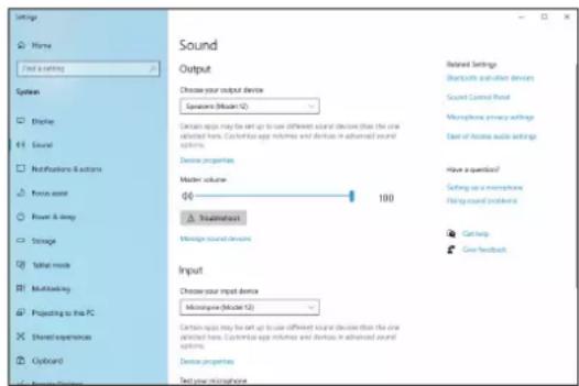
NOTE
This can also be opened by right-clicking the sound icon at the bottom right of the desktop screen, selecting "Open Sound settings" and then selecting "Sound".
12 - USB audio interface functions
- Set the output device to "Speakers (Model 12)".
- Set the input device to "Microphone (Model 12)".
- Click "Sound Control Panel" to open the Sound window.
- Open the Recording tab, and select "Model 12".
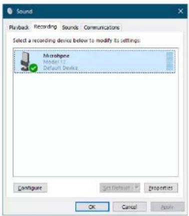
- Click "Properties" for "Model 12" to open the Microphone Properties screen.
- Open the Advanced tab, and set the Default Format.
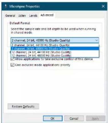
- Select a 2-channel setting when using OBS Studio or another application that supports 2-channel audio devices. Otherwise, select a 12-channel setting.
-
Select the sample rate according to the sample rate of the song loaded in the unit. Any sample rate can be used when not loading a song.
-
Open the Playback tab, and select "Speakers (Model 12)".
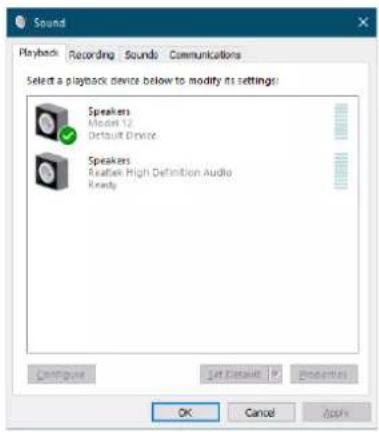
- Click "Properties" for "Speakers (Model 12)" to open the Speakers Properties screen.
- Open the Advanced tab, and set the Default Format. Set the sample rate and bit depth for the Default Device on the Play tab to the same values set on the Record tab.
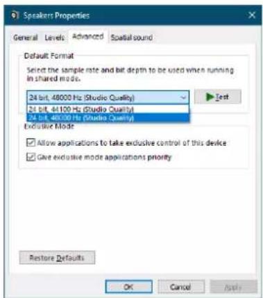
- Launch the streaming application, and proceed with streaming and other functions.
-
After completing streaming, restore the settings to multichannel to use multiple channels with other applications as necessary.
-
In step 1, set the USB audio mode to MULTI INPUT.
• In step 7, set the Microphone Properties to 12-channel.
13 - OUTPUT DELAY function
During live Internet streaming, when capturing audio with a different device from the camera video, lags could occur between the streamed video and audio.
If the video is behind the audio, an offset delay can be added intentionally to audio from the Model 12 USB output to correct the lag between the video and audio.
- When the recorder is stopped, select OUTPUT DELAY on the SYSTEM Screen, and open the OUTPUT DELAY Screen. (see "Menu operation procedures" on page 29)
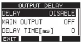
- Select DELAY on the OUTPUT DELAY Screen, and open the DELAY Screen.
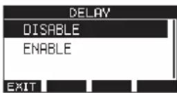
- Turn the MULTI JOG dial to enable/disable the OUTPUT DELAY function that applies delay to USB audio.
| Option Meaning | |
| DISABLE (default) Do not use the OUTPUT DELAY function | |
| ENABLE Use the OUTPUT DELAY function | |
- Press the MULTI JOG dial to confirm the setting. The OUTPUT DELAY Screen reopens.
- Press the F1 ENHT to return to the SYSTEM Screen.
NOTE
An DLY on appears on the Home Screen when the OUTPUT DELAY function is on (set to ENABLE).
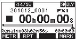
Using the OUTPUT DELAY function on signals output from the MAIN OUTPUT jacks
By selecting "ON" on the MAIN OUTPUT screen, the delay can be applied not only to the USB audio, but also to signals output from the MAIN OUTPUT jacks. This is useful when inputting audio for live streaming into a hardware encoder, video switcher or other external device. Furthermore, when the MAIN OUTPUT screen setting is "ON", the delayed sound can also be monitored by headphones. This allows the lag between the video and audio to be adjusted while watching the video and listening in real time.
-
When the recorder is stopped, select OUTPUT DELAY on the SYSTEM Screen, and open the OUTPUT DELAY Screen. (see "Menu operation procedures" on page 29)
-
Select MAIN OUTPUT on the OUTPUT DELAY Screen, and open the MAIN OUTPUT Screen.
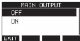
- Turn the MULTI JOG dial to set whether or not delay is applied to signals output from the MAIN OUTPUT jacks.
| Option Meaning | |
| OFF (default) | Do not use the OUTPUT DELAY function on signals output from the MAIN OUTPUT jacks |
| ON | Use the OUTPUT DELAY function on signals output from the MAIN OUTPUT jacks |
ATTENTION
- Even if the MAIN OUTPUT screen setting is "ON", if the DELAY screen setting is "DISABLE", delay will not be applied to signals output from the MAIN OUTPUT jacks.
-
Even if the DELAY screen setting is "ENABLE", when the USB audio mode setting is "MULTI INPUT", delay will not be applied to multichannel USB audio output (USB channels 1-10). However, delay will still be applied to signals output from the MAIN OUTPUT jacks if the MAIN OUTPUT screen setting is "ON".
-
Press the MULTI JOG dial to confirm the setting. The OUTPUT DELAY Screen will reopen.
- Press the F1 📋 to return to the SYSTEM Screen.
Setting the delay time of the OUTPUT DELAY function
- When the recorder is stopped, select OUTPUT DELAY on the SYSTEM Screen, and open the OUTPUT DELAY Screen.
- Select DELAY TIME on the OUTPUT DELAY Screen, and open the DELAY TIME Screen.
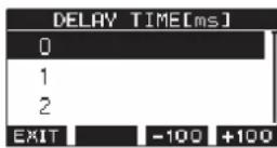
- Turn the MULTI JOG dial to set the delay time. Setting range: 0 (default) – 2000 (in 1 ms steps)
NOTE
The F3 -102F4 butt+100 range the delay time in 100ms steps rather than in 1ms steps. They do not decrease/increase the delay time -100/+100 ms.
- Press the MULTI JOG dial to confirm the setting. The OUTPUT DELAY Screen will reopen.
- Press the F1 2000 to return to the SYSTEM Screen.
14 - MIDI Implementation Chart
MIDI Implementation Chart
| Function Transmit Recognize Remarks | ||||
| Basic channels | When power on | × | × | Thru |
| Settable | × | × | ||
| Mode | When power on | × | × | Thru |
| Messages | × | × | ||
| Altered ...... | ||||
| Note number Range | × | × | Thru | |
| Velocity | Note on | × | × | Thru |
| Note off | × | × | ||
| Aftertouch | Polyphonic | × | × | Thru |
| Channel | × | × | ||
| Pitch bend | × | × | Thru | |
| Control change | × | × | Thru | |
| Program change | × | × | Thru | |
| Setting range ...... | ||||
| System exclusive | ○*1 | × | Thru | |
| System common | Position | ○*3 | × | Thru |
| Song select | × | × | ||
| Quarter frame | ○*2 | × | ||
| Tune | × | × | ||
| System real-time | Clock | ○*3 | × | Thru |
| Command | × | × | ||
| Other | Local on/off | × | × | Thru |
| All notes off | × | × | ||
| Active sense | × | × | ||
| Reset | × | × | ||
| Notes*1 MTC full message when MIDI TIME CODE is ON*2 When MIDI TIME CODE is ON*3 When MIDI CLOCK/SPP is ON | ||||
Mode 1: OMNI ON, POLY Mode 2: OMNI ON, MONO O: YES
Mode 3: OMNI OFF, POLY Mode 4: OMNI OFF, MONO X: NO
15 - Messages
The following is a list of messages that appear in pop-up windows.
Refer to this list if one of these pop-up messages appears on the Model 12 and you want to check the meaning or determine a proper response.
| Message Meaning and response | |
| Card Error The SD card cannot be recognized properly. Replace the SD card. | |
| Card Full The SD card has no remaining capacity. | |
| Dup File Name A file with the same name already exists. Change the file name. | |
| File Not Found The file cannot be found or the file may be damaged. Check the relevant file. | |
| No sys fileMake sys file | The system file is missing. This unit requires a system file for operation.When this message appears, press the MULTI JOG dial to create a system file. |
| Song Protected This operation is not possible because the song is protected. Remove protection. | |
| Invalid CardChange Card | Something might be wrong with the SD card. Change the SD card. |
| I/O Too Short | On the AUTO PUNCH Screen, the time between the punch in and out points is too short. Set them with at least 1 second between them.On the VAMP Editing Screen, the time between the VAMP in and out points is too short. Set them with at least 2 second between them. |
| MBR errorInit card | The SD card is not formatted properly or the card is broken.Change the SD card or press the MULTI JOG dial while this message is being shown to format the card. Formatting will erase all the data on the SD card. |
| No Card | A SD card is not set.Insert a recordable SD card. |
| Non-supported | The file format is not supported. Please see “Playing WAV files on SD cards (SD PLAY mode)” on page 64 for file formats that this unit can use. |
| Card Protected The SD card is write-protected. Disable SD card write-protection. | |
| USB Fs mismatch | The sampling rate of the current song and the USB audio interface are not the same.Change the sampling rate of one so that they are the same. |
| Current Song The current song cannot be deleted. To delete the current song, load another song first. | |
| Invalid I/O point | The punch in/out point settings on the AUTO PUNCH Screen are not set correctly.Automatic punching in/out occurred at an invalid position for the punch in or out point.Start the automatic punch operation from a valid point.The VAMP in/out point settings on the VAMP Editing Screen are not set correctly.Change the position of the VAMP in or out point. |
| Write errorREC continue | Writing to the SD card timed out. This has caused audio to be interrupted and noise to occur. |
| REC stopCard slow | Writing to the SD card timed out, and recording stopped.SD card writing performance has become worse.Execute the erase format function or change the SD card. |
| Need to set I/O point. | Neither the punch in or out points are set for the automatic punch in/out function.Either the punch in or out point must be set. |
| Sample rateUnmatch | The sampling frequency of the WAV file to be imported does not match the current song.Select a WAV file with the same sampling frequency as the current song or convert the sampling frequency before importing. |
| Remain time is not enough | The SD card does not have enough open space, so importing is not possible.Erase unnecessary files or transfer them to a computer. |
| 8 trackpunch in limit | The maximum number of tracks for punch in recording is eight.Press REC buttons to reduce the number of recording tracks to eight or less. |
| Song is not loaded | No song is loaded.Create a new song or load a song. |
| Song number full | The maximum number of songs that can be created on an SD card is 100.Erase unnecessary songs. |
| SD PLAY: cannot record | SD PLAY mode is for playback only.Recording is not possible. |
| SD CARD cluster size error | Recording is not possible because the SD card cluster size is not right.Back up the contents of the SD card on a computer and then format it with this unit.Then, restore the data from the computer. |
| Import error.No track | Importing is not possible because there are no open tracks.Use TRACK CLEAR to clear a track. (see “Clearing tracks” on page 46) |
| Message Meaning and response | |
| Invalid track | The selected track cannot be used for replacement.Change the track selection on the TRACK SWAP screen. (see “Swapping tracks” on page 47) |
| Already protected The selected song is already protected. | |
| Already unprotected The selected song is already unprotected. | |
| VAMP MODE: cannot record | Recording is not possible when the VAMP Playback Screen or VAMP Editing Screen is open. Turn the VAMP playback function off to record. |
| VAMP MODE:A.PUNCH disabled | The auto punch in/out function cannot be set when the VAMP Playback Screen is open.Turn the VAMP playback function off to set the auto punch in/out function. |
| VAMP full | A maximum of 10 VAMP in/out points can be set in a single song.Clear unneeded VAMP in/out points. |
| Can’t Save Data | If any of these errors occurs, turn the unit off and restart it.If these error messages continue to appear frequently, please contact the store where you purchased this unit or TASCAM customer support. |
| Device Error | |
| File Error | |
| Not Continued | |
| Player Error | |
| UNDO not available | |
| Writing Failed | |
| Sys Rom Err | |
| System Err XX(XX is a number.) | |
16 - Troubleshooting
If you are having trouble with the operation of this unit, please try the following before seeking repair.
If these measures do not solve the problem, please contact the store where you bought the unit or TASCAM customer support service.
The unit will not turn on
- Confirm that the power plug and other connectors are inserted completely.
The SD card is not recognized
- Confirm that the SD card is inserted completely.
No sound is output
- Are the input sources and MODE switches set properly?
- Are that channel faders raised to suitable levels?
- Is the MAIN fader raised to a suitable level?
- Is a monitoring system correctly connected to the PHONES jack or SUB OUTPUT jacks?
Is the monitoring system set up correctly?
- Is the PHONES knob or SUB fader place to a suitable level?
- Is the SD MAIN MIX RETURN switch on (pushed in, during playback of anything other than a stereo master file)?
- Are the SOLO or AFL switches on for each channel?
The sound I want to record is distorted
- Are the channel GAIN knobs set too high?
Are the input source levels to high? - Is the EQ set too high?
- Are any channel faders or the MAIN fader raised too high?
- Is the monitoring level too high, causing the monitoringsystem to distort?
Noise occurs when a passive guitar or bass is connected directly
- Connecting another device to the unit's SUB OUTPUT jacks (stereo output) could reduce noise.
- It could be affected by interference noise from another device, for example. If a power amplifier or other device with a large transformer, or a fluorescent light, for example, is nearby, changing the distance or orientation of such devices could reduce noise.
Playback is not possible
- If you are trying to play a WAV file, confirm that it uses a sampling frequency (44.1/48 kHz) and a bit depth (16/24-bit) that are supported by this unit.
There is noise
- Confirm that the connection cables do not have contact issues.
Sound via Bluetooth breaks up or is noisy
- Are there any wireless LAN devices, other Bluetooth devices, microwave ovens or similar equipment nearby? Keep such devices as far away as possible during use.
- Try reducing the distance between this unit and the other Bluetooth device. Try changing the positions of this unit and the other Bluetooth device.
- The operation of apps other than for music playback on the smartphone could cause the sound to break up. In this case, stop operation of apps other than the one used for music playback.
Cannot connect or communication is interrupted when using Bluetooth
- Confirm that the other Bluetooth device power is on and that its Bluetooth function is on.
- Confirm that the other Bluetooth device is not too far away. Are there walls or other obstacles, for example, between this unit and the other Bluetooth device?
Try changing the positions of this unit and the other Bluetooth device.
- Turn OFF and restart the Model 12.
- pp Remove the "Model 12" pairing record from the other Bluetooth device, and try pairing the unit with that Bluetooth device again. (see "Connecting with Bluetooth devices" on page 32)
Cannot pair with another Bluetooth device
- Confirm that the other Bluetooth device supports A2DP.
- Confirm that the other Bluetooth device is in a state that allows transmission. For details, check the operation manual of that Bluetooth device.
- Turn the power off for both this unit and the other Bluetooth device once, turn them both on again and try pairing them.
- Turn off Bluetooth devices other than the one that you are trying to pair with.
- Remove the "Model 12" pairing record from the other Bluetooth device, and try pairing the unit with that Bluetooth device again. (see "Connecting with Bluetooth devices" on page 32)
A computer does not recognize the unit when connected by USB
- Has the dedicated software been installed? (see "Installing the dedicated software" on page 67)
- This unit cannot be used with USB 1.1. Use a USB 2.0 or USB 3.0 port.
- Do not use a USB hub with this unit. Always connect the unit directly to a USB port on the computer.
- If the above methods do not resolve the problem, connect the unit to a different USB port on the computer.
When connected by USB, sound breaks up or noise occurs.
● The processing load on the computer causes sound to break up and noise to occur.
- If a wireless LAN or background software, including antivirus software, is running, turn it off during use of this unit. In addition, please use "computer's power option" as "high performance setting".
- Use the shortest USB cable possible.
- Use a USB port built into the computer because the computer USB port affects the USB connection.
General
Supported media
SD cards (Class 10 or more)
SDHC cards (Class 10 or more)
SDXC cards (Class 10 or more)
File System
SD card: FAT16
SDHC card: FAT32
SDXC card: exFAT
Recording file formats
WAV (BWF): 44.1/48kHz, 16/24-bit (Maximum file size: 2 GB)
Playback file formats
WAV (BWF): 44.1/48kHz, 16/24-bit
Recordable Channel
Max. 12 channels (10ch + 2 stereo mix)
Inputs and outputs
Analog audio input and output ratings
MIC input jacks (1-6, 7, 9)
Connectors: XLR-3-31 (1: GND, 2: HOT, 3: COLD)
Maximum input level: +10 dBu
Nominal input level: -8 dBu
Minimum input level: -58 dBu
Gain adjustment range: 0 - 50 dB
Input impedance: 1.8 kΩ
LINE (BAL)/INST input jacks (1-6)
Connectors: 6.3mm (1/4") standard TRS jacks
(Tip: HOT, Ring: COLD, Sleeve: GND)
Maximum input level: +22 dBu (LINE)/19.8 dBV (INST)
Nominal input level: +4 dBu (LINE)/ 1.8 dBV (INST)
Gain adjustment range: -10 - +40 dB
Input impedance: 22 kΩ (LINE)/1 MΩ (INST)
L/MONO(BAL)/INST input jacks (7, 9)
Connectors: 6.3mm (1/4") standard TRS jacks
(Tip: HOT, Ring: COLD, Sleeve: GND)
Maximum input level: +22 dBu (LINE)/19.8 dBV (INST)
Nominal input level: +4 dBu (LINE)/ 1.8 dBV (INST)
Gain adjustment range: -20 - +30 dB
Input impedance: 18 kΩ (LINE)/ 1 MΩ (INST)
R (BAL) input jacks (8, 10)
Connectors: 6.3mm (1/4") standard TRS jacks
(Tip: HOT, Ring: COLD, Sleeve: GND)
Maximum input level: +22 dBu
Nominal input level: +4 dBu
Gain adjustment range: -20 - +30 dB
Input impedance: 18 kΩ
INSERT jacks (1-2)
Connectors: 6.3mm (1/4") standard TRS jacks
(Tip: SEND, Ring: RETURN, Sleeve: GND)
RETURN (Ring)
Maximum input level: +18 dBu
Nominal input level: 0 dBu
Input impedance: 5 kΩ
SEND (Tip)
Maximum output level: +18 dBu
Nominal output level: 0 dBu
Output impedance: 100 Ω
MUSIC/TALK jack (9/10)
Connector: 3.5mm (1/8") 4-pole mini jack
(Tip: L, Ring1: R, Ring2: GND, Sleeve: MIC)
Maximum input level: +8 dBV
Nominal input level: -10 dBV
Input impedance: 10 kΩ
MAIN OUTPUT L/R jacks
Connectors: XLR-3-32 (1: GND, 2: HOT, 3: COLD)
Maximum output level: +22 dBu
Nominal output level: +4 dBu
Output impedance: 200 Ω
SUB OUTPUT L/R jacks
Connectors: 6.3mm (1/4") standard TRS jacks (Tip: HOT, Ring:
COLD, Sleeve: GND)
Maximum output level: +16 dBu
Nominal output level: -2 dBu
Output impedance: 200 Ω
AUX OUTPUT AUX 1/2 jacks
Connectors: 6.3mm (1/4") standard TRS jacks (Tip: HOT, Ring:
COLD, Sleeve: GND)
Maximum output level: +16 dBu
Nominal output level: -2 dBu
Output impedance: 200 Ω
PHONES jack
Connector: 6.3mm (1/4") standard stereo jack
Maximum output: 45mW + 45mW (32Ω load)
Control input/output
USB port
Connector: 4-pin USB C-type
Protocol: USB 2.0 HIGH SPEED (480 Mbps)
CLICK jack
Connector: 6.3mm (1/4") standard TS jacks
(Tip: HOT, Sleeve: GND)
FOOTSWITCH jack
Connector: 6.3mm (1/4") standard TRS jacks
(Tip: FOOTSW1, Ring: FOOTSW2,Sleeve: GND,
Unlatch type correspondence)
MIDI OUT connector
Connector: 5-pin DIN
Format: standard MIDI
17 - Specifications
MIDI IN connector
Connector: 5-pin DIN
Format: standard MIDI
Computer system requirements
Check the TEAC Global Site (https://teac-global.com/) for the latest information about supported operating systems.
Windows
Supported operating systems
Windows 10 32-bit
Windows 10 64-bit
Windows 8.1 32-bit
Windows 8.1 64-bit
Windows 7*
Windows 7 32-bit SP1 or later
Windows 7 64-bit SP1 or later
* Operation has been confirmed with the final version of Windows 7.
Computer hardware requirements
Windows computer with a USB 2.0 (or higher) port
CPU/processor speed
2 GHz or faster dual core processor (x86)
Memory
2 GB or more
ATTENTION
Operation of this unit was confirmed using standard computers that meet the above requirements. This does not guarantee operation with all computers that meet the above requirements. Even computers that meet the same system requirements might have processing capabilities that differ according to their settings and other operating conditions.
Mac
Supported operating systems
macOS Catalina (10.15)
macOS Mojave (10.14 or later)
macOS High Sierra (10.13 or later)
Computer hardware requirements
Mac with a USB 2.0 (or higher) port
CPU/processor speed
2 GHz or faster dual core processor
Memory
2 GB or more
iOS device
Operation has been confirmed with Apple devices running the following iOS versions.
iPadOS13
iOS13
iOS12
iOS11
ATTENTION
To connect an iOS device that has a Lightning connector, a genuine Apple Lightning to USB Camera Adapter (sold separately) is necessary.
Supported audio drivers
Windows
ASIO2.0, WDM
Mac
Core Audio
iOS divice
Core Audio
Audio performance
S/N ratio
103dB (MAIN MIX & 1Ch 0dB, 22kHz, A-weighted)
Equivalent input noise (EIN)
-128 dBu (Rs=150 Ω, MIC IN → INSERT SEND, gain knob at MAX, A-weighted)
Total harmonic distortion ratio (THD+N)
0.003% (MONO MIC IN → MAIN OUT, +2dBu, 1kHz, gain knob at MIN)
Frequency response
20Hz to 20kHz (+0.3/-0.7 dB, 1kHz, MIC IN → MAIN OUT)
Crosstalk
(PAN knobs turned completely left or right, 1 kHz)
Between channels: -95 dB
Between input and output: -95 dB
Maximum gain
(All GAIN knobs maximized, PAN knobs turned completely left or right, EQ knobs and MASTER SECTION EQ knobs at middle positions)
MIC → MAIN OUT: 74 dB
MIC → INSERT OUT: 54 dB
MIC → SUB OUT: 74 dB
MIC → AUX OUT: 75 dB
USB/SD → MAIN OUT: 24 dB
Bluetooth
Bluetooth version: 5.1
Output class: 2 (about 10m^# unobstructed transmission distance)
Supported profile: A2DP
Supported A2DP codecs: SBC, AAC
Supported A2DP content protection: SCMS-T
* The transmission distance is only an estimate and might vary depending on the surrounding environment and radio wave conditions.
Other
Power
Dedicated AC adapter (PS-M1524)
Input voltage: AC 100–240V \~, 50/60Hz
Output voltage: DC 15V ---
Output current: 2.4 A
Power consumption
16W
Dimensions
With side panels
343.0 × 98.8 × 360.0 mm (W x H x D, including protrusions)
Without side panels
315.0 × 98.8 × 360.0 mm (W x H x D, including protrusions)
Weight
4.3kg
Operating temperature range
5 - 35°C (41 - 95°F)
● Illustrations in this manual might differ in part from the actual product.
- pp Specifications and external appearance might be changed without notification to improve the product.
17 - Specifications
INSTRUCTIONS DE SÉCURITÉ IMPORTANTES ....7
Performances audio....150
Bluetooth....151
Autres....151
https://teac-global.com/
⑲ Prise PHONES (1/2)
④0 Bouton PFL/AFL MASTER
- Bus MAIN MIX L/R
- Bus SOLO L/R
- Bus AUX1
- Bus SUB L/R
④9 Bouton TO AUX 1
- Bus MAIN MIX L/R
- Bus SOLO L/R
- Bus AUX1
- Bus SUB L/R
⑥0 Prises MAIN OUTPUT L/R
- 3 points (TRS, pointe = point chaud, bague = point froid et manchon = masse)
- 3 points (TRS, pointe = point chaud, bague = point froid et manchon = masse)
- Jack TRS 3 points (pointe = FOOTSW1, bague = FOOTSW2 et manchon = masse)
NOTE
48/15 48 kHz, 16 bit
48/24 48 kHz, 24 bit
NOTE
- Bus MAIN MIX L/R
- Bus SOLO L/R
- Bus AUX1
- Bus SUB L/R
ATTENTION
NOTE
WAV: 44,1/48 kHz, 16/24 bit
BWF : 44,1/48 kHz, 16/24 bit
NOTE
Écran de Windows 10
NOTE
NOTE
Mode 1 : OMNI ON, POLY Mode 2 : OMNI ON, MONO O : OUI
Mode 3: OMNI OFF, POLY Mode 4: OMNI OFF, MONO X: NON
15 - Messages
WAV (BWF): 44,1/48 kHz, 16/24 bit
WAV/BWF : 44,1/48 kHz, 16/24 bit
Prises MAIN OUTPUT L/R
Prises SUB OUTPUT L/R
https://teac-global.com/
④ Interruptores MODE (1-6, 7/8-9/10)
②3 Interruptor EQ IN/BYPASS
③5 Interruptor/indicador MUTE (AUX 1/AUX 2)
③6 Interruptores AFL (AUX 1/AUX 2)
④0 Mando PFL/AFL MASTER
④4 Interruptor e indicadores MUTE (FX)
- Bus MAIN MIX L/R
- Bus SOLO L/R
- Bus AUX1
- Bus SUB L/R
④9 Mandos TO MON 1
- Bus MAIN MIX L/R
- Bus SOLO L/R
- Bus AUX1
- Bus SUB L/R
⑤1 Interruptor MAIN (FX)
⑤2 Interruptor SUB (FX)
⑤3 Interruptor AFL (FX)
⑤5 Interruptor AUX 1 (FX)
⑤6 Interruptor MAIN (SUB)
- Bus MAIN MIX L/R
- Bus SOLO L/R
- Bus AUX1
- Bus SUB L/R
ATENCIÓN
- Pulse F1 Solveolver a la pantalla FOOTSW.
NOTA
WAV: 44.1/48 kHz, 16/24 bits
BWF: 44.1/48 kHz, 16/24 bits
NOTA
Uso del Gatekeeper
Si el ajuste de Gatekeeper es "Allow applications downloaded from: the Mac App Store"
Cuando aparezca el mensaje de advertencia "ModelMixer_ Installer.pkg' can't be opened because it was not downloaded from the Mac App Store. Are you sure you want to open it?", haga clic en el botón "Open".
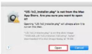
Cuando el ajuste del Gatekeeper no sea "Allow applications downloaded from: the Mac App Store"
② Buffer Size (solo Windows)
Pantalla Windows 10
NOTA
NOTA
Modo 1: OMNI ON, POLY Modo 2: OMNI ON, MONO O: SÍ
Modo 3: OMNI OFF, POLY Modo 4: OMNI OFF, MONO X: NO
15 - Mensajes
Conectores MAIN OUTPUT
Conectores: XLR-3-32 (1: masa, 2: activo, 3: pasivo)
Conector: 6.3 mm (1/4") standard stereo
Salida máxima: 45 mW + 45 mW (32 Ω de carga)
Entrada/salida de control
Puerto USB
20 Hz a 20 kHz (+0.3/-0.7 dB, 1 kHz, MIC IN → MAIN OUT)
MIC → MAIN OUT: 74 dB
MIC → INSERT OUT: 54 dB
MIC → SUB OUT: 74 dB
MIC → AUX OUT: 75 dB
USB/SD → MAIN OUT: 24 dB
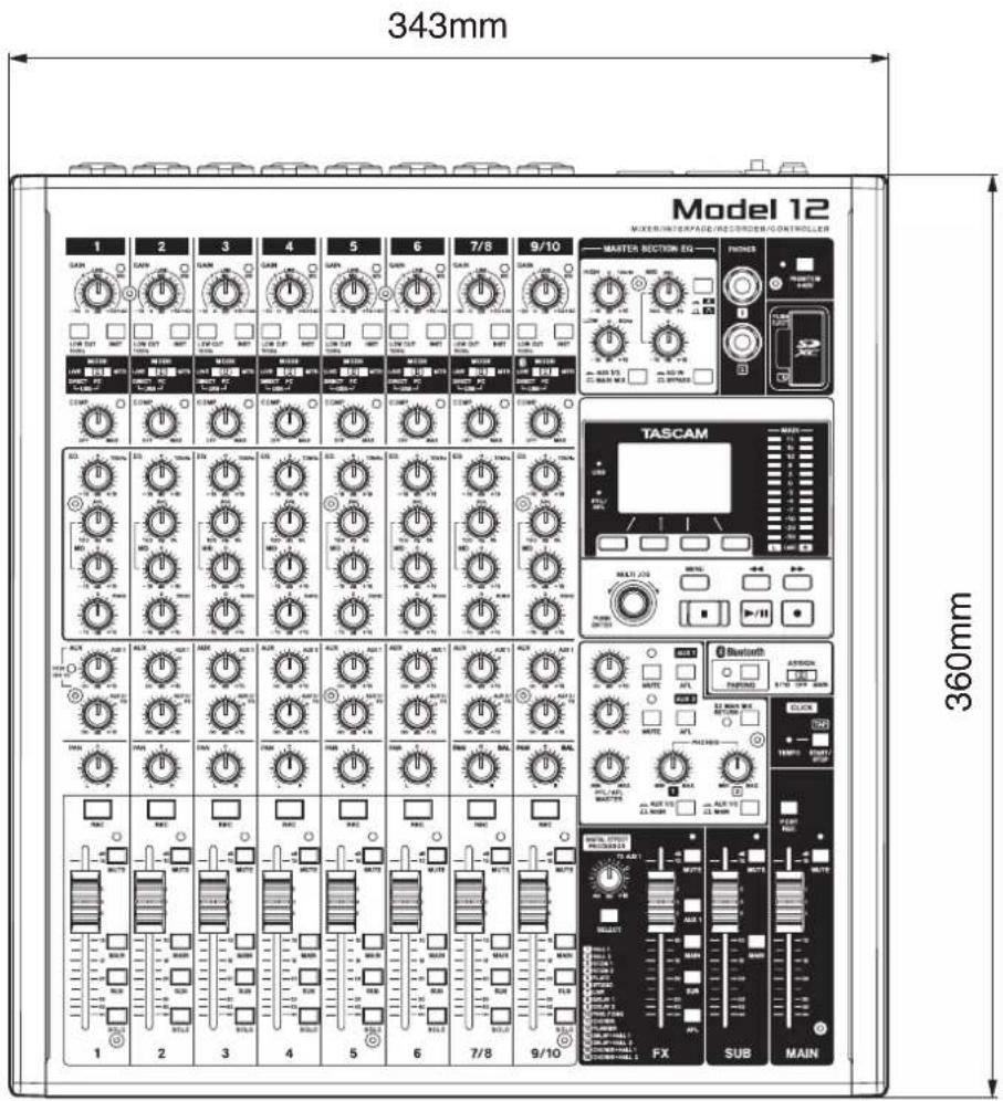
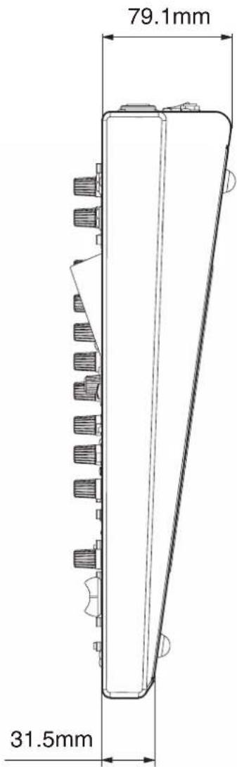
flowchart
graph TD
    subgraph_Input_Channel["Input channel MONO"]
        A["Input Channel MONO"] --> B["MC INPUT"]
        B --> C["LINE/Instrument INPUT"]
        C --> D["Channel Insert INPUT"]
        D --> E["MC INPUT"]
        E --> F["LINE/Instrument INPUT"]
        F --> G["Input Channel MONO"]
        G --> H["MC INPUT"]
        H --> I["Line/Instrument INPUT"]
        I --> J["Input Channel STEREO"]
        J --> K["MC INPUT"]
        K --> L["Line/Instrument (SAR)"]
        L --> M["Output Channel STEREO"]
        M --> N["MINI/STEREO"]
        N --> O["MUSIC/TALK (TRRS)"]
        O --> P["INPUT/L/MICOUT"]
        P --> Q["BLUETOOTH"]
    end

    subgraph_Input_Channel["Input Channel STEREO"]
        R["Input Channel STEREO"] --> S["MINI/STEREO"]
        T["Input Channel STEREO"] --> U["MINI/STEREO"]
        V["Input Channel STEREO"] --> W["MINI/STEREO"]

    end

    subgraph_Input_Channel["Input Channel STEREO"]
        X["Input Channel STEREO"] --> Y["MINI/STEREO"]
        Z["Input Channel STEREO"] --> AA["MINI/STEREO"]

    end

    subgraph_Input_Channel["Input Channel STEREO"]
        AB["Input Channel STEREO"] --> AC["MINI/STEREO"]

    subgraph_Input_Channel["Input Channel STEREO"]
        AD["Input Channel STEREO"] --> AE["MINI/STEREO"]

    subgraph_Input_Channel["Input Channel STEREO"]
        AF["Input Channel STEREO"] --> AG["MINI/STEREO"]

    subgraph_Input_Channel["Input Channel STEREO"]
        AH["Input Channel STEREO"] --> AI["MINI/STEREO"]

    subgraph_Input_Channel["Input Channel STEREO"]
        AJ["Input Channel STEREO"] --> AK["MINI/STEREO"]

    subgraph_Input_Channel["Input Channel STEREO"]
        AL["Input Channel STEREO"] --> AM["MINI/STEREO"]

    subgraph_Input_Channel["Input Channel STEREO"]
        AN["Input Channel STEREO"] --> AO["MINI/STEREO"]

    subgraph_Input_Channel["Input Channel STEREO"]
        AP["Input Channel STEREO"] --> AQ["MINI/STEREO"]

    subgraph_Input_Channel["Input Channel STEREO"]
        AR["Input Channel STEREO"] --> AS["MINI/STEREO"]

    subgraph_Input_Channel["Input Channel STEREO"]
        AT["Input Channel STEREO"] --> AU["MINI/STEREO"]

    subgraph_Input_Channel["Input Channel STEREO"]
        AV["Input Channel STEREO"] --> AW["MINI/STEREO"]

    subgraph_Input_Channel["Input Channel STEREO"]
        AX["Input Channel STEREO"] --> AY["MINI/STEREO"]

    subgraph_Input_Channel["Input Channel STEREO"]
        AZ["Input Channel STEREO"] --> BA["MINI/STEREO"]

    subgraph_Input_Channel["Input Channel STEREO"]
        BB["Input Channel STEREO"] --> BC["MINI/STEREO"]

    subgraph_Input_Channel["Input Channel STEREO"]
        BD["Input Channel STEREO"] --> BE["MINI/STEREO"]

    subgraph_Input_Channel["Input Channel STEREO"]
        BF["Input Channel STEREO"] --> BG["MINI/STEREO"]

    subgraph_Input_Channel["Input Channel STEREO"]
        BH["Input Channel STEREO"] --> BI["MINI/STEREO"]

    subgraph_Input_Channel["Input Channel STEREO"]
        BJ["Input Channel STEREO"] --> BK["MINI/STEREO"]

    subgraph_Input_Channel["Input Channel STEREO"]
        BL["MUSIC/TALK (TRRS)"] --> BM["MICOUT"]
        BN["MICOUT"] --> BO["MICOUT"]

    subgraph_Input_Channel["Input Channel STEREO"]
        BP["MUSIC/TALK (TRRS)"] --> BQ["MICOUT"]
        BR["MICOUT"] --> BS["MICOUT"]

    subgraph_Input_Channel["Input Channel STEREO"]
        BT["MUSIC/TALK (TRRS)"] --> BU["MICOUT"]
        BV["MICOUT"] --> BW["BuMOUT"]

    subgraph_Input_Channel["Input Channel STEREO"]
        BX["MUSIC/TALK (TRRS)"] --> BY["MICOUT"]
        BZ["MICOUT"] --> CA["MICOUT"]

    subgraph_Input_Channel["Input Channel STEREO"]
        CB["MUSIC/TALK (TRRS)"] --> CC["MICOUT"]
        DA["MICOUT"] --> DB["MICOUT"]

    subgraph_Input_Channel["Input Channel STEREO"]
        DC["MUSIC/TALK (TRRS)"] --> DD["MICOUT"]
        DE["MICOUT"] --> DF["MICOUT"]

    subgraph_Input_Channel["Input Channel STEREO"]
        DG["MUSIC/TALK (TRRS)"] --> DH["MICOUT"]
        DI["MICOUT"] --> DJ["MICOUT"]

    subgraph_Input_Channel["Input Channel STEREO"]
        DK["MUSIC/TALK (TRRS)"] --> DL["MICOUT"]
        DV["MICOUT"] --> DW["MICOUT"]

    subgraph_Input_Channel["Input Channel STEREO"]
        DX["MUSIC/TALK (TRRS)"] --> DXM["MICOUT"]
        DXM --> DXN["MICOUT"]

    subgraph_Input_Channel["Input Channel STEREO"]
        DXM --> DXN

    end

    subgraph_Input_Channel["Input Channel STEREO"]
        DXN --> DXN

    end

    style Input_Channel fill:#f9f,stroke:#333
    style Output_Channel fill:#ccf,stroke:#333
Level diagram / Schéma des niveaux / Diagrama de niveles
Model 12 LEVEL DIAGRAM
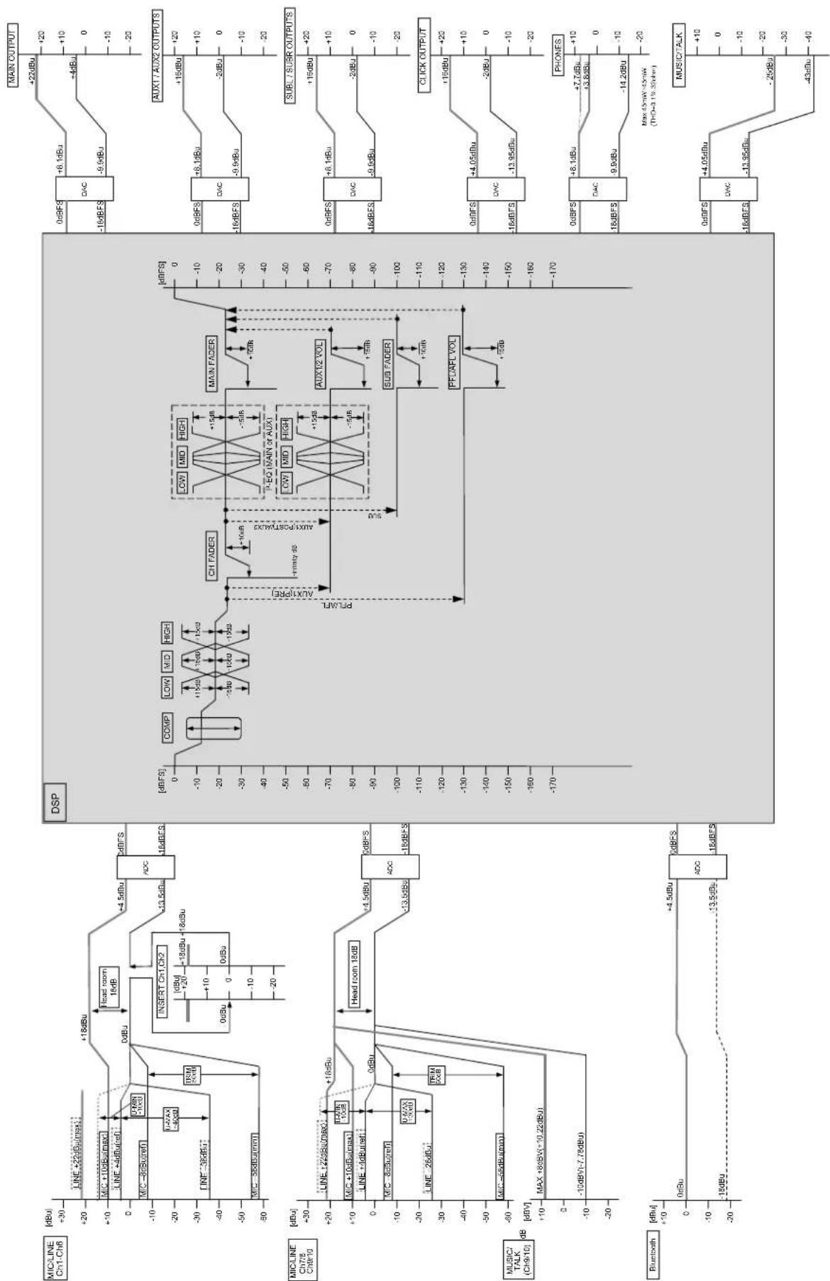
WARRANTY
This warranty gives you specific legal rights and you may also have other rights which vary from state to state. This warranty is only valid within the country the unit was originally purchased.
WHAT IS COVERED AND WHAT IS NOT COVERED Except as specified below, this warranty covers all defects in materials and workmanship in this product. The following are not covered by the warranty:
- Damage to or deterioration of the external cabinet.
- Damage resulting from accident, misuse, abuse or neglect.
- Damage resulting from failure to perform basic daily maintenance and/or calibration or otherwise resulting from failure to follow instructions contained in your owner's manual.
- Damage occurring during shipment of the product. (Claims must be presented to the carrier)
- Damage resulting from repair or attempted repair by anyone other than TEAC or an authorized TASCAM service station.
- Damage resulting from causes other than product defects, including lack of technical skill, competence, or experience of the user.
- Damage to any unit which has been altered or on which the serial number has been defaced, modified or is missing.
WHO IS COVERED UNDER THE WARRANTY
This warranty may be enforced only by the original purchaser. This warranty is not valid if the product was purchased through an unauthorized dealer.
LENGTH OF WARRANTY
All parts except heads and disk drives are warranted for one (1) year from the date of original purchase. Heads and disk drives are warranted for ninety (90) days from date of original purchase. Labor is warranted for ninety (90) days from date of original purchase.
WHAT WE WILL PAY FOR
We will pay all labor and material expenses for items covered by the
warranty. Payment of shipping charges is discussed in the next section of this warranty.
HOW YOU CAN GET WARRANTY SERVICE
Your unit must be serviced by an authorized TASCAM service station in the United States. (This warranty is not enforceable outside the U.S.) If you are unable to locate an authorized TASCAM service station in your area, please contact us. We either will refer you to an authorized service station or instruct you to return the unit to the factory. Whenever warranty service is required, you must present a copy of the original dated sales receipt from an Authorized TASCAM Dealer.
You must pay any shipping charges if it is necessary to ship the product to service. However, if the necessary repairs are covered by the warranty, we will pay return surface shipping charges to any destination within the United States.
LIMITATION OF IMPLIED WARRANTIES
Any implied warranties, INCLUDING WARRANTIES OF MERCHANTABILITY AND FITNESS FOR A PARTICULAR PURPOSE, are limited in duration to the length of this warranty.
EXCLUSION OF DAMAGES
TEAC's liability for any defective product is limited to repair or replacement of the product, at TEAC's option. TEAC shall not be liable for:
-
Damages based upon inconvenience, loss of use of the product, loss of time interrupted operation or commercial loss; or
-
Any other damages, whether incidental, consequential or otherwise.
Some states do not allow limitations on how long an implied warranty lasts and/or do not allow the exclusion or limitation of incidental or consequential damages, so the above limitations and exclusions may not apply to you.
To locate an Authorized Service Center in Your Area
CALL 1-323-726-0303
This product is subject to the legal warranty regulations of the country of purchase. In case of a defect or a problem, please contact the dealer where you bought the product.
This warranty gives you specific legal rights, and you may also have other rights that vary by country, state or province.
If you have a warranty claim or request, please contact the dealer where you bought the product.
If you require repair services for your TASCAM equipment, please contact the dealer where the product was purchased from or the TASCAM Distributor in your country. A list of TASCAM Distributors can be found on our website at: https://teac-global.com/
TASCAM
TEAC CORPORATION https://tascam.jp/jp/
Phone: +81-42-356-9143
1-47 Ochiai, Tama-shi, Tokyo 206-8530 Japan
TEAC AMERICA, INC. https://tascam.com/us/
Phone: +1-323-726-0303
10410 Pioneer Blvd., Unit #1, Santa Fe Springs, California 90670, U.S.A
TEAC UK Ltd. https://www.tascam.eu/en/
Phone: +44-1923-797205
Luminous House, 300 South Row, Milton Keynes, Buckinghamshire, MK9 2FR, United Kingdom
TEAC EUROPE GmbH https://www.tascam.eu/de/
Phone: +49-611-71580
Room 817, Xinian Center A, Tairan Nine Road West, Shennan Road, Futian District, Shenzhen, Guangdong Province 518040, China
Printed in China 1123.MA-3091F
WARRANTY
https://teac-global.com/
Deal address / Adresse du revendeur / Adress des Händlers

- ASIO
- COMPATIBLE
- IMPORTANT SAFETY INSTRUCTIONS
- For U.S.A.
- Supplier's Declaration of Conformity
- INFORMATION TO THE USER
- CAUTION
- For Canada
- WARNING
- For European Customers
- Disposal of electrical and electronic equipment and batteries and/or accumulators
- For China
- Compliance of radio transmitter and interference
- Model for USA
- Model for Canada
- Model for EEA (European Economic Area)
- Radiation Exposure requirements
- Statement of compliance
- Model for USA/Canada
- INSTRUCTIONS DE SÉCURITÉ IMPORTANTES
- Pour le Canada
- IMPORTANT SAFETY INSTRUCTIONS .... 3
- Wireless equipment precautions 5
- - Introduction......17
- - Names and Functions of Parts 20
- - Preparation 30
- - Managing Songs....35
- - Basic recording 39
- - Recorder functions 43
- - Track editing 46
- - Mark functions....50
- Contents
- - Other functions....51
- - Settings and Information....62
- - Using a computer to transfer data 65
- - USB audio interface functions....67
- - OUTPUT DELAY function....74
- - MIDI Implementation Chart....75
- - Messages....76
- - Troubleshooting 78
- - Specifications....79
- Features
- Items included with this product
- ATTENTION
- Conventions used in this manual
- TIP
- NOTE
- - Introduction
- Precautions for placement and use
- Beware of condensation
- Cleaning the unit
- About SD cards
- Precautions for use
- SD card write protection
- Note about formatting
- Bluetooth®
- Profiles
- Codecs
- Content protection
- Transmission security
- Using the TEAC Global Site
- About TASCAM customer support service
- - Names and Functions of Parts
- Top panel
- Input channel mixing section-1
- Input channel mixing section-2
- Equalizer section
- ⑰ MASTER SECTION EQ knobs
- ⑱ switch
- ⑲ PHONES jack (1/2)
- ⑳ PHANTOM +48V switch and indicator
- ②1 SD card slot
- ② AUX 1/2/MAIN MIX switch
- ⑳ EQ IN/BYPASS switch
- Screen operation section
- ⑳ Display
- ⑲ USB indicator
- ②6 PFL/AFL indicator
- ⑳ Function buttons
- ⑳ MULTI JOG dial
- Dial functions
- Button function
- ⑲ Output level indicators
- ③0 ◀◀/▶▶ buttons
- ③1 MENU button
- ③2 ■ button/indicator
- ③3 ▶ /II button/indicator
- ③4 ● button/indicator
- Monitoring section
- ③5 MUTE switch/indicator (AUX 1/AUX 2)
- ③6 AFL switches (AUX 1/AUX 2)
- ③7 PAIRING button and indicator
- ③8 ASSIGN switch
- ⑲ AUX 1/AUX 2 knobs
- ④0 PFL/AFL MASTER knob
- ④1 SD MAIN MIX RETURN switch
- ④2 PHONES knob (1/2)
- ④3 AUX 1/2 /MAIN switch
- Analog output adjustment section
- ④4 MUTE switch and indicator (FX)
- ④5 MUTE switches and indicators (SUB, MAIN)
- ④6 TEMPO indicator
- ④7 CLICK button
- ④8 FX fader
- ④9 TO AUX 1 knob
- ⑤0 SELECT button
- ⑤1 MAIN switch (FX)
- ⑤2 SUB switch (FX)
- ⑤3 AFL switch (FX)
- ⑤4 POST REC switch
- ⑤⁵ AUX 1 switch (FX)
- ⑤6 MAIN switch (SUB)
- ⑤7 SUB fader
- ⑤8 MAINfader
- Rear panel
- ⑤9 USB port
- ⑥0 MAIN OUTPUT L/R jacks
- ⑥2 MIC/LINE (BAL)/INST input jacks (7/8-9/10)
- ⑥3 MIC/LINE (BAL)/INST input jacks (1-6)
- ⑥4 DC IN 15V connector
- ⑥5 STANDBY switch
- ⑥6 SUB OUTPUT L/R jacks
- ⑥7 AUX OUTPUT AUX 1/2 jacks
- ⑥8 CLICKjack
- ⑥9 FOOTSWITCH jack
- ⑦0 MIDI OUT connector
- ⑦1 MIDI IN connector
- ⑦ INSERT jacks (1-2, standard)
- Home Screen
- Meters Screen
- Meter Screen details
- Channel input level screens
- LIVE INPUT Screen
- PC RETURN Screen
- MTR RETURN Screen
- Menu structure
- Basic MENU screen operations
- Selecting items (moving vertically on a page):
- Opening a submenu from a page:
- Confirming a selected item:
- Returning to the previous screen without confirming the selected item:
- Going back one step in a menu:
- Returning to the Home Screen from a MENU Screen:
- Menu operation procedures
- Connecting the power supply and other equipment
- Precautions before making connections
- Connecting the power
- Connecting microphones
- Dynamic mics
- Condenser mics
- Connecting guitars, basses and similar instruments
- Connecting electronic devices and other audio equipment
- Connecting smartphones/portable audio players
- Connecting monitor speakers
- Connecting headphones
- Connecting a computer
- Connecting with iOS devices
- - Preparation
- Connecting with Bluetooth devices
- Pairing
- Unpairing
- Inserting and removing SD cards
- Inserting SD cards
- Removing SD cards
- SD card write protection switches
- Turning the power on and off
- Before turning the power on
- Turning the power on
- Turning the power off
- Setting the built-in clock date and time
- Adjusting the display
- Adjusting the display contrast
- Adjusting the display brightness
- Preparing an SD card for use
- - Managing Songs
- Viewing the song list
- Song Operation
- LOAD/SAVE
- INFORMATION
- CLR ALL MARKS
- DELETE
- PROTECT
- UNPROTECT
- RENAME
- Creating a New Song
- Loading Songs
- Saving the current song
- Viewing song information
- Clearing all marks
- Deleting songs
- Protecting/unprotecting songs
- Editing song names
- Editing text
- Changing the cursor (editing point) position:
- Deleting the character at the cursor position:
- Leaving a single space open:
- Canceling edits:
- Confirming the changes:
- Loading songs created on different TASCAM Model series products
- Loading a song from a unit with fewer channels on a unit with more channels
- Loading a song from a unit with more channels on a unit with fewer channels
- - Basic recording
- Selecting the input source
- Setting the MODE switch
- Setting phantom power
- Monitoring
- SIG indicators and level meters
- Track level meters (1-6, 7/8-9/10)
- MAIN MIX L/R level meters (MAIN)
- Recording
- Undoing operations
- Undoing the previous operation
- Redoing an undone operation
- Using the built-in effects
- Setting the built-in effect
- Using the library
- Saving effects settings in the library
- Using an effect setting saved in the library
- - Recorder functions
- Locate function
- Changing the playback position
- Using the direct locate function to locate
- Repeat playback function
- Punch in/out function
- Using the footswitch to punch in/out
- Automatic punch in/out function
- Setting the punch in/out points
- Setting a pre roll point
- Rehearsing punching in and out
- Using automatic punching in and out
- Clearing tracks
- Importing tracks
- Swapping tracks
- Normalization function
- Using the normalization function
- Reversing normalization
- Mixing down
- Stereo mix export function
- - Mark functions
- Using mark functions
- Adding marks
- Moving between marks
- Clearing individual marks
- Metronome functions
- Setting the click sound
- Setting the click sound output from the CLICK jack
- Setting the click sound output from the PHONES jacks and buses (MAIN MIX L/R, AUX 1, AUX 2/FX, SUB L/R)
- Making metronome settings
- BAR DISP
- TEMPO
- SIGNATURE
- SOUND
- ACCENT
- Setting the count in function
- Starting and stopping the metronome manually
- Function button setting
- - Other functions
- MIDI functions
- Setting MIDI time code operation
- Setting MIDI CLOCK/SPP
- Mixer functions
- Selecting the positions that recording signals are sent from each channel
- MTR/USB SEND POINT screen settings
- Setting the phase of each channel
- Use the gain boost function
- Changing the positions that signals are sent to the AUX 1 bus from each channel
- Setting the solo function for all channels
- Changing when the signal is sent to headphones from the MAIN MIX L/R bus
- Footswitch functions
- Setting up the footswitch
- Setting the footswitch polarity
- DAW CONTROL
- VAMP playback function
- Setting VAMP in/out points
- Moving between VAMP points
- Clearing individual VAMP points
- Clearing all VAMP points
- Setting the VAMP playback operation mode
- VAMP automatic playback mode
- Manual VAMP playback mode
- Disabling the VAMP playback function
- Output pad function
- Setting output attenuation
- Setting output attenuation for the MAIN OUTPUT jacks
- Setting output attenuation for the SUB OUTPUT jacks
- - Settings and Information
- Viewing information
- CARD Screen
- TOTAL SIZE
- USED SIZE
- REMAIN SIZE
- SONG Screen
- TOTAL SONG
- FIRMWARE Screen
- VERSION
- Setting the song name format
- Setting the WORD item
- Restoring factory default settings
- Formatting SD cards
- Playing WAV files on SD cards (SD PLAY mode)
- - Using a computer to transfer data
- Entire songs
- WAV files
- Connecting with a Computer
- Disconnecting
- Loading WAV files from a computer
- - USB audio interface functions
- Installing the dedicated software
- Installing the Windows dedicated software
- Windows dedicated software installation procedures
- Installing the Mac dedicated software
- Mac dedicated software installation procedures
- Working with Gatekeeper
- When the Gatekeeper setting is "Allow applications downloaded from: the Mac App Store"
- Changing the Gatekeeper setting
- Uninstalling the dedicated software
- Uninstalling the Windows dedicated software
- Uninstalling the Mac dedicated software
- Opening the Settings Panel
- Windows
- Mac
- Settings Panel overview
- ① Status display area
- ② Buffer Size (Windows only)
- Notification function
- Setting Sound Properties
- Open the OS Control Panel.
- Double-click "Sound" in the Control Panel.
- Simultaneous ASIO/WDM playback
- When the sample rates are the same
- When the sample rates are different
- Make USB audio settings
- Setting the USB audio mode
- Setting the USB return channel function
- Setting procedures for use with OBS Studio and other streaming applications
- Model 12 unit settings
- Windows computer sound settings
- - OUTPUT DELAY function
- Using the OUTPUT DELAY function on signals output from the MAIN OUTPUT jacks
- Setting the delay time of the OUTPUT DELAY function
- - MIDI Implementation Chart
- - Messages
- - Troubleshooting
- The unit will not turn on
- The SD card is not recognized
- No sound is output
- The sound I want to record is distorted
- Noise occurs when a passive guitar or bass is connected directly
- Playback is not possible
- There is noise
- Sound via Bluetooth breaks up or is noisy
- Cannot connect or communication is interrupted when using Bluetooth
- Cannot pair with another Bluetooth device
- A computer does not recognize the unit when connected by USB
- When connected by USB, sound breaks up or noise occurs.
- General
- Supported media
- File System
- Recording file formats
- Playback file formats
- Recordable Channel
- Inputs and outputs
- Analog audio input and output ratings
- MIC input jacks (1-6, 7, 9)
- LINE (BAL)/INST input jacks (1-6)
- L/MONO(BAL)/INST input jacks (7, 9)
- R (BAL) input jacks (8, 10)
- INSERT jacks (1-2)
- MUSIC/TALK jack (9/10)
- MAIN OUTPUT L/R jacks
- SUB OUTPUT L/R jacks
- AUX OUTPUT AUX 1/2 jacks
- PHONES jack
- Control input/output
- USB port
- CLICK jack
- FOOTSWITCH jack
- MIDI OUT connector
- - Specifications
- MIDI IN connector
- Computer system requirements
- Supported operating systems
- Computer hardware requirements
- CPU/processor speed
- Memory
- iOS device
- Supported audio drivers
- iOS divice
- Audio performance
- S/N ratio
- Equivalent input noise (EIN)
- Total harmonic distortion ratio (THD+N)
- Frequency response
- Crosstalk
- Maximum gain
- Bluetooth
- Bluetooth version: 5.1
- Other
- Power
- Power consumption
- Dimensions
- Weight
- Operating temperature range
- INSTRUCTIONS DE SÉCURITÉ IMPORTANTES ....7
- ⑲ Prise PHONES (1/2)
- ④0 Bouton PFL/AFL MASTER
- ④9 Bouton TO AUX 1
- ⑥0 Prises MAIN OUTPUT L/R
- I grant the agreement
- Prises MAIN OUTPUT L/R
- Prises SUB OUTPUT L/R
- ②3 Interruptor EQ IN/BYPASS
- ③5 Interruptor/indicador MUTE (AUX 1/AUX 2)
- ③6 Interruptores AFL (AUX 1/AUX 2)
- ④0 Mando PFL/AFL MASTER
- ④4 Interruptor e indicadores MUTE (FX)
- ④9 Mandos TO MON 1
- ⑤1 Interruptor MAIN (FX)
- ⑤2 Interruptor SUB (FX)
- ⑤3 Interruptor AFL (FX)
- ⑤5 Interruptor AUX 1 (FX)
- ⑤6 Interruptor MAIN (SUB)
- ATENCIÓN
- NOTA
- Uso del Gatekeeper
- Si el ajuste de Gatekeeper es "Allow applications downloaded from: the Mac App Store"
- Cuando el ajuste del Gatekeeper no sea "Allow applications downloaded from: the Mac App Store"
- ② Buffer Size (solo Windows)
- - Mensajes
- Conectores MAIN OUTPUT
- Entrada/salida de control
- Puerto USB
- Level diagram / Schéma des niveaux / Diagrama de niveles
- WARRANTY
- WHAT IS COVERED AND WHAT IS NOT COVERED Except as specified below, this warranty covers all defects in materials and workmanship in this product. The following are not covered by the warranty:
- WHO IS COVERED UNDER THE WARRANTY
- LENGTH OF WARRANTY
- WHAT WE WILL PAY FOR
- HOW YOU CAN GET WARRANTY SERVICE
- LIMITATION OF IMPLIED WARRANTIES
- EXCLUSION OF DAMAGES
- To locate an Authorized Service Center in Your Area
- TASCAM
Brand : TASCAM
Model : Model 12
Category : Media player