
DHR264ZJ - Drill driver MAKITA - Free user manual and instructions
Find the device manual for free DHR264ZJ MAKITA in PDF.


| Product Type | Cordless Rotary Hammer |
| Brand | Makita |
| Model | DHR264ZJ |
| Power Source | 18 V Li-ion battery (not included) |
| Chuck Type | SDS-Plus |
| Drilling capacity (concrete) | 26 mm |
| Drilling capacity (steel) | 13 mm |
| Drilling capacity (wood) | 32 mm |
| No load speed | 0 - 950 rpm |
| Impact rate | 0 - 4700 blows/min |
| Impact energy | 2.1 J |
| Weight (without battery) | 3.4 kg |
| Length | 386 mm |
| Height | 226 mm |
| Main functions | Drilling, hammer drilling, screwdriving, light chiseling |
| Lighting | Built-in LED |
| Variable speed | Yes, with variable speed trigger |
| On/Off and rotation direction | Reversing switch with lock |
| Anti-vibration handle | Adjustable side handle |
| Maintenance and cleaning | Clean with a dry cloth, check brushes regularly |
| Safety | Safety clutch, overload protection |
| Spare parts and repairability | Available through Makita network |
| Package contents | Rotary hammer, side handle, depth stop, carry case (without battery and charger) |
| Warranty | 2 years (subject to conditions) |
Frequently Asked Questions - DHR264ZJ MAKITA
User questions about DHR264ZJ MAKITA
0 question about this device. Answer the ones you know or ask your own.
Ask a new question about this device
Download the instructions for your Drill driver in PDF format for free! Find your manual DHR264ZJ - MAKITA and take your electronic device back in hand. On this page are published all the documents necessary for the use of your device. DHR264ZJ by MAKITA.
USER MANUAL DHR264ZJ MAKITA
natural_image
Line drawing of a mechanical tool with no visible text or symbols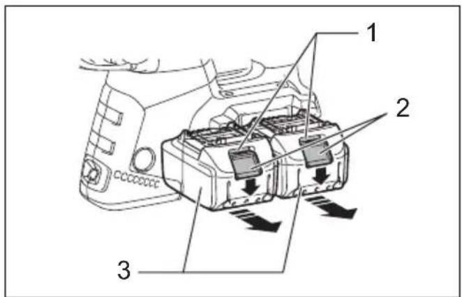
014402 015659
1
014417 014407 4
3
natural_image
Technical line drawing of a mechanical component with labeled part '8' (no text or symbols beyond label)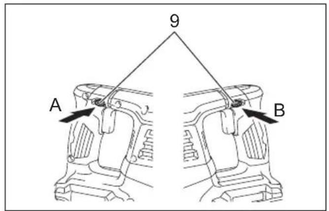
014408 014409
5
7
012823 012824
8
9
10
11 12
014399 014403
13 14
014404009664
15 16
014405 014420014405 014420
natural_image
Technical line drawing of a mechanical tool with a rotating knob and adjustment knob (no text or symbols)17 18
014421
014406
19 20
natural_image
Line drawing of a hand using a drill bit in a 3D coordinate system (no text or symbols)001300
014410
21 22
natural_image
Line drawing of a hand using a power tool to shoot material from a vertical surface (no text or symbols)002449
014415
23 24
014411
014416
014418 001145
25 26
27
014412
ENGLISH (Original instructions)
| Explanation of general view | ||
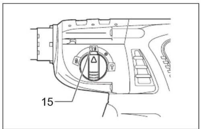
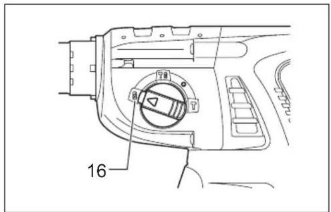
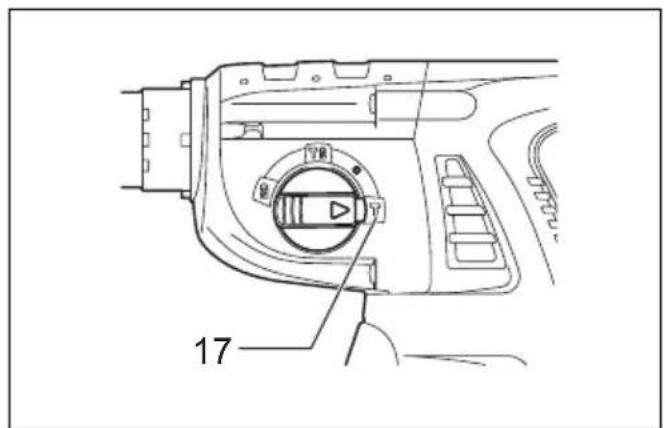
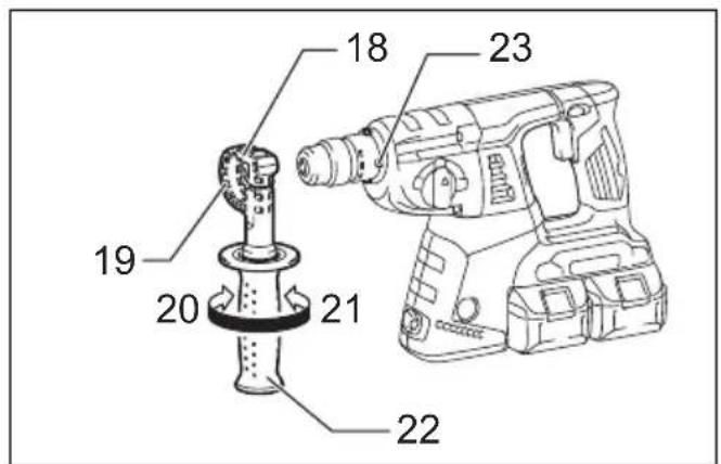
| 1 Red indicator | 14 Quick change drill chuck | 28 ○ symbol |
| 2 B u t t o n | 15 Rotation with hammering | 29 Action mode changing knob |
| 3 Battery cartridge | 16 Rotation only | 30 Depth gauge |
| 4 Indicator lamps | 17 Hammering only | 31 Dust cup |
| 5 Check button | 18 Grip base | 32 Blow-out bulb |
| 6 Battery indicator | 19 Teeth | 33 Chuck adapter |
| 7 Switch trigger | 20 Loosen | 34 Drill chuck |
| 8 L a m p | 21 Tighten | 35 Sleeve |
| 9 Reversing switch lever | 22 Side grip | 36 Ring |
| 10 Quick change chuck for SDS-plus | 23 Protrusion | 37 Limit mark |
| 24 Bit shank | 38 Brush holdre cap | |
| 11 Change cover line | 25 Bit grease | 39 Screwdriver |
| 12 Change cover | 26 Bit | |
| 13 Spindle | 27 Chuck cover | |
SPECIFICATIONS
| Model DHR263 DHR264 | |||
| Capacities | Concrete 26 mm | ||
| Steel 13 mm | |||
| Wood 32 mm | |||
| No load speed (min ^-1 ) 0 – 1,250 | |||
| Blows per minute 0 – 5,000 | |||
| Overall length 350 mm | 374 mm | ||
| Net weight | 4.1 – 5.1 kg | 4.2 – 5.1 kg | |
| Rated voltage | D.C. 36 V | ||
- Due to our continuing program of research and development, the specifications herein are subject to change without notice.
- Specifications may differ from country to country.
- The weight may differ depending on the attachment(s), including the battery cartridge. The lightest and heaviest combination, according to EPTA-Procedure 01/2014, are shown in the table.
Applicable battery cartridge and charger
| Battery cartridge | BL1815N / BL1820B / BL1830B / BL1840B / BL1850B / BL1860B |
| Charger | DC18RC / DC18RD / DC18RE / DC18SD / DC18SE / DC18SF / DC18SH / DC18WC |
- Some of the battery cartridges and chargers listed above may not be available depending on your region of residence.
WARNING: Only use the battery cartridges and chargers listed above. Use of any other battery cartridges and chargers may cause injury and/or fire.
Recommended cord connected power source
| Battery adapter | BAP182 |
| Cord connected battery pack | BL36120A |
- The cord connected power source(s) listed above may not be available depending on your region of residence.
- Before using the cord connected power source, read instruction and cautionary markings on them.
Intended use
The tool is intended for hammer drilling and drilling in brick, concrete and stone as well as for chiselling work. It is also suitable for drilling without impact in wood, metal, ceramic and plastic.
GEA010-2
General power tool safety warnings
WARNING: Read all safety warnings, instructions, illustrations and specifications provided with this power tool. Failure to follow all instructions listed below may result in electric shock, fire and/or serious injury.
Save all warnings and instructions for future reference.
The term “power tool” in the warnings refers to your mains-operated (corded) power tool or battery-operated (cordless) power tool.
GEB246-1
CORDLESS ROTARY HAMMER SAFETY WARNINGS
Safety instructions for all operations
- Wear ear protectors. Exposure to noise can cause hearing loss.
- Use auxiliary handle(s), if supplied with the tool. Loss of control can cause personal injury.
- Hold the power tool by insulated gripping surfaces, when performing an operation where the cutting accessory may contact hidden wiring. Cutting accessory contacting a "live" wire may make exposed metal parts of the power tool "live" and could give the operator an electric shock.
Safety instructions when using long drill bits with rotary hammers
-
Always start drilling at low speed and with the bit tip in contact with the workpiece. At higher speeds, the bit is likely to bend if allowed to rotate freely without contacting the workpiece, resulting in personal injury.
-
Apply pressure only in direct line with the bit and do not apply excessive pressure. Bits can bend, causing breakage or loss of control, resulting in personal injury.
Additional safety warnings
- Wear a hard hat (safety helmet), safety glasses and/or face shield. Ordinary eye or sun glasses are NOT safety glasses. It is also highly recommended that you wear a dust mask and thickly padded gloves.
- Be sure the bit is secured in place before operation.
- Under normal operation, the tool is designed to produce vibration. The screws can come loose easily, causing a breakdown or accident. Check tightness of screws carefully before operation.
- In cold weather or when the tool has not been used for a long time, let the tool warm up for a while by operating it under no load. This will loosen up the lubrication. Without proper warm-up, hammering operation is difficult.
-
Always be sure you have a firm footing. Be sure no one is below when using the tool in high locations.
-
Hold the tool firmly with both hands.
- Keep hands away from moving parts.
- Do not leave the tool running. Operate the tool only when hand-held.
- Do not point the tool at any one in the area when operating. The bit could fly out and injure someone seriously.
- Do not touch the bit, parts close to the bit, or workpiece immediately after operation; they may be extremely hot and could burn your skin.
- Some material contains chemicals which may be toxic. Take caution to prevent dust inhalation and skin contact. Follow material supplier safety data.
- Always be sure that the tool is switched off and the battery cartridge and the bit are removed before handing the tool to other person.
- Before operation, make sure that there is no buried object such as electric pipe, water pipe or gas pipe in the working area. Otherwise, the drill bit/chisel may touch them, resulting an electric shock, electrical leakage or gas leak.
- Do not operate the tool at no-load unnecessarily.
SAVE THESE INSTRUCTIONS.
⚠ WARNING: DO NOT let comfort or familiarity with product (gained from repeated use) replace strict adherence to safety rules for the subject product. MISUSE or failure to follow the safety rules stated in this instruction manual may cause serious personal injury.
ENC007-17
Important safety instructions for battery cartridge
- Before using battery cartridge, read all instructions and cautionary markings on (1) battery charger, (2) battery, and (3) product using battery.
- Do not disassemble or tamper with the battery cartridge. It may result in a fire, excessive heat, or explosion.
- If operating time has become excessively shorter, stop operating immediately. It may result in a risk of overheating, possible burns and even an explosion.
- If electrolyte gets into your eyes, rinse them out with clear water and seek medical attention right away. It may result in loss of your eyesight.
- Do not short the battery cartridge:
(1) Do not touch the terminals with any conductive material.
(2) Avoid storing battery cartridge in a container with other metal objects such as nails, coins, etc.
(3) Do not expose battery cartridge to water or rain.
A battery short can cause a large current flow, overheating, possible burns and even a breakdown.
- Do not store and use the tool and battery cartridge in locations where the temperature may reach or exceed 50 °C (122 °F).
-
Do not incinerate the battery cartridge even if it is severely damaged or is completely worn out. The battery cartridge can explode in a fire.
-
Do not nail, cut, crush, throw, drop the battery cartridge, or hit against a hard object to the battery cartridge. Such conduct may result in a fire, excessive heat, or explosion.
-
Do not use a damaged battery.
-
The contained lithium-ion batteries are subject to the Dangerous Goods Legislation requirements.
For commercial transports e.g. by third parties, forwarding agents, special requirement on packaging and labeling must be observed.
For preparation of the item being shipped, consulting an expert for hazardous material is required. Please also observe possibly more detailed national regulations.
Tape or mask off open contacts and pack up the battery in such a manner that it cannot move around in the packaging.
-
When disposing the battery cartridge, remove it from the tool and dispose of it in a safe place. Follow your local regulations relating to disposal of battery.
-
Use the batteries only with the products specified by Makita. Installing the batteries to non-compliant products may result in a fire, excessive heat, explosion, or leak of electrolyte.
-
If the tool is not used for a long period of time, the battery must be removed from the tool.
-
During and after use, the battery cartridge may take on heat which can cause burns or low temperature burns. Pay attention to the handling of hot battery cartridges.
-
Do not touch the terminal of the tool immediately after use as it may get hot enough to cause burns.
-
Do not allow chips, dust, or soil stuck into the terminals, holes, and grooves of the battery cartridge. It may cause heating, catching fire, burst and malfunction of the tool or battery cartridge, resulting in burns or personal injury.
-
Unless the tool supports the use near high-voltage electrical power lines, do not use the battery cartridge near high-voltage electrical power lines. It may result in a malfunction or breakdown of the tool or battery cartridge.
-
Keep the battery away from children.
SAVE THESE INSTRUCTIONS.
CAUTION: Only use genuine Makita batteries. Use of non-genuine Makita batteries, or batteries that have been altered, may result in the battery bursting causing fires, personal injury and damage. It will also void the Makita warranty for the Makita tool and charger.
Tips for maintaining maximum battery life
-
Charge the battery cartridge before completely discharged. Always stop tool operation and charge the battery cartridge when you notice less tool power.
-
Never recharge a fully charged battery cartridge. Overcharging shortens the battery service life.
-
Charge the battery cartridge with room temperature at 10 °C - 40 °C (50 °F - 104 °F). Let a hot battery cartridge cool down before charging it.
-
When not using the battery cartridge, remove it from the tool or the charger.
-
Charge the battery cartridge if you do not use it for a long period (more than six months).
FUNCTIONAL DESCRIPTION
CAUTION:
- Always be sure that the tool is switched off and the battery cartridge is removed before adjusting or checking function on the tool.
Installing or removing battery cartridge (Fig. 1)
CAUTION:
- Always switch off the tool before installing or removing of the battery cartridge.
- Hold the tool and the battery cartridge firmly when installing or removing battery cartridge. Failure to hold the tool and the battery cartridge firmly may cause them to slip off your hands and result in damage to the tool and battery cartridge and a personal injury.
To remove the battery cartridge, slide it from the tool while sliding the button on the front of the cartridge.
To install the battery cartridge, align the tongue on the battery cartridge with the groove in the housing and slip it into place. Insert it all the way until it locks in place with a little click. If you can see the red indicator on the upper side of the button, it is not locked completely.
CAUTION:
- Always install the battery cartridge fully until the red indicator cannot be seen. If not, it may accidentally fall out of the tool, causing injury to you or someone around you.
- Do not install the battery cartridge forcibly. If the cartridge does not slide in easily, it is not being inserted correctly.
NOTE:
- The tool does not work with only one battery cartridge.
Indicating the remaining battery capacity (Fig. 2) Only for battery cartridges with the indicator
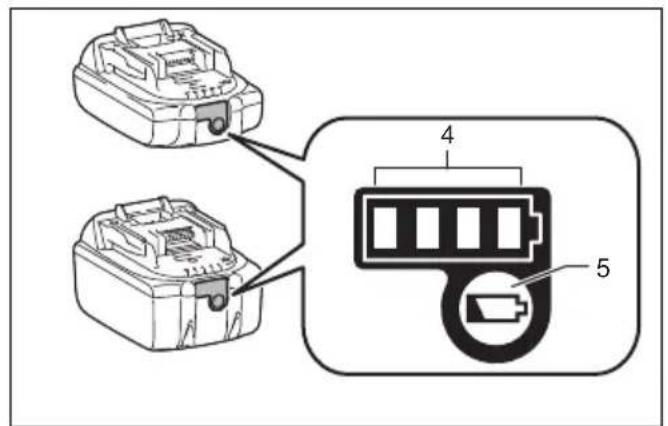
Press the check button on the battery cartridge to indicate the remaining battery capacity. The indicator lamps light up for a few seconds.
| Indicator lamps | Remaining capacity | ||
| Lighted Off Blinking | |||
| 75% to 100% | |||
| 50% to 75% | |||
| 25% to 50% | |||
| 0% to 25% | |||
| Charge the battery. | |||
| The battery may have malfunctioned. | |||
NOTE:
- Depending on the conditions of use and the ambient temperature, the indication may differ slightly from the actual capacity.
- The first (far left) indicator lamp will blink when the battery protection system works.
Tool/battery protection system
The tool is equipped with a tool/battery protection system.
This system automatically cuts off power to the motor to extend tool and battery life.
The tool will automatically stop during operation if the tool or battery are placed under one of the following conditions. In some conditions, the indicators light up.
Overload protection
When the tool is operated in a manner that causes it to draw an abnormally high current, the tool automatically stops without any indication. In this situation, turn the tool off and stop the application that caused the tool to become overloaded. Then turn the tool on to restart.
Overheat protection for battery
When the battery is overheated, the tool stops automatically without any indication. The tool does not start even if pulling the switch trigger. In this situation, let the battery cool before turning the tool on again.
Overdischarge protection (Fig. 3)
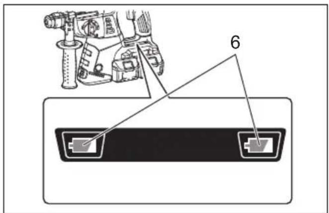
When the remaining battery capacity gets low, the battery indicator blinks on the applicable battery side. By further use, the tool stops and the battery indicator lights up about 10 seconds. In this situation, charge the battery cartridge.
Switch action (Fig. 4)

CAUTION:
- Before inserting the battery cartridge into the tool always check to see that the switch trigger actuates properly and returns to the "OFF" position when released.
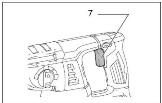
To start the tool, simply pull the switch trigger. Tool speed is increased by increasing pressure on the switch trigger. Release the switch trigger to stop.
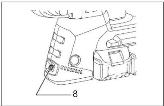
Lighting up the lamp (Fig. 5)

CAUTION:
- Do not look in the light or see the source of light directly.
Pull the switch trigger to light up the lamp. The lamp keeps on lighting while the switch trigger is being pulled. The light automatically goes out 10 - 15 seconds after the switch trigger is released.
NOTE:
- Use a dry cloth to wipe the dirt off the lens of the lamp. Be careful not to scratch the lens of lamp, or it may lower the illumination.
- Do not use thinner or gasoline to clean the lamp. Such solvents may damage it.
Reversing switch action (Fig. 6)
This tool has a reversing switch to change the direction of rotation. Depress the reversing switch lever from the A side for clockwise rotation or from the B side for counterclockwise rotation.
When the reversing switch lever is in the neutral position, the switch trigger cannot be pulled.

CAUTION:
- Always check the direction of rotation before operation.
- Use the reversing switch only after the tool comes to a complete stop. Changing the direction of rotation before the tool stops may damage the tool.
- When not operating the tool, always set the reversing switch lever to the neutral position.
Changing the quick change chuck for SDS-plus
For Model DHR264
The quick change chuck for SDS-plus can be easily exchanged for the quick change drill chuck.
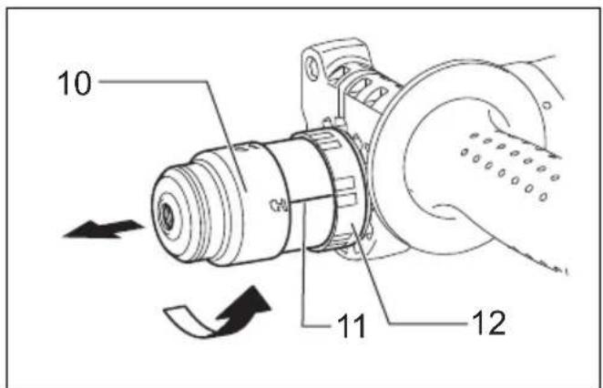
Removing the quick change chuck for SDS-plus (Fig. 7)

CAUTION:
- Before removing the quick change chuck for SDS-plus, always remove the bit.
Grasp the change cover of the quick change chuck for SDS-plus and turn in the direction of the arrow until the change cover line moves from the symbol to the symbol. Pull forcefully in the direction of the arrow.
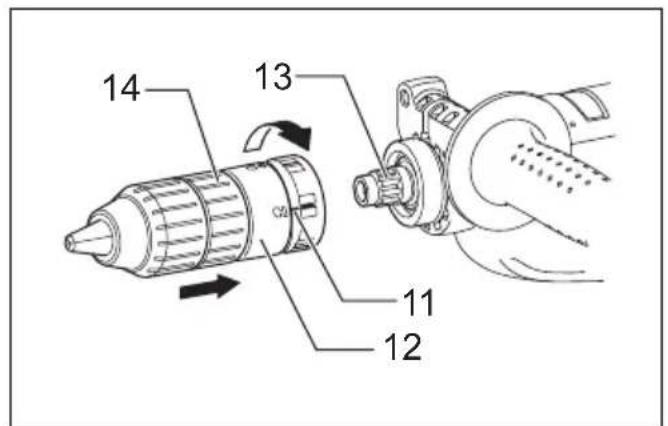
Attaching the quick change drill chuck (Fig. 8)
Check the line of the quick change drill chuck shows the symbol. Grasp the change cover of the quick change drill chuck and set the line to the symbol.
Place the quick change drill chuck on the spindle of the tool.
Grasp the change cover of the quick change drill chuck and turn the change cover line to the symbol until a click can clearly be heard.
Selecting the action mode
Rotation with hammering (Fig. 9)
For drilling in concrete, masonry, etc., depress the lock button and rotate the action mode changing knob to the symbol. Use a tungsten-carbide tipped bit.
Rotation only (Fig. 10)
For drilling in wood, metal or plastic materials, depress the lock button and rotate the action mode changing knob to the ⏻ symbol. Use a twist drill bit or wood bit.
Hammering only (Fig. 11)
For chipping, scaling or demolition operations, depress the lock button and rotate the action mode changing knob to the symbol. Use a bull point, cold chisel, scaling chisel, etc.

CAUTION:
- Do not rotate the action mode changing knob when the tool is running. The tool will be damaged.
- To avoid rapid wear on the mode change mechanism, be sure that the action mode changing knob is always positively located in one of the three action mode positions.
Torque limiter
The torque limiter will actuate when a certain torque level is reached. The motor will disengage from the output shaft. When this happens, the bit will stop turning.

CAUTION:
- As soon as the torque limiter actuates, switch off the tool immediately. This will help prevent premature wear of the tool.
- Hole saws cannot be used with this tool. They tend to pinch or catch easily in the hole. This will cause the torque limiter to actuate too frequently.
ASSEMBLY
CAUTION:
• Always be sure that the tool is switched off and the battery cartridge is removed before carrying out any work on the tool.
Side grip (auxiliary handle) (Fig. 12)
CAUTION:
• Always use the side grip to ensure operating safety.
Install the side grip so that the teeth on the grip fit in between the protrusions on the tool barrel. Then tighten the grip by turning clockwise at the desired position. It may be swung 360° so as to be secured at any position.
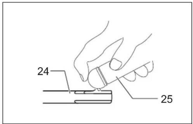
Bit grease
Coat the bit shank head beforehand with a small amount of bit grease (about 0.5 - 1 g). This chuck lubrication assures smooth action and longer service life.
Installing or removing the bit
Clean the bit shank and apply bit grease before installing the bit. (Fig. 13)
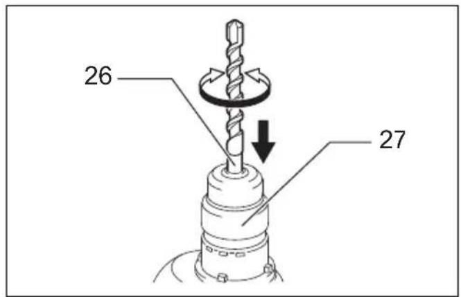
Insert the bit into the tool. Turn the bit and push it in until it engages.
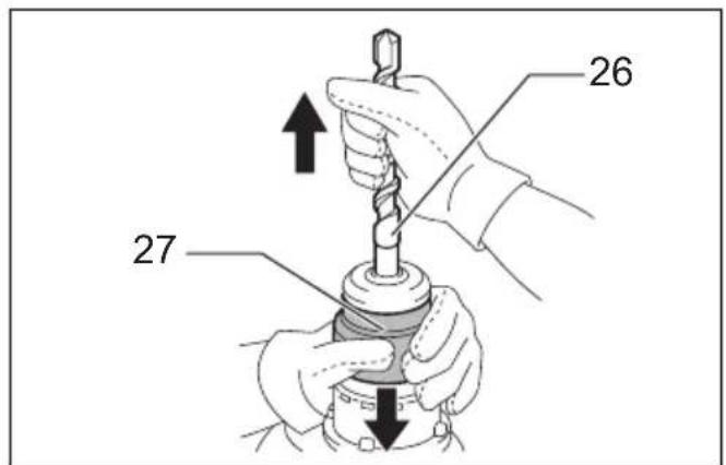
If the bit cannot be pushed in, remove the bit. Pull the chuck cover down a couple of times. Then insert the bit again. Turn the bit and push it in until it engages. (Fig. 14)
After installing, always make sure that the bit is securely held in place by trying to pull it out.
To remove the bit, pull the chuck cover down all the way and pull the bit out. (Fig. 15)
Bit angle (when chipping, scaling or demolishing) (Fig. 16 & 17)
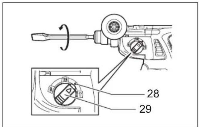
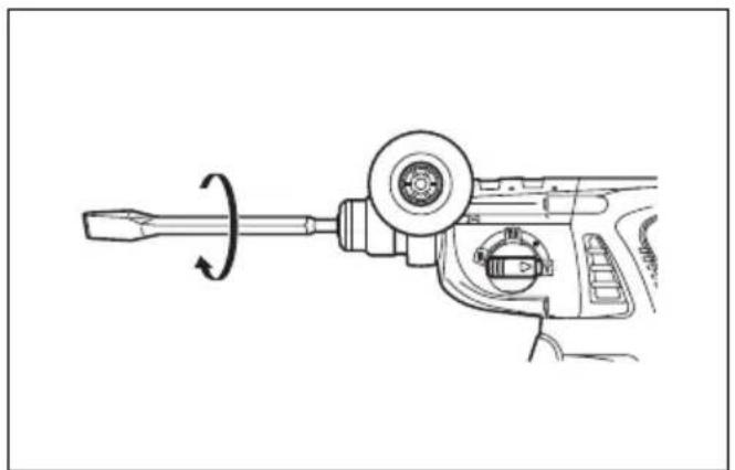
The bit can be secured at the desired angle. To change the bit angle, depress the lock button and rotate the action mode changing knob to the ○ symbol. Turn the bit to the desired angle.
Depress the lock button and rotate the action mode changing knob to the symbol. Then make sure that the bit is securely held in place by turning it slightly.
Depth gauge (Fig. 18)
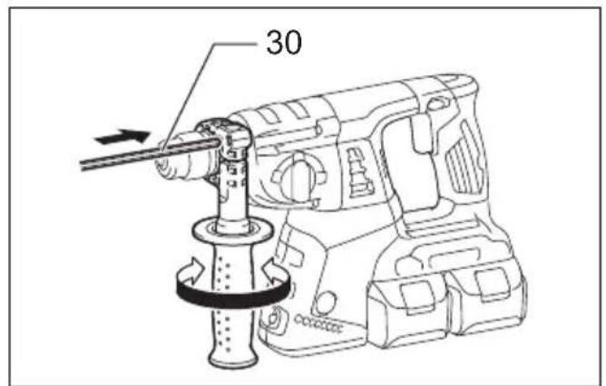
The depth gauge is convenient for drilling holes of uniform depth. Loosen the side grip and insert the depth gauge into the hole in the side grip. Adjust the depth gauge to the desired depth and tighten the side grip.
NOTE:
- The depth gauge cannot be used at the position where the depth gauge strikes against the gear housing.
Dust cup (Fig. 19)
Optional accessory
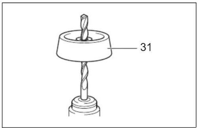
Use the dust cup to prevent dust from falling over the tool and on yourself when performing overhead drilling operations. Attach the dust cup to the bit as shown in the figure. The size of bits which the dust cup can be attached to is as follows.
| Bit diameter | |
| Dust cup 5 6 mm – | 14.5 mm |
| Dust cup 9 12 mm – | 16 mm |
006382
OPERATION
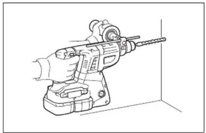
Hammer drilling operation (Fig. 20)
Set the action mode changing knob to the symbol.
Position the bit at the desired location for the hole, then pull the switch trigger.
Do not force the tool. Light pressure gives best results. Keep the tool in position and prevent it from slipping away from the hole.
Do not apply more pressure when the hole becomes clogged with chips or particles. Instead, run the tool at an idle, then remove the bit partially from the hole. By repeating this several times, the hole will be cleaned out and normal drilling may be resumed.
CAUTION:
- There is a tremendous and sudden twisting force exerted on the tool/bit at the time of hole breakthrough, when the hole becomes clogged with chips and particles, or when striking reinforcing rods embedded in the concrete. Always use the side grip (auxiliary handle) and firmly hold the tool by both side grip and switch handle during operations. Failure to do so may result in the loss of control of the tool and potentially severe injury.
NOTE:
- Eccentricity in the bit rotation may occur while operating the tool with no load. The tool automatically centers itself during operation. This does not affect the drilling precision.
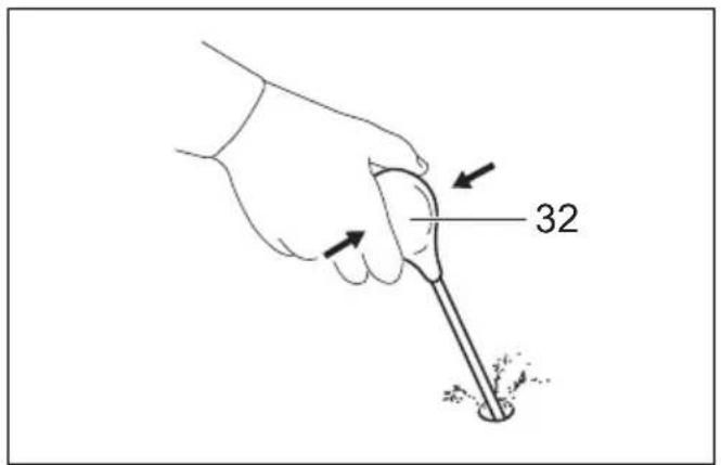
Blow-out bulb (optional accessory) (Fig. 21)
After drilling the hole, use the blow-out bulb to clean the dust out of the hole.
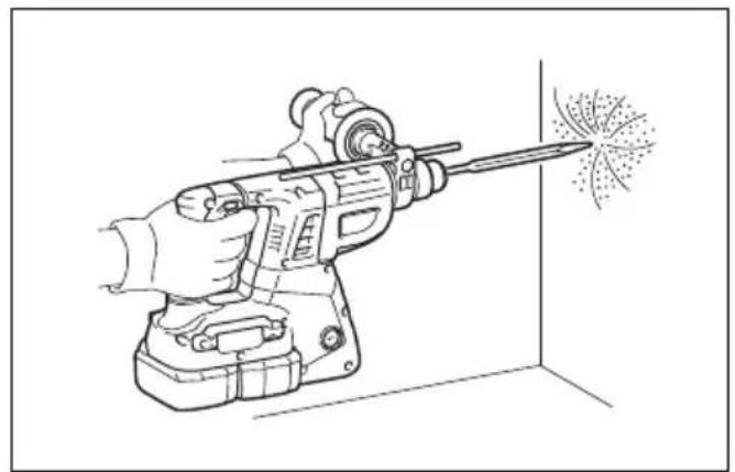
Chipping/Scaling/Demolition (Fig. 22)
Set the action mode changing knob to the symbol. Hold the tool firmly with both hands. Turn the tool on and apply slight pressure on the tool so that the tool will not bounce around, uncontrolled. Pressing very hard on the tool will not increase the efficiency.
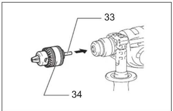
Drilling in wood or metal
Use the optional drill chuck assembly. When installing it, refer to "Installing or removing the bit" described on the previous page.
Set the action mode changing knob so that the pointer points to the 🔊 symbol.
Use the quick change drill chuck as standard equipment. When installing it, refer to "Changing the quick change chuck for SDS-plus" described on the previous page.
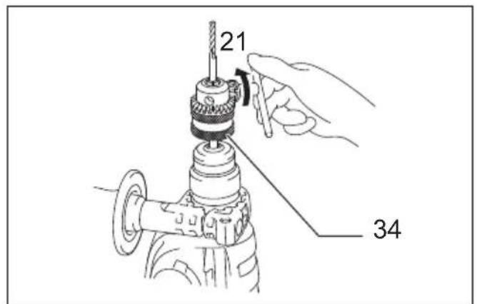
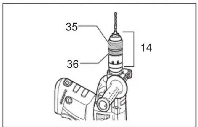
Hold the ring and turn the sleeve counterclockwise to open the chuck jaws. Place the bit in the chuck as far as it will go. Hold the ring firmly and turn the sleeve clockwise to tighten the chuck. To remove the bit, hold the ring and turn the sleeve counterclockwise.
Set the action mode changing knob to the ⏻ symbol.
You can drill up to 13 mm diameter in metal and up to 32 mm diameter in wood.

CAUTION:
- Never use "rotation with hammering" when the drill chuck assembly is installed on the tool. The drill chuck assembly may be damaged. Also, the drill chuck will come off when reversing the tool.
- Pressing excessively on the tool will not speed up the drilling. In fact, this excessive pressure will only serve to damage the tip of your bit, decrease the tool performance and shorten the service life of the tool.
- There is a tremendous twisting force exerted on the tool/bit at the time of hole breakthrough. Hold the tool firmly and exert care when the bit begins to break through the workpiece.
- A stuck bit can be removed simply by setting the reversing switch to reverse rotation in order to back out. However, the tool may back out abruptly if you do not hold it firmly.
• Always secure small workpieces in a vise or similar hold-down device.
MAINTENANCE

CAUTION:
- Always be sure that the tool is switched off and the battery cartridge is removed before attempting to perform inspection or maintenance.
- Never use gasoline, benzine, thinner, alcohol or the like. Discoloration, deformation or cracks may result.
Replacing carbon brushes (Fig. 26 & 27)
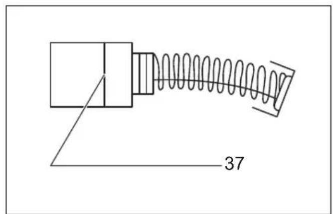
Remove and check the carbon brushes regularly. Replace when they wear down to the limit mark. Keep the carbon brushes clean and free to slip in the holders. Both carbon brushes should be replaced at the same time. Use only identical carbon brushes.
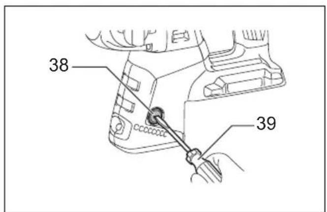
Use a screwdriver to remove the brush holder caps. Take out the worn carbon brushes, insert the new ones and secure the brush holder caps.
Remount the holder cap covers on the tool.
To maintain product SAFETY and RELIABILITY, repairs, any other maintenance or adjustment should be performed by Makita Authorized Service Centers, always using Makita replacement parts.
OPTIONAL ACCESSORIES

CAUTION:
• These accessories or attachments are recommended for use with your Makita tool specified in this manual. The use of any other accessories or attachments might present a risk of injury to persons. Only use accessory or attachment for its stated purpose.
If you need any assistance for more details regarding these accessories, ask your local Makita Service Center.
• SDS-Plus Carbide-tipped bits
- Bull point
- Cold chisel
- Scaling chisel
- Grooving chisel
- Drill chuck assembly
- Drill chuck S13
- Chuck adapter
- Chuck key S13
- Bit grease
- Side grip
- Depth gauge
- Blow-out bulb
- Dust cup
- Dust extractor attachment
- Plastic carrying case
• Keyless drill chuck
- Makita genuine battery and charger
NOTE:
- Some items in the list may be included in the tool package as standard accessories. They may differ from country to country.
ENG905-1
Noise
The typical A-weighted noise level determined according to EN62841-2-6:
Model DHR263
Sound pressure level ( L_pA ): 95 dB (A)
Sound power level ( L_WA ): 103 dB (A)
Uncertainty (K): 3 dB (A)
Model DHR264
Sound pressure level ( L_pA ): 94 dB (A)
Sound power level (LWA): 102 dB (A)
Uncertainty (K): 3 dB (A)
ENG907-1
NOTE:
- The declared noise emission value(s) has been measured in accordance with a standard test method and may be used for comparing one tool with another.
- The declared noise emission value(s) may also be used in a preliminary assessment of exposure.

WARNING:
- Wear ear protection.
- The noise emission during actual use of the power tool can differ from the declared value(s) depending on the ways in which the tool is used especially what kind of workpiece is processed.
- Be sure to identify safety measures to protect the operator that are based on an estimation of exposure in the actual conditions of use (taking account of all parts of the operating cycle such as the times when the tool is switched off and when it is running idle in addition to the trigger time).
ENG900-1
Vibration
The following table shows the vibration total value (triaxial vector sum) determined according to applicable standard.
Model DHR263
| Work mode | Vibration emission | Uncertainty (K) | Applicable standard / Test condition |
| Hammer drilling into concrete ( a_h, HD ) | 17.6 m/s ^2 | 1.8 m/s ^2 | EN 62841-2-6 |
| Chiselling ( a_h, CHeq ) | 14.3 m/s ^2 | 1.5 m/s ^2 | EN 62841-2-6 |
Model DHR264
| Work mode | Vibration emission | Uncertainty (K) | Applicable standard / Test condition |
| Hammer drilling into concrete ( a_h, HD ) | 16.5 m/s ^2 | 2.0 m/s ^2 | EN 62841-2-6 |
| Chiselling ( a_h, CHeq ) | 14.5 m/s ^2 | 1.5 m/s ^2 | EN 62841-2-6 |
ENG901-2
NOTE:
- The declared vibration total value(s) has been measured in accordance with a standard test method and may be used for comparing one tool with another.
- The declared vibration total value(s) may also be used in a preliminary assessment of exposure.

WARNING:
- The vibration emission during actual use of the power tool can differ from the declared value(s) depending on the ways in which the tool is used especially what kind of workpiece is processed.
- Be sure to identify safety measures to protect the operator that are based on an estimation of exposure in the actual conditions of use (taking account of all parts of the operating cycle such as the times when the tool is switched off and when it is running idle in addition to the trigger time).
Declarations of Conformity
For European countries only
The Declarations of conformity are included in Annex A to this instruction manual.
Descriptif
OPTIONELE ACCESSOIRES
LET OP:
- Intended use
- General power tool safety warnings
- CORDLESS ROTARY HAMMER SAFETY WARNINGS
- Safety instructions for all operations
- Additional safety warnings
- SAVE THESE INSTRUCTIONS.
- Important safety instructions for battery cartridge
- Tips for maintaining maximum battery life
- FUNCTIONAL DESCRIPTION
- CAUTION:
- Installing or removing battery cartridge (Fig. 1)
- NOTE:
- Indicating the remaining battery capacity (Fig. 2) Only for battery cartridges with the indicator
- Tool/battery protection system
- Overload protection
- Overheat protection for battery
- Overdischarge protection (Fig. 3)
- Switch action (Fig. 4)
- Lighting up the lamp (Fig. 5)
- Reversing switch action (Fig. 6)
- Changing the quick change chuck for SDS-plus
- For Model DHR264
- Removing the quick change chuck for SDS-plus (Fig. 7)
- Attaching the quick change drill chuck (Fig. 8)
- Selecting the action mode
- Rotation with hammering (Fig. 9)
- Rotation only (Fig. 10)
- Hammering only (Fig. 11)
- Torque limiter
- ASSEMBLY
- Side grip (auxiliary handle) (Fig. 12)
- Bit grease
- Installing or removing the bit
- Bit angle (when chipping, scaling or demolishing) (Fig. 16 & 17)
- Depth gauge (Fig. 18)
- Dust cup (Fig. 19)
- Optional accessory
- OPERATION
- Hammer drilling operation (Fig. 20)
- Blow-out bulb (optional accessory) (Fig. 21)
- Chipping/Scaling/Demolition (Fig. 22)
- Drilling in wood or metal
- MAINTENANCE
- Replacing carbon brushes (Fig. 26 & 27)
- OPTIONAL ACCESSORIES
- Noise
- Model DHR263
- Model DHR264
- WARNING:
- Vibration
- Declarations of Conformity
- For European countries only
- OPTIONELE ACCESSOIRES
- LET OP:
Brand : MAKITA
Model : DHR264ZJ
Category : Drill driver