
BDPS200 - Peinture en spray BLACK & DECKER - Free user manual and instructions
Find the device manual for free BDPS200 BLACK & DECKER in PDF.


| Product type | Paint sprayer |
| Brand | Black & Decker |
| Model | BDPS200 |
| Power supply | Mains electric 220-240 V, 50 Hz |
| Rated power | 500 W |
| Dimensions (L × W × H) | 30 × 20 × 15 cm |
| Weight | 1.4 kg |
| Container capacity | 800 ml |
| Spray rate | Adjustable, up to 500 ml/min |
| Nozzle | Interchangeable, diameters 1.0 / 1.5 / 2.0 mm |
| Compatible paint types | Acrylic paints, latex, varnishes, lacquers |
| Maximum viscosity | Approx. 60 DIN-s (ready to use) |
| Main functions | Homogeneous spraying, jet adjustment, child safety |
| Maintenance | Clean after each use with water or suitable solvent |
| Safety | Do not use near flames; wear mask and goggles recommended |
| Spare parts | Nozzle, container, seal, filter |
| Repairability | Repairability index: 7.5/10 (parts available) |
| Warranty | 2 years |
| Included accessories | 3 nozzles, filling cup, cleaning brush |
| Noise level | 75 dB(A) |
| Operating temperature | 5 °C to 40 °C |
Frequently Asked Questions - BDPS200 BLACK & DECKER
User questions about BDPS200 BLACK & DECKER
0 question about this device. Answer the ones you know or ask your own.
Ask a new question about this device
Download the instructions for your Peinture en spray in PDF format for free! Find your manual BDPS200 - BLACK & DECKER and take your electronic device back in hand. On this page are published all the documents necessary for the use of your device. BDPS200 by BLACK & DECKER.
USER MANUAL BDPS200 BLACK & DECKER
Thank you for choosing Black & Decker! Go to www.BlackandDecker.com/NewOwner to register your new product.
PLEASE READ BEFORE RETURNING THIS PRODUCT FOR ANY REASO
If you have a question or experience a problem with your Black & Decker WWW.BLACKANDDECKER.COM/INSTANTANSWERS for instant answers 24 hour
If you can't find the answer or do not have access to the internet, call 1-800-544-6986 from 8 a.m. to 5 p.m. EST Mon. - Fri. to speak with Please have the catalog number available when you call.
SAVE THIS INSTRUCTION MANUAL FOR FUTURE REFERENCE.
VEAELESPAÑOLENLACONTRAPORTADA.
Important Safety Instructions ....3
General Safety Warnings....4
Grounding Instructions....4
Extension Cords....5
Components......6
Set-Up....7
Selecting The Proper Spray Nozzle....7
Attaching The Spray Nozzles....7
Adjusting The Fan Spray Nozzle....7
Liquid Material Preparation 8
Preparation Tips....8
Filling The Canister 8
Flow Control Settings....9
Operation 9
On/Off Switch....9
Spraying Technique....9
Cleaning....10
Reassembly 12
Maintenance 13
Accessories....13
Service Informaiton 13
Warranty....14
Troubleshooting 14
SAFETY GUIDELINES - DEFINITIONS
It is important for you to read and understand this manual. The information it contains relates to protectir SAFETY and PREVENTING PROBLEMS. The symbols below are used to help you recognize this informat
⚠️DANGER: Indicates an imminently hazardous situation which, if not avoided, will result in death or serious injury.
WARNING: Indicates a potentially hazardous situation which, if not avoided, could result in death or serious injury.
⚠️CAUTION: Indicates a potentially hazardous situation which, if not avoided, may result in minor or moderate injury.
NOTICE: Used without the safety alert symbol indicates a potentially hazardous situation which, if not avoided, may result in property damage.
The following are explanations of important safety hazard pictorials in this manual.

- Read and understand the instruction manual.
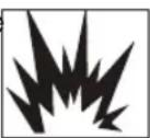
- Explosion hazard.

- Electric shock hazard.

- Fire hazard.

- Respiratory hazard.
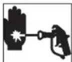
- Skin injection hazard.
IMPORTANT SAFETY INSTRUCTIONS
SAVE THESE INSTRUCTIONS - To reduce the risks of fire or explosion, electrical shock and the injury to persons, read and understand all instructions included in this manual. Be familiar with the controls and t usage of the equipment.
• This product is intended for household use only.

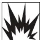
⚠ WARNING: FIRE OR EXPLOSION HAZARD. Solvent and spray material fumes can explode or ignite. Severe injury or property damage can occur.
To avoid these risks, take the following preventions:
- Exhaust and fresh air introduction must be provided to keep the air within the spray area free from ac flammable vapors.
- Keep spray area well ventilated
- Avoid all ignition sources such as static electricity sparks, open flames, pilot lights, hot objects, lit tobacco products, and sparks from connecting and disconnecting power cords or working light switches.
- Fire extinguisher equipment shall be present and working."
- Keep area clean and free of paint or solvent containers, rags, and other flammable materials.
- Follow the material and solvent manufacturer's safety precautions and warnings.
- Do not spray flammable or combustible materials near an open flame or sources of ignition such as lit products, motors, and electrical equipment.
- Know the contents of the spray materials and their cleaning solvents. Read all Material Safety Data Sh and container labels provided with the spray materials and solvents. Follow the spray material and solve manufacturer's safety instructions.
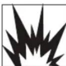
⚠ WARNING: EXPLOSION HAZARD DUE TO INCOMPATIBLE MATERIALS. Severe injury or property damage can occur.
To avoid these risks, take the following preventions:
- Do not use bleach.
- Do not use halogenated hydrocarbon solvents such as methylene chloride and 1,1,1 - trichloroethane. The compatible with aluminum and may cause an explosion. If you are unsure of a material's compatibility with aluminum, contact your coating supplier.
- Keep spray area well ventilated

WARNING: HAZARDOUS VAPORS. Spray materials, solvents, and other materials can be harmful if inhaled or come in contact with the body. Vapors can cause severe nausea, fainting, or poise
To avoid these risks, take the following preventions:
- Keep spray area well ventilated.
- Use a respirator or mask if vapors can be inhaled. Read all instructions supplied with the mask to be provide the necessary protection.
- Wear protective eyewear.
- Wear protective clothing as required by coating manufacturer.
To avoid these risks, take the following preventions
- Keep electrical cord plug and sprayer trigger free from spray material and other liquids. Never hold cord connections to support cord. Failure to observe may result in an electrical shock.
- Never immerse electrical parts in water or any other liquid. Wipe the exterior of the sprayer with a dar cleaning. Always make sure the sprayer is unplugged before taking it apart for cleaning.
- Do not expose unit to rain or wet conditions.
- Do not abuse the cord. Never use the cord to carry the unit or pull the plug from an outlet. Keep co oil, sharp edges or moving parts. Replace damaged cords immediately.
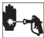
WARNING: SKIN INJECTION HAZARD. May cause severe injury.
To avoid these risks, take the following preventions
- NEVER aim the sprayer at any part of the body.
- Do not aim the sprayer at, or spray any person or animal.
- NEVER allow any part of the body to come in contact with the fluid stream.
- NEVER put your hand in front of the sprayer. Wear gloves. Gloves will not provide protection against an injection injury.
- Keep hands and other body parts away from the discharge. For example, do not try to stop leaks with any part of the body.
• Always unplug the sprayer before servicing, cleaning tip guard, changing tips, or leaving unattended.
• Always use the nozzle tip guard. Do not spray without nozzle tip guard in place. - Only use a nozzle tip specified by the manufacturer.
- Use caution when cleaning and changing nozzle tips. In the case where the nozzle tip clogs while spra manufacturer's instructions.
- High-pressure spray is able to inject toxins into the body and cause serious bodily injury. In the event that injection occurs, seek medical attention immediately.
- Verify that all connections are secure before operating the unit.
GENERAL SAFETY WARNINGS
⚠ WARNING: GENERAL. To Reduce the risk of severe injury or property damage.
To avoid these risks, take the following preventions:
• Always wear appropriate gloves, eye protection, and a respirator or mask when painting.
- Do not aim the sprayer at, or spray any person, including self, or animal.
- Do not spray outdoors on windy days
- Wear protective clothing to keep spray material off skin and hair.
• Follow all appropriate local, state, and national codes governing ventilation, fire prevention, and operation.
• Always use appropriate gloves, eye protection and a respirator or mask when spraying, thinning, mixing, pouring, or cleaning.
- Do not operate or spray near children. Keep children away from equipment at all times. Keep sprayer reach of children.
- Do not overreach or stand on an unstable support. Keep effective footing and balance at all times.
- Stay alert and watch what you are doing.
- Do not operate the unit when fatigued or under the influence of drugs or alcohol.
- Read all instructions and safety precautions for equipment and spray material before operating any equip
• Hearing protection is recommended for extended use.
GROUNDING INSTRUCTIONS
This product must be grounded. In the event of an electrical short circuit, grounding reduces the risk of by providing an escape wire for the electric current. This product is equipped with a cord having a group an appropriate grounding plug. The plug must be plugged into an outlet that is properly installed and ground accordance with all local codes and ordinances. Connect to a grounded outlet and use grounded extension not use a 3 to 2 adapter.

WARNING: ELECTRIC SHOCK HAZARD. Improper installation of the grounding plug is able to result in a risk of electric shock. When repair replacement of the cord or plug is required, do not connect the ground either flat blade terminal. The wire with insulation having an outer surface green with or without yellow stripes is the grounding wire.
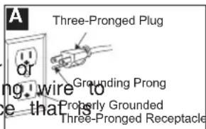
This product is for use on a nominal 120-V circuit and has a grounding plug similar to the plug illustrat connect the product to an outlet having the same configuration as the plug. Do not use an adapter with Check with a qualified electrician or serviceman when the grounding instructions are not completely under
when in doubt as to whether the product is properly grounded. Do not modify the plug provided; if it does not fit the outlet, have the proper outlet installed by a qualified electrician. modify the plug provided; if it does not fit the outlet, have the proper outlet installed by a qualified electrician.
EXTENSION CORDS
Use only a 3-wire extension cord that has a 3-blade grounding plug and a 3-slot receptacle that will accept the plug on the product. Make sure your extension cord is in good condition. When using an extension cord, be sure to use one heavy enough to carry the current your product will draw. An undersized cord will cause a drop in line voltage resulting in loss of power and overheating. If an extension cord is to be used outdoors, it must be marked with the suffix W-A after the cord type designation. For example, a designation of SJTW-A would indicate that the cord would be appropriate for outdoor use. For proper size cords see chart below.
| Minimum Gauge for Cord Sets | |||||
| Volts | Total Length of Cord in Feet | ||||
| 120V | 0-25 | 26-50 | 51-100 | 101-150 | |
| (0-7,6m) | (7,6-15,2m) | (15,2-30,4m) | (30,4-45,7m) | ||
| 240V | 0-50 | 51-100 | 101-200 | 201-300 | |
| (0-15,2m) | (15,2-30,4m) | (30,4-60,9m) | (60,9-91,4m) | ||
| Ampere Rating | |||||
| More | Not more | American | Wire | Gauge | |
| Than | Than | ||||
| 0 | - | 6 | 18 | 16 | 16 |
| 6 | - | 10 | 18 | 16 | 14 |
| 10 | - | 12 | 16 | 16 | 14 |
| 12 | - | 16 | 14 | 12 | Not Recommended |
⚠ WARNING: Some spray materials contain chemicals known to the State of California to cause cancer, birth defects or other reproductive harm. To reduce your exposure wear appropriate safety equipment such as face masks, gloves, and other appropriate protective equipment. Please review and follow the safety precautions on the paint container.
COMPONENTS
A
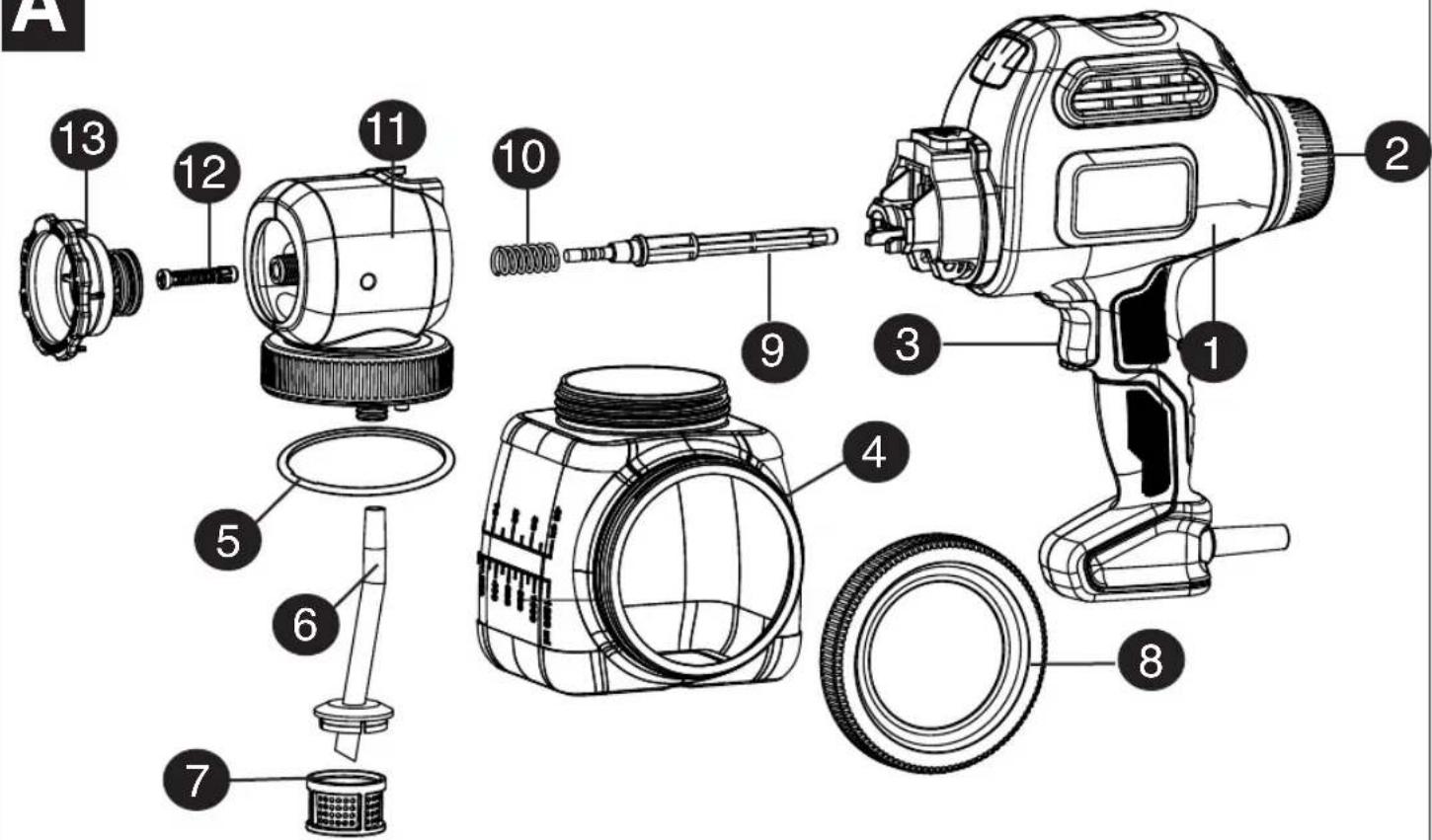
FUNCTIONAL DESCRIPTION
1.) Paint sprayer
2.) Flow control knob
3.) Trigger
4.) Side fill canister
5.) O-ring
6.) Pickup tube
7.) Pickup tube filter
8.) Lid
9.) Piston
10.) Piston spring
11.) Valve body assembly
12.) Atomizer valve
13.) Fan nozzle (green)
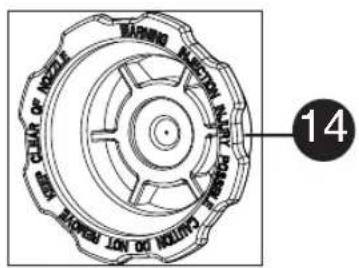
14.) Cone nozzle (blue)
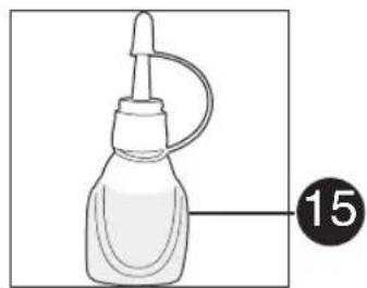
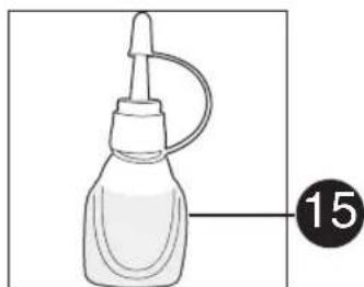
15.) Oil lubricant
16.) Cleaning brush
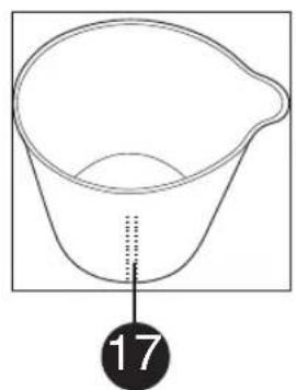
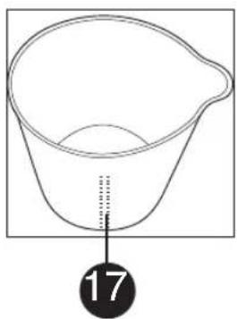
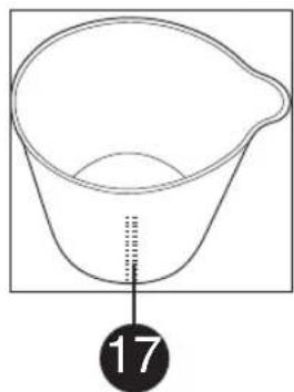
17.) Mixing bucket
18.) Cleaning pin
natural_image
Illustration of a bottle with a cap and tube, labeled with number 15 (no text or symbols on the bottle itself)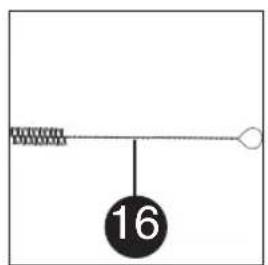
natural_image
Simple line drawing of a conical container with a handle and a dotted line indicating depth (no text or symbols)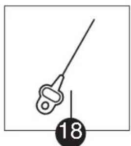
natural_image
Simple line drawing of a medical or surgical tool with a numbered label (18) below it, no text or symbols present.SET-UP
⚠ WARNING: ⚠ sure to use appropri
protective gear and unplug unit.
⚠ WARNING: Make sure area is well ventilated and free of flammable vapors.
SELECTING THE PROPER SPRAY
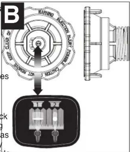
NOZZLE - (FIGURES B AND B1)
The sprayer includes two standard nozzles that are colored coded for ease of identification.
Fan (wide) nozzle (green - figure B) - This nozzle has a spring attached to the back which allows for adjustments for spraying both vertically and horizontally. It also has tabs on the side which match the spray pattern when set for spraying side to side and top to bottom. The spray pattern covers a wide area. This is the spray nozzle that is identified as diagram on top of the sprayer.
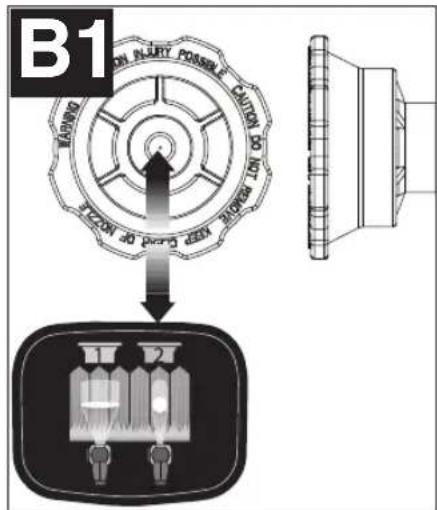
Cone nozzle (blue - figure B1) - The cone nozzle spray pattern is more concentrated. Use this nozzle for items that are too small for the fan nozzle. This is the spray nozzle that is identified as number 2 in the diagram sprayer.
ATTACHING THE SPRAY NOZZLES - (FIGURES C AND C1)
To attach the green fan spray nozzle:
• Make sure cord is unplugged.
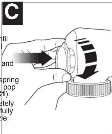
- Thread the nozzle onto the spindle ur you feel a little resistance (about 10 ful turns).
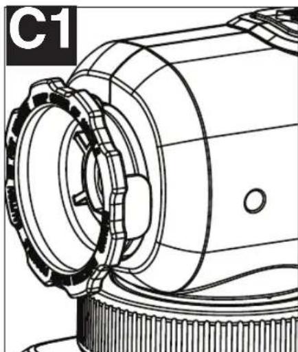
- Push in on the spring loaded nozzle and turn until it is fully seated (figure C).
- Once the nozzle is fully seated, the spring on the back of the nozzle will make it pop out slightly when it is released (figure C1).
• Make sure fan spray nozzle is completely threaded on by hand only. If it is not fully seated in can leak or damage the nozzle.
To remove the green fan spray nozzle:
- Press in on the nozzle and turn counterclockwise.
natural_image
Technical line drawing of a mechanical component with gears and shaft (no text or symbols)To attach the blue cone spray nozzle:
- Thread the nozzle onto the spindle until it is fully seated.
- Make sure cone spray nozzle is completely threaded on by hand only. If it is not fully seated in can the nozzle.
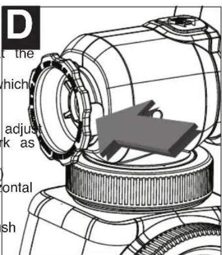
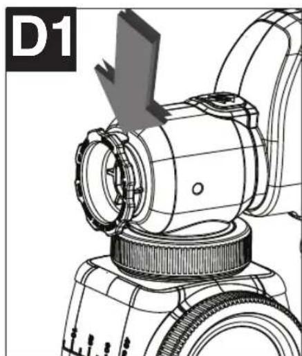
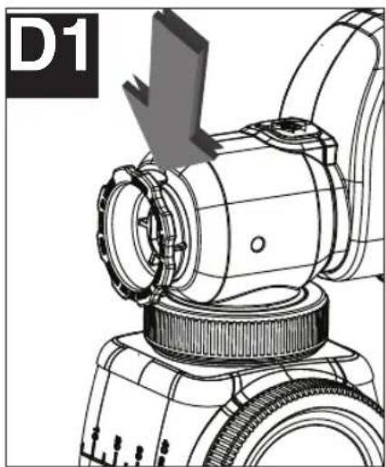
ADJUSTING THE FAN SPRAY NOZZLE - (FIGURES D AND D1)
To adjust the fan spray nozzle:
• Make sure cord is unplugged and that the fan spray nozzle is fully hand-tightened.
- The fan spray nozzle has two tabs which align to indicate vertical and horizontal positions.
- If you will be spraying (side to side) adjust the nozzle to align with the vertical mark as shown in figure D.
- If you will be spraying (up and down) adjust the nozzle to align with the horizontal mark as shown in figure D1.
⚠️ CAUTION: Do not compress or push spring when adjusting fan pattern. The nozzle should rotate and not loosen.
natural_image
Technical line drawing of a mechanical device with a gear and adjustment arrow (no text or symbols)LIQUID MATERIAL PREPARATION - (FIGURES E, E1)
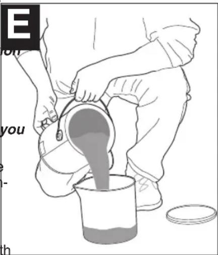
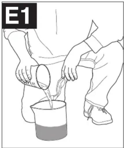
TIP: Make sure the type of material you use can be cleaned with either mineral spirits or paint thinner (for oil-based paints) or a warm water and soap solut (for water soluble paints like latex). Use drop cloths during pouring, mixing, and viscosity testing of materials to be sprayed to protect your floors and anything else in the spraying area that wish to remain untouched.
The liquid being sprayed may need to be thinned (diluted) before starting. When thinning, use the proper liquid thinner recommended on the container by the material manufacturer and the proper dilution rate.
⚠ WARNING: Do not use materials with a flashpoint higher than 60°C (140°F).
natural_image
Illustration of a person pouring liquid from a beaker into a container (no text or symbols)
A 2- 3/4 quart mixing bucket is provided to use when transferring spray material from the original container into the bucket for thinning and measuring purposes (figure E).
- If material needs thinning, add the appropriate liquid thinning material recommended by the manufacturer (figure E1).
- The quick clean fill cup has a measurement of 2.5 ozs. This can be used as a quick measurement wl 5% in the side fill canister.
- It is possible to spray latex paint with this unit, however, the required thinning may exceed material man recommendation. The operator should consider the type of application and final location of the project when
| COMMON DILUTION RATES ON PAINT CAN | |
| MANUFACTURERS SUGGESTED OUNCES PER GALLON | |
| 1/2 pint 8 ounces | |
| 5% 6-1/2 ounces | |
| 10% 13 ounces | |
PREPARATION TIPS
- With any spraying job you should always ensure that you have properly prepared the surface to get the That is, that all surfaces are free from dust, dirt, rust and grease. Lightly pressure wash decks or exterior surfaces and ensure that they are dry before spraying.
- It is recommended that you mask all edges and other areas and use drop cloths to protect your floors else in the spraying area that you wish to remain untouched.
- Skin that forms on the top of paint can clog the sprayer. Remove skin before mixing. Older material m strained with a funnel with a filter attached or through hosiery to remove any impurities that could clog sy
- Before starting have gloves, paper towels, rags etc. available for unexpected spills.
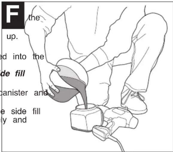
FILLING THE CANISTER - (FIGURE F)
- Check to make sure that the canister is completely screwed sprayer.
- Lay the sprayer on its side with the canister side lid facing up.
- Unscrew the lid on the side of the canister.
- Pour the properly thinned and strained material to be sprayed into side fill canister (figure F). TIP: Use the mixing bucket provided to pour material from the original material container into the side fill canister.
- Clean any residual liquid from the threads or sides of the canister sprayer.
- Starting the threads evenly, screw the lid completely onto the side fill canister. Check the lid to make sure it is threaded on squarely and completely before picking up the sprayer.
FLOW CONTROL SETTINGS
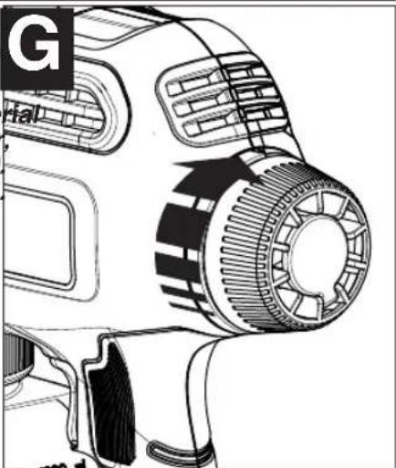
FLOW CONTROL KNOB - (FIGURE G)
The flow control knob regulates the amount of liquid that can be spraye
- Select low (1), medium (5) or high (9) on the flow control knob.
TIP: Always test the spray pattern on scrap cardboard or similar mate first. Begin with flow control knob on the highest flow setting. Heavier thicker materials should be sprayed on the higher setting closer to #9. Thinner materials should be sprayed on the lower setting closer to #1.
natural_image
Technical line drawing of a handheld device with gear and housing (no text or symbols)OPERATION
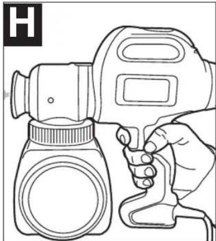
ON / OFF TRIGGER - (FIGURE H)
The sprayer is turned on and off by the trigger.
• To turn the sprayer on, squeeze the trigger.
• To turn the sprayer off, release the trigger.
⚠ WARNING: Risk of injury. Never point the sprayer at any part of the body. Never pull the trigger while adjusting the spray setting.
natural_image
Line drawing of a hand holding a handheld device with a cap and bulb (no text or symbols)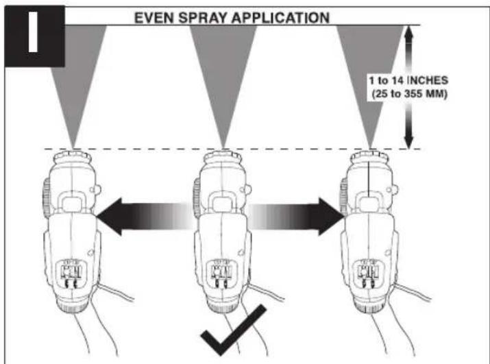
DEVELOPING THE PROPER SPRAYING TECHNIQUE
- Practice spraying on a piece of scrap material such as cardboard to test your spray pattern and become the speed settings flow control features of the sprayer.
- Ensure surface to be sprayed is free of dust, dirt, and grease.
- Ensure spray area is clean and free of dust that could be blown onto newly sprayed surfaces.
- Cover any areas not intended to be sprayed.
• Always spray from a minimum of 1 inch (25mm) to a maximum of 14 inches (355mm) (figure I). Optimal is usually around 10 inches or use a paint stir stick as a reference. - A commonly used method for spraying a large surface is the "crisscross" pattern. This is done by spray horizontal strips and then crossing over these strips with vertical strips.
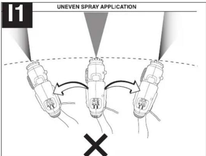
• To get an even spray distribution, always keep your arm at the same distance (figure I) from the surface you are spraying and avoid moving your wrist (figure I1).
- Maintain smooth and consistent speed which will help avoid inconsistencies. Begin spraying after the pass begun and release trigger before stopping the pass.
- Avoid spraying too heavily in any one area. Several lighter coats are better than one heavy coat which running and dripping. Remember that the flow control knob regulates the amount of liquid that can be spr the flow knob counterclockwise increases the flow of liquid. Turning the knob clockwise decreases the flow runs or drips do occur, have a dry paint brush on hand to smooth them out.
WARNING: ELECTRIC SHOCK HAZARD. When spraying overhead, never tip the sprayer more than 45 degrees. The material being sprayed could leak into the motor housing.
TIP: If the atomizer valve is not seated properly, spray material will leak from behind spray nozzle. If
material is leaking, turn off and unplug sprayer from power source immediately. Follow these steps to correct the problem:
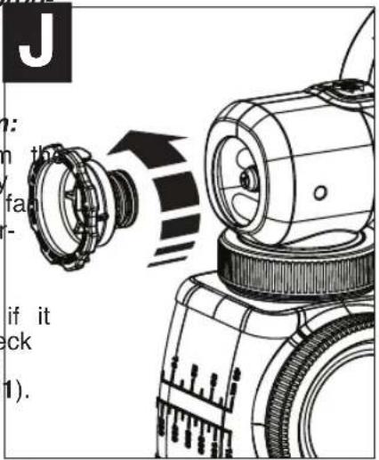
- Check that the sprayer is unplugged from power source. Remove the spray nozzle by turning counterclockwise (figure J). For the fa nozzle, remember to push and turn counterclockwise to remove.
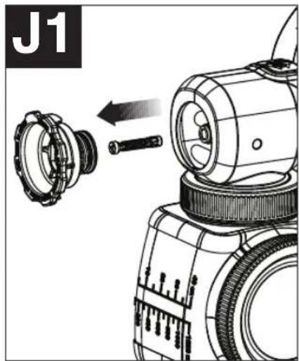
- Remove the atomizer and check to see if it needs to be cleaned or replaced. Also check inside the pump housing for any debris or obstruction and clean if necessary (figure J1).
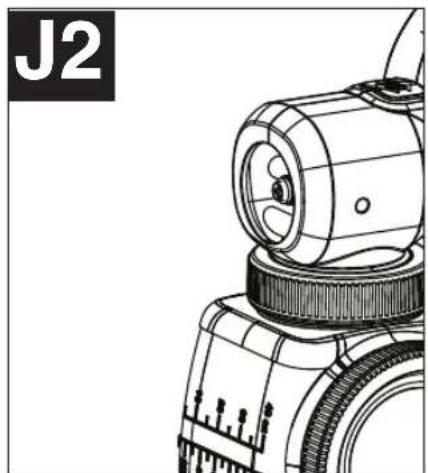
- Replace the atomizer valve making sure seats properly (figure J2).
- Thread the spray nozzle back onto the sprayer by turning clockwise (figure J3).
natural_image
Technical line drawing of a mechanical surveying instrument (no text or symbols visible)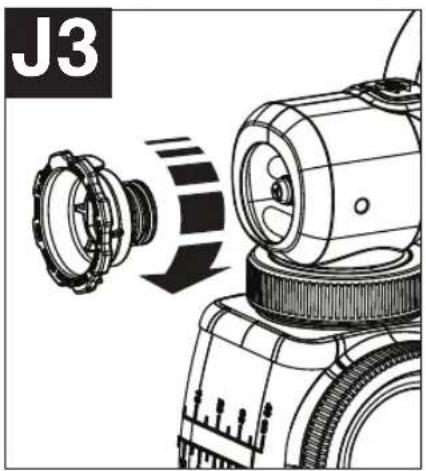
natural_image
Technical illustration of a mechanical device with a rotating component and directional arrow (no text or symbols)CLEANING
⚠ WARNING: Be sure to use appropriate protective gear.
• Make sure clean up area is well ventilated and free of flammable vapors.
• Always spray outdoors when spraying cleaning solution through sprayer.
- Use drop cloths during pouring, mixing, and viscosity testing of materials to be sprayed to protect your anything else in the spraying area that you wish to remain untouched.
TO BEGIN CLEANING:
- Unplug the sprayer from the power sou
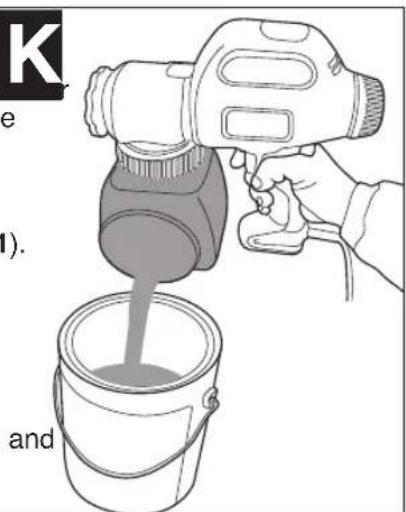
- Unscrew the lid from the side of the c and pour any remaining liquid back into the original container (figure K).
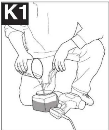
- Pour a small amount of the appropriate cleaning solution into the canister (figure K1).
- Warm soapy water for water based materials
• Manufacturers recommended cleaning solution for oil based materials
- Replace the lid on the canister securely vigorously shake the sprayer.
and
natural_image
Line drawing of a person pouring liquid from a container into a machine (no text or symbols)- Unscrew the lid from the side of the canister and properly dispose of cleaning solution.
-
Refill the canister with a small amount of new cleaning solution (figure K1). Screw lid securely on canister.
-
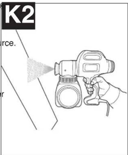
Plug in the cord and spray the cleaning solution through the sprayer onto scrap material for 5 seconds (figure K2).
- Unplug the sprayer from the power source.
• Properly dispose of cleaning solution. - Remove the spray nozzle, by turning counterclockwise, then remove the atomizer (figure K3). Refer to figures C & C1.
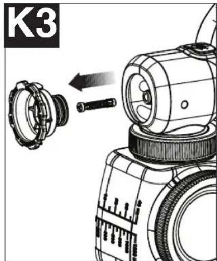
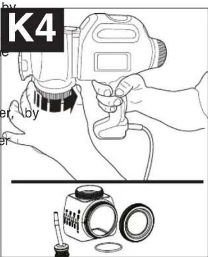
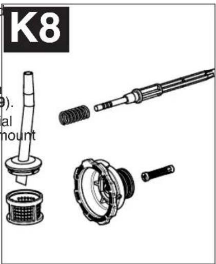
- Unscrew the canister from the sprayer turning the collar as shown in figure K4. Remove the pickup tube and filter and of from the sprayer. Clean the parts with the cleaning brush in the appropriate cleaning solution.
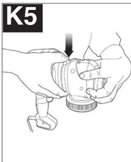
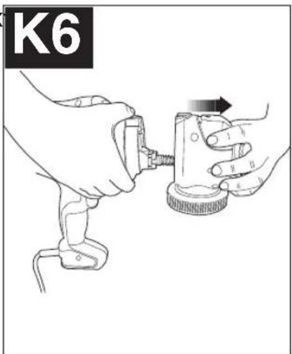
- Remove the front housing of the sprayer pressing down on the release button and pulling the front housing off of the sprayer (figure K5, K6).
natural_image
Illustration of hands using a mechanical tool to adjust a component (no text or symbols visible)- Remove the piston and spring (figure K)
natural_image
Illustration of hands using a tool to adjust or install a mechanical component (no text or symbols visible)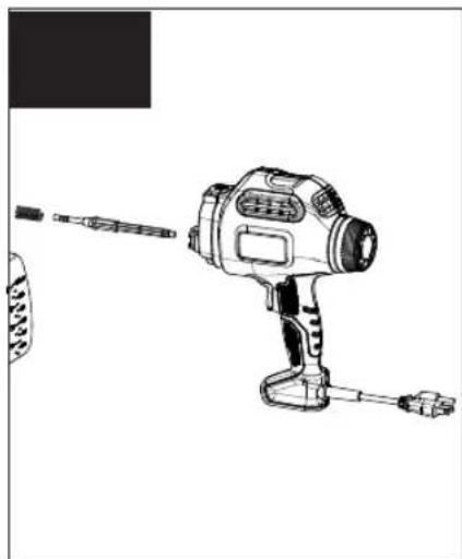
natural_image
Line drawing of a handheld electric drill with trigger and power cord (no text or symbols)- Clean the spray nozzle, pickup tube and filter, atomizer, piston and spring with the cleaning brush in the appropriate cleaning solution (figure K8).
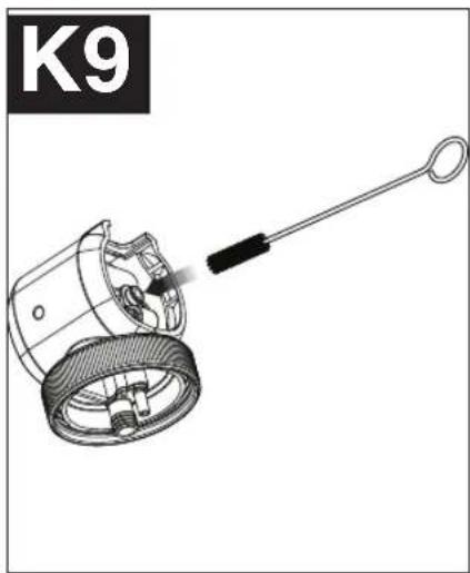
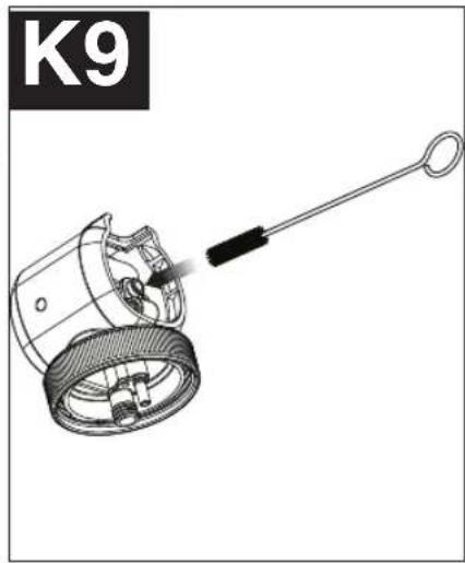
- Thoroughlyclean the inside of the piston chamber with the cleaning brush (figure K9).
IMPORTANT: Be sure to remove all material from inside of piston chamber. A small amount of material that is not removed with the cleaning brush can harden over time and interfere with the movement of the piston causing damage to the sprayer.
natural_image
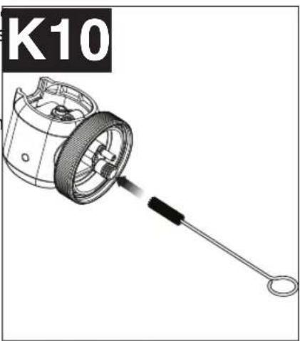
Technical illustration of a mechanical device with a lever and internal components (no text or symbols)- Thoroughly clean the inside of the intake and return openings with the cleaning brush (figure K10).
IMPORTANT: Also thoroughly clean the smaller vent hole, shown with an arrow in figure K11, with included cleaning pin.
- Dry all parts thoroughly.
natural_image
Technical illustration of a mechanical component with a tool and circular end (no text or symbols)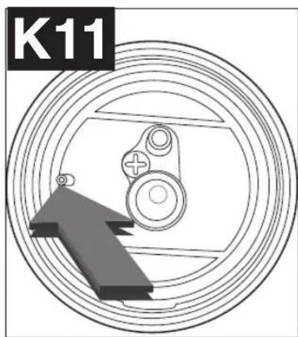
natural_image
Technical diagram of a mechanical component with concentric rings and a central gear-like structure, no visible text or symbols.REASSEMBLY
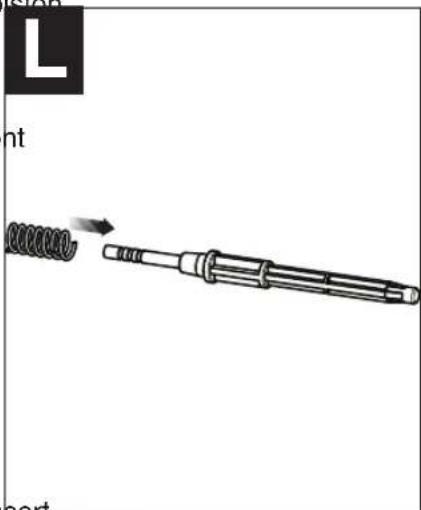
- Slide the spring onto the front of the piston (figure L).
-
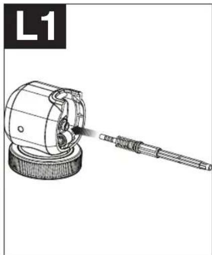
Insert the piston and spring into the front housing (figure L1).
-
Pressing down on the release button, insert the front housing with piston, into the sprat until the release button pops into place (figure L2).
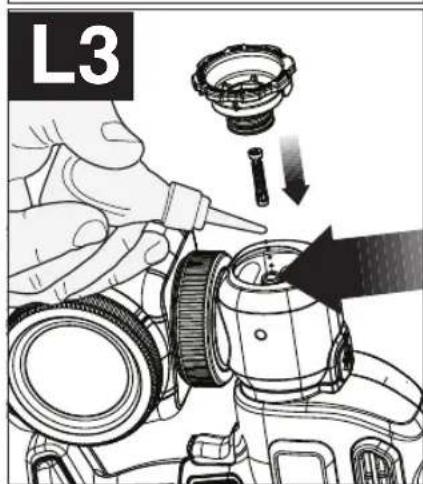
NOTICE: The unit will not reassemble without the piston and spring in place. - Place a few drops of oil through the cylinder opening. Insert the atomizer valve into the front housing. Thread the spray nozzle onto the front housing and hand tighten (figure L3).
natural_image
Technical illustration of a mechanical device with a tool emitting powder, labeled 'L1' in the corner (no text or symbols on the diagram itself)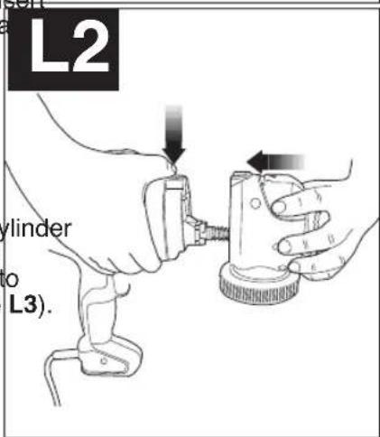
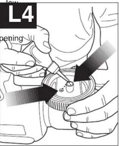
• Using the oil lubricant provided, place a drops of oil down the intake and return openings of the sprayer as shown in figu
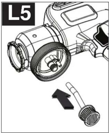
- Insert the pickup tube into the intake of on the sprayer (figure L5).
natural_image
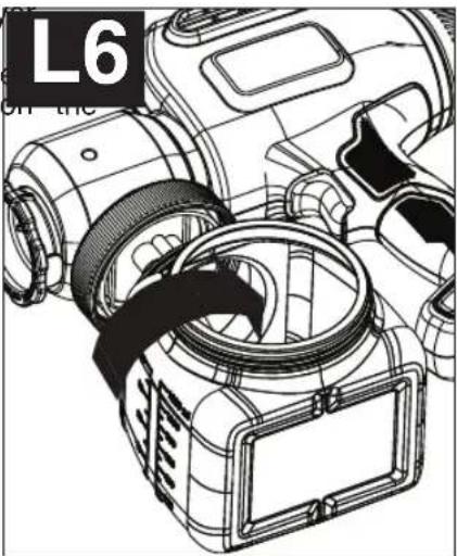
Technical illustration of a mechanical device with labeled part L5 and directional arrow (no text or symbols on the diagram itself)- Thread the canister back onto the spray (figure L6) making sure the tabs on the canister align with the tabs on the thread collar. The side fill lid should always be left side of the sprayer.
natural_image
Technical line drawing of a digital camera module with no visible text or symbolsMAINTENANCE
Use only mild soap and damp cloth to clean the power unit. Never let any liquid get inside the power immerse any part of the power unit into a liquid.
IMPORTANT: To assure product SAFETY and RELIABILITY, repairs, maintenance and adjustment (other than those listed in this manual) should be performed by authorized service centers or other qualified service organizations, always using identical replacement parts.
ACCESSORIES
Recommended accessories for use with your product are available from your local dealer or authorized site center. If you need assistance regarding accessories, please call: 1-800-544-6986

WARNING: The use of any accessory not recommended for use with this product could be hazardous.
SERVICE INFORMATION
All Black & Decker Service Centers are staffed with trained personnel to provide customers with efficient and reliable power tool service. Whether you need technical advice, repair, or genuine factory replacement parts, conta & Decker location nearest you. To find your local service location, refer to the yellow page directory unc "Tools—Electric" or call: 1-800-544-6986 or visit www.blackanddecker.com

WARNING: Tool service must be performed only by qualified repair personnel.

WARNING: When servicing a tool, use only identical replacement parts.
WARRANTY
Full Two-Year Home Use Warranty
Black & Decker (U.S.) Inc. warrants this product for two years against any defects in material or work made defective product will be replaced or repaired at no charge in either of two ways.
The first, which will result in exchanges only, is to return the product to the retailer from whom it was (provided that the store is a participating retailer). Returns should be made within the time period of the retailer's policy for exchanges (usually 30 to 90 days after the sale). Proof of purchase may be required. Please check for their specific return policy regarding returns that are beyond the time set for exchanges.
The second option is to take or send the product (prepaid) to a Black & Decker owned or authorized Service Center for repair or replacement at our option. Proof of purchase may be required. Black & Decker owned and auth Centers are listed under "Tools-Electric" in the yellow pages of the phone directory.
This warranty does not apply to accessories. This warranty gives you specific legal rights and you may rights which vary from state to state or province to province. Should you have any questions, contact the your nearest Black & Decker Service Center. This product is not intended for commercial use.
LATIN AMERICA: This warranty does not apply to products sold in Latin America. For products sold in Latin America, check country specific warranty information contained in the packaging, call the local company or see the warranty information.
FREE WARNING LABEL REPLACEMENT: If your warning labels become illegible or are missing, call 1-800-544-6986 for a free replacement.
TROUBLESHOOTING
Problem Possible Cause Possible Solution
| Material runs or drips • Spraying too much material. • Reduce air flow by turning flow control knob.Spraying too slowly. • Increase speed of application.Spraying too close. • Increase distance from surface.Viscosity too thin. • Check dilution recommendation. | |
| Too much over spray. • Sprayer too far from surface. • Reduce distance to surface.Too much material being sprayed. • Reduce flow by turning flow co knob clockwise. | |
| Little or no material being released. • Spray nozzle/tip clogged. • Clean nozzles.Pickup tube loose or clogged. • Check tube.Flow control knob setting too low. • Increase flow control setting.Material too thick. • Check viscosity recommendation. | |
| Material being sprayed is splattering. • Viscosity of material is too low.recommendation. • Thin material per manufacturer | |
| Sprayer pulsates. • Material in canister almost empty. • Refill canister. | |
| Liquid comes out side of canister. • Lid not on square or tight enough. • Remove lid and reattach squarely and evenly, then tighten cap securely.Paint on threads of canister and lid. • Clean threads on top and side canister and lid. | |
| Motor operates properly but does not spray. • Plugged or worn atomizer valve. • Clean or replace as needed.Atomizer valve missing. • Put in atomizer valve.Material too thick. • Thin material.Plugged spray tip. • Clean tip.Intake filter plugged. • Clean intake filter.Control knob needs adjusting.Worn piston. • Adjust knob.Clean and oil or replace | |
| Cannot reassemble unit. • Skipped an assembly step. • Insert spring and piston into the housing prior to reassembling.Press and hold the release button while reassembling. |
For assistance with your product, visit our website www.blackanddecker.com for the location of the service center nearest you or call the BLACK & DECKER help line at 1-800-544-6986.
natural_image
Simple line drawing of a dropper bottle with a stopper and cap, labeled with number 15 (no text or symbols on the bottle itself)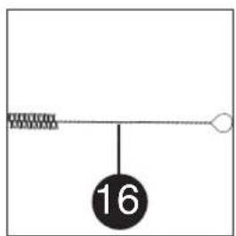
natural_image
Simple line drawing of a conical container with a handle and a dotted line indicating depth, labeled with number 17 (no text or symbols on the container itself)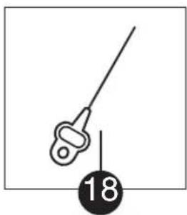
natural_image
Simple line drawing of a medical instrument with a labeled point '18' (no text or symbols on the instrument itself)PRÉPARATION

AVERTISSEMENT : S'assurer
natural_image
Technical line drawing of a mechanical component with no visible text or symbolsnatural_image
Technical line drawing of a mechanical device with a downward arrow indicating a component (no text or symbols present)PRÉPARATION DU PRODUIT LIQUIDE - (FIGURES E ET E1)
natural_image
Illustration of a person pouring liquid into a beaker (no text or symbols)
natural_image
Mechanical assembly diagram showing a rotating device with a gear-like component and directional arrow (no text or symbols)NETTOYAGE
natural_image
Technical illustration of a mechanical device with a lever and handle, labeled K9 (no text or symbols on the diagram itself)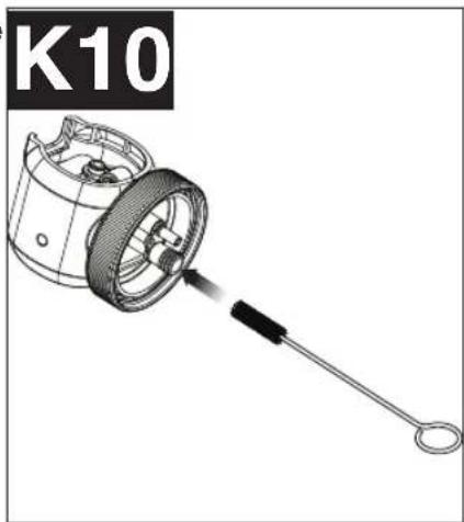
natural_image
Technical illustration of a mechanical component with a handle and circular end (no text or symbols)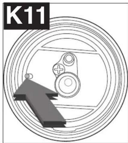
natural_image
Technical diagram of a mechanical component with concentric rings and a central gear-like structure, no text or symbols present.RÉASSEMBLAGE
natural_image
Diagram of a soldering iron with a spiral tip and shaft, showing motion direction (no text or symbols)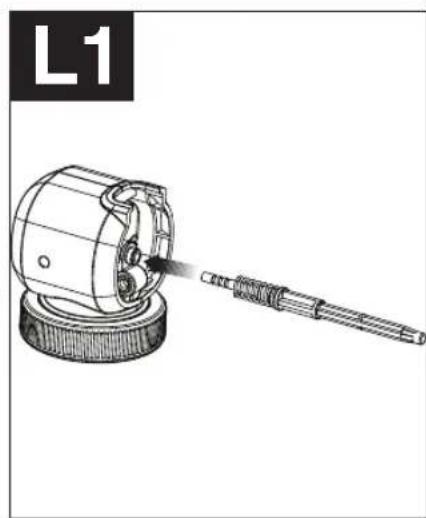
natural_image
Technical illustration of a mechanical device with a tool emitting motion, labeled 'L1' in the corner (no text or symbols on the diagram itself)natural_image
Technical illustration of a camera with a sensor and directional arrow (no text or symbols)natural_image
Technical line drawing of a camera module with no visible text or symbolsENTRETIEN
natural_image
Simple line drawing of a dropper bottle with a cap and tube, labeled with number 15 (no text or symbols on the bottle itself)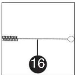
natural_image
Simple line drawing of a beaker with a pointed tip and a dotted line indicating depth, labeled with number 17 (no text or symbols on the object itself)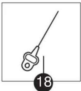
natural_image
Simple line drawing of a medical or surgical tool with a numbered label (18) below it, no text or symbols present.INSTALACIÓN
natural_image
Technical line drawing of a mechanical assembly with gears and shaft (no text or symbols)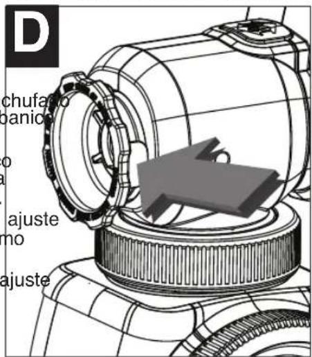
natural_image
Technical line drawing of a mechanical device with a downward arrow indicating a component (no text or symbols present)natural_image
Illustration of a person pouring liquid from a beaker into a container (no text or symbols)
natural_image
Line drawing of a hand holding a spray gun with a bottle, no text or symbols present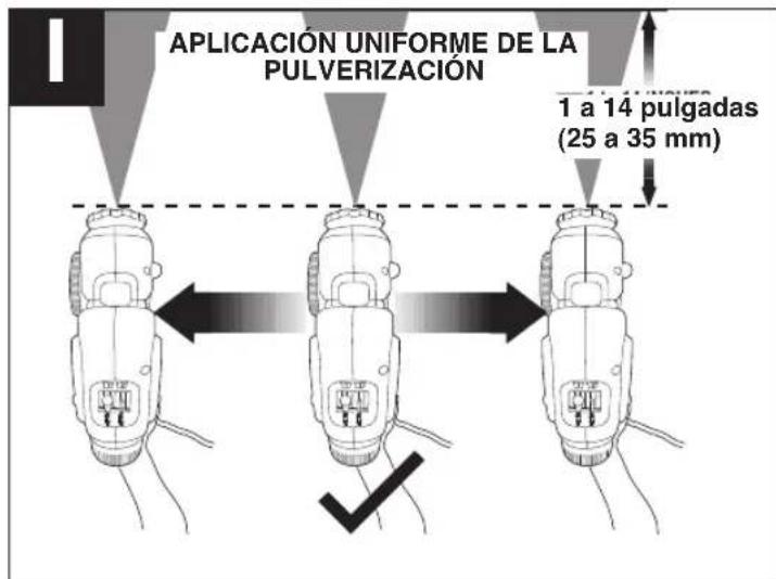
natural_image
Illustration of a person pouring liquid from a container into a tool, with no visible text or symbolsnatural_image
Technical illustration of a mechanical device with a close-up view of its internal components (no text or symbols)natural_image
Illustration of hands assembling a mechanical component (no text or symbols)natural_image
Illustration of hands using a tool to adjust or install a mechanical component (no text or symbols visible)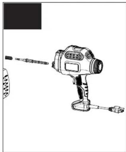
natural_image
Line drawing of a handheld electric shaver with a pointed tip and attached base (no text or symbols)natural_image
Technical illustration of a mechanical device with a lever and handle, labeled K9 (no text or symbols on the diagram itself)natural_image
Technical illustration of a mechanical component with a tool, labeled K10 (no text or symbols on the diagram itself)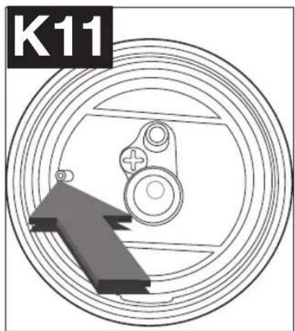
natural_image
Technical diagram of a mechanical component with concentric rings and a central gear-like structure (no text or symbols)REENSAMBLAJE
natural_image
Technical illustration of a mechanical device with a tool inserted, labeled 'L1' in the top-left corner (no other text or symbols)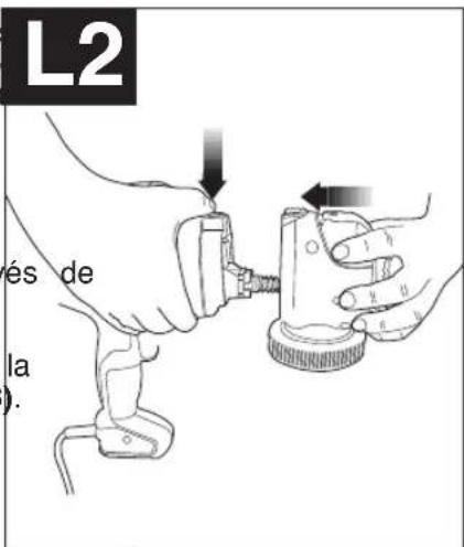
natural_image
Technical illustration of a camera with labeled parts and directional arrows (no text or symbols)Col. Fracc. Universidad
Chihuahua, Chihuahua
Tel. 01 614 413 64 04
Fernando González Armenta
Bolivia No. 605
Col. Felipe Carrillo Puerto
Cd. Madero, Tampico
Tel. 01 833 221 34 50
Date of purchase · Fecha de compra Invoice No. · No. de factura
- PLEASE READ BEFORE RETURNING THIS PRODUCT FOR ANY REASO
- SAFETY GUIDELINES - DEFINITIONS
- IMPORTANT SAFETY INSTRUCTIONS
- To avoid these risks, take the following preventions
- GENERAL SAFETY WARNINGS
- To avoid these risks, take the following preventions:
- GROUNDING INSTRUCTIONS
- EXTENSION CORDS
- COMPONENTS
- A
- FUNCTIONAL DESCRIPTION
- SET-UP
- SELECTING THE PROPER SPRAY
- NOZZLE - (FIGURES B AND B1)
- ATTACHING THE SPRAY NOZZLES - (FIGURES C AND C1)
- To attach the green fan spray nozzle:
- To remove the green fan spray nozzle:
- To attach the blue cone spray nozzle:
- ADJUSTING THE FAN SPRAY NOZZLE - (FIGURES D AND D1)
- To adjust the fan spray nozzle:
- LIQUID MATERIAL PREPARATION - (FIGURES E, E1)
- PREPARATION TIPS
- FILLING THE CANISTER - (FIGURE F)
- FLOW CONTROL SETTINGS
- FLOW CONTROL KNOB - (FIGURE G)
- OPERATION
- ON / OFF TRIGGER - (FIGURE H)
- DEVELOPING THE PROPER SPRAYING TECHNIQUE
- CLEANING
- TO BEGIN CLEANING:
- REASSEMBLY
- MAINTENANCE
- ACCESSORIES
- SERVICE INFORMATION
- WARRANTY
- Full Two-Year Home Use Warranty
- TROUBLESHOOTING
- PRÉPARATION
- PRÉPARATION DU PRODUIT LIQUIDE - (FIGURES E ET E1)
- NETTOYAGE
- RÉASSEMBLAGE
- ENTRETIEN
- INSTALACIÓN
- REENSAMBLAJE
Brand : BLACK & DECKER
Model : BDPS200
Category : Peinture en spray