
G 14DSL - Grinder HiKOKI - Free user manual and instructions
Find the device manual for free G 14DSL HiKOKI in PDF.


| Product type | Cordless angle grinder |
| Brand | HiKOKI |
| Model | G 14DSL |
| Voltage | 14.4 V |
| Battery type | Removable lithium-ion |
| Battery capacity | 3.0 Ah (standard) |
| Disc diameter | 100 mm |
| No-load speed | 8,500 rpm |
| Power consumption | 350 W |
| Weight (with battery) | 1.5 kg |
| Dimensions (L x W x H) | 250 x 70 x 100 mm |
| Power supply | 14.4 V Li-ion battery |
| Main functions | Cutting, grinding, deburring |
| Maintenance and cleaning | Clean ventilation slots with a brush |
| Safety | Disc brake, variable speed, adjustable protective guard |
| Spare parts and repairability | Motor brushes, battery, discs, guard available |
| General information | 2-year warranty, professional use |
Frequently Asked Questions - G 14DSL HiKOKI
User questions about G 14DSL HiKOKI
0 question about this device. Answer the ones you know or ask your own.
Ask a new question about this device
Download the instructions for your Grinder in PDF format for free! Find your manual G 14DSL - HiKOKI and take your electronic device back in hand. On this page are published all the documents necessary for the use of your device. G 14DSL by HiKOKI.
USER MANUAL G 14DSL HiKOKI
G 14DSL · G 18DSL · G 18DSL(S)
natural_image
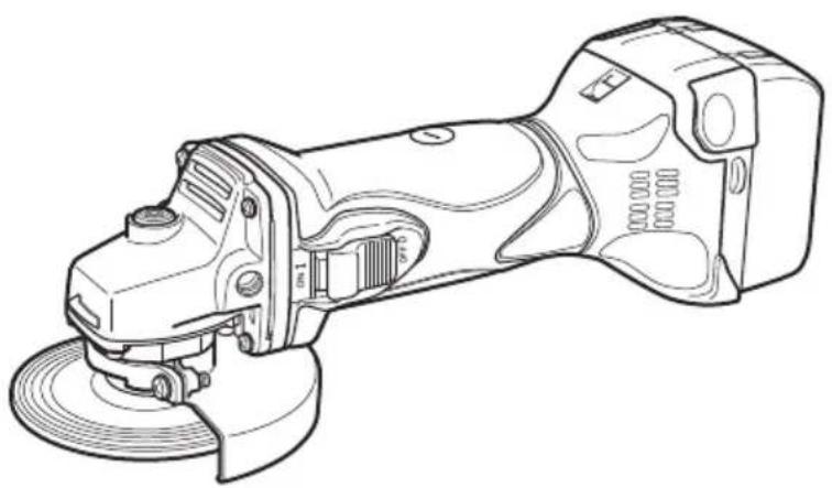
Line drawing of a mechanical power tool with angular base and side buttons (no text or symbols)G14DSL

en Handling instructions
de Bedienungsanleitung
fr Mode d'emploi
it Istruzioni per l'uso
nl Gebruiksaanwijzing
es Instrucciones de manejo
pt Instruções de uso
sv Bruksanvisning
da Brugsanvisning
no Bruksanvisning
fi Käyttöohjeet
el Οδηγίες χειρισμού
pl Instrukcja obsługi
hu Kezelési utasítás
cs Návod k obsluze
tr Kullanım talimatları
ro Instructiuni de utilizare
sl Navodila za rokovanje
sk Pokyny na manipuláciu
bg Инструкция за експлоатация
sr Uputstvo za rukovanje
hr Upute za rukovanje
UK Інструкції щодо поводження з пристроєм
ru Инструкция по эксплуатации
(Original instructions)
GENERAL POWER TOOL SAFETY WARNINGS

WARNING
Read all safety warnings and all instructions.
Failure to follow the warnings and instructions may result in electric shock, fi re and/or serious injury.
Save all warnings and instructions for future reference.
The term “power tool” in the warnings refers to your mains-operated (corded) power tool or battery-operated (cordless) power tool.
1) Work area safety
a) Keep work area clean and well lit.
Cluttered or dark areas invite accidents.
b) Do not operate power tools in explosive atmospheres, such as in the presence of fl ammable liquids, gases or dust.
Power tools create sparks which may ignite the dust or fumes.
c) Keep children and bystanders away while operating a power tool.
Distractions can cause you to lose control.
2) Electrical safety
a) Power tool plugs must match the outlet.
Never modify the plug in any way.
Do not use any adapter plugs with earthed (grounded) power tools.
Unmodified plugs and matching outlets will reduce risk of electric shock.
b) Avoid body contact with earthed or grounded surfaces, such as pipes, radiators, ranges and refrigerators. There is an increased risk of electric shock if your body is earthed or grounded.
c) Do not expose power tools to rain or wet conditions. Water entering a power tool will increase the risk of electric shock.
d) Do not abuse the cord. Never use the cord for carrying, pulling or unplugging the power tool. Keep cord away from heat, oil, sharp edges or moving parts.
Damaged or entangled cords increase the risk of electric shock.
e) When operating a power tool outdoors, use an extension cord suitable for outdoor use.
Use of a cord suitable for outdoor use reduces the risk of electric shock.
f) If operating a power tool in a damp location is unavoidable, use a residual current device (RCD) protected supply.
Use of an RCD reduces the risk of electric shock.
3) Personal safety
a) Stay alert, watch what you are doing and use common sense when operating a power tool.
Do not use a power tool while you are tired or under the influence of drugs, alcohol or medication.
A moment of inattention while operating power tools may result in serious personal injury.
b) Use personal protective equipment. Always wear eye protection.
Protective equipment such as dust mask, non-skid safety shoes, hard hat, or hearing protection used for appropriate conditions will reduce personal injuries.
c) Prevent unintentional starting. Ensure the switch is in the off position before connecting to power source and/or battery pack, picking up or carrying the tool.
Carrying power tools with your fi nger on the switch or energising power tools that have the switch on invites accidents.
d) Remove any adjusting key or wrench before turning the power tool on.
A wrench or a key left attached to a rotating part of the power tool may result in personal injury.
e) Do not overreach. Keep proper footing and balance at all times.
This enables better control of the power tool in unexpected situations.
f) Dress properly. Do not wear loose clothing or jewellery. Keep your hair, clothing and gloves away from moving parts.
Loose clothes, jewellery or long hair can be caught in moving parts.
g) If devices are provided for the connection of dust extraction and collection facilities, ensure these are connected and properly used.
Use of dust collection can reduce dust-related hazards.
4) Power tool use and care
a) Do not force the power tool. Use the correct power tool for your application.
The correct power tool will do the job better and safer at the rate for which it was designed.
b) Do not use the power tool if the switch does not turn it on and off.
Any power tool that cannot be controlled with the switch is dangerous and must be repaired.
c) Disconnect the plug from the power source and/or the battery pack from the power tool before making any adjustments, changing accessories, or storing power tools.
Such preventive safety measures reduce the risk of starting the power tool accidentally.
d) Store idle power tools out of the reach of children and do not allow persons unfamiliar with the power tool or these instructions to operate the power tool.
Power tools are dangerous in the hands of untrained users.
e) Maintain power tools. Check for misalignment or binding of moving parts, breakage of parts and any other condition that may affect the power tool's operation.
If damaged, have the power tool repaired before use.
Many accidents are caused by poorly maintained power tools.
f) Keep cutting tools sharp and clean.
Properly maintained cutting tools with sharp cutting edges are less likely to bind and are easier to control.
g) Use the power tool, accessories and tool bits etc. in accordance with these instructions, taking into account the working conditions and the work to be performed.
Use of the power tool for operations different from those intended could result in a hazardous situation.
5) Battery tool use and care
a) Recharge only with the charger specified by the manufacturer.
A charger that is suitable for one type of battery pack may create a risk of fi re when used with another battery pack.
b) Use power tools only with specifically designated battery packs.
Use of any other battery packs may create a risk of injury and fire.
c) When battery pack is not in use, keep it away from other metal objects, like paper clips, coins, keys, nails, screws or other small metal objects, that can make a connection from one terminal to another.
Shorting the battery terminals together may cause burns or a fire.
d) Under abusive conditions, liquid may be ejected from the battery; avoid contact. If contact accidentally occurs, fl ush with water. If liquid contacts eyes, additionally seek medical help.
Liquid ejected from the battery may cause irritation or burns.
6) Service
a) Have your power tool serviced by a qualified repair person using only identical replacement parts.
This will ensure that the safety of the power tool is maintained.
PRECAUTION
Keep children and infi rm persons away.
When not in use, tools should be stored out of reach of children and infi rm persons.
SAFETY WARNINGS COMMON FOR GRINDING OR ABRASIVE CUTTING-OFF OPERATIONS
a) This power tool is intended to function as a grinder or cut-off tool. Read all safety warnings, instructions, illustrations and specifications provided with this power tool.
Failure to follow all instructions listed below may result in electric shock, fire and/or serious injury.
b) Operations such as sanding, wire brushing or polishing are not recommended to be performed with this power tool.
Operations for which the power tool was not designed may create a hazard and cause personal injury.
c) Do not use accessories which are not specifically designed and recommended by the tool manufacturer.
Just because the accessory can be attached to your power tool, it does not assure safe operation.
d) The rated speed of the accessory must be at least equal to the maximum speed marked on the power tool.
Accessories running faster than their rated speed can break and fly apart.
e) The outside diameter and the thickness of your accessory must be within the capacity rating of your power tool.
Incorrectly sized accessories cannot be adequately guarded or controlled.
f) Threaded mounting of accessories must match the grinder spindle thread. For accessories mounted by flanges, the arbour hole of the accessory must fit the locating diameter of the flange.
Accessories that do not match the mounting hardware of the power tool will run out of balance, vibrate excessively and may cause loss of control.
g) Do not use a damaged accessory. Before each use inspect the accessory such as abrasive wheels for chips and cracks, backing pad for cracks, tear or excess wear, wire brush for loose or cracked wires. If power tool or accessory is dropped, inspect for damage or install an undamaged accessory. After inspecting and installing an accessory, position yourself and bystanders away from the plane of the rotating accessory and run the power tool at maximum no-load speed for one minute.
Damaged accessories will normally break apart during this test time.
h) Wear personal protective equipment. Depending on application, use face shield, safety goggles or safety glasses. As appropriate, wear dust mask, hearing protectors, gloves and workshop apron capable of stopping small abrasive or workpiece fragments.
The eye protection must be capable of stopping flying debris generated by various operations. The dust mask or respirator must be capable of filtrating particles generated by your operation. Prolonged exposure to high intensity noise may cause hearing loss.
i) Keep bystanders a safe distance away from work area. Anyone entering the work area must wear personal protective equipment.
Fragments of workpiece or of a broken accessory may fly away and cause injury beyond immediate area of operation.
j) Hold the power tool by insulated gripping surfaces only, when performing an operation where the cutting tool may contact hidden wiring.
Contact with a "live" wire will also make exposed metal parts of the power tool "live" and could give the operator an electric shock.
k) Position the cord clear of the spinning accessory.
If you lose control, the cord may be cut or snagged and your hand or arm may be pulled into the spinning accessory.
I) Never lay the power tool down until the accessory has come to a complete stop.
The spinning accessory may grab the surface and pull the power tool out of your control.
m) Do not run the power tool while carrying it at your side.
Accidental contact with the spinning accessory could snag your clothing, pulling the accessory into your body.
n) Regularly clean the power tool's air vents.
The motor's fan will draw the dust inside the housing and excessive accumulation of powdered metal may cause electrical hazards.
o) Do not operate the power tool near flammable materials.
Sparks could ignite these materials.
p) Do not use accessories that require liquid coolants.
Using water or other liquid coolants may result in electrocution or shock.
KICKBACK AND RELATED WARNINGS
Kickback is a sudden reaction to a pinched or snagged rotating wheel, backing pad, brush or any other accessory. Pinching or snagging causes rapid stalling of the rotating accessory which in turn causes the uncontrolled power tool to be forced in the direction opposite of the accessory's rotation at the point of the binding.
For example, if an abrasive wheel is snagged or pinched by the workpiece, the edge of the wheel that is entering into the pinch point can dig into the surface of the material causing the wheel to climb out or kick out. The wheel may either jump
English
toward or away from the operator, depending on direction of the wheel's movement at the point of pinching.
Abrasive wheels may also break under these conditions.
Kickback is the result of power tool misuse and/or incorrect operating procedures or conditions and can be avoided by taking proper precautions as given below.
a) Maintain a firm grip on the power tool and position your body and arm to allow you to resist kickback forces. Always use auxiliary handle, if provided, for maximum control over kickback or torque reaction during start-up.
The operator can control torque reactions or kickback forces, if proper precautions are taken.
b) Never place your hand near the rotating accessory. Accessory may kickback over your hand.
c) Do not position your body in the area where power tool will move if kickback occurs.
Kickback will propel the tool in direction opposite to the wheel's movement at the point of snagging.
d) Use special care when working corners, sharp edges etc. Avoid bouncing and snagging the accessory.
Corners, sharp edges or bouncing have a tendency to snag the rotating accessory and cause loss of control or kickback.
e) Do not attach a saw chain woodcarving blade or toothed saw blade.
Such blades create frequent kickback and loss of control.
SAFETY WARNINGS SPECIFIC FOR GRINDING AND ABRASIVE CUTTING-OFF OPERATIONS
a) Use only wheel types that are recommended for your power tool and the specific guard designed for the selected wheel.
Wheels for which the power tool was not designed cannot be adequately guarded and are unsafe.
b) The grinding surface of centre depressed wheels must be mounted below the plane of the guard lip.
An improperly mounted wheel that projects through the plane of the guard lip cannot be adequately protected.
c) The guard must be securely attached to the power tool and positioned for maximum safety, so the least amount of wheel is exposed towards the operator.
The guard helps to protect the operator from broken wheel fragments, accidental contact with wheel and sparks that could ignite clothing.
d) Wheels must be used only for recommended applications. For example: do not grind with the side of cut-off wheel.
Abrasive cut-off wheels are intended for peripheral grinding, side forces applied to these wheels may cause them to shatter.
e) Always use undamaged wheel fl anges that are of correct size and shape for your selected wheel.
Proper wheel flanges support the wheel thus reducing the possibility of wheel breakage. Flanges for cut-off wheels may be different from grinding wheel flanges.
f) Do not use worn down wheels from larger power tools.
Wheel intended for larger power tool is not suitable for the higher speed of a smaller tool and may burst.
ADDITIONAL SAFETY WARNINGS SPECIFIC FOR ABRASIVE CUTTING- OFF OPERATIONS
a) Do not "jam" the cut-off wheel or apply excessive pressure. Do not attempt to make an excessive depth of cut.
Overstressing the wheel increases the loading and susceptibility to twisting or binding of the wheel in the cut and the possibility of kickback or wheel breakage.
b) Do not position your body in line with and behind the rotating wheel.
When the wheel, at the point of operation, is moving away from your body, the possible kickback may propel the spinning wheel and the power tool directly at you.
c) When wheel is binding or when interrupting a cut for any reason, switch off the power tool and hold the power tool motionless until the wheel comes to a complete stop. Never attempt to remove the cut-off wheel from the cut while the wheel is in motion otherwise kickback may occur.
Investigate and take corrective action to eliminate the cause of wheel binding.
d) Do not restart the cutting operation in the workpiece. Let the wheel reach full speed and carefully re-enter the cut.
The wheel may bind, walk up or kickback if the power tool is restarted in the workpiece.
e) Support panels or any oversized workpiece to minimize the risk of wheel pinching and kickback.
Large workpieces tend to sag under their own weight. Supports must be placed under the workpiece near the line of cut and near the edge of the workpiece on both sides of the wheel.
f) Use extra caution when making a "pocket cut" into existing walls or other blind areas.
The protruding wheel may cut gas or water pipes, electrical wiring or objects that can cause kickback.
ADDITIONAL SAFETY WARNINGS
- Always use eye and ear protection. Other personal protective equipment such as dust mask, gloves, helmet and apron should be worn.
- Preparing and checking the work environment. Make sure that the work site meets all the conditions laid forth in the precautions.
- Check that the work piece is properly supported.
- Confir rm that the depressed center wheel is mounted firmly.
- Check that speed marked on the wheel is equal to or greater than the rated speed of the grinder.
- Ensure that the wheel dimensions are compatible with the grinder.
- Ensure that the wheel guard is properly fitted and fastened before commencing grinding operation.
- Abrasive wheels shall be stored and handled with care in accordance with manufacturer's instructions.
- Inspect the grinding wheel before use, do not use cing chipped, cracked or otherwise defective products.
- Ensure that mounted wheels and points are fitted in accordance with the manufacturer's instructions.
- Ensure that blotters are used when they are provided with the bonded abrasive product and when they are required.
-
Ensure that the abrasive product is correctly mounted and tightened before use and run the tool at no-load for 30 seconds in a safe position, stop immediately if there is considerable vibration or if other defects are detected. If this condition occurs, check the machine to determine the cause.
-
If a guard is equipped with the tool never use the tool without such a guard.
- Do not use separate reducing bushings or adapters to adapt large hole abrasive wheels.
- For tools intended to be fitted with threaded hole wheel, ensure that the thread in the wheel is long enough to accept the spindle length.
- Do not use cutting off wheel for side grinding.
- Ensure that sparks resulting from use do not create a hazard e.g. do not hit persons, or ignite flammable substances.
- Ensure that ventilation openings are kept clear when working in dusty conditions, if it should become necessary to clear dust, fi rst disconnect the tool from the mains supply (use non metallic objects) and avoid damaging internal parts.
- Pay attention to the wheel that continues to rotate after the tool is switched off. After switching off the machine, do not put it down until the depressed center wheel has come to a complete stop. Apart from avoiding serious accidents, this precaution will reduce the amount of dust and swarf sucked into the machine.
- Be sure to turn off the switch and pull out the battery to avoid a serious accident before the depressed center wheel is assembling and disassembling.
- To prolong the life of the machine and ensure a first class fi nish, it is important that the machine should not be overloaded by applying too much pressure. In most applications, the weight of the machine alone is suffi cient for eff ective grinding. Too much pressure will result in reduced rotational speed, inferior surface finish, and overloading which could reduce the life of the machine.
- Ensure that fixing the side handle into the gear cover securely.
- Confirm that the spindle lock button is disengaged by pushing spindle lock button two or three times before switching the power tool on. (See Fig. 6, 7)
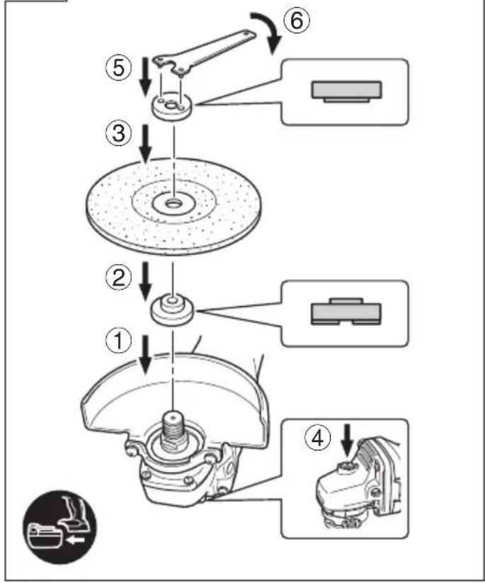
- Ensure that the depressed center wheel to be utilized is the correct type and free of cracks or surface defects. Also ensure that the depressed center wheel is properly mounted and the wheel nut is securely tightened.
- Actuate the spindle lock button only when the tool is at a standstill.
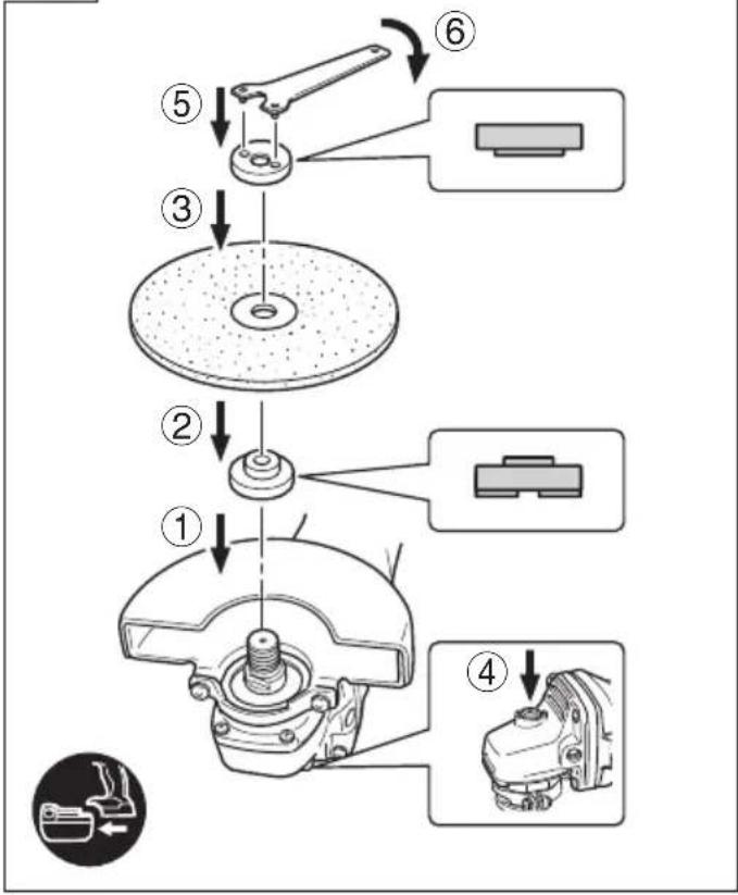
- Use cutting wheel (for G14DSL / G18DSL)
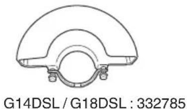
When using a abrasive cutting wheel, be sure to remove the standard accessory wheel guard and attach the WHEEL GUARD (FOR CUTTING) with side guard (sold separately). (Fig. 7) - Secure the workpiece. A workpiece clamped with clamping devices or in a vice is held more secure than by hand.
- Make sure that the battery is installed firmly. If it is at all loose it could come off and cause an accident.
- When the machine is not use, the battery should be disconnected.
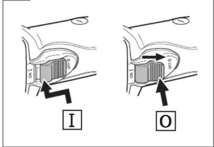
- To prevent injuries, this product has a function that prevents unexpected motor rotation when the battery is inserted. The motor will not run if the battery is inserter while the switch is still ON. After installing the battery, turn the switch off and then back on again.
- The G14DSL / G18DSL / G18DSL(S) models are equipped with a protection function that will shut down the tool in the event of an overload.
Should the tool shut down due to an overload, turn the power off and then turn it back on again. - Do not allow foreign matter to enter the hole for connecting the rechargeable battery.
- Never disassemble the rechargeable battery and charger.
-
Never short-circuit the rechargeable battery. Shortcircuiting the battery will cause a great electric current and overheat. It results in burn or damage to the battery.
-
Do not dispose of the battery in fire. If the battery is burnt, it may explode.
- Do not insert object into the air ventilation slots of the charger. Inserting metal objects or inflammables into the charger air ventilation slots will result in electrical shock hazard or damaged charger.
- Bring the battery to the shop from which it was purchased as soon as the post-charging battery life becomes too short for practical use. Do not dispose of the exhausted battery.
CAUTION ON LITHIUM-ION BATTERY
To extend the lifetime, the lithium-ion battery equips with the protection function to stop the output.
In the cases of 1 to 3 described below, when using this product, even if you are pulling the switch, the motor may stop. This is not the trouble but the result of protection function.
- When the battery power remaining runs out, the motor stops.
In such a case, charge it up immediately. - If the tool is overloaded, the motor may stop. In this case, release the switch of tool and eliminate causes of overloading. After that, you can use it again.
- If the battery is overheated under overload work, the battery power may stop.
In this case, stop using the battery and let the battery cool. After that, you can use it again.
Furthermore, please heed the following warning and caution. WARNING
In order to prevent any battery leakage, heat generation, smoke emission, explosion and ignition beforehand, please be sure to heed the following precautions.
- Make sure that swarf and dust do not collect on the battery.
During work make sure that swarf and dust do not fall on the battery.
○ Make sure that any swarf and dust falling on the power tool during work do not collect on the battery. - Do not store an unused battery in a location exposed to swarf and dust.
Before storing a battery, remove any swarf and dust that may adhere to it and do not store it together with metal parts (screws, nails, etc.). - Do not pierce battery with a sharp object such as a nail, strike with a hammer, step on, throw or subject the battery to severe physical shock.
- Do not use an apparently damaged or deformed battery.
- Do not use the battery in reverse polarity.
- Do not connect directly to an electrical outlets or car cigarette lighter sockets.
- Do not use the battery for a purpose other than those specified.
- If the battery charging fails to complete even when a specified recharging time has elapsed, immediately stop further recharging.
- Do not put or subject the battery to high temperatures or high pressure such as into a microwave oven, dryer, or high pressure container.
- Keep away from fi re immediately when leakage or foul odor are detected.
- Do not use in a location where strong static electricity generates.
- If there is battery leakage, foul odor, heat generated, discolored or deformed, or in any way appears abnormal during use, recharging or storage, immediately remove it from the equipment or battery charger, and stop use.
English
CAUTION
- If liquid leaking from the battery gets into your eyes, do not rub your eyes and wash them well with fresh clean water such as tap water and contact a doctor immediately.
If left untreated, the liquid may cause eye-problems.
- If liquid leaks onto your skin or clothes, wash well with clean water such as tap water immediately.
There is a possibility that this can cause skin irritation.
- If you find rust, foul odor, overheating, discolor, deformation, and/or other irregularities when using the battery for the first time, do not use and return it to your supplier or vendor.
WARNING
If a conductive foreign matter enters in the terminal of lithium ion battery, the battery may be shorted, causing fire. When storing the lithium ion battery, obey surely the rules of following contents.
- Do not place conductive debris, nail and wires such as iron wire and copper wire in the storage case.
To prevent shorting from occurring, load the battery in the tool or insert securely the battery cover for storing until the ventilator is not seen.
SYMBOLS
WARNING
The following show symbols used for the machine.
Be sure that you understand their meaning before use.
| G14DSL / G18DSL / G18DSL(S): Cordless Disc Grinder | |
| Read all safety warnings and all instructions. | |
| Always wear eye protection. | |
| Only for EU countriesDo not dispose of electric tools together with household waste material!In observance of European Directive 2002/96/EC on waste electrical and electronic equipment and its implementation in accordance with national law, electric tools that have reached the end of their life must be collected separately and returned to an environmentally compatible recycling facility. | |
| V Rated voltage | |
| n | Rated speed |
| min ^-1 | Revolution or reciprocations per minute |
| D Wheel outer diameter | |
| d Wheel hole diameter | |
| t Wheel thickness | |
| Peripheral speed | |
| Weight | |
| Switching ON | |
| Switching OFF | |
| Disconnect the battery | |
| Battery capacity | |
| The battery remaining power is nearly empty. Recharge the battery soonest possible | |
| The battery remaining power is a half. | |
| The battery remaining power is enough. |
STANDARD ACCESSORIES
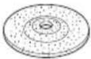
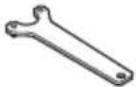
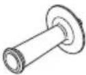
In addition to the main unit (1 unit), the package contains the accessories listed on page 187.
Standard accessories are subject to change without notice.
APPLICATIONS
○ Removal of casting fin and finishing of various types of steel, bronze and aluminum materials and castings.
- Grinding of welded sections or sections cut by means of a cutting torch.
○ Grinding of synthetic resins, slate, brick, marble, etc.
○ Cutting of synthetic concrete, stone, brick, marble, and similar materials.
SPECIFICATIONS
The specifications of this machine are listed in the Table on page 187.
NOTE
Due to HiKOKI's continuing program of research and development, the specifications herein are subject to change without prior notice.
CHARGING
Before using the power tool, charge the battery as follows.
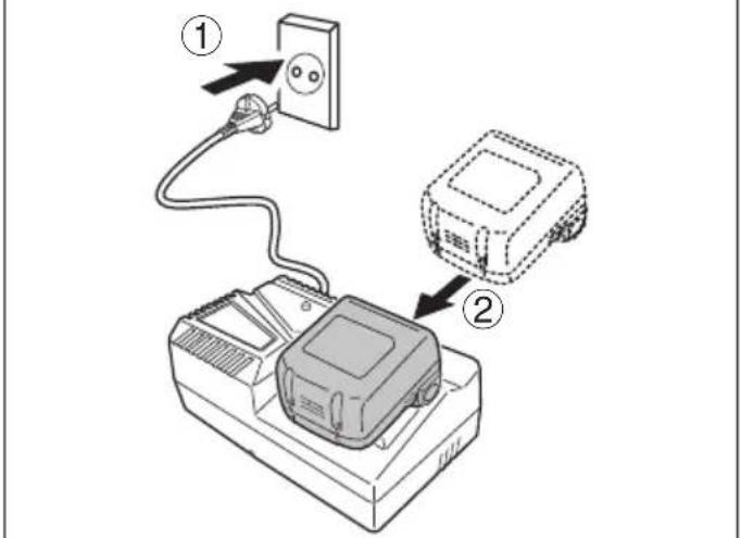
- Connect the charger's power cord to the receptacle.
When connecting the plug of the charger to a receptacle, the pilot lamp will blink in red (At 1-second intervals).
CAUTION
Do not use the electrical cord if damaged. Have it repaired immediately.
- Insert the battery into the charger.
Firmly insert the battery into the charger as shown in Fig. 1.
- Charging
When inserting a battery in the charger, charging will commence and the pilot lamp will light continuously in red.
When the battery becomes fully recharged, the pilot lamp will blink in red. (At 1-second intervals) (See Table 1)
● Pilot lamp indication
The indications of the pilot lamp will be as shown in Table 1, according to the condition of the charger or the rechargeable battery.
Table 1
| Indications of the pilot lamp | ||||
| Pilot lamp(red) | Before charging | Blinks | Lights for 0.5 seconds. Does not light for 0.5 seconds. (off for 0.5 seconds) | |
| While charging Lights | Lights continuously | |||
| Charging complete | Blinks | Lights for 0.5 seconds. Does not light for 0.5 seconds. (off for 0.5 seconds) | ||
| Overheat standby | Blinks | Lights for 1 second. Does not light for 0.5 seconds. (off for 0.5 seconds) | Battery overheated. Unable to charge. (Charging will commence when battery cools) | |
| Charging impossible | Flickers | Lights for 0.1 seconds. Does not light for 0.1 seconds. (off for 0.1 seconds) | Malfunction in the battery or the charger | |
- Regarding the temperatures and charging time of the battery. The temperatures and charging time will become as shown in Table 2.
Table 2
| Battery\Charger | UC18YFSL | |
| Charging voltage | V | 14.4 – 18 |
| Weight | kg | 0.5 |
| Temperatures at which the battery can be recharged | 0°C – 50°C | |
| Charging time for battery capacity, approx. (At 20°C) | ||
| 1.3 Ah | min. | 20 |
| 1.5 Ah | min. | 22 |
| 2.0 Ah | min. | 30 |
| 2.5 Ah | min. | 35 |
| 3.0 Ah | min. | 45 |
| 4.0 Ah | min. | 60 |
| 5.0 Ah | min. | 75 |
| Number of battery cells | 4 – 10 | |
NOTE
The recharging time may vary according to the ambient temperature and power source voltage.
CAUTION
When the battery charger has been continuously used, the battery charger will be heated, thus constituting the cause of the failures. Once the charging has been completed, give 15 minutes rest until the next charging.
4. Disconnect the charger's power cord from the receptacle.
5. Hold the charger firmly and pull out the battery.
NOTE
Be sure to pull out the battery from the charger after use, and then keep it.
CAUTION
☐ If the battery is charged while it is heated because it has been left for a long time in a location subject to direct sunlight or because the battery has just been used, the pilot lamp of the charger lights for 1 second, does not light for 0.5 seconds (off for 0.5 seconds). In such a case, first let the battery cool, then start charging.
When the pilot lamp flickers (at 0.2-second intervals), check for and take out any foreign objects in the charger's battery connector. If there are no foreign objects, it is probable that the battery or charger is malfunctioning. Take it to your authorized Service Center.
○ Since the built-in micro computer takes about 3 seconds to confirm that the battery being charged with charger is taken out, wait for a minimum of 3 seconds before reinserting it to continue charging. If the battery is reinserted within 3 seconds, the battery may not be properly charged.
MOUNTING AND OPERATION
| Action Figure Page | ||
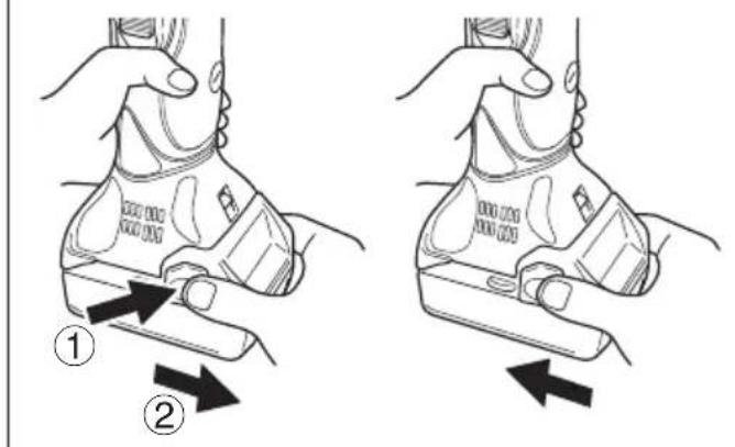
| Removing and inserting the battery | 1 188 | |
| Charging 2 188 | ||
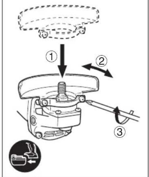
| Fitting and adjusting the wheel guard | 3 188 | |
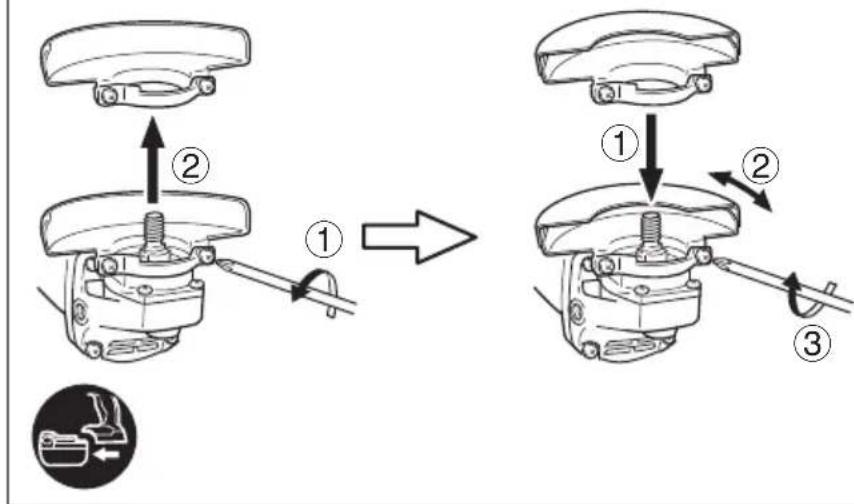
| Fitting and adjusting the wheel guard (for cutting) | 4 188 | |
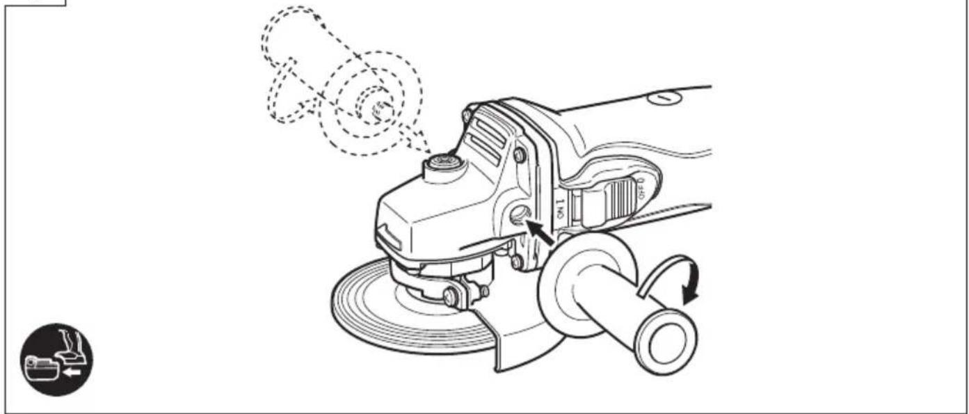
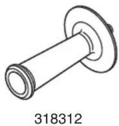
| Fixing the side handle 5 188 | ||
| Assembling depressed center wheel | 6 189 | |
| Assembling cutting wheel 7 189 | ||
| Switch operation 8 189 | ||
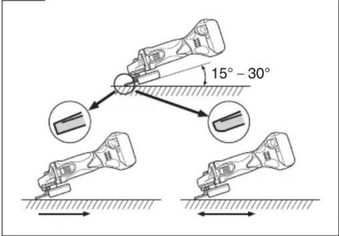
| Grinding angle and grinding method | 9 189 | |
| Remaining battery indicator 10 189 | ||
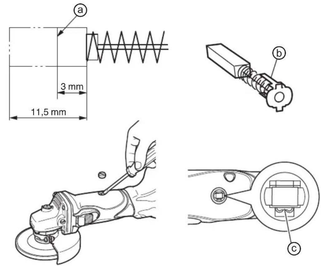
| Check and replacing the carbon brush | 11 190 | |
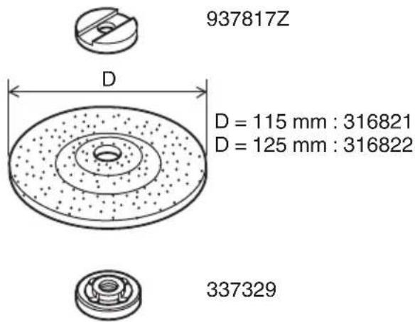
| Selecting accessories — 191 |
MAINTENANCE AND INSPECTION
1. Inspecting the depressed center wheel
Ensure that the depressed center wheel is free of cracks and surface defects.
2. Inspecting the mounting screws
Regularly inspect all mounting screws and ensure that they are properly tightened. Should any of the screws be loose, retighten them immediately. Failure to do so could result in serious hazard.
3. Maintenance of the motor
The motor unit winding is the very “heart” of the power tool. Exercise due care to ensure the winding does not become damaged and/or wet with oil or water.
4. Inspecting the carbon brushes (Fig. 11)
The motor employs carbon brushes which are consumable parts. Since and excessively worn carbon brush can result in motor trouble, replace the carbon brush with new ones when it becomes worn to or near the “wear limit” ⓐ. In addition, always keep carbon brushes clean and ensure that they slide freely within the brush holders.
NOTE
When replacing the carbon brush with a new one, be sure to use the HiKOKI Carbon Brush Code No. 999054.
5. Replacing carbon brushes (Fig. 11)
Take out the carbon brush by fi rst removing the brush cap and then hooking the protrusion of the carbon brush with a fl at head screw driver, etc.
When installing the carbon brush, choose the direction so that the nail ⓑ of the carbon brush agrees with the contact portion Ⓐ outside the brush tube. Then push it in with a finger. Lastly, install the brush cap.
CAUTION
Be absolutely sure to insert the nail of the carbon brush into the contact portion outside the brush tube. (You can insert whichever one of the two nails provided).
Caution must be exercised since any error in this operation can result in the deformed nail of the carbon brush and may cause motor trouble at an early stage.
6. Cleaning on the outside
When the cordless disc grinder is stained, wipe with a soft dry cloth or a cloth moistened with soapy water. Do not use chloric solvents, gasoline or paint thinner, for they melt plastics.
7. Storage
Store the cordless disc grinder in a place in which the temperature is less than 40^ C, and out of reach of children.
NOTE
Make sure that the battery is fully charged when stored for a long period (3 months or more). The battery with smaller capacity may not be able to be charged when used, if stored for a long period.
NOTE
Storing lithium-ion batteries.
Make sure the lithium-ion batteries have been fully charged before storing them.
Prolonged storage of batteries with a low charge may result in performance deterioration, significantly reducing battery usage time or rendering the batteries incapable of holding a charge.
However, signifi cantly reduced battery usage time ma be recovered by repeatedly charging and using the batteries two to fi ve times.
If the battery usage time is extremely short despite repeated charging and use, consider the batteries dead and purchase new batteries.
CAUTION
In the operation and maintenance of power tools, the safety regulations and standards prescribed in each country must be observed.
Important notice on the batteries for the HiKOKI cordless power tools
Please always use one of our designated genuine batteries. We cannot guarantee the safety and performance of our cordless power tool when used with batteries other than these designated by us, or when the battery is disassembled and modified (such as disassembly and replacement of cells or other internal parts).
GUARANTEE
We guarantee HiKOKI Power Tools in accordance with statutory/country specific regulation. This guarantee does not cover defects or damage due to misuse, abuse, or normal wear and tear. In case of complaint, please send the Power Tool, undismantled, with the GUARANTEE CERTIFICATE found at the end of this Handling instruction, to a HiKOKI Authorized Service Center.
Information concerning airborne noise and vibration
The measured values were determined according to EN60745 and declared in accordance with ISO 4871.
Measured A-weighted sound power level: 92 dB (A). Measured A-weighted sound pressure level: 81 dB (A). Uncertainty K : 3 dB (A).
Wear hearing protection.
Vibration total values (triax vector sum) determined according to EN60745.
Surface grinding:
Vibration emission value a_h , AG = 5.0 m/s ^2
Uncertainty K = 1.5 m/s ^4
The declared vibration total value has been measured in accordance with a standard test method and may be used for comparing one tool with another. It may also be used in a preliminary assessment of exposure.
WARNING
☐ The vibration emission during actual use of the power tool can differ from the declared total value depending in the ways in which the tool is used.
- Identify safety measures to protect the operator that are based on an estimation of exposure in the actual conditions of use (taking account of all parts of the operating cycle such as the times when the tool is switched off and when it is running idle in addition to the trigger time).
NOTE
Due to HiKOKI's continuing program of research and development, the specifications herein are subject to change without prior notice.
VEILIGHEIDSWAARSCHUWINGEN
VOOR SLIJPEN EN DOORSLIJPEN
● Pilot lysindikation
VEDLIKEHOLD OG INSPEKSJON
G14DSL / G18DSL / G18DSL(S):
Akkus sarokcsiszoló
G14DSL / G18DSL / G18DSL(S):
DODATNA VARNOSTNA OPOZORILA
 |  |  | 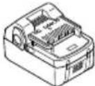 | 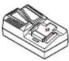 | 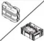 | 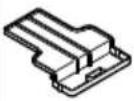 | |
| G14DSLG18DSLG18DSL(S) | 1 | 1 | 1 | 2 | 1 | 1 | 1 |
| G14DSL(NN)G18DSL (NN)G18DSL(S) (NN) | 1 | 1 | 1 | - | - | - | - |
1
2
3
4
5
natural_image
Line drawing of a power tool with motion arrows indicating rotation and adjustment (no text or symbols)6
7
flowchart
graph TD
    A["①"] --> B["②"]
    B --> C["③"]
    C --> D["⑤"]
    D --> E["⑥"]
    E --> F["④"]
    style A fill:#f9f,stroke:#333
    style B fill:#ccf,stroke:#333
    style C fill:#cfc,stroke:#333
    style D fill:#fcc,stroke:#333
    style E fill:#cff,stroke:#333
    style F fill:#ffc,stroke:#333
8
9
10

11
natural_image
Technical line drawing of a mechanical component with flanged ends and a cylindrical shaft (no text or symbols)
natural_image
Technical line drawing of a mechanical tool (no text or symbols on the object itself)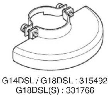
natural_image
Technical drawing of a mechanical component with no visible text or symbols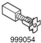
natural_image
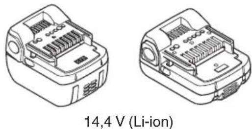
Technical line drawings of two battery modules with internal compartments, labeled '14,4 V (Li-ion)' below (no other text or symbols)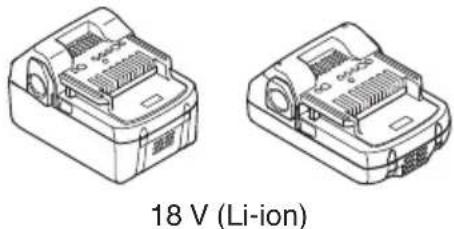
natural_image
Two technical line drawings of a battery housing with ventilation slots and a 18V lithium-ion component label (no other text or symbols)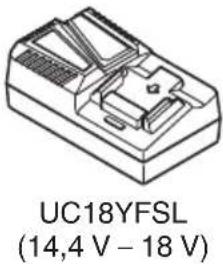
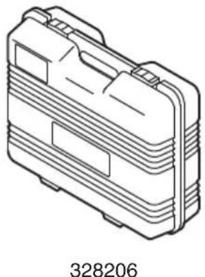
natural_image
Line drawing of a mechanical device casing with no visible text or symbols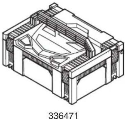
natural_image
Isometric technical drawing of a mechanical housing or enclosure with internal components (no text or symbols)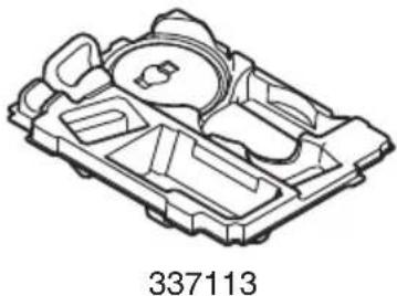
natural_image
Technical line drawing of a mechanical component with no visible text or symbols
natural_image
Line drawing of a quill pen with inkwell, no text or symbols present| English Dansk Română | ||||
| GUARANTEE CERTIFICATE1 Model No.2 Serial No.3 Date of Purchase4 Customer Name and Address5 Dealer Name and Address(Please stamp dealer name and address) | GARANTIBEVIS1 Modelnummer2 Serienummer3 Købsdato4 Kundes navn og adresse5 Forhandlers navn og adresse(Indsæt stempel med forhandlers navn og adresse) | CERTIFICAT DE GARANTIE1 Model nr.2 Nr. de serie3 Data cumpărării4 Numele și adresa clientului5 Numele și adresa distribuitorului(Vă rugăm aplicați ștampila cu numele și adresa distribuitorului) | ||
| Deutsch Norsk Slovenščina | ||||
| GARANTIESCHEIN1 Modell-Nr.2 Serien-Nr.3 Kaufdatum4 Name und Anschrift des Kunden5 Name und Anschrift des Händlers(Bitte mit Namen und Anschrift des Handlers abstempeln) | GARANTISERTIFIKAT1 Modellnr.2 Serienr.3 Kjøpsdato4 Kundens navn og adresse5 Forhandlerens navn og adresse(Vennligst stemple forhandlerens navn og adresse) | GARANCIJSKO POTRDILO1 Št. modela2 Serijska št.3 Datum nakupa4 Ime in naslov kupca5 Ime in naslov prodajalca(Prosimo vtsnite žig z imenom in naslovom prodajalca) | ||
| Français Suomi Slovenčina | ||||
| CERTIFICAT DE GARANTIE1 No. de modèle2 No de série3 Date d'achat4 Nom et adresse du client5 Nom et adresse du revendeur(Cachet portant le nom et l'adresse du revendeur) | TAKUUTODISTUS1 Malli nro2 Sarja nro3 Ostopăivămâără4 Asiakkaan nimi ja osoite5 Myyjăn nimi ja osoite(Leimaa myyjăn nimi ja osoite) | ZÁRUČNÝ LISTA1 Č. modelu2 Sériové č.3 Dátum zakúpenia4 Meno a adresa zákaznika5 Názov a adresa predajcu(Pečiatka s názvom a adresou predajcu) | ||
| Italiano Ελληνικά Български | ||||
| CERTIFICATO DI GARANZIA1 Modello2 N° di serie3 Data di acquisto4 Nome e indirizzo dell'acquirente5 Nome e indirizzo del rivenditore(Si prega di apporre il timbro con questi dati) | ПІЗТОПОІНТІКО ЕГГУНЄНЕ1 Ap. Movtėlou2 Aŭξων Ap.3 Нμερομηνία αγοράς4 Ovojama kai διεύθυνση πελάτη5 Ovojama kai διεύθυνση μεταπωλητή(Παρακαλούμε να χρησιμοποιηθεί σφραγίδα) | ГАРАНЦИОНЕН СЕРТИФИКАТ1 Модел No2 Сериен No3 Дата за закупуване4 Име и адрес на клиента5 Име и адрес на търговеца(Моля, отпечатайте името и адрес на дильра) | ||
| Nederlands Polski Srpski | ||||
| GARANTIEBEWIJS1 Modelnummer2 Serienummer3 Datum van aankoop4 Naam en adres van de gebruiker5 Naam en adres van de handelaar(Stempel a.u.b. naam en adres vande de handelaar) | GWARANCJA1 Model2 Numer seryjny3 Data zakupu4 Nazwa klienta i adres5 Nazwa dealera i adres(Pieczęć punktu sprzedaży) | GARANTNI SERTIFIKAT1 Br. modela.2 Serijski br.3 Datum kupovine4 Ime i adresa kupca5 Ime i adresa prodavca(Molimo da stavite pečat na ime i adresu trgovca) | ||
| Español Magyar Hrvatski | ||||
| CERTIFICADO DE GARANTÍA1 Número de modelo2 Número de serie3 Fecha de adquisición4 Nombre y dirección del cliente5 Nombre y dirección del distributor(Se ruega poner el sello del distribuidor con su nombre y dirección) | GARANCIA BIZONYLAT1 Tipusszám2 Sorozatszám3 A vásárlás dátuma4 A Vásárló neve és címe5 A Kereskedő neve és címe(Kárjük ide olhelyezni a Kereskedő nevének és címének pecsétjét) | JAMSTVENI CERTIFIKAT1 Br modela.2 Serijski br.3 Datum kupnje4 Ime i adresa kupca5 Ime i adresa trgovca(Molimo stavite pečat na ime i adresu trgovca) | ||
| Português Čeština Український | ||||
| CERTIFICADO DE GARANTIA1 Número do modelo2 Número do série3 Data de compra4 Nome e morada do cliente5 Nome e morada do distribuidor(Por favor, carimbe o nome e morada do distribuidor) | ZÁRUČNÍ LIST1 Model č.2 Série č.3 Datum nákupu4 Jméno a adresa zákazníka5 Jméno a adresa prodejce(Prosíme o razitko se jménem a adresou prodejce) | ГАРАНТИЙНИЙ СЕРТИФИКАТ1 No моделі2 No серії3 Дата придбання4 Im'я і адреса клієнта5 Im'я і адреса дилера(Будь ласка, поставте печатку з іменем і адресою дилера) | ||
| Svenska Türkçe | Русский | |||
| GARANTICERTIFIKAT1 Modellnr2 Serienr3 Inköpsdatum4 Kundens namn och adress5 Försäljarens namn och adress(Stämpla försäljarens namn och adress) | GARANTI SERTÍFİKASI1 Model No.2 Seri No.3 Satin Alma Tarihi4 Müşteri Adı ve Adresi5 Bayi Adı ve Adresi(Lütfen bayi adini ve adresini kaşe olarak basin) | ГАРАНТИЙНЫЙ СЕРТИФИКАТ1 Модель No2 Серийный No3 Дата покупки4 Название и адрес заказчика5 Название и адрес дилера(Пожалуйста, внесите название и адрес дилера) | ||
HiKOKI
| 1 | |
| 2 | |
| 3 | |
| 4 | |
| 5 |
Siemensring 34, 47877 willich, Germany
Tel: +49 2154 49930
Fax: +49 2154 499350
URL: http://www.hikoki-powertools.de
Hikoki Power Tools Netherlands B.V.
Brabanthaven 11, 3433 PJ Nieuwegein, The Netherlands
Tel: +31 30 6084040
Fax: +31 30 6067266
URL: http://www.hikoki-powertools.nl
Hikoki Power Tools (U.K.) Ltd.
Precedent Drive, Rooksley, Milton Keynes, MK 13, 8PJ,
United Kingdom
Tel: +44 1908 660663
Fax: +44 1908 606642
URL: http://www.hikoki-powertools.uk
Hikoki Power Tools France S.A.S.
Hikoki Power Tools Belgium N.V./S.A.
Koningin Astridlaan 51, B-1780 Wemmel, Belgium
Tel: +32 2 460 1720
Fax: +32 2 460 2542
URL http://www.hikoki-powertools.be
Hikoki Power Tools Italia S.p.A
Via Piave 35, 36077, Altavilla Vicentina (VI), Italy
Tel: +39 0444 548111
Fax: +39 0444 548110
URL: http://www.hikoki-powertools.it
Hikoki Power Tools Ibérica, S.A.
C/ Puigbarral, 26-28, Pol. Ind. Can Petit, 08227 Terrassa
(Barcelona), Spain
Tel: +34 93 735 6722
Fax: +34 93 735 7442
URL: http://www.hikoki-powertools.es
Kjeller Vest 7, N-2007 Kjeller, Norway
Tel: (+47) 6692 6600
Fax: (+47) 6692 6650
URL: http://www.hikoki-powertools.no
Hikoki Power Tools Sweden AB
Rotebergsvagen 2B SE-192 78 Sollentuna, Sweden
Tel: (+46) 8 598 999 00
Fax: (+46) 8 598 999 40
URL: http://www.hikoki-powertools.se
Hikoki Power Tools Denmark A/S
Lillebaeltsvej 90, 6715 Esbjerg N, Denmark
Tel: (+45) 75 14 32 00
Fax: (+45) 75 14 36 66
URL: http://www.hikoki-powertools.dk
Hikoki Power Tools Finland Oy
Tupalankatu 9, 15680 Lahti, Finland
Tel: (+358) 20 7431 530
Fax: (+358) 20 7431 531
URL: http://www.hikoki-powertools.fi
Hikoki Power Tools Hungary Kft.
Hikoki Power Tools Romania S.R.L.
Ring Road, No. 66, Mustang Traco Warehouses, Warehouse
No.1, Pantelimon City, 077145, Ilfov County, Romania
natural_image
Line drawing of a quill pen in an inkwell (no text or symbols)
natural_image
Line drawing of a quill pen in an inkwell (no text or symbols)| English Nederlands | ||
| EC DECLARATION OF CONFORMITYWe declare under our sole responsibility that Cordless Disc Grinder, identified by type and specific identification code *1), is in conformity with all relevant requirements of the directives *2) and standards *3). Technical fi le at *4) – See below.The European Standard Manager at the representative office in Europe is authorized to compile the technical fi le. The declaration is applicable to the product affi xed CE marking. | EC VERKLARING VAN CONFORMITEITWij verklaren onder onze eigen verantwoordelijkheid dat Snoerloze haakse slijpmachine, geïdentificeerd door het type en de specifieke identificatiecode*1), voldoet aan alle relevante bepalingen van de richtlijnen*2) en normen*3). Technische documentatie bij*4) – zie onder.De Europese Normen Manager bij de vertegenwoordiging in Europa is gemachtigd om het technisch dossier samen te stellen.Deze verklaring is van toepassing op producten voorzien van de CE-markeringen. | |
| Deutsch Español | ||
| EG-KONFORMITÄTSERKLÄRUNGWir erklären in alleiniger Verantwortung, dass der durch den Typ und den spezifischen Identifizierungscode *1) identifizierte Akku-Winkelschleifer allen einschlägigen Bestimmungen der Richtlinien *2) und Normen *3) entspricht. Technische Unterlagen unter *4) – Siehe unten.Die Leitung der repräsentativen Behörde für europäische Normen und Richtlinien ist berechtigt, die technischen Unterlagen zusammenzustellen.Die Erklärung gilt für die an dem Produkt angebrachte CE-Kennzeichnung. | DECLARACIÓN DE CONFORMIDAD DE LA CEDeclaramos bajo nuestra única responsabilidad que la Amoladora angular a bateria, identificada por tipo y por código de identificación específico *1), está en conformidad con todas las disposiciones correspondientes de las directivas *2) y de las normas *3). Documentación técnica en *4) – Ver a continuación.El Director de Normas Europeas en la oficina de representación en Europa está autorizado para elaborar el expediente técnico.La declaración se aplica al producto con marcas de la CE. | |
| Français Português | ||
| DECLARATION DE CONFORMITE CENous déclarons sous notre entière responsabilité que la meuleuse à batterie, identifiée par le type et le code d'identification spécifique *1) est en conformité avec toutes les exigences applicables des directives *2) et des normes *3). Dossier technique en *4) - Voir ci-dessous.Le Gestionnaire des normes européennes du bureau de représentation en Europe est autorisé à constituer le dossier technique.Cette déclaration s'applique aux produits désignés CE. | DECLARAÇÃO DE CONFORMIDADE CEDeclaramos, sob nossa única e inteira responsabilidade, que Rebarbadora a Bateria, identificada por tipo e código de identificação específico *1), está em conformidade com todos os requerimentos relevantes das diretivas *2) e normas *3). Ficheiro técnico em *4)– Consulte abaixo.O Gestor de Normas Europeias no escritório de representação na Europa está autorizado a compilar o fi cheiro técnico.A declaração aplica-se aos produtos com marca CE. | |
| Italiano Svenska | ||
| DICHIARAZIONE DI CONFORMITÀ CEDichiariamo sotto la nostra esclusiva responsabilità che la smerigliatrice angolare a batteria, identificata dal tipo e dal codice identificativo specifico *1), è conforme a tutti i requisiti delle direttive *2) e degli standard *3). Documentazione tecnica presso *4) – Vedere sotto.Il gestore delle norme europee presso l'ufficio di rappresentanza in Europa è autorizzato a compilare il fascicolo tecnico.La dichiarazione è applicabile ai prodotti cui sono applicati i marchi CE. | EG-DEKLARATION BETRÄFFANDE LIKFORMIGHETViförklarar på eget ansvar att denna batteridrivna vinkelslip, identifierad enligt typ och särskild identifikationskod *1), överensstämmer med alla relevanta krav i direktiven *2) och standarderna *3). Teknisk fil enligt *4) – Se nedan.Den europeiska standardansvariga på representationskontoret i Europa är auktoriserad att sammanställa den tekniska fi len.Denna försåkran gäller för produkten med tillhörande CE-märkning. | |
| *1) G18DSL C337068R C337067SG14DSL C337424SKC18DLL C337068R*2) 2006/42/EC, 2014/30/EU, 2014/35/EU, 2011/65/EU*3) EN60745-1:2009+A11:2010EN60745-2-3:2011+A2:2013+A11:2014+A12:2014+A13:2015EN60335-1:2012+A11:2014EN60335-2-29:2004+A2:2010EN55014-1:2006+A1:2009+A2:2011EN55014-2:1997+A1:2001+A2:2008 | ||
*4) Representative offi ce in EuropeHikoki Power Tools Deutschland GmbHSiemensring 34, 47877 Willich, GermanyHead offi ce in Japan  Koki Holdings Co., Ltd.Shinagawa Intercity Tower A, 15-1, Konan 2-chome, Minato-ku, Tokyo, Japan Koki Holdings Co., Ltd.Shinagawa Intercity Tower A, 15-1, Konan 2-chome, Minato-ku, Tokyo, Japan | 29. 6. 2018Naoto YamashiroEuropean Standard Manager29. 6. 2018 A. NakagawaCorporate Offi cer A. NakagawaCorporate Offi cer | |
| Dansk Polski | ||
| EF-OVERENSSTEMMELSESERKLÆRINGVi erklærer os fuldstændig ansvarlige for, at den Batteridrevede vinkelboremsakine, identificeret ved type og specifik identifikationskode *1), er i overensstemmelse med alle relevante krav i direktiverne *2) og standarderne *3). Teknisk fil i *4) – Se nedenfor. Lederen af europæiske standarder på repræsentationskontoret i Europa er bemyndiget til at kompilere den tekniske fi I. Erklæringen gælder produktet, der er mærket med CE. | DEKLARACJA ZGODNOŚCI Z WEOświadczamy na własną wyłączną odpowiedzialność, że Akumulatorowa szlifierka kątowa podanego typu i oznaczona unikalnym kodem identyfikacyjnym. *1) jest zgodna z wszystkimi właściwymi wymogami dyrektyw *2) i norm *3). Dokumentacja techniczna w *4) – Patrz poniżej.Menedżer Norm Europejskich przedstawicielstwa firmy w Europie jest upoważniony do sporządzania dokumentacji technicznej.Niniejsza deklaracja ma zastosowanie do produktu opatzonego znakiem CE. | |
| Norsk Magyar | ||
| EF'S ERKLÆRING OM OVERENSSTEMMELSEVi erklærer på eget ansvar at oppladbar batteridrevet vinkelborskrutrekker, identifisert etter type og spesifikk identifikasjonskode *1), er i samsvar med alle relevante krav i direktiver *2) og standarder *3). Teknisk fil under *4) - Se nedenfor. Styreren for europeiske standarder ved representantkontoret i Europa er autorisert til å kompilere den tekniske fi len. Erklæringen gjelder for CE-merket på produktet. | EK MEGFELELŐSÉGI NYILATKOZATA kizárólagos felelősségünkre kijelentjük, hogy az Akkus sarokcsiszolo, mely tipus és egyedi azonositó kód *1) alapján azonositott, megfelel az irányelvek vonatkozó követelményeinek *2) és szabványainak *3). Műszaki fájl a *4) - Lásd alább.Az EU képviseleti iroda európai szabványügyi menedzsere jogosult a műszaki dokumentáció összeállítására.Jelen nyilatkozat a terméken feltüntetett CE jelzésre vonatkozik. | |
| Suomi Češtiņa | ||
| EY-ILMOITUS YHDENMUKAISUUDESTAVakuutamme yksinomaisella vastuullamme, että akkutoiminen kulmahiomakone, joka identifi oidaan tyypin ja erityis tunnistuskoodin *1) perusteella, on kaikkien direktiivien *2) ja standardien *3) asiaankuuluvien vaatimusten mukainen. Tekninen tiedosto kohdassa *4) – katso alta.Eurooppalaisten standardien hallintaelin Euroopan edustustossa on valtuutettu kokoamaan teknisen tiedoston.Ilmoitus on sovellettavissa tuotteeseen kiinnitettyyn CE-merkintään. | PROHLÁŠENÍ O SHODĚ S ESProhlašujeme na svou výhradní zodpovědnost, že akku úhlová bruska, identifikovaná podle typu a specifického identifikačniho kódu *1), je v souladu se všemi příslušnými požadavky směrnic *2) a norem *3). Technický soubor *4) - viz niže.K sestavení technické dokumentace je oprávněn manažer pro evropské standardy ve evropském obchodním zastoupení.Toto prohlášení platí pro výrobek označený značkou CE. | |
| Ελληνικά Türkçe | ||
| ΕΚ ΔΗΛΩΣΗ ΕΝΑΡΜΟΝΙΣΜΟΥΔηλώνουμε με αποκλειστική μας ευθύνη ότι ο Γωνιακός τροχός λειάνσεως μπαταρίας, ο οποίος προσδιορίζεται από τον τύπο και ειδικό αναγνωριστικό κωδικό *1), είναι συμφωνος με όλες τις σχετικές απαιτήσεις των Οδηγιών *2) και στα σχετικά πρότυπα *3). Τεχνικό Αρχείο στο *4) – Δείτε παρακάτω.Ο Διαχειριστής Ευρωπαϊκών Προτύπων στο γραφείο εκτροσώπησης στην Ευρώτη είναι εξουσιοδοτημένος για τη σύνταξη του τεχνικού φακέλου.Η δήλωση ισχύει μόνο για το προϊόν που είναι τοποθετημένη σήμανση CE. | AT UYGUNLUK BEYANITip ve özel tanım koduyla *1) tanımlı Akülü Taşlama’nin direktiflerin *2) ve standartlarin *3) tüm ilgili gereksinimlerine uygun olduğunu tamamen kendi sorumluluğumuz altında beyan ederiz. Teknik dosya *4)'dedir – Aşağıya bakin.Avrupa'daki temsilcilik ofisindeki Avrupa Standartları Yöneticisi, teknik dosyayi derlemek için yetkilendirilmiştir.Beyan, üzerinde CE işareti bulunan ürünler için geçerlidir. | |
| *1) G18DSL C337068R C337067SG14DSL C337424SKC18DLL C337068R*2) 2006/42/EC, 2014/30/EU, 2014/35/EU, 2011/65/EU*3) EN60745-1:2009+A11:2010EN60745-2-3:2011+A2:2013+A11:2014+A12:2014+A13:2015EN60335-1:2012+A11:2014EN60335-2-29:2004+A2:2010EN55014-1:2006+A1:2009+A2:2011EN55014-2:1997+A1:2001+A2:2008 | ||
*4) Representative office in EuropeHikoki Power Tools Deutschland GmbHSiemensring 34, 47877 Willich, GermanyHead office in JapanKoki Holdings Co., Ltd.Shinagawa Intercity Tower A, 15-1, Konan 2-chome, Minato-ku, Tokyo, Japan | 29. 6. 2018Naoto YamashiroEuropean Standard Manager29. 6. 2018[87WZA. NakagawaCorporate Officer | |
| Română Srpski | ||
| DECLARATIE DE CONFORMITATE CEDeclarăm pe propria răspundere că Polizorul unghiular cu accumulator, identificat după tipul și codul de identificare specific *1), este în conformitate cu toate cerințele relevante ale directivelor *2) și ale standardelor *3). Fisier tehnic la *4) – Vezi mai jos.Managerul standardelor europene de la biroul reprezentanței din Europa este autorizat să întocmească dosarul tehnic.Declarația se referă la produsul pe care este aplicat semnul CE. | EZ DEKLARACIJA O USAGLAŠENOSTIPod punom odgovornošću izjavljujemo da je Bežična ugaona bušilica, identifikovana prema tipu i specičnom identifikacionom kodu *1), u skladu sa svim relevantnim zahtevima direktiva *2) i standardima *3). Tehnička datoteka pod *4) - Pogledajte dole.Direktor za evropske standarde u kancelariji predstavništva u Evropi je odgovoran za sastavljanje tehničke dokumentacije.Deklaracija je primenjiva na proizvod na koji je stavljena CE oznaka. | |
| Slovenščina Hrvatski | ||
| ES IZJAVA O SKLADNOSTINa lastno odgovornost izjavljamo, da je Akumulatorski kolutni brusilnik, označen z vrsto in posebno identifikacijsko kodo *1), v skladu z vsemi ustreznimi zahtevami direktiv *2) in standardov *3). Tehnička dokumentacija pod *4) – glejte spodaj.Upravitelj evropskih standardov na predstavništvu v Evropi je pooblaščen za pripravo tehnične dokumentacije.Deklaracija je označena na izdelku s pritrjeno oznako CE. | EZ IZJAVA O SUKLADNOSTI Izjavljujemo pod vlastitom odgovornošću da je bežična kutna brusilica, identificirana prema vrsti i posebnom identifikacijskom kodu *1), u skladu sa svim relevantnim zahtjevima direktiva *2) i standarda *3). Tehnička dokumentacija na *4) - Vidi dolje.Menadžer za europske standarde u europskom predstavništvu tvrtke ovlašten je za sastavljanje tehničke dokumentacije.Izjava se primjenjuje na proizvod na kojem je stavljena CE oznaka. | |
| Slovenčina Український | ||
| ES VYHLÁSENIE O ZHODETýmto vyhlasujeme na vlastnú zodpovednosť, že výrobok Aku uhlová brúška identifikovaný podľa typu a špecifického identifikačného kódu *1) je v zhode so všetkými prislušnými požiadavkami smernic *2) a noriem *3). Technický súbor v *4) – Pozrite nižšie.Manažér európsych noriem na zastupujúcom úrade v Európe má oprávnenie na zostavovanie technickej dokumentácie.Toto vyhlásenie sa vzťahuje na výrobok označený značkou CE. | ДЕНЛАРАЦІЯ ВІДПОВІДНОСТИ ЄССМи заявляемо під нашу виключну відповідальність, що Акумуляторна кутова шліфувальна машина, визначена за типом та унікальним ідентифікаційним кодом *1), відповідае всім відповідним вимогам директив *2) та стандартів *3). Технічна документація на *4) - Див. нижче.Відповідальний за дотримання европейських стандартів у представництві в Європі уповноважений заповнювати технічний паспорт.Ця декларація дійсна щодо виробу, маркованого CE. | |
| Български Русский | ||
| ЕО ДЕНЛАРАЦИЯ ЗА СЪОТВЕТСТВИЕДекларираме на своя собствена отговорност, че Безжичната ъглова бормашина, идентифицирана по тип и специален идентификационен код *1), е в съответствие с всички съответни изисквания на директивите *2) и стандартите *3). Техническо досие в *4) - Винте по-долу.Мениджърът по европейските стандарти в представителния офис в Европа е упълномощен да съставя техническото досие.Декларацията е приложима за продукта, който има поставена CE маркировка. | ДЕНЛАРАЦИЯ СООТВЕТСТВИЯ ЕСМы с полной ответственностью заявляем, что аккумуляторная угловая шлифовальная машина, идентифицируемая по типу и соответствующему идентификационному коду *1), отвечает всем соответствующим требованиям директив *2) и стандартов *3). Техническая документация в *4) – см. ниже.Менеджер по европейским стандартам в представительстве в Европе уполномочен составлять техническую документацию. Данная декларация относится к изделиям, на которых имеется маркировка CE. | |
| *1) G18DSL C337068R C337067SG14DSL C337424SKC18DLL C337068R*2) 2006/42/EC, 2014/30/EU, 2014/35/EU, 2011/65/EU*3) EN60745-1:2009+A11:2010EN60745-2-3:2011+A2:2013+A11:2014+A12:2014+A13:2015EN60335-1:2012+A11:2014EN60335-2-29:2004+A2:2010EN55014-1:2006+A1:2009+A2:2011EN55014-2:1997+A1:2001+A2:2008 | ||
| *4) Representative office in EuropeHikoki Power Tools Deutschland GmbHSiemensring 34, 47877 Willich, GermanyHead office in JapanKoki Holdings Co., Ltd.Shinagawa Intercity Tower A, 15-1, Konan 2-chome,Minato-ku, Tokyo, Japan | 29. 6. 2018Naoto YamashiroEuropean Standard Manager29. 6. 2018A. NakagawaCorporate Officer | |
- G 14DSL · G 18DSL · G 18DSL(S)
- (Original instructions)
- GENERAL POWER TOOL SAFETY WARNINGS
- WARNING
- 1) Work area safety
- 2) Electrical safety
- 3) Personal safety
- 4) Power tool use and care
- 5) Battery tool use and care
- PRECAUTION
- SAFETY WARNINGS COMMON FOR GRINDING OR ABRASIVE CUTTING-OFF OPERATIONS
- KICKBACK AND RELATED WARNINGS
- English
- SAFETY WARNINGS SPECIFIC FOR GRINDING AND ABRASIVE CUTTING-OFF OPERATIONS
- ADDITIONAL SAFETY WARNINGS SPECIFIC FOR ABRASIVE CUTTING- OFF OPERATIONS
- ADDITIONAL SAFETY WARNINGS
- CAUTION ON LITHIUM-ION BATTERY
- CAUTION
- SYMBOLS
- STANDARD ACCESSORIES
- APPLICATIONS
- SPECIFICATIONS
- NOTE
- CHARGING
- Disconnect the charger's power cord from the receptacle.
- Hold the charger firmly and pull out the battery.
- MAINTENANCE AND INSPECTION
- Inspecting the depressed center wheel
- Inspecting the mounting screws
- Maintenance of the motor
- Inspecting the carbon brushes (Fig. 11)
- Replacing carbon brushes (Fig. 11)
- Cleaning on the outside
- Storage
- Important notice on the batteries for the HiKOKI cordless power tools
- GUARANTEE
- Information concerning airborne noise and vibration
- VEILIGHEIDSWAARSCHUWINGEN
- VOOR SLIJPEN EN DOORSLIJPEN
- ● Pilot lysindikation
- VEDLIKEHOLD OG INSPEKSJON
- DODATNA VARNOSTNA OPOZORILA
- Hikoki Power Tools Netherlands B.V.
- Hikoki Power Tools (U.K.) Ltd.
- Hikoki Power Tools France S.A.S.
- Hikoki Power Tools Belgium N.V./S.A.
- Hikoki Power Tools Italia S.p.A
- Hikoki Power Tools Ibérica, S.A.
- Hikoki Power Tools Sweden AB
- Hikoki Power Tools Denmark A/S
- Hikoki Power Tools Finland Oy
- Hikoki Power Tools Hungary Kft.
- Hikoki Power Tools Romania S.R.L.
Brand : HiKOKI
Model : G 14DSL
Category : Grinder