
DV 20V2 - Drill HITACHI - Free user manual and instructions
Find the device manual for free DV 20V2 HITACHI in PDF.


| Product Type | Impact Drill |
| Model | DV20V2 |
| Brand | Hitachi |
| Input Power | 620 W |
| Voltage | 110-240 V (depending on region) |
| Reversible | Yes |
| Speed Settings | 2 (Low/High) |
| No Load Speed (Low) | 0 - 1100 min⁻¹ |
| No Load Speed (High) | 0 - 2600 min⁻¹ |
| Drilling Capacity (Steel) | 13 mm (Low), 8 mm (High) |
| Drilling Capacity (Concrete) | 20 mm (Low), 10 mm (High) |
| Drilling Capacity (Wood) | 35 mm (Low), 20 mm (High) |
| Full Load Impact Rate (Low) | 17600 min⁻¹ |
| Full Load Impact Rate (High) | 41600 min⁻¹ |
| Weight | 2.3 kg |
| Chuck Type | Keyed, 13 mm capacity |
| Standard Accessories | Chuck wrench, side handle, depth stopper |
| Optional Accessories | Carrying case, drill bits, driver bits |
| Sound Pressure Level | 102 dB(A) |
| Sound Power Level | 115 dB(A) |
| Vibration (Impact Drilling) | 14.0 m/s² |
| Safety Features | Reversing switch lock, double insulation, carbon brush wear indicator |
| Maintenance | Regular inspection of carbon brushes and mounting screws |
| Repairability | Replaceable carbon brushes, parts available via authorized service centers |
Frequently Asked Questions - DV 20V2 HITACHI
User questions about DV 20V2 HITACHI
0 question about this device. Answer the ones you know or ask your own.
Ask a new question about this device
Download the instructions for your Drill in PDF format for free! Find your manual DV 20V2 - HITACHI and take your electronic device back in hand. On this page are published all the documents necessary for the use of your device. DV 20V2 by HITACHI.
USER MANUAL DV 20V2 HITACHI
natural_image
Line drawing of a DV20V2 electric drill with handle and screwdriver (no text or symbols on the device itself)Read through carefully and understand these instructions before use.

Bruksanvisning
Brugsanvisning
Bruksanvisning
Käyttöohjeet
Handling Instructions
The exploded assembly drawing should be used only for authorized service center.
DV20V2
| Item No. | Part Name |
| 44 | Internal Wire (A) |
| 45 | Internal Wire (C) |
| 46 | Internal Wire (C) |
| 47 | Tube (D) |
| 48 | Support (B) |
| 49 | Noise Suppressor |
| 50 | Tapping Screw D4 · 16 |
| 51 | Cord Clip |
| 52 | Cord Armor |
| 53 | Tube (D) |
| 54 | Cord |
| 56A | Reversing Switch |
| 57B | Flat Hd. Screw (A) (Left Hand) M6 · 25 |
| 59 | CR Unit |
| 60 | Oil Seal |
| 61A | Dust Seal |
| 501 | Side Handle |
| 502 | Depth Stopper |
Parts are subject to possible modification without notice due to improvements. The drawing and the list are parts structural drawing and parts list of model DV20V2. For other models refer to the drawing and the list.
| Item No. | Part Name |
| 1 | Chuck Wrench 10G |
| 2 | Drill Chuck 13VLR |
| 3A | Retaining Ring For D32 Hole |
| 4A | Spindle |
| 5 | Steel Ball D4.76 |
| 6 | Ball Bearing (6002DDUCMPS2S) |
| 7A | Ratchet (A) |
| 8 | Spring (B) |
| 10A | Gear Cover Ass'y |
| 11 | Spring |
| 12 | Low Speed Gear |
| 13 | Clutch Disc |
| 14 | High Speed Gear |
| 15 | Washer |
| 16 | Outer Cover |
| 17 | Inner Cover |
| 18 | Changing Plate |
| 19 | Ball Bearing (608VVMC2EPS2L) |
| 20 | Push Button |
| 21 | Bearing Holder |
| 22 | Seal Lock Screw (W/Sp. Washer) M5 · 12 |
| 23A | Shift Lever Ass'y |
| 24 | O-Ring |
| 25A | Shift Spring |
| 26 | Second Pinion |
| 27 | Armature |
| 28 | Fan Guide |
| 29 | Rubber Bushing |
| 30 | Stator |
| 31 | Housing |
| 32A | Tapping Screw (W/Flange) D5 · 60 |
| 33 | Name Plate |
| 34 | Bearing Seal |
| 35A | Handle (A) ·(B) Set |
| 36A | Tapping Screw (W/Frange) D4 · 16 |
| 37 | HITACHI Label |
| 38 | Carbon Brush |
| 39 | Brush Holder |
| 41 | Speed Control Switch |
| 42A | Earth Terminal |
| 43 | Internal Wire (A) |

1



2


natural_image
Two mechanical diagrams showing a presser pressing a bolt, with no text or symbols present.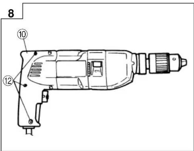
| Svenska Dansk Norsk | |||
| 1 | Spak för ändring av rotationsriktning | Omskifterknap Spak | |
| 2 | Momentomvandlare Skifteplade Skifteplate | ||
| 3 | BORNING ROTATION ROTERING | ||
| 4 | SLAG + BORNING (rotation med slag) | ROTATION + SLAG ROTERING + | SLAG |
| 5 | Hastighetsväljare Hastiglædsomskifter Giromkopler med skala | ||
| 6 | Avnötningsgråns Slidgrænse Slitasjegrense | ||
| 7 | No på kolborste Kul No Kullbørstens No | ||
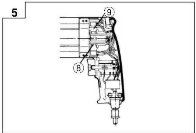
| 8 | Kolborste Kul Kullbørste | ||
| 9 | Kolborsthållare Kulholder Børsteholder | ||
| 10 | Handtaget (A) | Håndtag (A) | Håndtak (A) |
| 11 | Handtaget (B) | Håndtag (B) | Håndtak (B) |
| 12 | Själgängande skruvar D4 · 16 | D4 · 16 Bygningsskruer | D4 · 16 Bygningsskruer |
| Suomi | English | ||
| 1Vipu | Lever | ||
| 2Vaihtolevy | Change plate | ||
| 3PORAUS | ROTATION | ||
| 4PORAUS + ISKU | ROTATION + IMPACT | ||
| 5Nopeudenvaihtokytkinlevy | Gear shift dial | ||
| 6Kulutusraja Wear limit | |||
| 7Hiiliharjojen No. | No. of carbon brush | ||
| 8Hiiliharja | Carbon brush | ||
| 9Hiiliharjan pidike | Brush holder | ||
| 10Kådensijan (A) | Handle (A) | ||
| 11Kådensijan (B) | Handle (B) | ||
| 12 | D4 · 16 Kierteitysruuvit | D4 · 16 Tapping screws | |
SÄKERHETSFÖRESKRIFTER FÖR ELVERKTYG
WARNING!
13,0 m/s ^2 (DV14V)
GENERELLE FORSIGTIGHEDSREGLER
ADVARSEL!
VEDLIKEHOLD OG INSPEKSJON
WARNING! When using electric tools, basic safety precautions should always be followed to reduce the risk of fire, electric shock and personal injury, including the following.
Read all these instructions before operating this product and save these instructions.
For safe operations:
- Keep work area clean. Cluttered areas and benches invite injuries.
- Consider work area environment. Do not expose power tools to rain. Do not use power tools in damp or wet locations. Keep work area well lit. Do not use power tools where there is risk to cause fire or explosion.
- Guard against electric shock. Avoid body contact with earthed or grounded surfaces. (e.g. pipes, radiators, ranges, refrigerators).
- Keep children away. Do not let visitors touch the tool or extension cord. All visitors should be kept away from work area.
- Store idle tools. When not in use, tools should be stored in a dry, high or locked up place, out of reach of children.
- Do not force the tool. It will do the job better and safer at the rate for which it was intended.
- Use the right tool. Do not force small tools or attachments to do the job of a heavy duty tool. Do not use tools for purposes not intended; for example, do not use circular saw to cut tree limbs or logs.
- Dress properly. Do not wear loose clothing or jewellery, they can be caught in moving parts. Rubber gloves and non-skid footwear are recommended when working outdoors. Wear protecting hair covering to contain long hair.
- Use eye protection. Also use face or dust mask if the cutting operation is dusty.
- Connect dust extraction equipment. If devices are provided for the connection of dust extraction and collection facilities ensure these are connected and properly used.
- Do not abuse the cord. Never carry the tool by the cord or yank it to disconnect it from the receptacle. Keep the cord away from heat, oil and sharp edges.
- Secure work. Use clamps or a vise to hold the work. It is safer than using your hand and it frees both hands to operate tool.
- Do not overreach. Keep proper footing and balance at all times.
- Maintain tools with care. Keep cutting tools sharp and clean for better and safer performance. Follow instructions for lubrication and changing accessories. Inspect tool cords periodically and if damaged, have it repaired by authorized service center. Inspect extension cords periodically and replace, if damaged. Keep handles dry, clean, and free from oil and grease.
- Disconnect tools. When not in use, before servicing, and when changing accessories such as blades, bits and cutters.
- Remove adjusting keys and wrenches. Form the habit of checking to see that keys and adjusting wrenches are removed from the tool before turning it on.
English
- Avoid unintentional starting. Do not carry a plugged-in tool with a finger on the switch. Ensure switch is off when plugging in.
- Use outdoor extension leads. When tool is used outdoors, use only extension cords intended for outdoor use.
- Stay alert. Watch what you are doing. Use common sense. Do not operate tool when you are tired.
-
Check damaged parts. Before further use of the tool, a guard or other part that is damaged should be carefully checked to determine that it will operate properly and perform its intended function. Check for alignment of moving parts, free running of moving parts, breakage of parts, mounting and any other conditions that may affect its operation. A guard or other part that is damaged should be properly repaired or replaced by an authorized service center unless otherwise indicated in this handling instructions. Have defective switches replaced by an authorized service center. Do not use the tool if the switch does not turn it on and off.
-
Warning
The use of any accessory or attachment, other than those recommended in this handling instructions, may present a risk of personal injury. - Have your tool repaired by a qualified person. This electric tool is in accordance with the relevant safety requirements. Repairs should only be carried out by qualified persons using original spare parts. Otherwise this may result in considerable danger to the user.
PRECAUTIONS ON USING IMPACT DRILL
- Before drilling into walls, ceilings or floors, ensure that there are no concealed power cables inside.
- For DV20V2 and DV14V
When boring concrete or similar hard materials in IMPACT mode, set the bit rotation switch lever to the R-side. (Fig. 6)
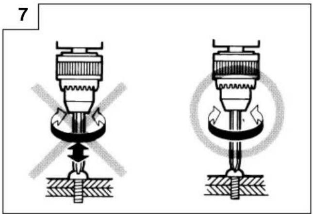
○ When tightening or loosening screws, be sure to set the change plate in ROTATION mode. (Fig. 7)
SPECIFICATIONS
| Model DV20V2 DV20V3 DV20T DV1 | 4V | |||||||
| Voltage (by areas)* (110V, 115V, 120V, 127V, 220V, 230V, 240V) | ||||||||
| Input 620W* 620W* 620W* 550W* | ||||||||
| Reversible Yes No No Yes | ||||||||
| Speed change 1 2 1 2 1 2 No | No | |||||||
| No load speed | 0 – 1100/min. | 0 – 2600/min. | 0 – 1100/min. | 0 – 2600/min. | 1100/min. | 2600/min. | 0 – 2600/min. | |
| Capacity | Steel | 13 mm | 8 mm | 13 mm | 8 mm | 13 mm | 8 mm | 10 mm |
| Concrete | 20 mm | 10 mm | 20 mm | 10 mm | 20 mm | 10 mm | 14 mm | |
| Wood | 35mm | 20 mm | 35 mm | 20 mm | 35 mm | 20 mm | 24 mm | |
| Full load impact rate | 17600/min. | 41600/min. | 17600/min. | 41600/min. | 17600/min. | 41600/min. | 41600/min. | |
| Weight (without cord) | 2.3 kg | 2.3 kg | 2.3 kg | 2.0 kg | ||||
*Be sure to check the nameplate on product as it is subject to change by areas.
STANDARD ACCESSORIES
(1) Chuck Wrench.... 1
(2) Side Handle Ass'y 1
(3) Depth Stopper 1
Standard accessories are subject to change without notice.
OPTIONAL ACCESSORIES (sold separately)
(1) Case
(2) Drill bit for concrete and stone
| O.D. | Length | O.D. | Length | O.D. | Length |
| 6.5 mm | 100 mm | 10 mm | 120 mm | 14.3 mm | 160 mm |
| 8 mm | 100 mm | 12 mm | 160 mm | 16 mm | 160 mm |
| 9.5 mm | 120 mm | 13 mm | 160 mm | ||
Drill bit of more than 14.3 mm Outer Diam. cannot be attached to DV14V.
(3) Plus driver bit (Except DV20T)
| Bit No. Screw Size Length | |
| No. 2 | 3 – 5 mm 70 mm |
| No. 3 | 6 – 8 mm 70 mm |

(4) Minus driver bit (Except DV20T)
| a | Screw Size |
| 0.8 mm | 4 mm |
| 1 mm | 5 – 6 mm |
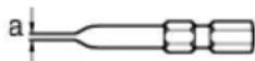
Optional accessories are subject to change without notice.
APPLICATIONS
○By combined actions of ROTATION and IMPACT: Boring holes in hard surfaces (concrete, marble, granite, tiles, etc.)
○By ROTATIONAL action: Boring holes in metal, wood and plastic. Tightening machine screws, wood screws.
PRIOR TO OPERATION
1. Power source
Ensure that the power source to be utilized conforms to the power requirements specified on the product nameplate.
2. Power switch
Ensure that the power switch is in the OFF position. If the plug is connected to a receptacle while the power switch is in the ON position, the power tool will start operating immediately, inviting serious accident.
3. Extension cord
When the work area is removed from the power source. Use an extension cord of sufficient thickness and rated capacity. The extension cord should be kept as short as practicable.
4. Fitting the drill bit or the driver bit
Fit the drill bit or driver bit into the chuck and use the chuck wrench to secure it, tightening the chuck using each of the three holes in turn.
5. Selecting the appropriate drill bit
○When boring concrete or stone
Use the drill bits specified in the Optional Accessories.
○When boring metal or plastic
Use an ordinary metalworking drill bit.
○When boring wood
Use an ordinary woodworking drill bit. However, when drilling 6.5 mm or smaller holes, use a metalworking drill bit.
6. Selecting the driver bit
Screw heads or bits will be damaged unless a bit appropriate for the screw diameter is employed to drive in the screws.
7. Confirm the direction of bit rotation (Fig. 1)
The bit rotates clockwise (viewed from the rear side) by pushing the R-side of the reversing switch lever. The L-side of the lever is pushed to turn the bit counterclockwise.
CAUTION
Never change the direction of bit rotation while operating. Turn the power switch OFF before changing the direction of bit rotation: otherwise, burning of the motor will result.
Always use the impact screw drill with clockwise rotation, when using it as an impact drill.
8. Fixing the side handle
Loosen the knob bolt on the side handle, and attach the side handle to the gear cover in a position convenient for drilling. Match the projecting part of the handle to the groove on the gear cover, and firmly tighten the knob bolt. To remove the side handle, loosen the knob bolt and rotate the handle.
To attach a depth gauge on the side handle, insert the gauge into the U-shaped groove on the side handle, adjust the position of the depth gauge in accordance with the desired depth of the hole, and firmly tighten the knob bolt.
9. IMPACT to ROTATION changeover (Fig. 2)
The Impact Screw Drill can be switched from IMPACT (impact plus rotation) to ROTATION (rotation only) by sliding the change plate. When boring concrete, stone, tile or similar hard materials, sliding the change plate to IMPACT side. The drill head impacts against the material while continuing to rotate.
When boring metal, wood or plastic or tightening the screw, sliding the change plate to ROTATION side. The drill rotates as an ordinary electric drill. CAUTION
☐Do not use the Impact Screw Drill in the IMPACT function if the material can be bored by rotation only. Such action will not only reduce drill efficiency, but may also damage the drill tip.
○The change plate may not slide smoothly when changing from impact drill mode to drill mode (Fig. 2-③).
In this case, switch ON and operate the machine for few seconds.
The spindle shaft will then be pushed forward, and the change plate can be moved smoothly.
10. High-speed/Low-speed changeover
To change speed, rotate the gear shift dial as indicated by the arrow in Fig. 3. The numeral "1" engraved on the drill body denotes low speed, the numeral "2" denotes high speed.
PRACTICAL HANDLING PROCEDURES
1. Speed adjustment and switch operation
☐The drill speed can be adjusted from 0 through full speed by regulating the trigger-squeezing force. The more the trigger is squeezed, the faster the drill rotates. When the trigger is squeezed fully, the speed is the maximum.
○Pulling the trigger switch and pushing the stopper, it keeps the switched-on condition which is convenient for continuous running. When switching off, the stopper can be disconnected by pulling the trigger again.
2. When using as a Drill or an Impact Drill
(1) Pressing force of the drill
You cannot drill holes more quickly even if you press the drill with a stronger force than necessary. It not only damages tip of drill bits and decreases the efficiency of operation, but also shortens the life of the drill.
(2) In case of penetrating holes
Drill bits can be broken when the material being drilled is penetrated. It is important to decrease pressing force just before penetrating.
CAUTION
In continuous operation, conduct no-load operation for five seconds after completing a drilling job.
(3) When a thick drill bit is used
Your arm is subjected to larger reaction force when a thicker drill bit is used. Be careful not to be moved by the reaction force. For this, establish a foothold, hold the unit tightly with both hands perpendicularly to the material being drilled.
3. When driving machine screws
When the trigger switch is pressed, the motor starts. The drill rotates by attaching the bit to the groove of screw head, and by pushing the head together with the driver main body, it tightens the screw.
CAUTIONS
Exercise care not to excessively prolong driving time, otherwise, the screws may be damaged by excessively force.
○Apply the screwdriver perpendicularly to the screw head when driving a screw; otherwise, the screw head or bit will be damaged, or driving force will not be fully transferred to the screw.
4. When driving wood screws
(1) Selecting a suitable driver bit
Employ plus-head screws, if possible, since the driver bit easily slips off the heads of minus-head screws.
(2) Driving in wood screws
○Prior to driving in wood screws, make pilot holes suitable for them in the wooden board. Apply the bit to the screw head grooves and gently drive the screws into the holes.
○After rotating the screwdriver at low speed for a while until a wood screw is partly driven into the wood, squeeze the trigger more strongly to obtain the optimum driving force.
CAUTION
Exercise care in preparing a pilot hole suitable for the wood screw taking the hardness of the wood into consideration. Should the hole the excessively small or shallow, requiring much power to drive the screw into it, the thread of the wood screw may sometimes be damaged.
MAINTENANCE AND INSPECTION
1. Inspecting the driver bit
Since continued use of a worn driver bit will damage screw heads, replace the driver bit as soon as excessive wear is noticed.
2. Inspecting the drill bit
Continued use of a worn and/or damaged drill bit will result in reduced drilling efficiency and may seriously overload the drill motor. Inspect the drill bit frequently and replace it as necessary.
3. Inspecting the mounting screws
Regularly inspect all mounting screws and ensure that they are properly tightened. Should any of the screws be loose, retighten them immediately. Failure to do so could result in serious hazard.
4. Inspecting the carbon brushes (Fig. 4)
The motor employs carbon brushes which are consumable parts. Since an excessively worn carbon brush can result in motor trouble, replace the carbon brush with a new one having the same carbon brush No. shown in the figure when it becomes worn to or near the "wear limit". In addition, always keep carbon brushes clean and ensure that they slide freely within the brush holders.
5. Procedure of disassembling and reassembling the handle for replacing a carbon brush, power supply cord, etc. (Fig. 3 and 8)
○Disassembling
(1) Loosen ⑫ three D4 · 16 tapping screws on the handle (A). (Fig. 8)
(2) Turn over the body and loosen ⑫ two D4 · 16 tapping screws on the handle (B). (Fig. 3)
(3) Then remove the handle (B).
○Reassembling
Reassembling can be accomplished by following procedure of disassembling in reverse.
CAUTION
(1) When disassembling, be sure to remove the handle (B). If the handle (A) is removed, the internal wiring in the handle will be damaged.
(2) When reassembling, be sure that the internal wiring is not prinched by the handle or does not come in contact with the rotating parts of the motor.
If the internal wiring is pinched by the handle or comes in contact with the rotating parts of the motor, a serious danger of electric shock to the operator will be created.
6. Replacing a carbon brush (Fig. 5)
○Disassembling
(1) Remove the handle (B) according to aforesaid "5. Procedure of disassembling and reassembling the handle for replacing a carbon brush, power supply cord, etc. (Fig. 3 and 8)."
(2) Lift out the brush holder together with the carbon brush.
(3) Withdraw the brush terminal, and remove the carbon brush from the brush holder.
○Reassembling
(1) Place a new carbon brush into the brush holder, and connect the brush terminal to the carbon brush.
(2) Return the brush holder and other parts to their original positions, as illustrated in Fig. 5.
(3) Ensure that the lead wire and other parts are properly positioned.
(4) Reassemble the handle (B) according to aforesaid "5. Procedure of disassembling and reassembling the handle for replacing a carbon brush, power supply cord, etc. (Fig. 3 and 8)."
7. Maintenance of the motor
The motor unit winding is the very "heart" of the power tool. Exercise due care to ensure the winding does not become damaged and/or wet with oil or water.
NOTE
Due to HITACHI's continuing program of research and development, the specifications herein are subject to change without prior notice.
Information concerning airborne noise and vibration The measured values were determined according to EN50144.
The typical A-weighted sound pressure level: 102 dB (A) (DV20V2·DV20V3·DV20T) 98 dB (A) (DV14V)
The typical A-weighted sound power level: 115 dB (A) (DV20V2·DV20V3·DV20T) 111 dB (A) (DV14V)
Wear ear protection.
The typical weighted root mean square acceleration value: 14,0 m/s ^2 (DV20V2·DV20V3·DV20T) 13,0 m/s ^2 (DV14V)
natural_image
Line drawing of a quill pen in an inkwell (no text or symbols)
natural_image
Line drawing of a quill pen in an inkwell (no text or symbols)
natural_image
Line drawing of a quill pen in an inkwell (no text or symbols)| Svenska | Suomi | ||
| EF-DEKLARATION BETRÄFFANDE LIKFORMIGHETVi tillkännagivr med eget ansvar att denna produkt överensstämmer med standard eller standardiserat dokument EN60335, EN55014, EN60555 och EN50082-1 i enlighet med råddirektiven 73/23/E∅S och 89/336/E∅S.* Denna deklaration gäller för CE-märkningen på produkten. | EY-ILMOITUS YHDENMUKAISUUDESTAYksinomaisella vastuudella vakuutamme, ettäätmätuote vastaa normeja tai normitettuja dokumentteja EN60335, EN55014, EN60555 ja EN50082-1 yhteisön ohjeiden 73/23/ETY ja 89/336/ETY mukaisesti.* Tämä ilmoitus sovelletaan tuotekohtaiseen CE-merkintään. | ||
| Dansk | English | ||
| EF-DEKLARATION OM ENSARTETHEDVi erklærer os fuldstændige ansvarlige for, at dette produkt modsvarer gældende standard eller de standardiserede dokumenter EN60335, EN55014, EN60555 og EN50082-1 i overensstemmelse med EF-direktiver 73/23/E∅F og 89/336/E∅F.* Denne erklæring qælder produkter, der er mærket med CE. | EC DECLARATION OF CONFORMITYWe declare under our sole responsibility that this product is in conformity with standards or standardized documents EN60335, EN55014, EN60555 and EN50082-1 in accordance with Council Directives 73/23/EEC and 89/336/EEC.* This declaration is applicable to the product affixed CE marking. | ||
| Norsk | |||
| EF's ERKLÆRING OM OVERENSSTEMMELSEVi erklærer herved at vi påtar oss eneansvaret for at dette produktet er i overensstemmelse med normer eller standardiserte dokumenter EN60335, EN55014, EN60555 og EN50082-1 i samsvar med Rådsdirektiver 73/23/E∅S og 89/336/E∅S.* Denne erklæringen gjelder produktets påklistrede CE-merking. | |||
Hitachi Power Tools Europe GmbHSiemensring 34, 47877 Willich, F. R. Germany Hitachi Koki Co., Ltd.Nippon Building, 6-2, Ohtemachi 2-chome, Chiyoda-ku, Tokyo, Japan  K. Mitsuishi K. Mitsuishi | |||
Hitachi Koki Co., Ltd.
- SÄKERHETSFÖRESKRIFTER FÖR ELVERKTYG
- WARNING!
- GENERELLE FORSIGTIGHEDSREGLER
- ADVARSEL!
- VEDLIKEHOLD OG INSPEKSJON
- For safe operations:
- English
- PRECAUTIONS ON USING IMPACT DRILL
- STANDARD ACCESSORIES
- OPTIONAL ACCESSORIES (sold separately)
- APPLICATIONS
- PRIOR TO OPERATION
- Power source
- Power switch
- Extension cord
- Fitting the drill bit or the driver bit
- Selecting the appropriate drill bit
- Selecting the driver bit
- Confirm the direction of bit rotation (Fig. 1)
- CAUTION
- Fixing the side handle
- IMPACT to ROTATION changeover (Fig. 2)
- High-speed/Low-speed changeover
- PRACTICAL HANDLING PROCEDURES
- Speed adjustment and switch operation
- When using as a Drill or an Impact Drill
- When driving machine screws
- CAUTIONS
- When driving wood screws
- MAINTENANCE AND INSPECTION
- Inspecting the driver bit
- Inspecting the drill bit
- Inspecting the mounting screws
- Inspecting the carbon brushes (Fig. 4)
- Procedure of disassembling and reassembling the handle for replacing a carbon brush, power supply cord, etc. (Fig. 3 and 8)
- ○Disassembling
- ○Reassembling
- Replacing a carbon brush (Fig. 5)
- Maintenance of the motor
- NOTE
- Hitachi Koki Co., Ltd.
Brand : HITACHI
Model : DV 20V2
Category : Drill