
FDV 20VB - Drill HITACHI - Free user manual and instructions
Find the device manual for free FDV 20VB HITACHI in PDF.


| Product Type | Cordless Drill |
| Brand | Hitachi |
| Model | FDV 20VB |
| Power Source | Battery-powered |
| Battery Voltage | 20V Max (18V nominal) |
| Battery Type | Lithium-ion |
| Chuck Type | Keyless |
| Chuck Size | 1/2 inch (13 mm) |
| No-Load Speed (Low) | 0-600 RPM |
| No-Load Speed (High) | 0-2000 RPM |
| Max Torque | 50 Nm |
| Drilling Capacity (Steel) | 10 mm |
| Drilling Capacity (Wood) | 25 mm |
| Weight (with battery) | 1.2 kg |
| Dimensions (L x H) | 200 x 200 mm |
| Variable Speed Trigger | Yes |
| Forward/Reverse Switch | Yes |
| LED Work Light | Yes |
| Belt Clip | Included |
| Overload Protection | Yes |
| Soft Grip Handle | Yes |
| Included Accessories | Drill, battery, charger, case |
| Maintenance | Keep vents clean, check chuck tightness |
| Safety Precautions | Wear eye protection, avoid moisture |
| Spare Parts Available | Battery, chuck, carbon brushes |
Frequently Asked Questions - FDV 20VB HITACHI
User questions about FDV 20VB HITACHI
0 question about this device. Answer the ones you know or ask your own.
Ask a new question about this device
Download the instructions for your Drill in PDF format for free! Find your manual FDV 20VB - HITACHI and take your electronic device back in hand. On this page are published all the documents necessary for the use of your device. FDV 20VB by HITACHI.
USER MANUAL FDV 20VB HITACHI
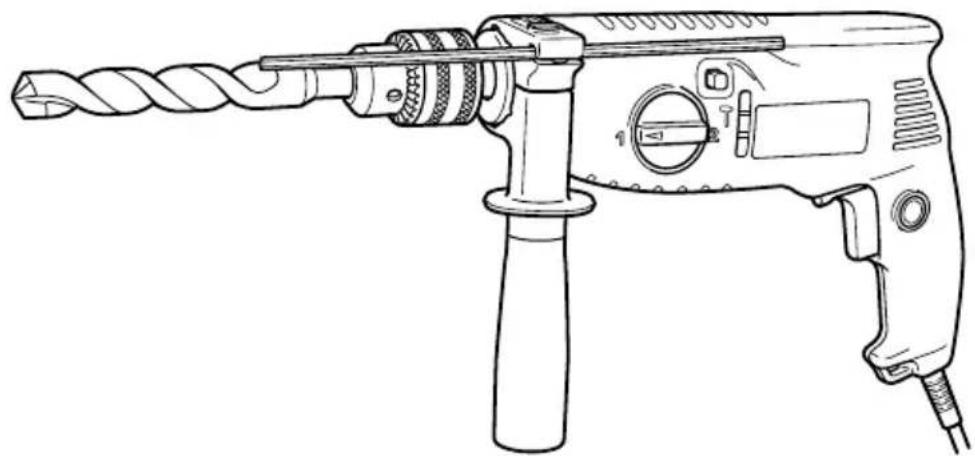
Slagborr Slagboremaskine Slagboremaskin Iskuporakone Impact Drill
FDV 20VB
natural_image
Line drawing of a manual drill bit with handle and screwdriver (no text or symbols)Read through carefully and understand these instructions before use.

Bruksanvisning
Brugsanvisning
Bruksanvisning
Käyttöohjeet
Handling Instructions
| A | B | C | D | A | B | C | D |
| 1 | 995-344 | 1 M6·25 | 29 | 875-638 | 1 S-12 | ||
| 2 | 987-576 | 1 | 30 | —— | 1 | ||
| 3 | 1 | —— | 1 13VLRB-D “2” | 31 | —— | 1 | |
| 3 | 2 | 319-546 | 1 13VLRE-N | 32 | 981-373 | 2 | |
| 4 | 319-601 | 1 | 33 | 307-217 | 1 | ||
| 5 | 608-VVM | 2 608VVC2PS2L | 34 | 960-266 | 1 | ||
| 6 | 319-605 | 1 | 35 | 305-812 | 2 D4·16 | ||
| 7 | 319-604 | 2 | 36 | 500-409Z | 1 | ||
| 8 | 963-226 | 1 | 37 | 994-273 | 1 | ||
| 9 | 319-603 | 1 | 38 | 302-488 | 1 | ||
| 10 | 319-602 | 1 | 39 | 319-642 | 1 | ||
| 11 | 608-DDM | 1 608DDC2PS2L | 501 | 303-659 | 1 | ||
| 12 | 1360-548U | 1 | 110V-115V“5,1,3” | 502 | 303-709 | 1 | |
| 12 | 2 | 360-548E | 1 220V-230V | 503 | 319-616 | 1 | |
| 12 | 3 | 360-548F | 1 240V | ||||
| 13 | 319-609 | 1 | |||||
| 14 | 1 | 340-496C | 1 110V-115V | ||||
| 14 | 2 | 340-496E | 1 220V-230V | ||||
| 14 | 3 | 340-496F | 1 240V | ||||
| 15 | 303-655 | 1 | |||||
| 16 | 319-612 | 1 | |||||
| 17 | 319-611 | 1 | |||||
| 18 | 303-656 | 1 | |||||
| 19 | 319-644 | 1 | |||||
| 20 | —— | 1 | |||||
| 21 | 302-086 | 9 D4·20 | |||||
| 22 | 319-607 | 1 | |||||
| 23 | 999-041 | 2 | |||||
| 24 | 955-203 | 2 | |||||
| 25 | 1 | 314-916 | 1 100V-115V | ||||
| 25 | 2 | 314-921 | 1 220V-240V | ||||
| 26 | 319-643 | 1 | |||||
| 27 | 319-606 | 1 | |||||
| 28 | 319-608 | 1 |

1

natural_image
Illustration of hands using a drill bit to adjust a mechanical component (no text or symbols present)2

3

4

5

6

7
8

natural_image
Diagram of a drill bit cutting through a pile with a tool, showing no text or symbols
natural_image
Diagram of a drill bit milling into a pile with motion arrows indicating process (no text or symbols)| Svenska | Dansk Norsk | ||
| 1Borrchuck med chucknyckel Borpatron | med bornøgle Borpatron med chuck-nökkel | ||
| 2Hylsa Indsatspatron Mansjett | |||
| 3Låskrage Låsemuffe Låsekrans | |||
| 4Stoppring Sikringsring Låsering | |||
| 5Backomkopplare | Omskifterarm til modsat omdrejning | Reverseringshendel | |
| 6Omkopplingsspak Omskiftergreb Skiftehendel | |||
| 7Rotation med Slag Rotation + Slag Rotasjon + Slag | |||
| 8Rotation Rotation Rotasjon | |||
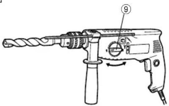
| 9 | Hastighetsväljare | Hastighedsomskifterarm | Girspak |
VEDLIKEHOLD OG INSPEKSJON
Read all instructions
Failure to follow all instructions listed below may result in electric shock, fire and/or serious injury.
The term “power tool” in all of the warnings listed below refers to your mains operated (corded) power tool or battery operated (cordless) power tool.
SAVE THESE INSTRUCTIONS
1) Work area
a) Keep work area clean and well lit.
Cluttered and dark areas invite accidents.
b) Do not operate power tools in explosive atmospheres, such as in the presence of flammable liquids, gases or dust.
Power tools create sparks which may ignite the dust of fumes.
c) Keep children and bystanders away while operating a power tool.
Distractions can cause you to lose control.
2) Electrical safety
a) Power tool plugs must match the outlet.
Never modify the plug in any way.
Do not use any adapter plugs with earthed (grounded) power tools.
Unmodified plugs and matching outlets will reduce risk of electric shock.
b) Avoid body contact with earthed or grounded surfaces such as pipes, radiators, ranges and refrigerators.
There is an increased risk of electric shock if your body is earthed or grounded.
c) Do not expose power tools to rain or wet conditions.
Water entering a power tool will increase the risk of electric shock.
d) Do not abuse the cord. Never use the cord for carrying, pulling or unplugging the power tool. Keep cord away from heat, oil, sharp edges or moving parts.
Damaged or entangled cords increase the risk of electric shock.
e) When operating a power tool outdoors, use an extension cord suitable for outdoor use.
Use of a cord suitable for outdoor use reduces the risk of electric shock
3) Personal safety
a) Stay alert, watch what you are doing and use common sense when operating a power tool. Do not use a power tool while you are tired or under the influence of drugs, alcohol or medication.
A moment of inattention while operating power tools may result in serious personal injury.
b) Use safety equipment. Always wear eye protection.
Safety equipment such as dust mask, non-skid safety shoes, hard hat, or hearing protection used for appropriate conditions will reduce personal injuries.
c) Avoid accidental starting. Ensure the switch is in the off position before plugging in.
Carrying power tools with your finger on the switch or plugging in power tools that have the switch on invites accidents.
d) Remove any adjusting key or wrench before turning the power tool on.
A wrench or a key left attached to a rotating part of the power tool may result in personal injury.
e) Do not overreach. Keep proper footing and balance at all times.
This enables better control of the power tool in unexpected situations.
f) Dress properly. Do not wear loose clothing or jewellery. Keep your hair, clothing and gloves away from moving parts.
Loose clothes, jewellery or long hair can be caught in moving parts.
g) If devices are provided for the connection of dust extraction and collection facilities, ensure these are connected and properly used.
Use of these devices can reduce dust related hazards.
a) Do not force the power tool. Use the correct power tool for your application.
The correct power tool will do the job better and safer at the rate for which it was designed.
b) Do not use the power tool if the switch does not turn it on and off.
Any power tool that cannot be controlled with the switch is dangerous and must be repaired.
c) Disconnect the plug from the power source before making any adjustments, changing accessories, or storing power tools.
Such preventive safety measures reduce the risk of starting the power tool accidentally.
d) Store idle power tools out of the reach of children and do not allow persons unfamiliar with the power tool or these instructions to operate the power tool.
Power tools are dangerous in the hands of untrained users.
e) Maintain power tools. Check for misalignment or binding of moving parts, breakage of parts and any other condition that may affect the power tools operation.
If damaged, have the power tool repaired before use.
Many accidents are caused by poorly maintained power tools.
f) Keep cutting tools sharp and clean.
Properly maintained cutting tools with sharp cutting edges are less likely to bind and are easier to control.
g) Use the power tool, accessories and tool bits etc., in accordance with these instructions and in the manner intended for the particular type of power tool, taking into account the working conditions and the work to be performed.
Use of the power tool for operations different from intended could result in a hazardous situation.
4) Power tool use and care
5) Service
a) Have your power tool serviced by a qualified repair person using only identical replacement parts.
This will ensure that the safety of the power tool is maintained.
PRECAUTION
Keep children and infirm persons away. When not in use, tools should be stored out of reach of children and infirm persons.
PRECAUTIONS ON USING IMPACT DRILL
- Wear ear protectors with impact drills.
Exposure to noise can cause hearing loss. - Use auxiliary handles supplied with the tool. Loss of control can cause personal injury.
- Before drilling into walls, ceilings or floors, ensure that there are no concealed power cables inside.
SPECIFICATIONS
- When boring concrete or similar hard materials in IMPACT mode, set the bit rotation switch lever to the R-side. (Fig. 8)
- Avoid tightening work of screws, bolts, and nuts; otherwise, rotating sections may be stopped all of a sudden, resulting in the malfunction of the main body and risk of injury.
| Voltage (by areas)* (110V, 115V, 120V, 127V, 220V, 230V, 240V) | |||
| Power input 750W* | |||
| Speed change 1 2 | |||
| No load speed 0 – 1300 min | -1 | 0 – 3000 min-1 | |
| Capacity Concrete | Steel 13 mm 8 mm | ||
| 20 mm 13 mm | |||
| Wood | 40 mm 25 mm | ||
| Full load impact rate | 15000 min-1 | 35000 min-1 | |
| Weight (without cord) | 2.2 kg | ||
* Be sure to check the nameplate on product as it is subject to change by areas.
STANDARD ACCESSORIES
(1) Chuck Wrench (Spec. only for chuck fitted with chuck wrench).... 1
(2) Side Handle.... 1
(3) Depth Gauge 1
(4) Plastic Case 1
Standard accessories are subject to change without notice.
OPTIONAL ACCESSORIES (sold separately)
○Impact Drill Bit (for concrete)
3.2 mm - 20 mm dia.
Optional accessories are subject to change without notice.
APPLICATIONS
○By combined actions of ROTATION and IMPACT: Boring holes in hard materials (concrete, marble, granite, tiles, etc.)
○By ROTATIONAL action: Boring holes in metal, wood and plastic.
PRIOR TO OPERATION
1. Power source
Ensure that the power source to be utilized conforms to the power requirements specified on the product nameplate.
2. Power switch
Ensure that the power switch is in the OFF position. If the plug is connected to a receptacle while the power switch is in the ON position, the power tool will start operating immediately, inviting serious accident.
3. Extension cord
When the work area is removed from the power source. Use an extension cord of sufficient thickness
and rated capacity. The extension cord should be kept as short as practicable.
4. Mounting and dismounting of the bit.
For Drill chuck with chuck wrench (Fig. 1)
Fit the drill bit into the chuck and use the chuck wrench to secure it, tightening the chuck by each of the three holes in turn.
For keyless chuck (Fig. 2, 3)
(1) Mounting the bit
Turn the lock collar in the direction “AUF. RELEASE” and open the chuck. After Inserting the drill bit Into the chuck as far it will go, turn the lock collar in the “GRIP.ZU” direction. Grip the retaining ring and close the chuck by turning the sleeve clockwise as viewed from the front.
(2) Dismounting the bit
Turn the lock collar in the direction "AUF. RELEASE" to release the shucking force. Grip the retaining ring and open the chuck by turning the sleeve counterclockwise.
NOTE
When the sleeve does not become loose any further, fix a regular spanner to spindle, hold regular spanner firmly, then turn the sleeve to loosen by hand. (Fig. 4)
5. Selecting the appropriate drill bit
○When boring concrete or stone Use the drill bits specified in the Optional Accessories.
○When boring metal or plastic Use an ordinary metalworking drill bit.
○When boring wood Use an ordinary woodworking drill bit. However, when drilling 6.5 mm or smaller holes, use a metalworking drill bit.
6. Confirm the direction of bit rotation (Fig. 5)
The bit rotates clockwise (viewed from the rear side) by pushing the R-side of the reversing switch lever. The L-side of the lever is pushed to turn the bit counterclockwise.
CAUTION
○Never change the direction of bit rotation during operation.
Turn the power switch OFF before changing the direction of bit rotation; otherwise, the motor will burn.
○Always use with clockwise rotation, when using it as an impact drill.
7. Side handle attachment
Attach the side handle to the mounting part. Rotate the side handle grip in a clockwise direction to secure it.
Set the side handle to a position that is suited to the operation and then securely tighten the side handle grip.
8. IMPACT to ROTATION changeover (Fig. 6)
The impact drill can be switched from IMPACT (impact plus rotation) to ROTATION (rotation only) by simply sliding the change knob. When boring concrete, stone, tile or similar board materials, slide the change knob right. The drill head impacts against the material while continuing to rotate.
When boring metal, wood or plastic, slide the change knob fully to the left. The drill simply rotates as an ordinary electric drill.
CAUTION
Do not use the impact drill in the IMPACT mode if the material can be bored by rotation only. Such action will not only reduce drill efficiency, but may also damage the drill tip.
When changing over, ensure the change knob is slide as far as it will go.
9. High-spped/Low-speed changeover
To change speed, rotate the gear shift lever as indicated by the arrow in Fig. 7. The numeral “1” engraved on the drill body denotes low speed, the numeral “2” denotes high speed.
PRACTICAL HANDLING PROCEDURES
1. Speed adjustment and switch operation
☐The drill speed can be adjusted from 0 through full speed by regulating the trigger-squeezing force. The more the trigger is squeezed, the faster the drill rotates. When the trigger is squeezed fully, the speed is the maximum.
○Pulling the trigger switch and pushing the stopper, keeps the switched-on condition which is convenient for continuous running. When switching off, the stopper can be disconnected by pulling the trigger again.
CAUTION
Drill at a maximum rotation speed when drilling wooden materials.
2. When using as a Drill or an Impact Drill
(1) Pressing force of the drill
You cannot drill holes more quickly even if you press the drill with a stronger force than necessary. It not only damages tip of drill bit and decreases the efficiency of operation, but also shortens the life of the drill tip.
(2) In case of penetrating holes
Drill bits can be broken when the material being drilled is penetrated. It is important to decrease pressing force just before penetrating.
CAUTION
In continuous operation, conduct no-load operation for five seconds after completing a drilling job.
(3) When a thick drill bit is used
Your arm is subjected to larger reaction force when a thicker drill bit is used. Be careful not to be moved by the reaction force. For this, establish a foothold, hold the unit tightly with both hands perpendicularly to the material being drilled.
3. Using a large diameter drill bit
The larger the drill bit diameter, the larger the reactive force on your arm. Be careful not to lose control of the drill because of this reactive force. To maintain firm control, establish a good foothold, hold the drill tightly with both hands, and ensure that the drill is vertical to the material being drilled.
4. When drilling completely through the material
When the drill bit bores completely through the material, careless handling often results in a broken, drill bit or damage to the drill body itself due to the sudden movement of the drill. Always be alert and ready to release pushing force when drilling through the material.
MAINTENANCE AND INSPECTION
1. Inspecting the drill bit
Continued use of a worn and/or damaged drill bit will result in reduced drilling efficiency and may seriously overload the drill motor. Inspect the drill bit frequently and replace it as necessary.
2. Inspecting the mounting screws
Regularly inspect all mounting screws and ensure that they are properly tightened. Should any of the screws be loose, retighten them immediately. Failure to do so could result in serious hazard.
3. Maintenance of the motor
The motor unit winding is the very “heart” of the power tool. Exercise due care to ensure the winding does not become damaged and/or wet with oil or water.
4. Servicing
Consult an authorized Service Center in the event of power tool failure.
5. Service parts list
A: Item No.
B: Code No.
C: No. Used
D: Remarks
CAUTION
Repair, modification and inspection of Hitachi Power Tools must be carried out by an Hitachi Authorized Service Center.
This Parts List will be helpful it presented with the tool to the Hitachi Authorized Serivde Center when requesting repair or other maintenance.
In the operation and maintenance of power tools, the safety regulations and standards prescribed in each country must be observed.
MODIFICATIONS:
Hitachi Power Tools are constantly being improved and modified to incorporate the latest technological advancements.
Accordingly, some parts (i.e. code numbers and/or design) may be changed without prior notice.
NOTE
Due to HITACHI's continuing program of research and development, the specifications herein are subject to change without prior notice.
Information concerning airborne noise and vibration
The measured values were determined according to EN60745 and declared in accordance with ISO 4871.
Measured A-weighted sound power level: 113 dB (A) Measured A-weighted sound pressure level: 102 dB (A) Uncertainty KpA: 3 dB (A).
Wear ear protection.
The typical weighted root mean square acceleration value: 14.0 m/s^2 .

natural_image
Symbol of a trash bin crossed with no text or numbers, representing waste sorting or restriction (no text present)Svenska
Only for EU countries
Do not dispose of electric tools together with household waste material!
In observance of European Directive 2002/96/EC on waste electrical and electronic equipment and its implementation in accordance with national law, electric tools that have reached the end of their life must be collected separately and returned to an environmentally compatible recycling facility.
| Svenska | Suomi | ||
| EF-DEKLARATION BETRÄFFANDE LIKFORMIGHETVi tillkännagiver med eget ansvar att denna produkt överensstämmer med standard eller standardiserat dokument EN60745, EN55014 och EN61000-3 i enlighet med råddirektiven 73/23/E∅S, 89/336/E∅S och 98/37/EF.Denna deklaration gäller för CE-märkningen på produkten. | EY-ILMOITUS YHDENMUKAISUUDESTAYksinomaisella vastuudella vakuutamme, että tämä tuote vastaa normeja tai normitettuja dokumentteja EN60745, EN55014 ja EN61000-3 yhteisön ohjeiden 73/23/ETY, 89/336/ETY ja 98/37/EY mukaisesti.Tämä ilmoitus sovelletaan tuotekohtaiseen CE-merkintään. | ||
| Dansk | English | ||
| EF-DEKLARATION OM ENSARTETHEDVi erlkærer os fuldstændige ansvarlige for, at dette produkt modsvarer gældende standard eller de standardiserede dokumenter EN60745, EN55014 og EN61000-3 i overensstemmelse med EF-direktiver 73/23/E∅F, 89/336/E∅S og 98/37/EF.Denne erklæring qælder produkter, der er mærket med CE. | EC DECLARATION OF CONFORMITYWe declare under our sole responsibility that this product is in conformity with standards or standardized documents EN60745, EN55014 and EN61000-3 in accordance with Council Directives 73/23/EEC, 89/336/EEC and 98/37/EC.This declaration is applicable to the product affixed CE marking. | ||
| Norsk | |||
| EF'S ERKLÆRING OM OVERENSSTEMMELSEVierklærerherved at vi påtar oss eneansvaret for at dette produktet er i overensstermmelse med normer eller standardiserte dokumenter EN60745, EN55014 og EN61000-3 i samsvar med Rådsdirektiver 73/23/E∅S, 89/336/E∅S og 98/37/EF.Denne erklæringen gjelder produktets påklistrede CE-merking. | |||
| Representative office in Europe Hitachi Power Tools Europe GmbH Siemensring 34, 47877 Willich 1, F. R. Germany Head office in Japan Hitachi Koki Co., Ltd.Shinagawa Intercity Tower A, 15-1, Konan 2-chome, Minato-ku, Tokyo, Japan | CE 30. 12. 2005H. KatoK. KatoBoard Director | ||

Hitachi Koki Co., Ltd.
- Slagborr Slagboremaskine Slagboremaskin Iskuporakone Impact Drill
- VEDLIKEHOLD OG INSPEKSJON
- Read all instructions
- SAVE THESE INSTRUCTIONS
- 1) Work area
- 2) Electrical safety
- 3) Personal safety
- 4) Power tool use and care
- 5) Service
- PRECAUTION
- PRECAUTIONS ON USING IMPACT DRILL
- STANDARD ACCESSORIES
- OPTIONAL ACCESSORIES (sold separately)
- APPLICATIONS
- PRIOR TO OPERATION
- Power source
- Power switch
- Extension cord
- Mounting and dismounting of the bit.
- For Drill chuck with chuck wrench (Fig. 1)
- For keyless chuck (Fig. 2, 3)
- NOTE
- Selecting the appropriate drill bit
- Confirm the direction of bit rotation (Fig. 5)
- CAUTION
- Side handle attachment
- IMPACT to ROTATION changeover (Fig. 6)
- High-spped/Low-speed changeover
- PRACTICAL HANDLING PROCEDURES
- Speed adjustment and switch operation
- When using as a Drill or an Impact Drill
- Using a large diameter drill bit
- When drilling completely through the material
- MAINTENANCE AND INSPECTION
- Inspecting the drill bit
- Inspecting the mounting screws
- Maintenance of the motor
- Servicing
- Service parts list
- MODIFICATIONS:
- Information concerning airborne noise and vibration
- Svenska
- Hitachi Koki Co., Ltd.
Brand : HITACHI
Model : FDV 20VB
Category : Drill