
RB 24E - Leaf blower HITACHI - Free user manual and instructions
Find the device manual for free RB 24E HITACHI in PDF.

| Product Type | Leaf Blower |
| Brand | Hitachi |
| Model | RB 24E |
| Engine Displacement | 23.9 cc |
| Dry Weight | 5.0 kg |
| Fuel Tank Capacity | 0.6 L |
| Fuel Type | 2-stroke, 89 octane unleaded gasoline mixed with oil (25:1 to 50:1) |
| Spark Plug | NGK BMR7A |
| Air Cleaner | Oiled foam filter system |
| Sound Pressure Level (LpA) | 81.0 dB(A) (ISO22868) / 68.0 dB(A) (ANSI) |
| Sound Power Level (LwA) | 101 dB(A) (measured), 104 dB(A) (guaranteed) |
| Vibration Level | 11.2 m/s² (ISO22867) |
| Idle Speed | 2800-3200 rpm |
| Blowing Pipe Configurations | Straight pipe and fan-headed pipe included |
| Choke System | Manual choke lever (CLOSED/RUN positions) |
| Priming System | Priming bulb for cold starts |
| Cruise Control | Cruise lever for constant throttle |
| Ignition Switch | ON/OFF switch |
| Safety Features | Automatic engine stop if dust cover opened; muffler guard; handle guard |
| Maintenance | Daily: clean exterior, check air intake; Weekly: clean spark plug, air filter; Monthly: clean fuel filter; Quarterly: clean cylinder fins, fan, muffler (dealer recommended) |
| Included Accessories | Straight pipe, fan-headed pipe, dust cover, combi box spanner |
| Optional Accessories | Vacuum attachment kit (RB-HVA) |
| Warranty | Consult local Hitachi service center |
Frequently Asked Questions - RB 24E HITACHI
User questions about RB 24E HITACHI
0 question about this device. Answer the ones you know or ask your own.
Ask a new question about this device
Download the instructions for your Leaf blower in PDF format for free! Find your manual RB 24E - HITACHI and take your electronic device back in hand. On this page are published all the documents necessary for the use of your device. RB 24E by HITACHI.
USER MANUAL RB 24E HITACHI
natural_image
Technical line drawing of a mechanical tool labeled RB24E, showing a cylindrical component with textured ends and a gear-like head (no text or symbols on the diagram itself)
natural_image
Technical line drawing of a mechanical device with labeled part '5' (no text or symbols beyond label)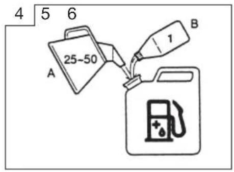
natural_image
Line drawing of a hand using a tool to adjust or install a mechanical component (no text or symbols present)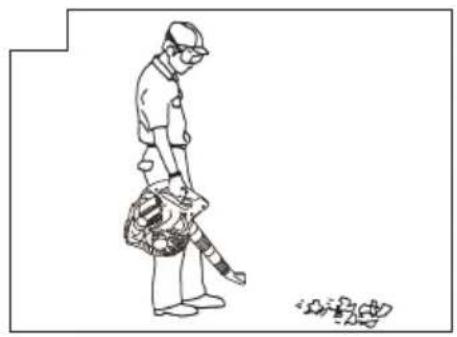
natural_image
Line drawing of a person cleaning a street cleaner with a bag, next to a small pile of debris (no text or symbols)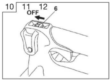
natural_image
Technical line drawing of a mechanical component with hands and a labeled part 'T' (no text or symbols beyond label)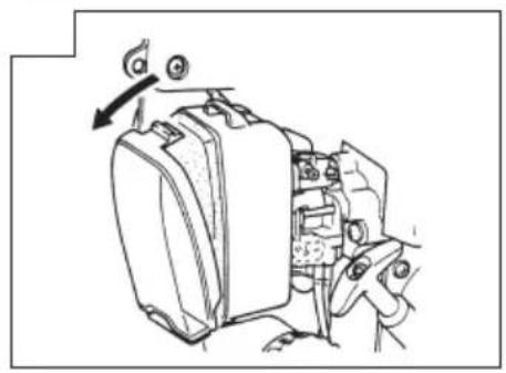
natural_image
Mechanical assembly diagram showing a motor or gear mechanism with no visible text or symbols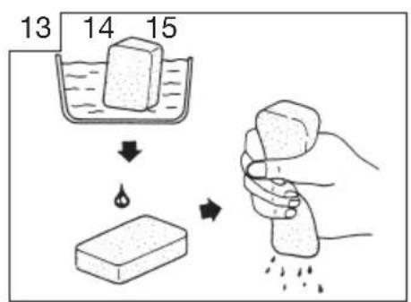
flowchart
graph TD
    A["13: Water in container"] --> B["14: Drop"]
    B --> C["15: Stabilized block"]
    C --> D["16: Disinfection or dust removal"]
natural_image
Technical line drawing of a mechanical device with gears and adjustment knobs (no text or symbols)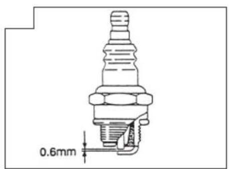
natural_image
Illustration of a closed book with visible page lines and a small number 18 on the cover (no text or symbols beyond the label)natural_image
Isometric line drawing of a closed book with visible page lines and cover (no text or symbols)natural_image
Isometric line drawing of a closed book with visible page lines and cover (no text or symbols)natural_image
Technical line drawings of a screwdriver and a notepad (no text or symbols)NOTE : Some units do not carry them.
| symbols⚠ WARNINGThe engine exhaust from this product contains chemicals known to the State of California to cause cancer, birth defects and other reproductive harm. | |
 | It is important that you read, fully understand and observe the following safety precautions and warnings. Careless or improper use of the unit may cause serious or fatal injury. |
 | Read, understand and follow all warnings and instructions in this manual and on the unit. |
 | Always wear eye, head and ear protectors when using this unit. |
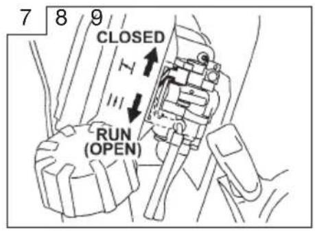
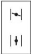 | Explains choke position. Upper sign indicates choke closed and the lower fully open. |
 | WARNING ⚠ DANGERKeep hands off from rotating fan. For vacuum, vacuum pipe and bag must be in place. For blower, dust cover must be securely installed. |
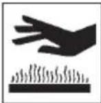 | WARNING ⚠ DANGERHot surfaces; The muffler or catalytic muffler and surrounding cover may become extremely hot. Always keep clear of exhaust and muffler area, otherwise serious personal injury may occur. |
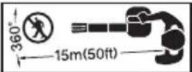 | Keep all children, bystanders and helpers 15 m away from the unit. If anyone approaches you, stop the engine immediately. |
Index
What is what? 2
Warnings and safety instructions 3
Specifications 4
Assembly procedures 5
Operating procedures 5
Maintenance 6
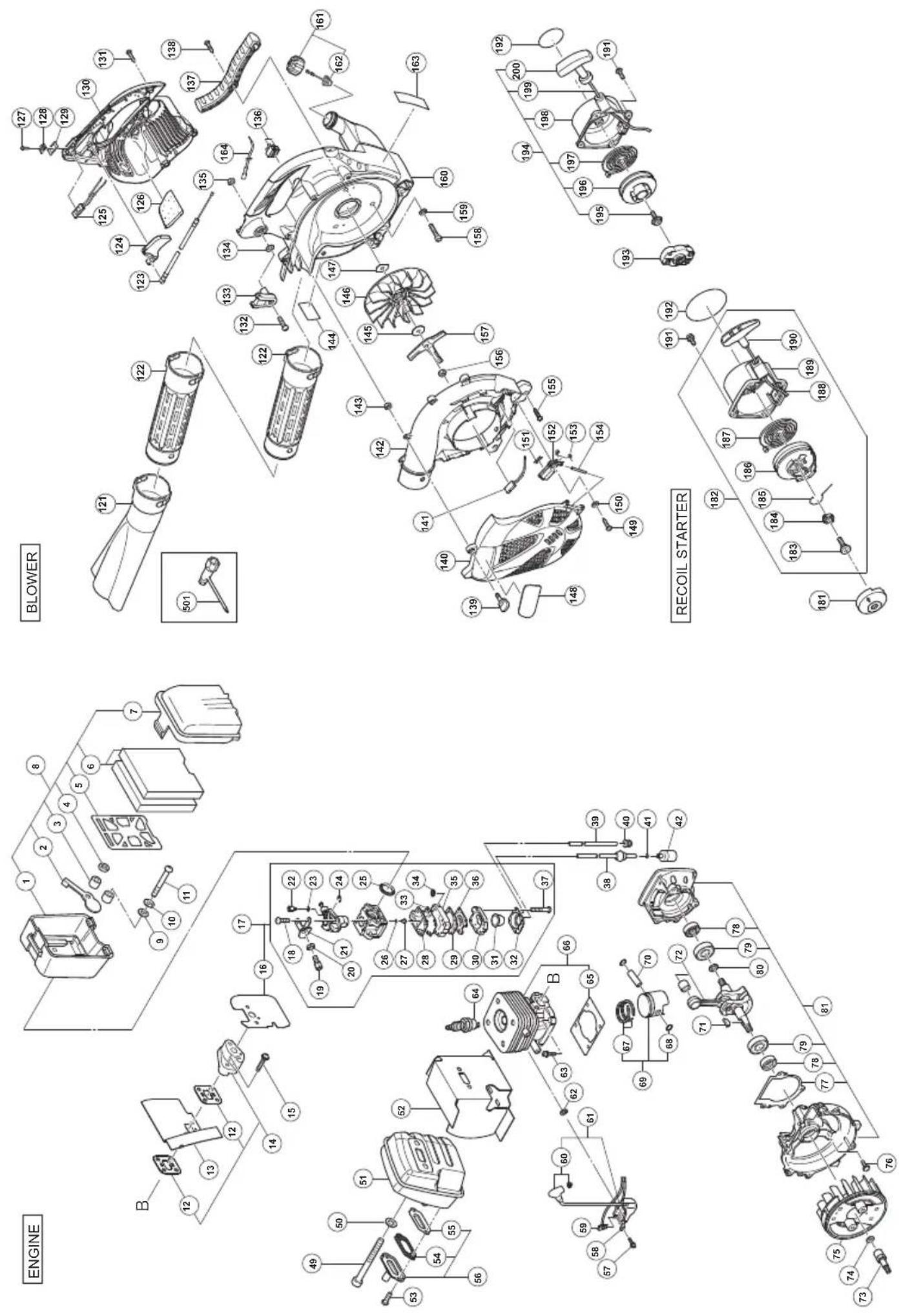
Parts breakdown
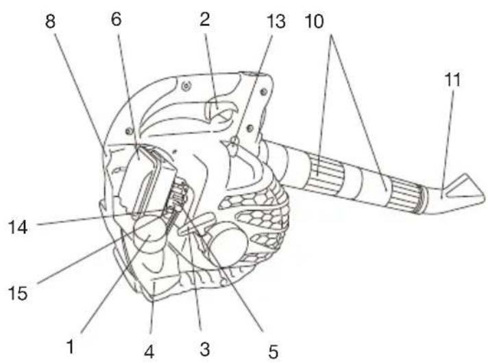
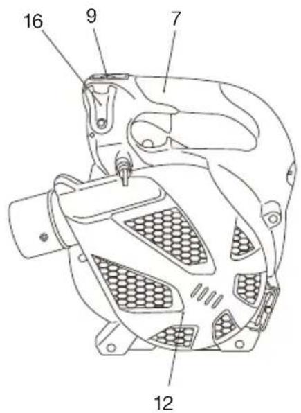
What is what?
Since this manual covers several models, there may be some difference between pictures and your unit. Use the instructions that apply to your unit.
- Fuel cap
- Throttle trigger
- Starter handle
- Fuel tank
- Carburetor
- Air cleaner
- Handle
- Suspension eyelet
- Ignition switch
- Straight pipe
- Fan-headed pipe
- Dust cover
- Spark plug
- Choke lever
- Priming bulb
- Cruise lever
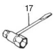
- Combi box spanner
- Handling instructions
natural_image
Isometric illustration of a rectangular sheet with internal lines and a label pointing to the top-right corner (no text or symbols on the sheet itself)Warnings and safety instructions
Pay special attention to statements preceded by the following words:
WARNING
Indicates a strong possibility of severe personal injury or loss of life, if instructions are not followed.
CAUTION
Indicates a possibility of personal injury or equipment damage, if instructions are not followed.
NOTE
Helpful information for correct function and use.
Operator safety
- IMPORTANT: A dust filter mask should be worn during operation.
• Always wear a safety face shield or goggles.
- Always wear heavy, long pants, boots and gloves. Do not wear loose clothing, jewelry, short pants, sandals or go barefoot. Secure hair so it is above shoulder length.
- Do not operate this tool when you are tired, ill or under the influence of alcohol, drugs or medication.
- Never let a child or inexperienced person operate the machine.
- Wear hearing protection. Pay attention to your surroundings. Be aware of any bystanders who may be signaling a problem. Remove safety equipment immediately upon shutting off engine.
- Wear head protection.
- Never start or run the engine inside a closed room or building. Breathing exhaust fumes can kill.
- Keep handles free of oil and fuel.
- Keep hands away from moving part or heated area.
- Do not grab or hold the unit by the blow pipe.
- When the unit is turned off make sure the engine has stopped before the unit is set down.
- When operation is prolonged, take a break from time to time so that you may avoid possible Hand-Arm Vibration Syndrome (HAVS) which is caused by vibration.
WARNING
Antivibration systems do not guarantee that you will not sustain Hand-Arm Vibration Syndrome (HAVS) or carpal tunnel syndrome. Therefore, continual and regular users should monitor closely the condition of their hands and fingers. If any of the above symptoms appear, seek medical advice immediately.
WARNING
If you are using any medical electric/electronic devices such as a pacemaker, consult your physician as well as the device manufacturer prior to operating any power equipment.
Unit / machine safety
- Inspect the entire unit/machine before each use. Replace damaged parts. Check for fuel leaks and make sure all fasteners are in place and securely tightened.
- Replace parts that are cracked, chipped or damaged in any way before using the unit/machine.
- Make sure the safety guard is properly attached.
- Keep others away when making carburetor adjustments.
- Use only accessories as recommended for this unit/machine by the manufacturer.
WARNING
Never modify the unit/machine in any way. Do not use your unit/machine for any job except that for which it is intended.
Fuel safety
NOTE
- Empty the fuel tank before storing the tool. It is recommended that the fuel be emptied after each use. If fuel is left in the tank, store so fuel will not leak.
- Fuel contains highly flammable and it is possible to get the serious personal injury when inhaling or spilling on your body. Always pay attention when handling fuel. Always have good ventilation when handling fuel inside building.
- Mix and pour fuel outdoors and where there are no sparks or flames.
- Use a container approved for fuel.
- Do not smoke or allow smoking near fuel or the unit/machine or while using the unit/machine.
- Wipe up all fuel spills before starting engine.
- Move at least 3 m away from fueling site before starting engine.
- Stop engine before removing fuel cap.
- Store unit/machine and fuel in area where fuel vapors cannot reach sparks or open flames from water heaters, electric motors or switches, furnaces. etc.
WARNING
Fuel is easy to ignite or get explosion or inhale fumes, so that pay special attention when handling or filling fuel.
Blowing safety
- Operate power equipment only at reasonable hours-not early in the morning or late at night when people might be disturbed. Comply with times listed in local ordinances. Usual recommendations are 9:00 a.m. to 5:00 p.m., Monday through Saturday.
- Never direct discharge of air toward bystanders nor allow anyone near the area of operation. Use care in directing discharge to avoid glass enclosures, automobiles, etc.
- Stay alert for uneven sidewalks, holes in terrain or other unstable condition when using the tool.
- Take all possible precautions when leaving the tool unattended such as stopping the engine.
- Never operate the tool without guards, blow pipes or other protective device in place. (If so equipped.)
- Use rakes and brooms to loosen debris before blowing.
- Keep others including children, animals, bystanders and helpers outside the 15 m hazard zone. Stop the engine immediately if you are approached.
• Always keep the engine on the right side of your body. (Blower only) - Keep firm footing and balance. Do not over-reach.
- Keep all parts of your body away from the muffler.
• Always carry a first-aid kit when operating any power equipment. - Never start or run the engine inside a closed room or building and/or near inflammable liquids. Breathing exhaust fumes can kill.
Maintenance safety
- Maintain the unit/machine according to recommended procedures.
- Disconnect the spark plug before performing maintenance except for carburetor adjustments.
- Keep others away when making carburetor adjustments.
- Use only genuine HITACHI replacement parts as recommended by the manufacturer.
CAUTION
Do not disassemble the recoil starter. You may get a possibility of personal injury with recoil spring.
Transport and storage
- Carry the unit/machine by hand with the engine stopped and the muffler away from your body.
- Allow the engine to cool, empty the fuel tank, and secure the unit/machine before storing or transporting in a vehicle.
- Empty the fuel tank before storing the unit/machine, It is recommended that the fuel be emptied after each use. If fuel is left in the tank, store so fuel will not leak.
- Store unit/machine out of the reach of children.
- Clean and maintenance the unit carefully and store it in a dry place.
- Make sure engine switch is off when transporting or storing.
If situations occur which are not covered in this manual, take care and use common sense. Contact Hitachi Authorized Service Centers if you need assistance.
Specifications
| MODEL | RB24E |
| Engine Size (m ) | 23.9 |
| Spark Plug | NGK BMR7A |
| Air Cleaner | Oiled foam filter system |
| Dry Weight (kg) | 5.0 |
| Fuel Tank Capacity ( ) | 0.6 |
| Sound pressure level LpA (dB (A)) by ISO22868 | 81.0 |
| Sound pressure level LpA (dB (A)) by ANSI | 68.0 |
| Uncertainty | 0.6 |
| Sound power level LwA (dB (A)) by ISO22868 | 101 |
| Sound power level LwA (dB (A)) by 2000/14/EC | |
| Measured | 101 |
| Guaranteed | 104 |
| Vibration level (m/s ^2 ) by ISO22867 | 11.2 |
| Uncertainty (m/s ^2 ) | 1.5 |
NOTE : Equivalent noise level/vibration level are calculated as the time-weighted energy total for noise/vibration levels under various working conditions with the following time distribution : 1/7 idle, 6/7 racing.
*All data subject to change without notice.
Assembly procedures
WARNING
Make sure the engine is turned off/stopped and not hot before assembly.
Blow pipes to main body (Fig. 1)
Inspect the main body and accessories.
Connect straight pipe (1) and other pipe(s) securely.
Align groove (2) in straight pipe with projection (3) on blower housing (or another pipe) and slide the pipe onto the blower housing (or another pipe).
Rotate the pipe clockwise to lock it into place.
Fan headed pipe to straight pipe (Fig. 2)
- Align groove (2) on the fan headed pipe (4) and projection (3) on 2^nd straight pipe (1) and rotate the fan head in place.
NOTE (Optional)
Vacuum attachment is offered as an optional kit which converts the hand-held blower into a vacuum cleaner.
For installation see optional kit (RB-HVA) manual.
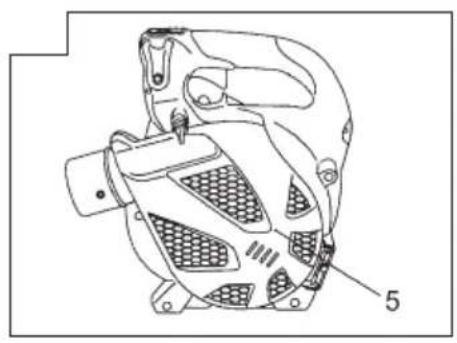
NOTE ; Safety future
If you try to open the dust cover (5) when engine is running, it will automatically stop the engine. (Fig.3)
But never try to open the dust cover (5) when engine is running even with this future, otherwise serious personal injury may occur.
Operating procedures
Fuel (Fig. 4)
WARNING
- This unit is equipped with a two-stroke engine. Always run the engine on fuel, which is mixed with oil. Provide good ventilation, when fueling or handling fuel.
- Fuel contains highly flammable and it is possible to get the serious personal injury when inhaling or spilling on your body. Always pay attention when handling fuel. Always have good ventilation when handling fuel inside building.
Fuel
• Always use branded 89 octane unleaded gasoline.
- Use genuine two-cycle oil or use a mix between 25:1 to 50:1, please consult the oil bottle for the ratio or Hitachi Authorized Service Centers.
- If genuine oil is not available, use an anti-oxidant added quality oil expressly labeled for air-cooled 2-cycle engine use(JASO FC GRADE OIL or ISO EGC GRADE). Do not use BIA or TCW (2-stroke water-cooling type) mixed oil.
- Never use multi-grade oil (10 W/30) or waste oil.
• Always mix fuel and oil in a separate clean container.
Always start by filling half the amount of fuel, which is to be used. Then add the whole amount of oil. Mix (shake) the fuel mixture. Add the remaining amount of fuel.
Mix (shake) the fuel-mix thoroughly before filling the fuel tank.
Fueling
WARNING
- Always shut off the engine and let it cool for a few minutes before refueling.
- Slowly open the fuel tank, when filling up with fuel, so that possible over pressure disappears.
- Tighten the fuel cap carefully, after fueling.
- Always move the unit at least 3 m (10 ft.) from the fueling area before starting.
-
Do not smoke and/or allow flames or sparks near fuel when handling or filling fuel.
-
Always Wash any spilled fuel from clothing immediately with soap.
- Be sure to check any fuel leaking after refueling.
Before fueling, clean the tank cap area carefully, to ensure that no dirt falls into the tank. Make sure that the fuel is well mixed by shaking the container, before fueling.
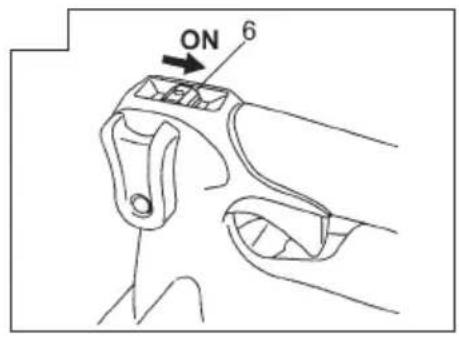
Starting the cold engine
CAUTION
Do not start if the pipe and dust cover are obstructed by the ground or any other object.
- Set ignition switch (6) to ON position. (Fig. 5)
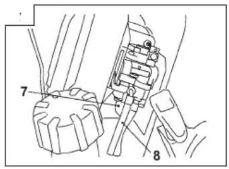
*Push priming bulb (7) several times so that fuel flows through the bulb or return pipe. (8) (Fig. 6) - Set choke lever to CLOSED position. (Fig. 7)
- Pull recoil starter briskly, taking care to keep the handle in your grasp and not allowing it to snap back. (Fig. 8)
- When you hear the engine want to start, return choke lever to RUN position (open). Then pull recoil starter briskly again.
WARNING
- Never start or run the engine inside a closed room or building and/or near the inflammable liquid. Breathing exhaust fumes can kill.
- Do not allow the rope to snap back in and always hold the unit firmly.
NOTE
If engine does not start, repeat procedures from 2 to 4.
- After starting engine, allow the engine about 2-3 minutes to warm up before subjecting it to any load.
Starting the warm engine
Use only 1 and 3 of the starting procedure for cold engine. If the engine does not start, use the same starting procedure as for a cold engine.
Operating blower (Fig. 9)
- A low speed should be used to blow leaves and dry grass.
- A medium speed should be used to clean wet leaves and grass.
- A high speed should be used when moving gravel, dirt or other heavy materials.
WARNING
- Do not direct discharge of air toward people or pet.
- The unit should be operated in a well ventilated area.
- Never perform assembly or disassembly procedures with engine running or serious personal injury may result.
- Never touch muffler, spark plug, or other metallic parts while engine is in running or immediately after shutting off engine.
CAUTION
This blower has been designed and adjusted to be used with all blowing pipes attached (See page 1). It must never be operated without the straight pipe, and fan headed pipe.
NOTE
When you hear or feel strange sound or vibration, stop engine immediately and check if anything blocks fans or pipes, If so, remove it and check for damage.
Stopping (Fig. 10)
Decrease engine speed and run at an idle for a few minutes, then turn off ignition switch.
NOTE
If the engine does not stop, it can be forced to stop by setting the choke lever to CLOSED position.
Before restarting the engine, ask Hitachi Authorized Service Centers for repairs.
Maintenance
MAINTENANCE, REPLACEMENT OR REPAIR OF THE EMISSION CONTROL DEVICES AND SYSTEMS MAY BE PERFORMED BY ANY NON-ROAD ENGINE REPAIR ESTABLISHMENT OR INDIVIDUAL.
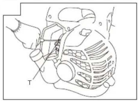
Carburetor adjustment (Fig. 11)
In the carburetor, fuel is mixed with air. When the engine is test run at the factory, the carburetor is basically adjusted. A further adjustment may be required, according to climate and altitude. The carburetor has one adjustment possibility:
T = Idle speed adjustment screw.
Idle speed adjustment (T)
Check that the air filter is clean. If adjustment is required, turn IDLE speed Adjustment Screw (T) close (clockwise) to increase engine speed, open (counterclockwise) to decrease engine speed. Standard Idle rpm is 2800-3200rpm.
CAUTION
The above adjusting procedure must be followed when adjustment is MADE or DAMAGE to engine will occur because of the incorrect condition.
NOTE
Some models sold areas with strict exhaust emission regulation do not have high and low speed carburetor adjustments. Such adjustments may allow the engine to be operated outside of their emission compliance limits. For these models, the only carburetor adjustment is idle speed.
RECOMMENDATION:
CARBURETOR ADJUSTMENT NEEDS THE SKILL OF EXPERIENCED OR WELL TRAINED PEOPLE, OR IS RECOMMENDED TO TAKE THE UNIT TO Hitachi Authorized Service Centers.
Air filter (Fig. 12)
The air filter must be cleaned from dust and dirt in order to avoid:
• Carburetor malfunctions.
- Starting problems.
• Engine power reduction.
- Unnecessary wear on the engine parts.
• Abnormal fuel consumption.
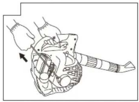
Remove the air cleaner cover by pushing and pulling back the tab on the top. (Fig. 12)
Cleaning the air filter
Clean the cleaner element every day or every 8 hours of operation. More frequent cleaning is recommended under very dusty conditions. Wash the element in liquid detergent and water. Squeeze the element to remove the dirt. Press the element in a dry rag until it is completely dry. Saturate the element in 2 cycle oil. Squeeze the element to distribute the oil completely and to remove any excess oil. Replace the element and install the cover. (Fig. 13) An air filter that has been used for some time cannot be cleaned completely. Therefore, it must regularly be replaced with a new one. A damaged filter must always be replaced.
Fuel filter (Fig. 14)
Drain all fuel from fuel tank and pull fuel filter line from tank. Pull filter element out of holder assembly and rinse element in warm water with detergent. Rinse thoroughly until all traces of detergent are eliminated. Squeeze, do not wring, away excess water and allow element to air dry.
NOTE
If element is hard due to excessive dirt buildup, replace it.
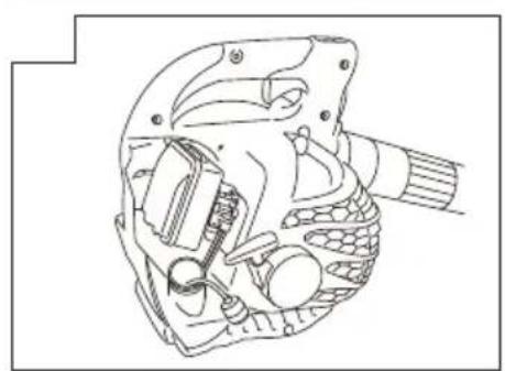
Spark plug (Fig. 15)
The spark plug condition is influenced by:
- An incorrect carburetor setting.
- Wrong fuel mixture (too much oil in the gasoline).
- A dirty air filter.
- Hard running conditions (such as cold weather).
These factors cause deposits on the spark plug electrodes, which may result in malfunction and starting difficulties. If the engine is low on power, difficult to start or runs poorly at idling speed, always check the spark plug first. If the spark plug is dirty, clean it and check the electrode gap. Re-adjust if necessary. The correct gap is 0.6 mm. The spark plug should be replaced after about 100 operation hours or earlier if the electrodes are badly eroded.
NOTE
In some areas, local law requires using a resistor spark plug to suppress ignition signals. If this machine was originally equipped with resistor spark plug, use same type of spark plug for replacement.
Maintenance schedule
Below you will find some general maintenance instructions. For further information please contact Hitachi Authorized Service Centers.
Daily maintenance
- Clean the exterior of the unit.
- Check that the air intake at the dust cover is not clogged.
- Check the dust cover for damage or cracks. Change the cover in case of impacts or cracks.
- Check that nuts and screws are sufficiently tightened.
Weekly maintenance
- Check the starter, especially cord.
- Clean the exterior of the spark plug.
- Remove the spark plug and check the electrode gap. Adjust it to 0.6 ~mm or change the spark plug.
- Clean the air filter.
Monthly maintenance
- Rinse the fuel tank with gasoline, and clean fuel filter.
- Clean the exterior of the carburetor and the space around it.
Quarterly maintenance
- Clean the cooling fins on the cylinder.
- Clean the fan and the space around it.
- Clean the muffler of carbon.
CAUTION
Cleaning of cylinder fins, fan and muffler shall be done by a Hitachi Authorized Service Centers.
NOTE
When ordering the parts to your nearest dealer, please use the item No. showing on the parts breakdown section in this instruction.
MEMO
MEMO
| SE | EF-DEKLARATION BETRÄFFANDE LIKFORMIGHET(Gäller endast Europa)Vi intygar under ensamt ansvar, att denna produkt motsvarar bestämmelsema i direktiven 2006/42/EF, 2004/108/EF och 2000/14/EF.Vi har tagit hänsyn till följande standards.ISO 3864/3744, EN ISO 1200-1/2ISO 9716, EN 27917Bilaga V (2000/14/EF): För information rörande buller, se kapitelbeskrivningen.Den europeiska standardansvarige på Hitachi Koki Europe Ltd. är auktoriserad att utarbeta den tekniska filen.Denna deklaration gäller för CE-märkningen på produkten. | FI | EY-ILMOITUS YHDENMUKAISUUDESTA(Koskee vain Eurooppaa)Ilmoitamme yksinomaisella vastuullamme, että tämä tuote on direktiivien 2006/42/EY, 2004/108/EY ja 2000/14/EY vaatimusten mukainen. Seuraavat standardit on huomioitu.ISO 3864/3744, EN ISO 12100-1/2ISO 9716, EN 27917Liite V (2000/14/EY): Katso melupäästöihin liittyviä tietoja kappaleesta ominaisuudet.Hitachi Koki Europe Ltd.:n eurooppalaisten standardien johtaja on valtuutettu laatimaan tekniset asiakirjat.Tämä ilmoitus sovelletaan tuotekohtaiseen CE-merkintään. |
| DK | EF-OVERENSS TEMMELSESERKLÆRING(Gælder kun for Europa)Vi erklærer som eneansvarlige, at dette produkt er i overensstemmelse med Rådsdirektiv 2006/42/EF, 2004/108/EF og 2000/14/EF.De følgende standarder har været iagttaget.ISO 3864/3744, EN ISO 12100-1/2ISO 9716, EN 27917Appendiks V (2000/14/EF): For information vedrørende stojafgivelse henvises til afsnittet Specifi kationer.Chefen for europæiske standarder hos Hitachi Koki Europe Ltd. er autoriseret til at kompilere den tekniske fil.Denne erklæring qælder produkter, der er mærket med CE. | GB | EC DECLARATION OF CONFORMITY(Applies to Europe only)We declare under our sole responsibility that this product is in conformity with Directive 2006/42/EC, 2004/108/EC and 2000/14/EC.The following standards have been taken into consideration.ISO 3864/3744, EN ISO 12100-1/2ISO 9716, EN 27917Annex V (2000/14/EC): For information relating to noise emissions, see the chapter specifications.The European Standards Manager at Hitachi Koki Europe Ltd. is authorized to compile the technical file.This declaration is applicable to the product affixed CE marking. |
| NO | EF'S ERKLÆRING OM OVERENSSTEMMELSE(Gjelder bare for Europa)Vi erklærer med vårt eneansvar at dette produktet er i overensstemmelse med EU direktiv 2006/42/EF, 2004/108/EF og 2000/14/EF.Det er tatt hensyn til følgende standarder.ISO 3864/3744, EN ISO 12100-1/2ISO 9716, EN 27917Anneks V (2000/14/EF): For informasjon relatert til lydemisjon, se kapittel spesifi kasjonene.Lederen for europeiske standarder ved Hitachi Koki Europe Ltd. har fullmakt til å utarbeide det tekniske dokumentet.Denne erklæringen gjelder produktets påklistrede CE-merking. | ||
| Representative office in EuropeHitachi Power Tools Europe GmbHSiemensring 34, 47877 Willich 1, F. R. GermanyTechnical file at:Hitachi Koki Europe Ltd.Clonshaugh Business & Technology Park, Dublin 17, IrelandHead office in JapanHitachi Koki Co., Ltd.Shinagawa Intercity Tower A, 15-1, Konan 2-chome, Minato-ku, Tokyo, Japan | CE | 31. 12. 2012F. TashimoF. TashimoVice-President & Director | |

Hitachi Koki Co., Ltd.
- Index
- What is what?
- Warnings and safety instructions
- WARNING
- CAUTION
- NOTE
- Operator safety
- Unit / machine safety
- Fuel safety
- Blowing safety
- Maintenance safety
- Transport and storage
- Assembly procedures
- Blow pipes to main body (Fig. 1)
- Fan headed pipe to straight pipe (Fig. 2)
- NOTE (Optional)
- NOTE ; Safety future
- Operating procedures
- Fuel
- Starting the warm engine
- Operating blower (Fig. 9)
- Stopping (Fig. 10)
- Maintenance
- MAINTENANCE, REPLACEMENT OR REPAIR OF THE EMISSION CONTROL DEVICES AND SYSTEMS MAY BE PERFORMED BY ANY NON-ROAD ENGINE REPAIR ESTABLISHMENT OR INDIVIDUAL.
- Carburetor adjustment (Fig. 11)
- Idle speed adjustment (T)
- RECOMMENDATION:
- Air filter (Fig. 12)
- Cleaning the air filter
- Fuel filter (Fig. 14)
- Spark plug (Fig. 15)
- Maintenance schedule
- Daily maintenance
- Weekly maintenance
- Monthly maintenance
- Quarterly maintenance
- Hitachi Koki Co., Ltd.
Brand : HITACHI
Model : RB 24E
Category : Leaf blower