WLM1002 - Wood lathe Ferm - Free user manual and instructions
Find the device manual for free WLM1002 Ferm in PDF.


| Product Type | Lawn Mower |
| Model | WLM1002 |
| Brand | Ferm |
| Dimensions (L x W x H) | 500 x 400 x 300 mm |
| Weight | 15 kg |
| Power Source | Electric (corded) |
| Motor Power | 1200 W |
| Cutting Width | 400 mm |
| Cutting Height Adjustment | 3 positions (25-70 mm) |
| Grass Box Capacity | 40 L |
| Handle Type | Foldable, ergonomic |
| Safety Features | Safety switch, blade brake |
| Noise Level | 96 dB(A) |
| Vibration Level | 4.5 m/s² |
| Maintenance | Blade sharpening, cleaning |
| Spare Parts Availability | Blade, grass box, wheels |
| Warranty | 2 years |
| Package Contents | Lawn mower, grass box, manual |
| Certifications | CE, RoHS |
| Color | Red and black |
Frequently Asked Questions - WLM1002 Ferm
User questions about WLM1002 Ferm
0 question about this device. Answer the ones you know or ask your own.
Ask a new question about this device
Download the instructions for your Wood lathe in PDF format for free! Find your manual WLM1002 - Ferm and take your electronic device back in hand. On this page are published all the documents necessary for the use of your device. WLM1002 by Ferm.
USER MANUAL WLM1002 Ferm
natural_image
Mechanical device with cylindrical and articulated components, no visible text or symbolsFHB-940
WOOD TURNING LATHE (2)
HOLZDREHBANK(6)
HOUTDRAAIBANK(11)
TOUR À BOIS (15)
TORNO PARA MADERA (19)
TRÄSVARV (24)
PUUSORVI(28)
TREDREIEBENK(31)
TRÆDREJEBÆNK (35)
Ferm, Genemuiden, The Netherlands.
Sound pressure level ( L_pa ) 82 dB(A) Sound power level ( L_wa ) 82 dB(A)


A: Hearing protection must be worn. B: Eye protection must be worn. C: Read the instruction manual.
SERIAL NUMBER
The serial number on the machine consists of the following elements.
Serialnr.
ORDER NUMBER/YEAR OF CONSTRUCTION
I. LATHESPECIFICATIONS
Spindle speeds: 480-850-1310-2120-3010 rpm. Headstock: No.1 morse taper and threaded 3/4 - 16. Tailstock: No.1 morse taper. Overall dim.: 1375 x 400 x 308 mm Weight: 38 kgs.
CAREFULLY READ THE INSTRUCTIONS BEFORE YOU USE THE WOOD LATHE!
2. SPECIAL SAFETY RULES
BEFORE USING THE MACHINE:
- Check the following before you use the machine:
- does the voltage of the machine correspond with the mains voltage;
- are all parts of the machine well fixed.
- Close the V-Belt housing,
- Unplug the machine from the mains before changing the speed or replacing the V-belt.

This machine must be earthed. If not properly earthed this power tool can cause an electrical shock. Be sure that your outlet is earthed. If you have any doubt have it checked by a qualified electrician.
ADDITIONAL SAFETY INSTRUCTIONS.
- When turning between centres or on the faceplate always rough-out "out of round" workpieces at slow speed. Running the Lathe too fast so that it vibrates could cause the workpiece to be thrown from the lathe or the turning tool to be jerked from your hands.
- Always rotate the workpiece by hand before turning on the motor. If the workpiece strikes the tool rest it could split end be thrown out of the Lathe.
- Do not allow the turning tool to 'bite' into the workpiece which could result in splitting of the workpiece or the workpiece being thrown from the lathe. Always position the tool rest above the centreline of the Lathe for spindle turning. Do not apply the turning tool to the workpiece below the level of the tool rest.
- Do not run the Lathe in the wrong direction. This could cause the turning tool to be thrown from your hands. The Lathe must run in a direction so that the centre of the workpiece is below the level of the tool rest and turns towards you.
- Before attaching a workpiece to the faceplate always 'rough it out' to as true round as possible. This will minimise vibration while turning. Always fasten the workpiece securely to the faceplate. Failure to perform these setup operations could cause the workpiece to be thrown from the Lathe.
- Avoid awkward hand positions where a slip could cause a hand to move into the workpiece.
- Remove all knots before installing workpiece between centres or on the faceplate.
- Never leave the lathe work area, before the lathe has come to a complete stop.
- Do not lay your turning tools on the bench so that you must reach over the revolving workpiece to select them.
- Keep your cutting tools sharp at all times. Special caution must be exercised when knots or voids are exposed to the turning tool.
- Think safety.
- Complete hand sanding of between centres or face-plate mounted workpieces before removing from the lathe. Do not exceed the speed used for the last cutting operation performed on the workpiece, in accordance with the speed chart.

AVAILABLE SPARE PARTS FOR FHB-940
| REF.NR.DESCRIPTION | FERM NR. | |
| 45 | V-BELT | 800170 |
| 23 | SWITCH | 406103 |
| 3 | MOTOR | 406102 |
| 41 | HEADSTOCK SPINDLE | 406104 |
| 43 | SPUR CENTRE | 406105 |
| 55 | QUICK-ACTING KEY | 406106 |
| 57 | TOOLSUPPORT HOLDER | 406107 |
| 58 | TOOLSUPPORT | 406108 |
| 61 | SREW HANDLE | 406109 |
| 64 | CUP CENTRE | 406110 |
| 75 | PUSHER | 406111 |

natural_image
Line drawing of hands performing a medical procedure on a patient's neck (no text or symbols)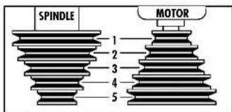
1: n_0 = 480 /
2: n_0 = 850 /
3: n_0=1.310/
4: n_0 = 2.120 /
5: n_0 = 3.010 /
MOTOR: n_0 = 1.400 /

natural_image
Simple line drawing of a rectangular prism with cross-hatching, labeled as Fig. 11 (no text or symbols on the diagram itself)Fig. 10

natural_image
Illustration of hands using a tool to adjust a mechanical component (no text or symbols present)

natural_image
Technical line drawing of a mechanical assembly with no visible text or symbols-
Never attempt to remount a faceplate turning to the faceplate for any reason. Never attempt to remount a between-centres turning if the original centres in the turning have been altered or removed. Be positive the lathe is set at the lowest speed if remounting a between-centres turning with non-altered original centres.
-
Use extra caution in mounting a between-centres or spindle turning to the faceplate, or a faceplate turning to between centres, for subsequent operation. Be positive the lathe is set at lowest speed for turning on.
-
Never mount a workpiece that contains any splits, cracks or knots to a faceplate or between-centres.
IMMEDIATELY SWITCH OFF THE MACHINE IN CASE OF:
-
Malfunction of the mainsplug, -socket or damaged cables.
-
Broken switch.
-
Smoke or smell caused by scorched insulation.
3. UNPACKING
(Fig. I.)
- H ead stock assembly. Includes: Head stock, drive spindle, motor, drive belt, pulleys (2), pulley guard, indexing head, 3/4" - 16 nut, no volt release switch, power cord, outboard spindle cover.
- Bed, (B1 = Head stock End, B2 = Foot End)
- Foot
- Bed clamping bolt
- T ail stock assembly
- Tool rest bracket
- Tool rest base assembly
- Centre assembly - tail stock
- Spur centre - head stock
- Tool rest - 300 mn
- Tool rest - 150 mm
Faceplates-110mm.(IN+OUT)

Never use gasoline or similar highly volatile solvents. Apply a coat of automobile wax to the bed. Wipe all parts thoroughly with a clean dry cloth.
4. ASSEMBLY AND INSTALLATION
I. MOUNTING HEAD STOCK TO BENCH
-
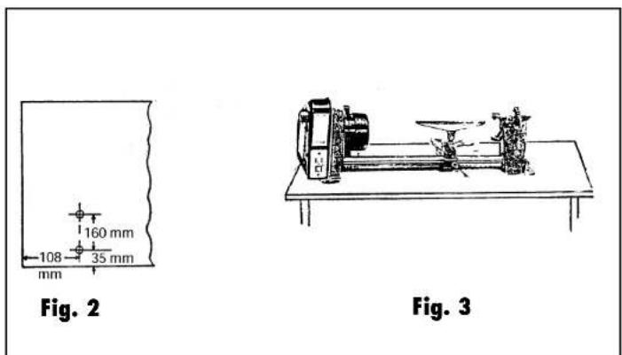
Drill two 10 mm holes in your bench or stand according to diagram, Fig.2. Note: Make sure that the top of your bench is positioned so that you don't drill into the legs or rail underneath.
-
Position the head stock assembly (A) on the bench and insert two 8 mm x 50 mm carriage bolts, through the two mounting holes in the base. Place a flat washer, a lock washer and a nut from the underside on each bolt. Tighten nuts only finger tight at this time.
-
ASSEMBLY OF LATHE BED HALVES (Fig.1)
-
Assemble the two bed halves together by inserting the connecting end (plugged end with threaded hole in the centre of the plug) of the head stock half (B1) into the machined inside diameter of the tail stock end (B2).
-
Insert the foot (E) into the open exposed end of the tail stock half (B2) and now insert the bed clamping bolt (F) through the foot (E) and on through the bed half (B2) and into the threaded hole in the connector end of the head stock bed half (B1). Start the threads of the bolt (F) into the threaded hole but do not tighten at this time.
-
Align the two keys (the strips of metal bar fastened to each bed half with screws) to be exactly in line. (This alignment is necessary so that the Tail Stock Assembly (G) and the Tool Rest Base Assembly (i) will slide freely over the joint formed by B1 and B2). To do this alignment, first align the two keys by "eye" as close as possible. Next using a metal straight edge against one side of the keys, slide the end of the straight edge across the joint first from one side of the joint and then from the opposite side. If there is a "click" or a hang-up of the straight edge at the joint, it will be obvious what relative direction the two halves of the bed will have to be rotated to achieve alignment. Repeat this process as many times on both sides of the keys as necessary to be satisfied that the alignment has been attained.
-
Without changing the relative position of the two halves (B1 and B2) tighten bolt (F) with a wrench. Recheck keyway alignment and if necessary readjust. Recheck halves of the bed (B1 and B2) can now be aligned by repeating step 2C as is necessary. Also, before retightening the foot (E) should be positioned so the keyway on the bed will be facing straight down when the foot is bolted to the bench.
-
Recheck key alignment and if necessary readjust per paragraph 2C above after loosening and tightening of the Bed Clamping Bolt Tighten the Bed Clamping Bolt (F) after each alignment attempt always keeping the Foot (E) parallel to key. Repeat above adjustment as many times as necessary until key alignment and squareness of the foot base (E) are obtained.
-
ASSEMBLY OF BED TO HEAD STOCK
-
Slide the tail stock assembly (G) and the tool rest base assembly (H) on to the bed as shown in Fig. 3.
-
Now insert this bed assembly into the head stock assembly (A), refer to Fig. 1, until the end of the tube is flush with the outboard end of the head stock boss located under the pulley cover.
-
Position the lathe on the bench so that the bed (B1 and B2) is parallel to the front edge of the bench.
-
Position the bed (B1 and B2) in the Head Stock Assembly so that the key(s) are directly under the centre of the bed towards the bench. Tighten the set screw in the Head Stock located on the motor side in line with the centre line of the bed.
-
Check to see if the foot (E) base is flat on the bench. If it is not, loosen bolt (F) several turns and reposition the foot (E) being very careful not to disturb the key alignment. Retighten bolt (F).
4. MOUNTING LATHE FOOT TO BENCH
-
After all steps in paragraph 3, above have been properly executed, mark the location of the two foot (E) mounting holes on the bench and drill two 10mm holes in the bench. Insert two 8mm × 50mm cariage bolts from the top into the mounting holes of the foot (E) and on through the drilled holes in the bench. Place a flat washer, a lock washer, then a nut on each of the bolts and then tighten securely with a wrench.
-
Now tighten the two nuts on head stock mounting bolts securely with a wrench.
5. ASSEMBLY OF SPUR CENTRE AND CUP CENTRE
I. Slide the carrier centre into the spindle of the main axle and the rotating centre into the loose head. Attention: do not hit the centres into the spindle or pinhole with a hammer, as this makes it difficult to remove them again later. Use a soft hammer or a piece of wood to knock them gently into place.
- With the blocking pin the main axle can be blocked in order to assemble clamping plates and centres. Pull the pin out slightly and turn it 90^ in order to block the main axle.
Never use it if the machine is running!
6. REMOVAL OF SPUR CENTRE FROM SPINDLE
To remove spur centre from spindle hold the spindle pulley with one hand. Using a wrench or pair of pliers, turn the hex key nut counterclockwise until centre is ejected.
7. REMOVAL OF CUP CENTREFROM RAM
To remove the cup centre from tail stock ram, insert 6 mm wood dowel or brass rod through the hole in the tail stock ram. Hold the centre with one hand and tap dowel or rod with a hammer. (Fig.5).
8. ADJUSTING TAIL STOCK TO BED
The tail stock supports the workpiece for spindle turning. To prevent excessive looseness or rocking it contains an adjustment-feature which bears against the keyway on the underside of the bed. To adjust refer to (Fig. 6) and proceed with the following:
With the tail stock loosened, tighten down the adjusting screw moderately against the keyway, then loosen about 1/4 turn.
With the tail stock still loosened, slide the tailstock along the full length of the bed. If it binds or sticks in anyone spot loosen the adjusting screw only enough so that the tail stock slides smoothly. If the tail stock feels loose and can be rocked slightly, tighten the screw only enough so that it will not bind when sliding the full length of the bed,
When both conditions have been met, tighten the lock nut.
9. ALIGNMENT OF TAIL STOCK CENTRE TO HEAD STOCK CENTRE
The spur centre and the cup centre are used for spindle turning and should always be in alignment. To align centres refer to Fig. 7 and adjust as follows:
Slide the tail stock toward the head stock so that the two points of the centres are very close but not touching. Tighten the tail stock lock. Loosen the bolt in the foot about two turns (do not drive the bolt forward with a blow because this will loosen the connector clamp and the alignment of the keyway will be lost). Using a 5 mm set screw wrench loosen the set screw on the back of the head stock which secures the bed. This screw is located about 45 mm. up from the bench. Swing the tail stock so that the two points are in line, then tighten the set screw in the head stock and the bolt in the end of the foot,
10. INSTALLATION OF BRASS SLUGS ON LOCKS
I. Brass slugs are required under the lock boLts of both the tail stock (G) and the tool rest base (I). The purpose of these brass slugs is to securely grip onto the bed Who, locked down without scarring the bed.
2. Locate the two (2) brass slugs in the box of parts.
3. Remove the lock bolt in each assembly. Refer to Fig. 8 (D) and (H) for locations.
4. Insert a brass slug in the threaded hole of each lock and then replace the lock bolts with wrench handles attached.
II. ASSEMBLY OF THE CARRIER PLATE AND THE SANDING ACCESSORY
Two carrier plates are supplied with the lathe, of which one (marked with "IN") is used for clamping workpieces in order to be able to rotate.
The other one (marked with "OUT") is attached to the main axle, on the left side of the machine. This carrier plate has a left thread and is used to clamp workpieces in order to be able to sand by hand. For this purpose the protective lid must be removed.
5. BASIC LATHE OPERATIONS
1. LATHE PARTS, CONTROLS AND FUNCTIONS (Fig. 8)
Recome familiar with the purpose of the various operating controls and parts of your lathe. Read and understand this manual before attempting to use the lathe.

Make sure that the power cord is removed from the supply before attempting to change the belt position.
2. CHANGING SPEEDS
The belt is shown positioned on the second steps from the outside end of the pulleys in Fig. 9. This causes the lathe to turn at 2.120 RPM. Refer to Fig. 10. Suppose you

natural_image
Illustration of a hand using a hammer to press or install a vise (no text or symbols present)
natural_image
Illustration of hands using a mechanical tool to adjust a mechanical component (no text or symbols visible)
natural_image
Mechanical assembly diagram showing a linkage mechanism with no visible text or symbols
natural_image
Mechanical assembly diagram showing a tool interacting with a mechanical component (no text or symbols visible)

wish to run the lathe slower, after referring to the speed chart (say 1.310 RPM), you must shift the belt inward.
- Raise the belt guard. To make the lathe go SLOWER shift belt inward. To make the lathe go FASTER shift belt outword.
- Rotate the motor pulley COUNTERCLOCKWISE with the left hand while pushing on the belt with your right hand.
- Continue to rotate the pulley while pushing on the belt until it "climbs" down into the next step of the motor pulley. Now rotate the spindle CLOCKWISE with your right hand while pushing on the belt with your left hand. The belt will climb up into the next step of the spindle pulley.
3. BELT TENSION ADJUSTMENT
Belt tension is provided by the weight of the motor pivoting the motor mounting bracket downward through the hinge of the hinge bracket. To decrease the belt tension, tighten the adjustment bolt located in the corner of the motor mounting bracket, thus restricting downward pivoting travel. Conversely, loosening the adjusting bolt allows increased pivot on the bracket thus increasing belt tension.
4. SPINDLE TURNING
If you have never done any amount of wood turning, we suggest that you practice using the various turning tools. Start with a small spindle turning.
Be sure to study the following pages of this manual. They explain and illustrate the correct use of the turning tools, the positioning of the tool rest and other information to help you gain experience.
- Select a piece of wood 300 x 50 x 50 mm.
- Draw diagonal lines on each end to locate the centres (Fig. 11).
- On one end, make a saw cut approximately 1.5 mm deep on each diagonal line. This is for the spur centre.
- The other end is the cup centre. Place the point of the cup center on the wood where the diagonal lines cross.
- Drive the cup centre into the wood. Use a wooden mallet or a plastic hammer, but put a piece of wood on the end of the cup centre to protect it. (Fig. 12).
- Remove the cup centre and drive the spur centre into the other end of the wood. Make sure the spurs are in the saw cuts. Remove the spur centre.
- Make sure the centres and the hole in the spindle and the tailstock ram are clean. Insert the spur centre into the headstock and the cup centre into the tail stock and tap them in lightly with a piece of wood. Do not drive them in.
- If the cup centre is not of the ball bearing type, put a drop of oil or wax on the wood where it contacts the cup centre. This wilt lubricate the wood while it is turning.
- Place the wood between the centres and lock the tail
stock.
- Move the cup centre into the wood by turning the hand wheel. Make sure that the cup centre and spur centre are 'seated' into the wood in the holes made in steps e and f above.
- Adjust the tool rest approximately 3 mm away from the corners of the wood and 3 mm above the centre line. (Fig. 13) Note the angled position of the tool rest base. Lock the tool rest base and the tool rest.
- Look at the speed chart. Notice that a 50 mm square turning up to 457 mm long should run at 850 R.P.M. for "roughing". Move the V-belt on the pulleys to the next to the slowest speed. Rotate the wood by hand to make sure that the corners do not strike the tool rest, and that the indexing pin is not engaged. (Fig. 14).
6. MAINTENANCE AND LUBRICATION

For your own safety, turn switch "off" and remove plug from power source outlet, before maintaining or lubricating your lathe.
A coat of automobile type wax applied to the bed will help to keep the surfaces clean and allow the tool rest and tail stock to move freely.
If the power cord is worn or cut, or damaged in any way, have it replaced immediately.
LUBRICATION
All of the ball bearings are packed with grease at the factory. They require no further lubrication. Periodically lubricate the ram in the tail stock with oil.
7. trouble shooting
- Motorwillnotrun.
Defective on/off switch or defective cable.
- Replace defective barts before using in the again.
Burn out motor.
- Any attempt to repair this motor may cause a hazard
unless repair is done by a qualified service technician.
- Lathe slows down when turning.
V-Belt too loose
- Adjust belt tension, see basic lathe operations.
- Tail stock rocks back and forth excessively.
Adjustingscrew too loose.
- Adjust screw, see assembly section.
- Head stock loose on bed.
Setscrew not to tight
- Tighten setscrew, see assembly section.
- Wood burns at tail stock end.
Cup centre too tight or not lubricated.
- Back off tail stack ram and lubricate cub centre. See ba-
sic lathe operations (spindle turning).
CE DECLARATION OF CONFORMITY (UK)
We declare under our sole responsibility that this
product is in conformity with the following standards or standardized documents
EN61029-
EN55014, EN61000-3-2, EN61000-3-3, EN55104
in accordance with the regulations:
89/392/EEC-91/368/EEC
93/44/EEC - 93/68/EEC
73/23EEC-89/336/EEC-92/31/EEC
from 26-05-1998
GENEMUIDEN NL
G.M. Ensing
Quality department

D Deutsch
93/44/E3C - 93/68/E3C
73/23E3C - 89/336/E3C - 92/31/E3C
от 26-05-1998
89/392/EEC - 91/368/EEC 93/44/EEC - 93/68/EEC
73/23EEC - 89/336/EEC - 92/31/EEC
ab 26-05-1998 GENEMUIDEN NL G.M. Ensing Quality department

93/44/EEC - 93/68/EEC
73/23EEC-89/336/EEC-92/31/EEC
vanaf 26-05-1998
GENEMUIDEN NL
G.M. Ensing
Quality department

CE KONFORMITETSERKLÆRING (DK)
Poupée mobile: No. I mors cône
Mesures totales: 1375 x 400 x 308 mm Poids: 38 kg
2. MESURES DE SECURITE SPECIALES
ALAMISE ENSERVICE DE LA MACHINE:
CEERKLÆRING AV ANSVARSFORHOLD (N)
89/392/EEC - 91/368/EEC 93/44/EEC - 93/68/EEC
73/23EEC - 89/336/EEC - 92/31/EEC
frà 26-05-1998
GENEMUIDEN NL
G.M. Ensing
Quality department

DK Dansk
6. VEDLIKEHOLD OG SM∅RING

CÉDÉCLARATION DE CONFORMITÉ (F)
93/44/EEC - 93/68/EEC
73/23EEC - 89/336/EEC - 92/31/EEC
26-05-1998
GENEMUIDEN NL
G.M. Ensing
Quality department


Produkt: Ferm tredreiebenk
TypeFHB-940,art.nr.460140
Ferm, Genemuiden, Overijssel, Nederland.
Løsthode: No. I morsekjegle
5. SORVAAMISEN ALKEET
I. OSAT, KÄYTTÖLAITTEET JA TOIMIN-NOT(KUVA8)
93/44/EEC - 93/68/EEC
73/23EEC - 89/336/EEC - 92/31/EEC
a partir de 26-05-1998
GENEMUIDEN NL
G.M. Ensing
Quality department


93/44/EEC - 93/68/EEC
73/23EEC - 89/336/EEC - 92/31/EEC
fràn 26-05-1998
GENEMUIDEN NL
G.M. Ensing
Quality department

- SERIAL NUMBER
- Serialnr.
- ORDER NUMBER/YEAR OF CONSTRUCTION
- LATHESPECIFICATIONS
- CAREFULLY READ THE INSTRUCTIONS BEFORE YOU USE THE WOOD LATHE!
- SPECIAL SAFETY RULES
- BEFORE USING THE MACHINE:
- ADDITIONAL SAFETY INSTRUCTIONS.
- IMMEDIATELY SWITCH OFF THE MACHINE IN CASE OF:
- UNPACKING
- ASSEMBLY AND INSTALLATION
- MOUNTING LATHE FOOT TO BENCH
- ASSEMBLY OF SPUR CENTRE AND CUP CENTRE
- Never use it if the machine is running!
- REMOVAL OF SPUR CENTRE FROM SPINDLE
- REMOVAL OF CUP CENTREFROM RAM
- ADJUSTING TAIL STOCK TO BED
- ALIGNMENT OF TAIL STOCK CENTRE TO HEAD STOCK CENTRE
- INSTALLATION OF BRASS SLUGS ON LOCKS
- ASSEMBLY OF THE CARRIER PLATE AND THE SANDING ACCESSORY
- BASIC LATHE OPERATIONS
- LATHE PARTS, CONTROLS AND FUNCTIONS (Fig. 8)
- CHANGING SPEEDS
- BELT TENSION ADJUSTMENT
- SPINDLE TURNING
- MAINTENANCE AND LUBRICATION
- LUBRICATION
- trouble shooting
- CE DECLARATION OF CONFORMITY (UK)
- EN61029-
- D Deutsch
- 93/44/E3C - 93/68/E3C
- 73/23E3C - 89/336/E3C - 92/31/E3C
- 73/23EEC - 89/336/EEC - 92/31/EEC
- CE KONFORMITETSERKLÆRING (DK)
- MESURES DE SECURITE SPECIALES
- CEERKLÆRING AV ANSVARSFORHOLD (N)
- DK Dansk
- VEDLIKEHOLD OG SM∅RING
- CÉDÉCLARATION DE CONFORMITÉ (F)
- 93/44/EEC - 93/68/EEC
- GENEMUIDEN NL
- Produkt: Ferm tredreiebenk
- TypeFHB-940,art.nr.460140
- SORVAAMISEN ALKEET
- OSAT, KÄYTTÖLAITTEET JA TOIMIN-NOT(KUVA8)
Brand : Ferm
Model : WLM1002
Category : Wood lathe