
SC 5232 - Air conditioner QLIMA - Free user manual and instructions
Find the device manual for free SC 5232 QLIMA in PDF.


| Product Type | Split System Air Conditioner (Wall-Mounted Indoor Unit + Outdoor Unit) |
| Model | SC 5232 |
| Brand | Qlima |
| Power Supply | 220-240 V~ / 50 Hz, Single Phase |
| Required Circuit Breaker | 16 A (slow-blow fuse or MCB) |
| Power Cord Size | 2.5 mm² (H07RN-F type for interconnecting cable) |
| Refrigerant | Fluorinated gas (F-gas compliant), possibly R32 or R290 |
| Refrigerant Piping Length (Max) | 4 m (pre-charged quick-connect pipes) |
| Indoor Unit Dimensions (Approx.) | 800 mm (W) x 280 mm (H) x 200 mm (D) |
| Outdoor Unit Dimensions (Approx.) | 700 mm (W) x 550 mm (H) x 250 mm (D) |
| Weight (Indoor Unit, Approx.) | 10 kg |
| Weight (Outdoor Unit, Approx.) | 25 kg |
| Operating Modes | Cooling, Heating, Dehumidification, Fan |
| Control | Remote Controller, Wireless Smart Kit (Wi-Fi optional) |
| Filter Type | Functional Filter (washable) |
| Drainage | Condensation drain hose (gravity drain) |
| Installation Requirements | Must be installed by certified personnel; follow local regulations |
| Safety Features | Earth leakage switch required; earthing mandatory; overheat protection |
| Warranty | 4 years (as per manual cover) |
| Accessories Included | Installation plate, anchors, screws, seal, drain joint, connecting pipe assembly, remote controller, wireless smart kit |
Frequently Asked Questions - SC 5232 QLIMA
User questions about SC 5232 QLIMA
0 question about this device. Answer the ones you know or ask your own.
Ask a new question about this device
Download the instructions for your Air conditioner in PDF format for free! Find your manual SC 5232 - QLIMA and take your electronic device back in hand. On this page are published all the documents necessary for the use of your device. SC 5232 by QLIMA.
USER MANUAL SC 5232 QLIMA
natural_image
Front view of a Qlima air conditioner unit with fan grille and ventilation grille (no visible text or symbols on the device itself)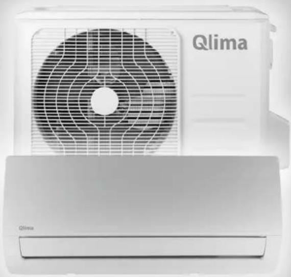
natural_image
Front view of a Qlima air conditioner unit with fan grille and ventilation grille (no visible text or symbols on the device itself)guarantee
4
YEARS
| DK | INSTALLATIONSMANUAL | 2 |
| FIN | ASENNUSOHJE | 24 |
| GB | INSTALLATION MANUAL | 46 |
| N | INSTALLASJONSMANUAL | 68 |
| PL | INSTRUKCJA MONTAŻU | 90 |
| S | INSTALLATIONSHANDBOK | 112 |
VIGTIG MEDDELELSE:
(1)

(2)
natural_image
Diagram of a mechanical assembly with directional arrows indicating motion or force (no text or symbols)natural_image
Technical line drawing of a mechanical component with internal threading and directional arrows (no text or symbols)6. MONTERING AF INSTALLATIONSPLADEN OG TILF∅RSEL AF R∅RLEDNING.
natural_image
Close-up of a mechanical assembly with metal rods and connectors, no visible text or symbolsnatural_image
Two black-and-white photos showing hands operating a mechanical device with labeled parts (no visible text or symbols)natural_image
Close-up of a hand holding a long cylindrical object in a lab or workshop setting (no visible text or symbols)natural_image
Interior view of a room with a wall-mounted device and a black-and-white photo showing a white object (no visible text or symbols)natural_image
Close-up of two electronic components with wires and connectors, one partially visible (no text or symbols)natural_image
Close-up of a mechanical tool with black and metallic components, no visible text or symbolsDK
natural_image
Close-up of a white and black object with a diagonal stripe, possibly a tool or device (no visible text or symbols)natural_image
Isometric line drawing of a device with a fan and internal components, showing a close-up of a small component (no text or symbols)natural_image
Two-panel black-and-white photo showing hands adjusting a metal pipe fitting with a valve, no visible text or symbols.natural_image
Close-up of hands holding a metallic pipe fitting with arrows indicating assembly or installation (no visible text or symbols)| Koblinsstørrelse(de sidste 2 delnumre) | Pund-kraft fod(1bf-ft) | Newtonmeter(N-m) | Kilogram-kraft meter(kgf-m) |
| -06 (9,5 mm) 18 - 20 | 24,4 - 27,1 2,4 - 2,7 | ||
| -08 (12,7 mm) 30 - 35 | 40,6 - 47,4 4,1 - 4,8 | ||
| -12 (19,1 mm) 45 - 50 | 61,0 - 67,7 6,2 - 6,9 | ||
| -16 (25,4 mm) 60 - 65 | 81,3 - 88,1 8,2 - 8,9 |
natural_image
Close-up of mechanical pipe fittings and fittings in three different angles (no text or symbols visible)natural_image
Close-up of mechanical components being held, showing assembly and mounting (no visible text or symbols)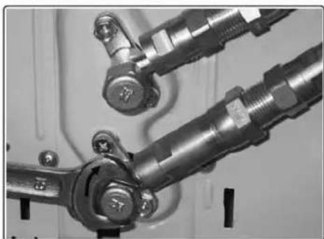
natural_image
Close-up of mechanical components with metallic fittings and bolts (no visible text or symbols)natural_image
Pure technical diagram showing two mechanical or structural components with no text, numbers, or symbols.Figur 15
Figur 19


natural_image
Two identical open electrical boxes with internal components, labeled 'X' (no text or symbols on the boxes themselves)(1)

(2)
natural_image
Diagram of a mechanical assembly with directional arrows indicating motion or force (no text or symbols)natural_image
Technical line drawing of a mechanical component with directional arrows indicating flow or movement (no text or symbols)6. ASENNUSLEVYN ASENNUS JA PUTKITUKSEN LÄPIVEDON TEKEMINEN
natural_image
Close-up of industrial machinery components with pipes and valves (no visible text or symbols)natural_image
Two black-and-white photos showing hands operating a pipe fitting with labeled components (no visible text or symbols)natural_image
Close-up of a hand holding a long cylindrical object in a kitchen setting (no visible text or symbols)natural_image
Interior view of a room with a wall-mounted device and a black strap (no visible text or symbols)natural_image
Close-up of electronic components including a metallic connector and black cable connectors (no visible text or symbols)natural_image
Close-up of a robotic gripper with black and white bands, resting on a plain surface (no text or symbols visible)natural_image
Close-up of a white aircraft wing with black stripes, mounted on a wooden post (no visible text or symbols)natural_image
Technical line drawing of a device with a fan and internal components, showing a close-up of a small component (no text or symbols present)natural_image
Two-panel image showing hands adjusting a pipe fitting with a valve, one being folded and the other holding a metallic connector (no text or symbols visible)natural_image
Close-up of hands adjusting a metallic pipe fitting inside a container (no visible text or symbols)natural_image
Close-up of two mechanical pipe fittings with numbered components and directional arrows (no text or symbols)| Liitännän koko(viimeiset 2 osanumeroa) | Jalkanaula(1bf-ft) | Newtonmetri(N-m) | Kilopondi(kgf-m) |
| -06 (halkaisija 9,5 mm) 18 | -20 24,4 - 27,1 2,4 - 2,7 | ||
| -08 (halkaisija 12,7 mm) 30 | -35 40,6 - 47,4 4,1 - 4,8 | ||
| -12 (halkaisija 19,1 mm) 45 | -50 61,0 - 67,7 6,2 - 6,9 | ||
| -16 (halkaisija 25,4 mm) 60 | -65 81,3 - 88,1 8,2 - 8,9 |
natural_image
Close-up of mechanical pipe fittings and fittings in a workshop setting (no visible text or symbols)natural_image
Close-up of mechanical components being held, showing assembly and mounting (no visible text or symbols)
natural_image
Close-up of mechanical components with metallic fittings and bolts (no visible text or symbols)natural_image
Pure technical line drawing of two mechanical or electrical components with no text, numbers, or symbolsKuva 15
Kuva 19

natural_image
Two identical views of an open industrial machine casing with internal components, labeled 'X' (no text or symbols on the casing itself)Install this device only when it complies with local/national legislation, ordinances and standards. This product is intended to be used as an air conditioner in residential houses and is only suitable for use in dry locations, in normal household conditions, indoors in living room, kitchen and garage. Check the mains voltage and frequency. This unit is only suitable for earthed sockets, connection voltage 220-240 V\~ / 50 Hz. Model SC42xx, SC52xx & SCJAxx19 has to be connected directly to the supply source.
This installation manual is intended for use by individuals possessing adequate backgrounds of electrical, electronic, refrigerant and mechanical experience. Any attempt to install or repair the appliance may result in personal injury and property damage. The manufacturer or seller cannot be responsible for the interpretation of this information, nor can it assume any liability in connection with its use.
The information, specifications and parameter are subject to change due to technical modifications or improvement without any prior notice. The accurate specifications are presented on the nameplate label.
- Please read this installation manual completely before installing the product.
- When the power cord is damaged, replacement work shall be performed by authorized personnel only.
- Installation work must be performed in accordance with all European, national and / or local directives and standards and must be done by authorized personnel only. The guarantee is invalid for damage caused by neglect or by actions that deviate from those in this instruction booklet.
- Always make sure to wear the correct personal safety protections such as protective eyewear, gloves, mouthcaps, ear protection etc.
Internet:
For your convenience you can download the latest version of the user-, installation- and/or service manual on www.qlima.com

WARNING!
DO NOT INSTALL UNLESS YOU ARE CERTIFIED:
- This tube-set contains fluorinated gasses covered by the European F-gas Regulation and may therefore only be handled by qualified installers. The warranty will be void if any unauthorized installations, service, repairs or modifications are made to the installation.
- This wall mounted split air conditioner unit contains fluorinated gasses covered by the European F-gas regulation and may therefore only be actuated by qualified installers; the placement and fixing of this units is not covered by this regulation and may therefore be performed by any capable person.
Do not remove and/or reinstall the unit by yourself if you do not have the adequate electrical, electronic, refrigerant, mechanical experience and authorisation.
- Improper installation can cause water leakage, electrical shock, refrigerant leakage or fire. Please consult authorized dealer or specialized air conditioner engineer for the installation work. Please note faults caused by improper installation is not covered by warranty.
- Unit must be installed in an easily accessible area. Any additional cost required to hire special equipment to service the unit will be the responsibility of the customer
CONTENT
- Safety precautions
- Items packed with the unit
2.1 items packed with the unit (for SC42xx & SC52xx & SCJAxx19 models) - Activities for installing the air conditioner for the SC42xx & SC52xx & SCJAxx19 models.
- Determining the location of the inside and outside unit.
- Possibilities for installing the piping from the interior unit to The exterior unit.
- Mounting the installation plate and making the piping feedthrough.
6.1 Mounting the installation plate of the interior unit.
6.2 Drilling the piping, condensation hose and cable feed-through.
- Connection the coolant pipes.
7.1 Connecting and disconnecting the coolant pipes for the SC42xx & SC52xx & SCJAxx19 models.
- Connection the condensation drainage hose.
8.1 Connection the condensation drainage hose to the interior unit.
8.2 Drain joint installation.
-
Electrical work.
-
Connecting the electrical cables.
10.1 Connecting the electrical cables to exterior unit.
10.2 The wire connection between indoor unit and outdoor unit.
10.3 Connecting the electrical cables for the interior unit.
-
Checking the cooling system for leakage
-
Test running after installation.
1. SAFETY PRECAUTIONS
The following should be always observed for safety:
- Be sure to read the following WARNING before installing the airconditioner.
- Be sure to observe the cautions specified here as they include important items related to safety.
- After reading this instructions, be sure to keep it together with the owners manual in a handy place for future reference.
The air conditioner contains a refrigerant and can be classified as pressurized equipment. Therefore always contact an authorized air conditioning engineer for installation and maintenance of the air conditioner. The air conditioner must be inspected and serviced on an annual base by an authorized air conditioning engineer.
The specifications of the fuse are printed on the circuit board, such as :
T3.15AL/250VAC, T5AL/250VAC, T3.15A/250VAC, T5A/250VAC, T20A/250VAC, T30A/250VAC, etc.
NOTE: For the units with R32 or R290 refrigerant, only the blast-proof ceramic fuse can be used.

WARNING
Do not install it yourself.
- Incorrect installation could cause injury due to fire, electric shock, the unit falling or leakage of water. Consult your dealer from whom you purchased the unit or an authorised installer.
Install the unit securely in a place which can bear the weight of the unit.
- When installed in an insufficiently strong place, the unit could fall causing injury.
Use the specified electrical wires to connect the indoor and outdoor units securely and attach the wires firmly to the terminal board connecting sections so the stress of the wires is not applied to the sections.
- Incorrect connection and fixing could cause a fire.
Be sure to use the provided or specified parts for the installation work.
- The use of defective parts could cause an injury due to a fire, electric shock, the unit falling, etc.
Perform the installation securely referring to the installation instruction.
- Incorrect installation could cause a personnel injury due to fire, electric shock, the unit falling or leakage of water.
Perform electrical work according to the installation manual and be sure to use an exclusive circuit.
- If the capacity of the power circuit is insufficient or there is incomplete electrical work, it could result in a fire or an electric shock.
Check that the refrigerant gas does not leak during installation or after installation is completed.
- Leaking refrigerant is bad for the environment and could cause global warming.
Attach the electrical part cover to the indoor unit and the service panel to the outdoor unit securely.
- If the electrical part covers off the indoor unit and/or the service panel of the outdoor unit are not attached securely, it could result in a fire or electrical shock due to dust, water, etc.
GB

CAUTIONS
- This equipment must be earthed. It can possibly cause electrical shock if grounding is not perfect. Do not use an extension cable. Otherwise it can cause electric fire or shock.
- The mains supply in the house must be equipped with an earth leak switch. If it is not equipped with an earth leak switch this could result in electrical shocks and fire.
Perform the drainage/piping work according to the installation instruction.
- If there is a defect in the drainage/piping work, water could leak from the unit and household goods could get wet and be damaged.
2. ITEMS PACKED WITH THE UNIT
2.1 ITEMS PACKED WITH THE UNIT (for SC42xx & SC52xx & SCJAxx19 models)
| Number Name of Accessories Quantity | ||
| 1 Installation plate 1 | ||
| 2 Clip Anchor 5 | ||
| 3 Self-tapping screw ‘A’ ST 3.9x25 5 | ||
| 4 Seal 1 | ||
| 5 Drain joint 1 | ||
| 6 Connecting pipe assembly 1 | ||
| 7 Remote controller | 1 | |
| 8 Self-tapping screw ‘B’ ST 2.9x10 | 2 | |
| 9 Remote controller holder | 1 | |
| 10 | Wireless smart kit | 1 |

NOTE!
Except the above provided parts, the other parts needed during installation are to be purchased separately by the buyer of the air conditioner.
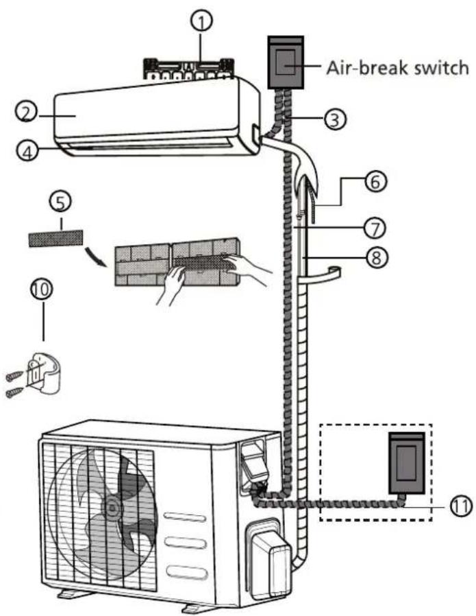
(1)

(2)
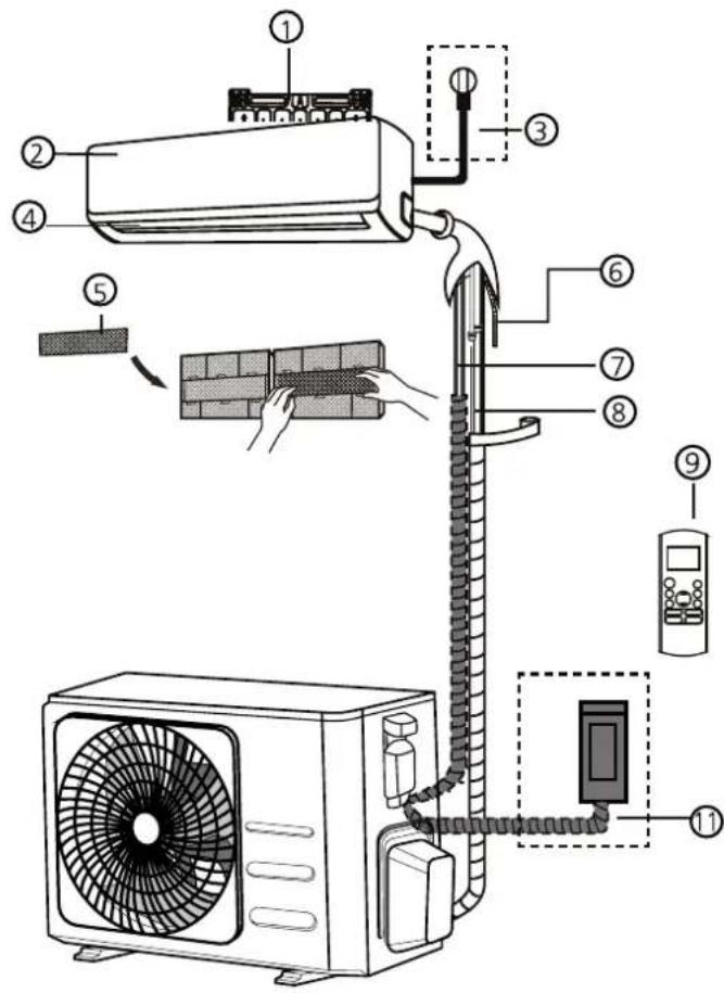
① Wall mounting plate
② Front panel
③ Power cable
④ Louver
⑤ Functional filter
⑥ Drainage pipe
⑦ Signal cable
⑧ Refrigerant piping
⑨ Remote controller
⑩ Remote controller holder
⑪ Outdoor unit power cable

ATTENTION
This illustration is for explanation and indication purposes only. The illustration may be different from the air conditioner you purchased.
3. ACTIVITIES FOR INSTALLING THE AIR CONDITIONER
a. Decide where to position the indoor and outdoor unit. See chapter 5 and 6.

CAUTION
- Keep in mind where the condensation can be drained off to.
- The distance between indoor and outdoor unit can be max. 4 m (the length of the piping).
b. Fit the Installation Plate for the indoor unit. See chapter 7.1
c. Drill a hole to outside that the piping can be fed through. See chapter 7.2.
Bending the refrigerant piping at the back of the unit needs to be done with the highest care! The piping consists of copper. When bending the highlighted part more than 1 time the Copper will start cracking due to a physical process. Cracking can cause leakage refrigerant leakage and is not covered by the warranty.

natural_image
Diagram of a mechanical assembly with directional arrows indicating motion or force (no text or symbols)e. Feed the condensation hose through the hole in the wall and connect it to the hose which is installed on the interior unit. See chapter 9.1.

TIP
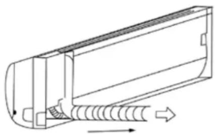
The condensation hose can be more easily attached by pulling the bottom of the interior unit about 5 cm from the wall and putting something temporarily between it and the wall so that the gap remains open. See figure 3.
f. Now click the bottom hooks to of the interior unit to the mounting plate.
g. Position the exterior unit see chapter 5.2
h. Connect the quick connector coupling with the coupling on the exterior unit. Then connect the power cable with the earth wire to the interior and exterior unit. See chapter 8.
i. Check the air conditioner for any cooler liquid leakage. See chapter 13.
j. Check that the air conditioner is properly installed.
k. Connect the plug of the power supply cable to the power supply and check that the air conditioner is working properly. See chapter 11.1.
4. DETERMINING THE LOCATION OF THE INSIDE AND OUTSIDE UNIT.
4.1 Determining the location of the inside unit.
- Do not expose the indoor unit to heat or steam.
- Select a place where there are no obstacles in front or around the unit.
- Make sure that condensation drainage can be conveniently routed away continuously going downwards.
- Do not install near a doorway.
- Ensure that the space on the left and right of the unit is more than 12cm.
- Use a wire detector to detect wires and/or electric cables. to locate studs to prevent unnecessary damage to the wall.
- The top of the indoor unit should be installed on the wall at a height of 2.3 metres or more from the floor.
- The indoor unit should be installed allowing a minimum clearance of 15cm from the ceiling.
- Be sure to level the indoor unit.
- When determining the location of the interior unit take the possible locations of the exterior unit into account. Interior and exterior part must be linked by piping and cables.

4.2 Determining the location of the exterior unit.
• Install the outdoor unit on a rigid base to prevent increasing noise level and vibration.

NOTE
The outdoor unit produces sound when in use, this could interfere with local legislation. It is the responsibility of the user to check and to make sure the equipment is in full compliance with local legislation.
- Determine the air outlet direction where the drainaged air is not blocked.
• Take the air conditioner weight into account. - If an awning is built over the outdoor unit to prevent direct sunlight or rain exposure, make sure that heat radiation from the condenser is not restricted.
- Ensure that the clearance around the back of the unit is more than 30 cm and left side is more than 30 cm. The front of the unit should have more than 200 cm of clearance and the connection side (right side) should have more than 60 cm of clearance. See picture 5.
- Be sure to level the outdoor unit
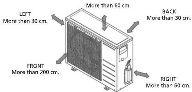
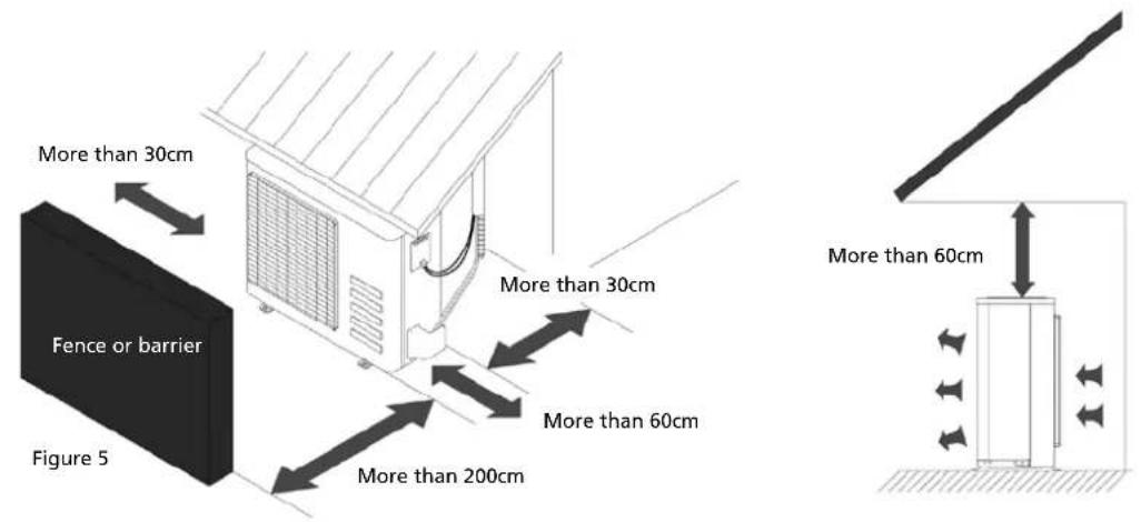
- When determining the location of the exterior unit take into account the possible location of the interior unit. The interior and exterior units must be connected by pipes and cables.
- Do not place animals and plants or other obstacles in the path of the air inlet or outlet.
• Always install the air conditioner at an easily accessible location. - Consult and follow local legislation regarding mounting and installation of air conditioner equipment.
- In the case that the installation place is exposed to strong wind such as a seaside, make sure the fan is operating properly by putting the unit lengthwise along the wall or using a dust or shield plates. See picture 6.

Figure 6

- If the exterior unit is installed on a roofing structure or exterior wall then it can result in bothersome noise and vibrations.
- Ensure that the exterior unit can be attached to a stable substructure.

ATTENTION
If need suspending installation, the installation bracket should accord with all technical requirements. The installation wall should be strong enough or actions to reinforce should be taken. The connection between bracket and wall, bracket and the air conditioner should be firm, stable and reliable. In case of any doubts or uncertainty do not attempt to install the unit but have the support calculated and engineered by a skilled engineer.
5. POSSIBILITIES FOR INSTALLING THE PIPING FROM THE INTERIOR UNIT TO THE EXTERIOR UNIT.

NOTE ON PIPING ANGLE
Refrigerant piping can exit the indoor unit from Left-rear side (when you're facing the back of the unit)
natural_image
Technical line drawing of a mechanical component with internal spring and directional arrows (no text or symbols)6. MOUNTING THE INSTALLATION PLATE AND MAKING THE PIPING FEEDTHROUGH.
6.1 Mounting the installation plate of the interior unit.

WARNING!
Use a pipe detector to detect electrical conduits and pipes in the wall before drilling the required holes to prevent unnecessary damage to the wall or dangerous situations.
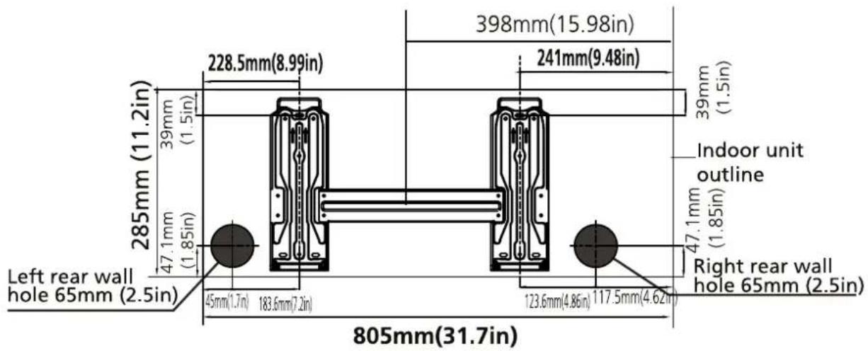
a. Fit the installation plate ① horizontally on structural parts of the wall with spaces around the installation plate. See figure 8.
b. If the wall is made of brick, concrete or the like, drill eight (8) 5mm diameter holes in the wall. Insert clip anchor ② for appropriate mounting screws ③.
c. Fit the installation plate ① on the wall with eight (8) type "A" screws ③.
REMARK
Mount the mounting plate and drill the holes in the wall corresponding to the material of the wall and the mounting points on the mounting plate in question (dimensions are in "mm" unless otherwise indicated).
Figure 8
Correct orientation of Installation Plate
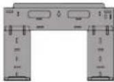


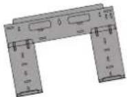

SC 4225 / SC 5225 / SCJA 2519 / SC 4232 / SC 5232
SC 4248 / SC 5248 / SCJA 4819

6.2 Drilling the piping, condensation hose and cable feed-through.
a. Determine the positions of the holes according to the diagram detailed in Fig. 9. Drill one (1) hole slanting slightly downwards to outdoor side, this will prevent water to come indoors (fig 10).
b. Always use wall hole conduit when drilling metal grid, metal plate or the like.

Figure 10
7. CONNECTING THE COOLANT PIPES
7.1 Connecting and disconnecting the coolant pipes
TOOLS NEEDED
- You will require the following tools to carry out this installation work correctly:
1x open-ended spanner, 19 mm
1x open-ended spanner, 22 mm/24mm
1x open-ended spanner, 24 mm/27mm
1x Allen key, 5 mm
1x Philips screwdriver
1x leak detection spray or alternatively soap suds (water/detergent mix)
IMPORTANT INFORMATION
- Follow the detailed instructions for connecting the refrigerant pipes to the indoor unit and outdoor unit. We can only provide a warranty if the lines are installed correctly as described in the instructions.
- Do not remove the sealing caps and stoppers until immediately before you install the lines.
- To prevent leaks, ensure that the quickrelease screw connections are absolutely free of dirt. Moisture or foreign bodies will adversely affect the function of the quickrelease connectors, leading to a risk of refrigerant loss (not covered by the warranty).
- Only install refrigerant lines outdoors in dry weather.
- The refrigerant lines must not be installed and then plastered over.
- Please make sure that refrigerant is never allowed to enter the environment. Improper handling of refrigerant may be harmful to health. Always wear work gloves and goggles when handling refrigerant.
- Do not smoke during the installation work. The equipment must never be operated without the refrigerant lines connected, otherwise the equipment will be damaged immediately.
- The screw connections may only be tightened using the appropriate open-ended spanner.


NOTE
To distinguish the connectors to be connected to the indoor unit and outdoor unit, the connectors of the refrigerant pipe has been labelled "A", "B", "C" and "D". Ensure the marks on the connectors are the same to the indoor's and outdoor's respectively during connection.
- Remember that if they are tightened with too little torque, they will leak, but if they are tightened with too much torque, the screw connections may suffer damage. If you should not be confident about connecting the refrigerant line connectors yourself, it is imperative that you contact your customer service team or a refrigeration contractor.
Important! The EQ valves are only designed for one-time installation. Their seal can not be guaranteed if they are installed on more than one occasion. This will also void the warranty.
CONNECTING THE REFRIGERANT PIPES TO INDOOR UNIT
- Do not remove the plastic seals from the indoor equipment and the appropriate refrigerant pipe until immediately before you connect them.
- Align the refrigerant pipes correctly, make sure the dimensions of the connecting refrigerant pipe are the same. Place the screw connector on the refrigerant pipes just on to the thread on the indoor equipment and tighten the first few threads by hand.
IMPORTANT: Before you continue, it is essential that you read the following instructions carefully.

natural_image
Close-up of a hand holding a flexible hose with wires, next to a metal enclosure (no visible text or symbols)- Hold the points marked ① using an open-ended spanner and turn the nuts only at the points marked ② using an open-ended spanner (Select the appropriate spanner according to the dimensions of the connector).

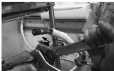
natural_image
Person operating a mechanical device with hoses and a pipe (no visible text or symbols)- Ensure that the screw connectors do not skew as you tighten them and work quickly.
IMPORTANT: Since the coupling works with tapping rings, it may leak if you undo and reconnect the pipes. This will also void the warranty.
- After finishing the connection, use the tape to wrap the refrigerant pipe and connecting cable together.

natural_image
Close-up of a hand holding a long cylindrical object in a kitchen setting (no visible text or symbols)- After finishing connecting the couple of the quick connectors, pass drain hose and refrigerant pipes through the wall hole.
NOTE : The quick connector parts must be placed outside of room. Using wall hole sleeve, cap and neoprene to seal the wall hole.

natural_image
Interior view of a room with a wall-mounted appliance and a black-and-white striped component (no visible text or symbols)- In order to prevent the quick connector parts from being exposed in the air, the sound deadening pads are supposed to be used during the installation.

natural_image
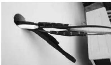
Close-up of two metallic cables with exposed wires and a damaged panel (no text or symbols visible)- Wrap up the quick connectors with the sound deadening pads, pack down the pads solid as tightly.
natural_image
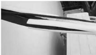
Close-up of a black plastic tool with attached black components, lying on a plain surface (no text or symbols visible)- Then wrap up the connectors with the black insulation material, for the top exposed part, use the white insulation material (supplied in Accessories box) to wrap it up completely.
natural_image
Close-up of a white and black elongated object with a dark horizontal stripe, possibly part of a mechanical or architectural component (no visible text or symbols)- At last, use the tape to wrap the refrigerant pipe and connecting cable together.
NOTE ON PIPING ANGLE
Refrigerant piping can exit the indoor unit from Left-rear side (when you're facing the back of the unit)
CAUTION
Be extremely careful not to dent or damage the piping while bending them away from the unit. Any dents in the piping will affect the unit's performance.
REFRIGERANT PIPING CONNECTION
Connecting the refrigerant pipe to outdoor unit
CAUTION: For your safety, always wear goggles and work gloves when connecting the pipes.
NOTE: To distinguish the connectors to be connected to the indoor unit and outdoor unit, the connectors of the refrigerant pipe has been labelled "A", "B", "C" and "D". Ensure the marks on the connector are the same to the indoor's and outdoor's respectively during connection.
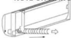
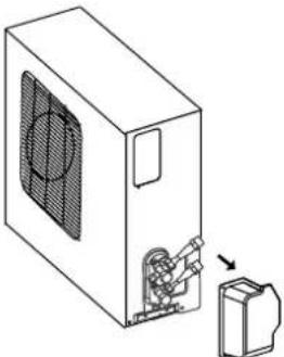
- First remove the water tray on the outdoor unit.
natural_image
Technical line drawing of a device with fan and internal components, showing a close-up of a component (no text or symbols)- Do not remove the plastic seals from the outdoor unit and the appropriate refrigerant pipes until immediately before you connect them.
natural_image
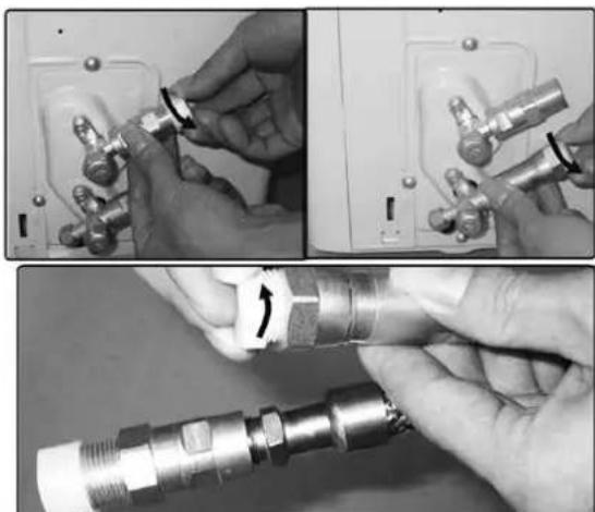
Two-panel image showing hands installing a pipe fitting component, one with a black clip and the other with a metallic connector (no text or symbols visible)- Align the refrigerant pipes correctly so that they line up with the valves and are not stressed. Place the screw connector on the refrigerant line just on to the thread on the outdoor unit and tighten the first few threads by hand.
NOTE: The refrigerant pipes must be connected to the valves on the outdoor unit with as little stress as possible.
IMPORTANT: Before you continue, it is essential that you read the following instructions carefully.

natural_image
Close-up of hands holding a metallic pipe fitting with arrows indicating assembly or adjustment (no visible text or symbols)- Now tighten the bottom screw connector first and then the top screw connector using the open-ended spanner. Hold the points marked ① using an open-ended spanner and turn the nuts only at the points marked ② using an open-ended spanner (Select the appropriate spanner according to the dimensions of the connector).
- Ensure that the screw connectors do not skew as you tighten them and work quickly. See the next page for the proper torque.
IMPORTANT: Since the coupling works with tapping rings, it may leak if you undo and reconnect the pipes. This will also void the warranty.

natural_image
Close-up of two mechanical pipe fittings with numbered components and directional arrows (no text or symbols)| Coupling size(last 2 part numbers) | Pound-force foot(1bf-ft) | Newton meter(N-m) | Kilogram-force meter(kgf-m) |
| -06 (9.5mm dash size) 18 | -20 24.4 - 27.1 2.4 - 2.7 | ||
| -08 (12.7mm dash size) 30 | -35 40.6 - 47.4 4.1 - 4.8 | ||
| -12 (19.1mm dash size) 45 | -50 61.0 - 67.7 6.2 - 6.9 | ||
| -16 (25.4mm dash size) 60 | -65 81.3 - 88.1 8.2 - 8.9 |
After completing steps 1-4, check that all the connections are sealed correctly using leak detection spray or soap suds. If any bubbles form, the system has a leak and the screw connectors must be retightened using an open-ended spanner.
- Now remove the cover on the top valve using a 19 mm open-ended spanner. Open the valve by turning it counter-clockwise as far as it will go using a 5 mm Allen key. The valve is now open. If the valve is not opened fully, the system may malfunction and suffer damage. Screw the cover back on to the top valve and tighten it well to ensure that it is properly sealed.

natural_image
Close-up of mechanical pipe fittings and fittings in a workshop (no visible text or symbols)
natural_image
Close-up of mechanical components with no visible text or symbols- Now remove the cover on the bottom valve using a 19 mm open-ended spanner. Open the valve by turning it counter-clockwise as far as it will go using a 5 mm Allen key. The valve is now open. If the valve is not opened fully, the system may malfunction and suffer damage. Screw the cover back on to the bottom valve and tighten it well to ensure that it is properly sealed.

natural_image
Close-up of mechanical components being adjusted, showing pipe fittings and joints (no visible text or symbols)
natural_image
Close-up of mechanical components with no visible text or symbolsImportant! The conical ring on the valve has an important sealing function together with the sealing seat in the caps. Ensure that you do not damage the cone and that you keep the cap free of dirt and dust.
-
After completing steps 1-6, check that all the connections are sealed correctly using leak detection spray or soap suds. If any bubbles form, the system has a leak and the screw connectors must be retightened using an open-ended spanner.
-
Start the equipment so that the operating pressures build up inside it. Check all the connectors again for signs of leaks
a) during cooling mode
b) in heating mode.
If any bubbles form, the system has a leak and the screw connectors must be retightened using an open-ended spanner.
8. CONNECTION THE CONDENSATION DRAINAGE HOSE
8.1 Connection the condensation discharge hose to the interior unit.
Connect the included condensation drainage hose to the interior unit by sliding the hose over the hose nipple on the interior unit. Ensure that the condensation drainage hose always runs downwards and do not hang the end in the water. See fig. 15.
Always run the condensation drainage hose under the coolant pipes to prevent that the condensation tray from overflowing.

CAUTION
- Be sure that the drain hose is located at the lowest side of the bundle. Locating at the upper side can cause drain pan to overflow inside the unit.
- Run the drain hose sloped downward over the whole length to drain out the condensed water smoothly.

natural_image
Pure electrical circuit lines without any symbolsDo not block water flow by a rise.

Do not put the end of drain hose into water.
Figure 15
8.2 Drain joint installation
Fit the seal into the drain elbow, then insert the drain joint into the base pan hole in the bottom of the outdoor unit, rotate 90^ to assemble them securely. Connect the drain joint with an extension drain hose (not included). In this way condensed water, which is produced during heating mode of the air conditioner, can be drained away. See fig. 16.

Figure 16
9. ELECTRICAL WORK
- Connect the air conditioner to a separate group. Ensure that this group has the correct fuse
• See following table. - Power voltage supplied should be in the range of 95%\~105% of rated voltage on rating table.
- The power supply must have an earth leak switch installed.
- Ensure the air conditioner is grounded well.
- Connect the wires according the attached electrical connection diagram located on the panel of the outdoor unit. See chapter 11
- All wiring must comply with local and national electrical standards and codes and be installed by qualified and skilled people.
| Model Power supply | Input Rated Current (Switch/Fuse) | Power cord size |
| ≤ 3,5 kW 230V 50 Hz 16A 2,5 mm | ^2 | |
| >3,5 kW 230V 50 Hz 16A slow 2,5 mm | ^2 |

NOTE!
The supply voltage should be consistent with the rated voltage of the air conditioner.
10. CONNECTING THE ELECTRICAL CABLES.
10.1 Connecting the electrical cables to exterior unit.
a. 4,5 Meter cable for electrical connection between indoor and outdoor unit is delivered with the package and is included in the refrigerant piping sleeve (indoor unit).
B. The electrical cable is provided with an electrical quick connector.
c. The outdoor unit is also provided with electrical quick connector.
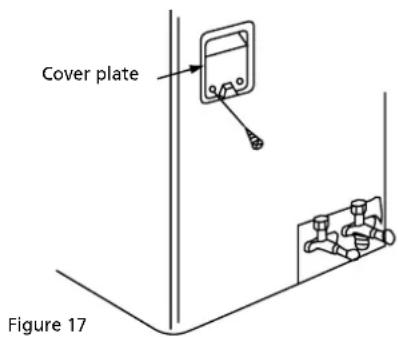
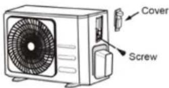
d. Remove the control cover from the outdoor unit by loosening the screw.
e. Click the connector of the interior unit into the connector of the exterior unit and secure the cable to the terminal block with the cable clamp mounted on it.
f. The earth cable must be connected directly to the metal plate on which the terminal strip is mounted. The location is indicated with the symbol
g. Only connect the power supply cable once the entire installation of the air conditioner has been completed.

TAKE CARE
For models with a capacity < 4.5 kW plug the plug into a wall socket.
For models with a capacity > 4.5 kW connect the power supply cable directly the power source.
Do not use a plug and socket as the high current can damage both the terminals of the plug and the socket and even cause a fire.
10.2 The wire connection between indoor unit and outdoor unit.
Align the two connectors and insert into each other until they are fixed with a clicking sound. The Y/G wire should be connected individually. Secure the cable onto the control board with cord clamp.

a. Insulate unused wires with PVC electrical tape. Arrange them so that they do not touch any electrical or metal parts.
b. Replace the wire cover on the side of the unit, and screw it in place.
NOTE: If the cable clamp looks like the following, please select the appropriate through-hole according to the diameter of the wire.

When the cable is not fasten enough, use the buckle to prop it up, so it can be clamped tightly.
10.3 Connecting the electrical cables for the interior unit.
a. Connect the cable to the indoor unit
b. Indoor/Outdoor connection cable should be H07RN-F type, 2,5 mm².
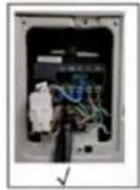
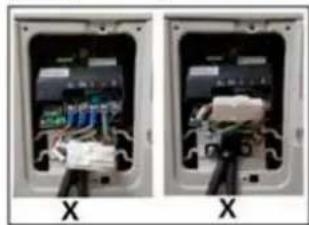
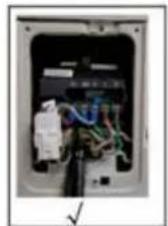
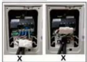
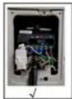
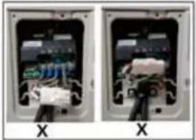
c. To mount the cable to the interior unit: Open the front panel and the cover plate of the terminal strip on the right hand side of the interior unit. Figure 19.
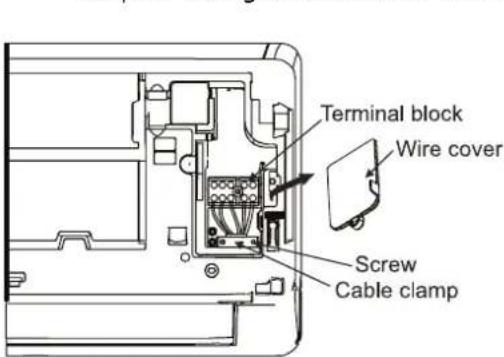
Figure 19

natural_image
Two views of an open electrical switch or socket with visible internal components and wiring (no text or symbols)d. The cable can be fed through from the back of the interior unit to the terminal strip.
e. Connect the electrical wires to the terminal strip, for the correct location.
TAKE CARE
For models with a capacity < 4.5 kW plug the plug into a wall socket.
For models with a capacity > 4.5 kW connect the power supply cable directly the power source.
Do not use a plug and socket as the high current can damage both the terminals of the plug and the socket and even cause a fire.
11. CHECK FOR COOLANT LEAKAGE

TAKE CARE
Evacuating the coolant piping and the interior unit of the air conditioner must be carried out in accordance with the applicable national regulations. The test for coolant leakage of the coolant piping and the interior unit may only be carried out by a certified fitter.
POSSIBILITIES FOR LEAK CHECK AIR CONDITIONER
- Soap water method: Apply a soap water or a liquid neutral detergent on the indoor unit connection or outdoor unit connections by a soft brush to check for leakage of the connecting points of the piping. If bubbles come out, the pipes have leakage.
• Dedicated special leak detector: Use the leak detector to check for leakage.
12. TEST RUNNING AFTER INSTALLATION
Perform test running after completing electrical safety check and gas leak check.
The test running time should last more than 30 minutes.
Check if all the functions works well during test running. Especially check whether the drainage of indoor unit is smooth or not.
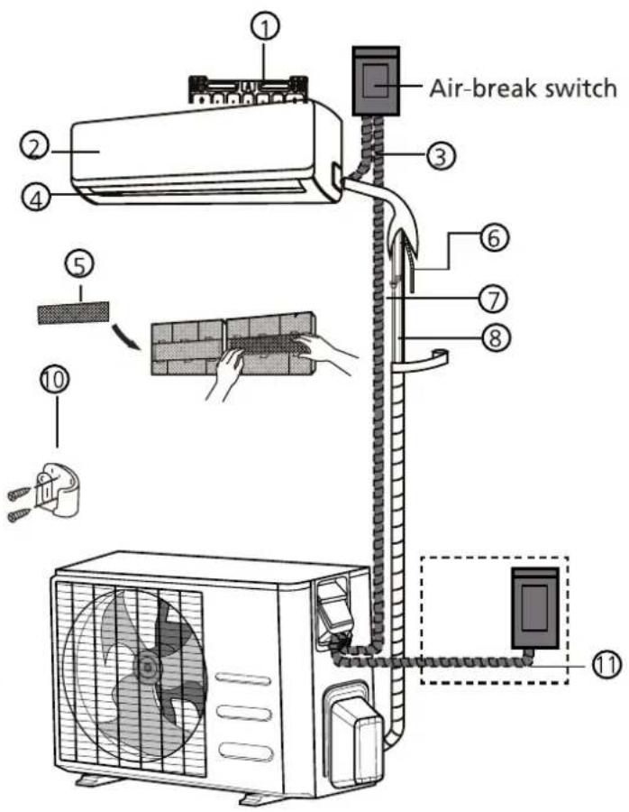
VIKTIG INFORMASJON:
(1)

(2)
① Veggmonteringsplate
② Frontpanel
③ Strømledning
④ Spjeld
⑤ Funksjonsfilter
⑥ Dreneringsrør
⑦ Signalkabel
⑧ Kjølemiddelrør
⑨ Fjernkontroll
⑩ Fjernkontrollholder
⑪ Utedelens strømkabel

OBS
natural_image
Pure electrical circuit lines without any symbolse. Før kondenseringsslangen gjennom hullet i veggen og koble den til slangen som er installert på innedelen. Se kapittel 9.1.
TIPS
natural_image
Technical line drawing of a mechanical component with directional arrows indicating flow or movement (no text or symbols)6. MONTERINGSPLATEN MONTERES OG R∅RLEDNINGEN GJENNOMF∅RES.
7. KOBLE TIL KJ∅LEMIDDELR∅RENE.
KOBLING AV KJ∅LEMIDDELR∅RENE TIL INNEDELEN
natural_image
Industrial equipment setup with pipes and valves in a factory setting (no visible text or symbols)natural_image
Two-panel black-and-white photo showing hands operating a pipe fixture with labeled components (no visible text or symbols)natural_image
Close-up of a long, curved object mounted on a metal frame in a workshop setting (no visible text or symbols)natural_image
Interior view of a room with a wall-mounted appliance and a black-and-white striped component (no visible text or symbols)natural_image
Close-up of two metallic cables with exposed wires and a damaged panel (no text or symbols visible)natural_image
Close-up of a black plastic tool with attached black components, resting on a white surface (no text or symbols visible)natural_image
Close-up of a white and black elongated object with a dark horizontal stripe, possibly part of a mechanical or architectural component (no visible text or symbols)natural_image
Technical line drawing of a device with fan and internal components, showing a close-up of a component (no text or symbols)natural_image
Two-panel image showing hands installing a pipe fitting component, one with a black clip and the other with a metallic connector (no text or symbols visible)natural_image
Close-up of hands adjusting a metallic pipe fitting with a tool, shown in two sequential views (no text or symbols visible)| Koblingsstørrelse(siste 2 delenumre) | Pund-kraft fot(1bf-ft) | Newtonmeter(N-m) | Kilogram-kraftmåler(kgf-m) |
| -06 (9,5mm dash størrelse) | 18 - 20 24,4 - 27,1 | 2,4 - 2,7 | |
| -08 (12,7mm dash størrelse) | 30 - 35 40,6 - 47,4 | 4,1 - 4,8 | |
| -12 (19,1mm dash størrelse) | 45 - 50 61,0 - 67,7 | 6,2 - 6,9 | |
| -16 (25,4mm dash størrelse) | 60 - 65 81,3 - 88,1 | 8,2 - 8,9 |
natural_image
Mechanical assembly diagrams showing pipe connections and valve mechanism (no text or symbols)
natural_image
Close-up of mechanical components with metallic fittings and connectors (no visible text or symbols)natural_image
Close-up of mechanical components being held, showing a hand holding a tool (no visible text or symbols)
natural_image
Close-up of mechanical components with metallic rods and bolts, no visible text or symbolsnatural_image
Pure technical diagram showing two pipe connection configurations without any text, numbers, or symbolsFigur 15
Figur 19

natural_image
Two open electrical boxes labeled 'X' showing internal wiring and components (no readable text or symbols)(1)
(2)
natural_image
Diagram of a mechanical assembly with rotating components and directional arrows (no text or symbols)natural_image
Technical line drawing of a mechanical component with internal flow arrows (no text or symbols)6. ZAMONTOWANE PŁYTY MONTAŻOWEJ I OZNACZENIE PRZEJŚĆ
natural_image
Close-up of a hand holding a coiled cable or wire against a metallic background (no visible text or symbols)natural_image
Two black-and-white photos showing hands operating a pipe fitting with tools, no visible text or symbolsnatural_image
Close-up of a long, elongated object with a curved handle, possibly a tool or device, in an indoor setting (no visible text or symbols)natural_image
Interior view of a room with furniture and wall-mounted equipment (no visible text or symbols)natural_image
Close-up of two metallic cables with exposed wires and a damaged panel (no text or symbols visible)natural_image
Close-up of a black sculpted tool with a curved handle, resting on a plain surface (no text or symbols visible)natural_image
Close-up of a white and black elongated object against a plain background (no text or symbols visible)natural_image
Technical line drawing of a device with a fan and internal components, showing a close-up of a component (no text or symbols)natural_image
Three-panel image showing hands adjusting a pipe fitting with a valve, plus a close-up of the component being held (no text or symbols visible)natural_image
Close-up of hands holding a metallic pipe fitting with arrows indicating adjustment (no text or symbols visible)natural_image
Close-up of two mechanical pipe fittings with numbered annotations (① and ②) and directional arrows, no readable text or symbols present.natural_image
Close-up of mechanical pipe fittings and fittings in a workshop (no visible text or symbols)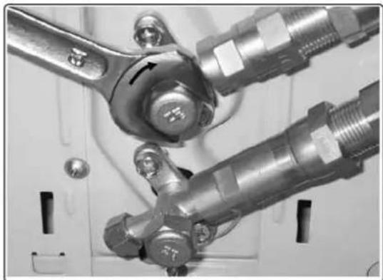
natural_image
Close-up of mechanical components with metallic fittings and bolts (no visible text or symbols)natural_image
Close-up of mechanical components being held, showing hands and parts with no visible text or symbols
natural_image
Close-up of mechanical components with threaded connectors and bolts (no visible text or symbols)natural_image
Pure technical line drawing of two pipe connection diagrams without any text, numbers, or symbolsRys. 15
natural_image
3D mechanical component diagram showing a bracket with mounting holes and a central shaft (no text or symbols)Rys. 19

natural_image
Two views of an electrical enclosure showing internal components and wiring (no visible text or symbols)(1)
(2)
natural_image
Diagram of a mechanical assembly with directional arrows indicating motion or force (no text or symbols)natural_image
Technical line drawing of a mechanical component with internal flow arrows (no text or symbols)6. MONTERA INSTALLATIONSPLATTAN OCH MATA RÖRLEDNINGEN IGENOM.
6.1 Montera monteringsplattan på den inre enheten.

WARNING!
natural_image
Close-up of industrial machinery with metal rods and wiring (no visible text or symbols)natural_image
Two black-and-white photos showing hands operating a mechanical device with labeled parts (no visible text or symbols)natural_image
Close-up of a hand holding a long cylindrical object in a kitchen setting (no visible text or symbols)natural_image
Interior view of a room with a wall-mounted air conditioner unit and a black strip (no visible text or symbols)natural_image
Close-up of electronic components including a metallic connector and a black cable with a grid pattern (no visible text or symbols)natural_image
Close-up of a mechanical tool with a curved handle and black end caps, resting on a plain surface (no text or symbols visible)natural_image
Close-up of a white and black elongated object with a dark horizontal stripe, possibly part of a mechanical or architectural component (no visible text or symbols)natural_image
Diagram of a device with a fan and internal components, showing a close-up of the next component (no text or symbols present)natural_image
Two-panel image showing hands adjusting a pipe fitting with a valve, and a close-up of the pipe fitting being held (no text or symbols visible)natural_image
Close-up of hands adjusting a metallic pipe fitting with a valve handle (no text or symbols visible)natural_image
Close-up of two mechanical pipe fittings with numbered components and directional arrows (no text or symbols)| Storlek på kopplingen (sista 2 nummer på delen) | Kilopondmeter (1bf-ft) | Newtonmeter (N-m) | Kilogram-force meter (kgf-m) |
| -06 (9,5 mm streckstorlek) | 18 - 20 24,4 - 27,1 2,4 - 2,7 | ||
| -08 (12,7 mm streckstorlek) | 30 - 35 40,6 - 47,4 | 4,1 - 4,8 | |
| -12 (19,1 mm streckstorlek) | 45 - 50 61,0 - 67,7 | 6,2 - 6,9 | |
| -16 (25,4mm streckstorlek) | 60 - 65 81,3 - 88,1 | 8,2 - 8,9 |
natural_image
Mechanical assembly diagrams showing pipe connections and valve mechanism (no text or labels)
natural_image
Close-up of mechanical components with metallic fittings and connectors (no visible text or symbols)natural_image
Close-up of mechanical components being held, showing a hand holding a tool (no visible text or symbols)
natural_image
Close-up of mechanical components with metallic rods and bolts, no visible text or symbolsnatural_image
Pure technical line drawing of two U-shaped pipe fittings with hatched walls and ground, no text or symbols presentFigur 15

natural_image
Pure technical line drawing of a pipe connection with no text or symbols10. ANSLUTA ELKABLARNA.
Figur 19
natural_image
Two open electrical boxes with internal wiring and components, labeled 'X' (no text or symbols on the boxes themselves)Distributed in Europe by PVG Holding B.V.
Benötigen Sie weitere Informationen oder treten Probleme auf, besuchen Sie bitte unsere Website www.qlima.com, oder setzen Sie sich mit unserem Kundendienst in Verbindung (Telefonnummer auf www.qlima.com).
For alle yderligere oplysninger eller ved eventuelle problemer med apparatet henvises til www.qlima.com eller det lokale Kundecenter (telefonnumre findes i www.qlima.com).
ES Si necesita información o si tiene algún problema, visite nuestra página Web www.qlima.com, o póngase en contacto con el servicio cliente (hallará el número de teléfono en www.qlima.com).
F Si vous souhaitez obtenir des informations supplémentaires ou si vous rencontrez un problème, rendez-vous sur notre site Web (www.qlima.com) ou contactez notre service client (vous trouverez l'adresse et numéro de téléphone sur www.qlima.com).
FHN Jos haluat huoltoapua, lisätietoja tai laitteen kanssa tulee ongelmia, tutustu verkkosivustoon osoitteessa www.qlima.com tai kysy neuvoa PVG kuluttajapalvelukeskuksesta (www.qlima.com).
(68) If you need information or if you have a problem, please visit the our website (www.qlima.com) or contact our sales support (you find its phone number on www.qlima.com)
① Per informazioni e in caso di problemi, visitate il sito Web www.qlima.com oppure contattate il Centro Assistenza Clienti (per conoscere il numero di telefono, consultate www.qlima.com).
Hvis du trenger informasjon, eller hvis du har et problem med produktet, kan du gå til nettsidene www.qlima.com. Alternativt kan du kontakte med PVG' forbrukertjeneste (telefonnummeret i www.qlima.com).
NL Als u informatie nodig hebt of als u een probleem hebt, bezoek dan de onze website (www.qlima.com) of neem contact op met de afdeling sales support (adres en telefoon op www.qlima.com).
P Se necessitar de informações ou se tiver problemas, visite o Web site www.qlima.com ou contacte o Centro de Assistência (número de telefone o www.qlima.com)
PL W przypadku problemów i w celu uzyskania szczegółowych informacji odwiedź stronę internetową Qlima dostępną pod adresem www.qlima.com lub skontaktuj się z Centrum kontaktów Qlima (www.qlima.com)
s Om du behöver service eller information eller har problem med apparaten kan du besöka www.qlima.com eller kontakta Qlima kundtjänst (du hittar telefonnumret på www.qlima.com).
⑤L0 Če želite dodatne informacije, obiščite spletno mesto podjetja na naslovu www.qlima.com ali pokličite na telefonsko (www.qlima.com).
Daha fazla bilgiye ihtiyaç duyarsanız veya bir sorunla karşılaşırsanız, www.qlima.com adresindeki Qlima Internet sitesini ziyaret edin veya ülkenizde bulunan Qlima müşteri merkeziyle iletişim kurun (telefon numarasını: www.qlima.com).


- VIGTIG MEDDELELSE:
- MONTERING AF INSTALLATIONSPLADEN OG TILF∅RSEL AF R∅RLEDNING.
- ASENNUSLEVYN ASENNUS JA PUTKITUKSEN LÄPIVEDON TEKEMINEN
- Internet:
- WARNING!
- DO NOT INSTALL UNLESS YOU ARE CERTIFIED:
- CONTENT
- SAFETY PRECAUTIONS
- WARNING
- Do not install it yourself.
- CAUTIONS
- ITEMS PACKED WITH THE UNIT
- ITEMS PACKED WITH THE UNIT (for SC42xx & SC52xx & SCJAxx19 models)
- NOTE!
- ATTENTION
- ACTIVITIES FOR INSTALLING THE AIR CONDITIONER
- CAUTION
- TIP
- DETERMINING THE LOCATION OF THE INSIDE AND OUTSIDE UNIT.
- Determining the location of the inside unit.
- Determining the location of the exterior unit.
- NOTE
- POSSIBILITIES FOR INSTALLING THE PIPING FROM THE INTERIOR UNIT TO THE EXTERIOR UNIT.
- NOTE ON PIPING ANGLE
- MOUNTING THE INSTALLATION PLATE AND MAKING THE PIPING FEEDTHROUGH.
- Mounting the installation plate of the interior unit.
- REMARK
- SC 4248 / SC 5248 / SCJA 4819
- Drilling the piping, condensation hose and cable feed-through.
- CONNECTING THE COOLANT PIPES
- Connecting and disconnecting the coolant pipes
- TOOLS NEEDED
- IMPORTANT INFORMATION
- CONNECTING THE REFRIGERANT PIPES TO INDOOR UNIT
- REFRIGERANT PIPING CONNECTION
- CONNECTION THE CONDENSATION DRAINAGE HOSE
- Connection the condensation discharge hose to the interior unit.
- Drain joint installation
- ELECTRICAL WORK
- CONNECTING THE ELECTRICAL CABLES.
- Connecting the electrical cables to exterior unit.
- TAKE CARE
- The wire connection between indoor unit and outdoor unit.
- Connecting the electrical cables for the interior unit.
- CHECK FOR COOLANT LEAKAGE
- POSSIBILITIES FOR LEAK CHECK AIR CONDITIONER
- TEST RUNNING AFTER INSTALLATION
- VIKTIG INFORMASJON:
- OBS
- TIPS
- MONTERINGSPLATEN MONTERES OG R∅RLEDNINGEN GJENNOMF∅RES.
- KOBLE TIL KJ∅LEMIDDELR∅RENE.
- KOBLING AV KJ∅LEMIDDELR∅RENE TIL INNEDELEN
- ZAMONTOWANE PŁYTY MONTAŻOWEJ I OZNACZENIE PRZEJŚĆ
- MONTERA INSTALLATIONSPLATTAN OCH MATA RÖRLEDNINGEN IGENOM.
- Montera monteringsplattan på den inre enheten.
- ANSLUTA ELKABLARNA.
- Distributed in Europe by PVG Holding B.V.
Brand : QLIMA
Model : SC 5232
Category : Air conditioner