
SWK 360 A1 - Action Camera SILVERCREST - Free user manual and instructions
Find the device manual for free SWK 360 A1 SILVERCREST in PDF.

| Product Type | Action Camera |
| Brand | SilverCrest |
| Model | SWK 360 A1 |
| Dimensions (approx.) | 60 x 40 x 25 mm |
| Weight (approx.) | 60 g |
| Power Source | Rechargeable Lithium-Ion battery, 3.7V, 1000 mAh |
| Video Resolution | 1080p Full HD at 30fps |
| Photo Resolution | 12 Megapixels |
| Field of View | 360 degrees (spherical) |
| Storage | MicroSD card (up to 32GB, not included) |
| Connectivity | Micro USB, Wi-Fi |
| Waterproof Rating | IPX4 (splash-proof) without housing; optional waterproof case available separately |
| Mount Compatibility | Standard tripod mount (1/4 inch) |
| Main Functions | Video recording, photo capture, time-lapse, loop recording, motion detection |
| Care and Cleaning | Wipe with a soft, dry cloth. Avoid harsh chemicals. Keep lens clean. |
| Safety Precautions | Do not disassemble. Avoid extreme temperatures. Keep away from children. |
| Spare Parts / Repairability | Battery, USB cable, and mounts available from SilverCrest. Not user-serviceable internal parts. |
| General Information | Designed for outdoor activities. Includes remote control (optional). |
Frequently Asked Questions - SWK 360 A1 SILVERCREST
User questions about SWK 360 A1 SILVERCREST
0 question about this device. Answer the ones you know or ask your own.
Ask a new question about this device
Download the instructions for your Action Camera in PDF format for free! Find your manual SWK 360 A1 - SILVERCREST and take your electronic device back in hand. On this page are published all the documents necessary for the use of your device. SWK 360 A1 by SILVERCREST.
USER MANUAL SWK 360 A1 SILVERCREST
natural_image
Close-up of a Silver Crest industrial sensor device with mode and control buttons (no readable text beyond branding)360° PANORAMA CAMCORDER SWK 360 A1
GB IE NI
360° PANORAMA CAMCORDER
Operating instructions and safety instructions
DE AT CH
360°-PANORAMA-CAMCORDER
Before reading, unfold both pages containing illustrations and familiarise yourself with all functions of the device.
DE AT CH
Operating instructions and safety instructions
Page 1
Information about these operating instructions 3
Copyright 3
Notes on trademarks 3
Intended use 4
Warnings 4
Safety 5
Basic safety instructions 5
Notes on batteries and rechargeable batteries 7
Possible infringements of third party rights 8
Description of components 10
Operation 11
Check package contents 11
Disposal of packaging 12
Inserting/removing the battery 13
Removing/attaching the side compartment cover 14
Charging the battery 15
Inserting/removing a memory card 16
Inserting/replacing the battery in the remote control 17
Handling and operation 18
Switching the camera on/off 18
Main screen - views 18
Using the camera menu 19
System configuration 20
Function settings 21
Video mode 23
Slow-motion mode 24
Photo mode 25
Capturing videos and photos 26
Transferring/playing back captures on a computer....27
Using the camera as a PC camera 28
Using the app 29
Downloading the SWK360 app 29
Connecting the camera to a smartphone via Wi-Fi 29
Using the camera with the SWK360 app 30
Displaying captures via the SWK360 app 36
Uploading videos/photos to YouTube™/Facebook® via the SWK360 app .... 3 8
Accessories 40
Using the mounts 40
Using the tripod adapter 48
Using the remote control 48
Troubleshooting 49
Cleaning 50
Storage when not in use 50
Disposal 51
Disposal of the device 51
Disposal of (rechargeable) batteries 51
Appendix 52
Technical data 52
Notes on the EU Declaration of Conformity 53
Information about these operating instructions

lations on the purchase of your new device.
You have selected a high-quality product. The operating instructions are part of this product. They contain important information about safety, usage and disposal. Before using the product, please familiarise yourself with all operating and safety instructions. Use the product only as described and for the range of applications specified. Keep these operating instructions as a reference and store them near the product. Please pass on all documentation incl. these operating instructions to any future owner(s), if you sell this product or give it away.
Copyright
This documentation is protected by copyright. Any copying or reproduction, including in the form of extracts, or any reproduction of images (even in a modified state), is permitted only with the written authorisation of the manufacturer.
Notes on trademarks
■ USB® is a registered trademark of USB Implementers Forum, Inc.
■ Apple® and the Apple logo are registered trademarks of Apple Inc., Cupertino Calif., US.
■ iOS is a registered trademark of Apple Inc. in the USA and other countries.
■ Android™ is a registered trademark of Google Inc.
■ App Store® is a service mark of Apple Inc.
■ Google Play ^TM is a registered trademark of Google Inc.
■ YouTube™ is a registered trademark of Google Inc.
■ Facebook® and the Facebook logo are registered trademarks of Facebook, Inc. in the USA and other countries.
■ Huawei® is a registered trademark of Huawei Technologies Co., Ltd.
■ iPhone® is a registered trademark of Apple Inc.
The SilverCrest trademark and the retail name are the property of their respective owner. All other names and products may be trademarks or registered trademarks of their respective owner.
Intended use
This device is an information technology device and is intended for digitally recording videos and photos and also transferring these to smartphones via Wi-Fi. The device is not intended for any other purpose, nor for use beyond the scope described. The device is not intended for use in commercial or industrial environments. The manufacturer accepts no responsibility for damage caused by failure to observe these instructions, improper use or repairs, unauthorised modifications or the use of unapproved replacement parts. The operator bears sole liability.
Warnings
The following warnings are used in these operating instructions:

DANGER
A warning notice at this hazard level indicates an imminently hazardous situation.
Failure to avoid this hazardous situation could result in serious injuries or even death.
▶ Follow the instructions in this warning notice to avoid the risk of death or serious injury.

WARNING
A warning at this hazard level indicates a potentially hazardous situation.
Failure to avoid this hazardous situation could result in injury.
▶ Follow the instructions in this warning notice to prevent injury.
CAUTION
A warning notice of this hazard level indicates a risk of property damage.
Failure to avoid this situation could result in property damage.
▶ Follow the instructions in this warning to prevent material damage.
NOTE
▶ A note provides additional information that makes handling the device easier for you.
Safety
This section contains important safety instructions for using the device.
This device complies with statutory safety regulations. Improper use may result in personal injury and property damage.
Basic safety instructions
To ensure safe operation of the device, follow the safety guidelines set out below:
- Check the device for visible external damage before use. Do not use a device that has been damaged or dropped.
If the cable or connections are damaged, have them replaced by authorised specialists or Customer Service.
This device may be used by children aged 8 years and above and by persons with limited physical, sensory or mental capabilities, or lack of experience and knowledge, provided that they are under supervision or have been told how to use the device safely and are aware of the potential risks. Children must not play with the device. Cleaning and user maintenance tasks may not be carried out by children unless they are supervised.
■ DANGER! Do not allow children to play with the packaging material! Keep all packaging materials away from children. There is a risk of suffocation!
■ Do not allow children to use the device unless they are being supervised. Children are not always aware of potential hazards.
■DANGER! Some of the supplied parts can be swallowed. If a part is swallowed, seek medical advice as soon as possible.
■ When attaching the device, ensure that it is firmly fixed in place and cannot fall down and injure somebody.
Never open the housing of the device. There are no parts inside the device which can be maintained. All repairs must be carried out by authorised specialist companies or by the Customer Service department. Improper repairs may put the user at risk. It will also invalidate any warranty claims.
■ Repairs to the device during the warranty period may only be carried out by a customer service department authorised by the manufacturer. Otherwise, no warranty claims will be held for any subsequent damages.
■ Defective components must always be replaced with original replacement parts. Compliance with the safety requirements can only be guaranteed by using these replacement parts.
■ Do not place any objects on the device.
The device may heat up while it is charging. Place the speaker in a well-ventilated location during the charging process and do not cover it.
Do not exert any pressure on the display. If it breaks, touching the sharp edges could cause injury.
■ The device is designed for outdoor use and is protected from drips and splashing water. The device can be submersed to a maximum of 3 metres for up to 20 minutes.
When using the device underwater, make sure that the battery compartment and the side compartment are completely closed.
- Check the rubber seals of the battery compartment and the side compartment for visible damage.
Check these every time before using the device underwater. Do not immerse the device in water if the rubber seals are damaged.
■ Do not jump into water while holding the device. Immerse the device slowly.
■ Never operate the device in the direct vicinity of open flames (e.g. candles) or in extreme environmental conditions (e.g. in an explosive atmosphere).
■ The device may not be used in areas in which there may be a build-up of explosive gases, e.g. petrol stations or similar.
■ Never subject the device to extreme heat or humidity. This applies especially to storage in a car. If the car is stationary for long periods and the weather is warm and sunny, temperatures of more than 50^ C can arise in the car interior and the glove compartment. Remove electrical and electronic devices from the vehicle.
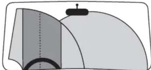
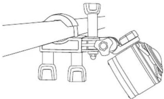
When installing the device and accessories, ensure that they do not impair steering, braking or the deployment of other vehicle systems (such as airbags) and do not restrict your field of view when driving, in accordance with the Road Traffic Act 1988 Regulations. Ensure that the suction cup of the suction cup holder does not extend more than 4 cm into the wiping range of the windscreen wipers (light grey area) and is not mounted more than 1 cm in the area directly above the steering wheel (grey area) (see diagram).
natural_image
Diagram of a mechanical or architectural component with layered surfaces and a central component (no text or symbols)DANGER! Do not place the bracket in or near the expansion area of the airbag, since the bracket could be flung through the vehicle interior in the event of airbag deployment and cause serious injuries.
DANGER! The device should not be mounted in such a way that you or other passengers could be hit by the device in the event of an accident. This could cause serious injury.
- Check regularly to ensure that the suction cup is securely attached to the windscreen. This is especially important in areas where extreme outside temperature fluctuations occur.
Do not use the suction cup on porous or uneven surfaces. Otherwise there is a risk that the device will fall off. The suction cup adheres best on smooth surfaces, e.g. glass.
All of the applicable laws in your location must be observed. The use of the device as a surveillance camera is banned in some countries and may constitute a criminal offence. The device should not be operated while driving. Traffic safety must always take priority whilst driving. Use this device only if it is not like to lead to any hazard during driving situations.
If you notice unusual noises, a burning smell or smoke coming from your device, remove the device from your body immediately. Disconnect any connected charging cable and the inserted battery immediately. Have the device checked by a qualified specialist before using it again.
Notes on batteries and rechargeable batteries

DANGER
Mishandling batteries can cause fires, explosions, leakages or other hazards!
▶ Do not throw the batteries into a fire and do not subject them to high temperatures.
▶ Never open, deform and short-circuit batteries as this can lead to chemical leakages.
▶ Check the condition of the batteries at regular intervals. Leaking chemicals can cause permanent damage to the device. Take particular care when handling damaged or leaking batteries. Risk of chemical burns! Wear protective gloves.
Chemicals which leak from a battery can cause skin irritations. In event of contact with the skin, rinse with copious amounts of water. If the chemicals come into contact with your eyes, rinse thoroughly with plenty of water, do not rub and consult a doctor immediately.
▶ When inserting batteries, note the correct polarity (plus/+ and minus/−).
▶ If you do not intend to use the device for a long time, remove the batteries.
During winter, store the replacement battery in a warm location, e.g. in your jacket pocket.
▶ Do not swallow the battery; there is a danger of chemical burns.
The device contains a button cell battery. If this button cell battery is swallowed, it can lead to serious internal burns within 2 hours that can lead to death.
▶ Keep new and used batteries away from children.

DANGER
If the battery compartment does not close securely, stop using the device and keep it away from children.
If you suspect batteries may have been swallowed or inserted into any part of the body, seek immediate medical help.
▶ Do attempt to recharge non-rechargeable batteries. There is a risk of fire and/or explosion!
Possible infringements of third party rights
Please note the following when using the camera:
Copyright
In principle, everyone owns the rights to their own image. According to copyright law, pictures of people may only be published without their permission if the affected person appears merely as an incidental feature in a landscape or other location. The question as to whether a person is merely an incidental feature must be ascertained on a case by case basis. To avoid any legal uncertainty, a warning notice about the camera should be provided in all cases in which recordings that could feature images of potentially identifiable persons are possible (see section "Duty of notification").
Protection of privacy
The privacy of others may not be infringed by any published images. Do not set up the camera so it points to the garden or an entrance of a neighbouring residence, even if these locations are easily visible from your own residence or vehicle or to the general public. This does not constitute a right to publish these views.
Personal determinability
Personal determinability exists when it can be established that a certain person was at a certain location at a certain time. This identification can be made by means of an identifier related to a specific person, e.g. a car number plate. Personal determinability of persons is to be avoided.
Surveillance cameras in the workplace
Surveillance in the workplace is subject to particularly strict legislation in Germany. Employers should not use surveillance cameras in the workplace in situation where this could lead to a possible infringement of legal rights.
Road traffic surveillance cameras
In the case of surveillance cameras directed at road traffic, it is recommended that the selection of the location of the camera and the framing of the image is to be set up so that the road users cannot be identified by means of the registration plates. Inscriptions/logos on vehicles may also serve as a means of determination of the identity of a road user.
Duty of notification
If it is not possible to preclude the identification of persons, a notification informing of the presence of the surveillance camera must be placed at clearly visible locations on all access routes to the area within the filming range of the camera. Pedestrians must also be informed that by entering the filming range of the camera they hereby give their consent to be filmed/photographed and if they do not do so then they should not access the affected area. In this case, the voluntariness of this consent must be taken into account. If the camera is located such that an affected person must pass by in order to reach a destination (e.g. at the entrance to a place of interest) then the absence of voluntariness precludes the granting of an effective consent.
The respective legal requirements of the land in which the camera is being used should always observed to avoid possible infringements of the rights of third parties.
Description of components
(For illustrations see the fold-out page)
Figure A:
① Lens cover
2 Lens
③ Wi-Fi indicator LED
4 Operating keys
⑤ Operating/charging LED
6 Display
⑦ Thread
8 Microphone
9 Speaker
10 Side compartment closure
⑪ microSD memory card slot (↑)
⑫ Micro-USB socket (↓)
13 Side compartment cover
14 Battery compartment cover lock (OPEN)
15 Battery compartment cover
16 2x lithium-ion batteries
17 USB cable (USB to micro-USB)
18 Helmet mount
19 Arm mount
20 Suction cup mount with 2 prefitted ball joint adapters
21 Rod mount
22 Ball adapter for camera
Figure B:
23 Plug connector for camera
24 Plug connector to ball joint adapter
25 Plug connector (swivel joint 90°)
26 Plug connector (swivel joint straight)
27 Plug connector (extension)
28 microSDHC memory card, speed class 1016 GB)
29 Adapter card (microSD to SD)
3D Storage box
31 Tripod adapter (mounting screw)
32 Remote control
33 Operating LED

35 Button
36 Battery compartment
37 CR2032 button cell
38 2 x Double-sided tape
39 Lens cleaning cloth
40 Storage bag
41 Operating instructions (symbol)
Operation
Check package contents
(For illustrations see the fold-out page)
◆ Remove all parts and the operating instructions from the box.
◆ Remove all packaging material.
The product includes the following components:
- 360° panoramic camera with Wi-Fi SWK 360 A1
- Lens cove① (prefitted)
• USB cable (USB to micro-USB)
- 2x lithium-ion batteries ^16
- Helmet mount ^18
Arm mount ^19
- Suction cup mount with 2 prefitted ball joint adapter ^20
- Rod mount ^21
- Ball adapter for camera ^32
- Plug connector for camera ^13
- Plug connector to ball joint adapter ^24
- Plug connector (swivel joint 90°)
- Plug connector (swivel joint straight)
- Plug connector (extension)
- microSDHC memory card, speed class⑩ (16 GB) 28
- Adapter card (microSD to SD29)
- Storage box ^30
- Tripod adapter (fastening screw)
- Remote control ^12
- CR2032 button cell
- 2 x Double-sided tap ^38
- Lens cleaning cloth ^39
- Storage bag
• These operating instructions
NOTE
▶ Check the package for completeness and signs of visible damage.
If the delivery is incomplete or damage has occurred as a result of defective packaging or during transport, contact the service hotline (see section Service).
Disposal of packaging
The packaging protects the device from damage during transport. The packaging materials have been selected for their environmental friendliness and ease of disposal, and are therefore recyclable.
Returning the packaging to the material cycle conserves raw materials and reduces the amount of waste that is generated. Dispose of packaging materials that are no longer needed in accordance with applicable local regulations.
NOTE
If possible, keep the device's original packaging during the warranty period so that the device can be packed properly for return shipment in the event of a warranty claim.
Inserting/removing the battery
◆ Push battery compartment cover lock (OPEN) ^14 downwards (see figure 01).
◆ Remove the battery compartment cover ^15 from the battery compartment. Use your fingernail or similar.
With the help of the tab, insert one of the supplied batteries ^16 into the battery compartment. This is only possible in one position (see figure 02). If you are exchanging the battery, remove the inserted battery using the tab before inserting the new battery.
♦ Push the battery16 downwards so that it clicks correctly into place.
CAUTION
▶ Check the rubber seals on the battery compartment ^15 for visible damage. Check these every time before using the camera underwater. Do not immerse the camera in water if the rubber seals are damaged.
◆ Replace the battery compartment cover ^15 in the battery compartment and push it downwards until it audibly clicks into place (see figure 03). If the battery compartment cover lock (OPEN) ^14 then automatically moves up, the battery compartment is properly closed (see figure 03). This is essential for when the camera comes into contact with water.
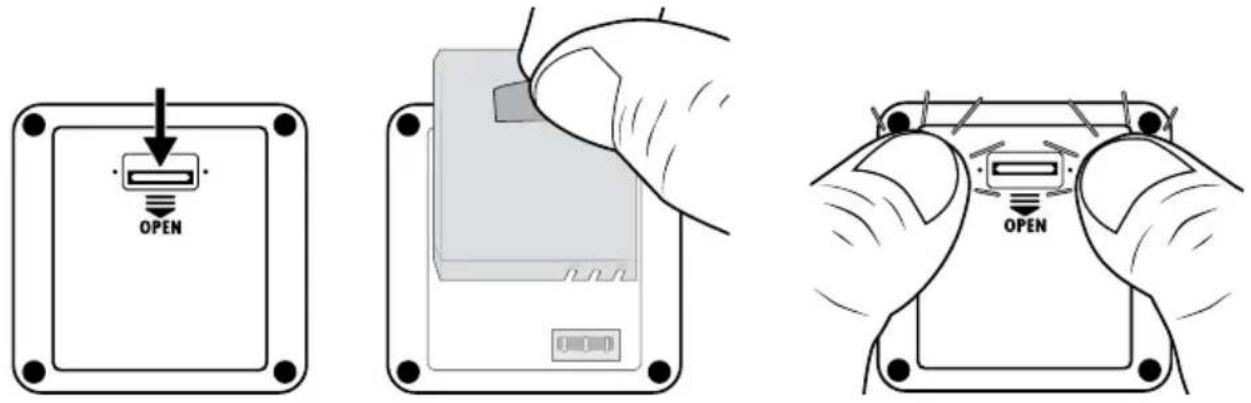
Fig. 01 Fig. 02 Fig. 03
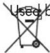
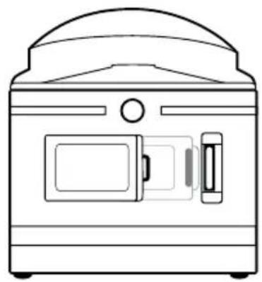
Removing/attaching the side compartment cover
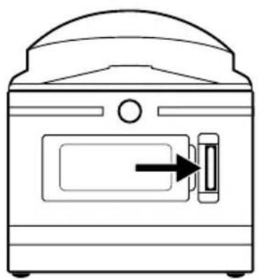
The micro-USB socket ( ) 12 and the microSD card slot ( ) 11 can be found behind the side compartment cover 13 on the camera.
♦ Push the side compartment closure forwards (see figure 04).
◆ Remove the side compartment cover ^13 from the side compartment. Use your fingernail or similar (see figure 05).
CAUTION
▶ Check the rubber seals on the side compartment ^13 for visible damage. Check these every time before using the camera underwater. Do not immerse the camera in water if the rubber seals are damaged.
◆ Replace the side compartment cover ^13 in the battery compartment and press it in until it audibly clicks into place (see figure 05).
◆ Push the side compartment closure 10 forwards to lock the side compartment cover 13 (see figure 06). This is essential for when the camera comes into contact with water.
natural_image
Line drawing of a portable oven with a door and control panel (no text or symbols)Fig. 04 Fig. 05 Fig. 06
natural_image
Line drawing of a vintage-style kitchen appliance with a door and side panel (no text or symbols)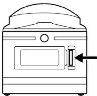
natural_image
Line drawing of a portable oven with a door and control panel (no text or symbols)Charging the battery
CAUTION
▶ Charge the camera only in dry interior spaces.
▶ Use only the supplied USB cable ^17 to charge the device!
▶ Always disconnect the USB cable when charging is complete!
Charge the supplied batteries 16 completely before using the camera. The charging process can be started with the camera switched on or off.
◆ Remove the side compartment cover from the camera (see section Removing/attaching the side compartment cover).
Connect the USB plug on the USB cable to a USB 3.0 port (blue connection) on your PC or a USB mains adapter. You can also use a USB 2.0 port. To do this, there most be at least one additional free USB port available.
Connect the micro-USB plug on the USB cable to the micro-USB port (N) in the camera. The camera switches on automatically (if not already switched on). When you connect your camera to the USB mains adapter, charging starts automatically.
When you connect the camera to your computer, press the ▼ button twice until charging mode is selected.
♦ Confirm charging mode with the OK button to start charging.
NOTE
The operating/charging LED lights up blue/red during recharging. The icon appears in the bottom right corner of the display to indicate charging. When the battery fully charged, the icon appears instead of the icon. The operating/charging LED lights up blue.
▶ Charging takes about 3.5 hours at a charging current of 1 A. When the battery is fully charged, the device can be operated for up to 60 minutes. The operating time may vary depending on usage.
The camera warms up after long periods of use. This is normal and is completely harmless.
- When the battery ^16 is empty, the icon appears on the display and the camera switches off automatically.
▶ Depending on the selected setting, the camera starts recording as soon as it is connected to a computer or a USB mains adapter.
CAUTION
▶ Close the side compartment cover ^13 as soon as the battery ^18 completely charged. This is essential for when the camera comes into contact with water (see section Removing/attaching the side compartment cover).
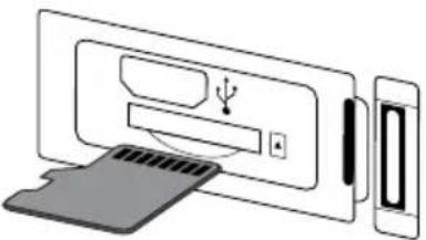
Inserting/removing a memory card
CAUTION
▶ Format any memory card before first use with the camera to ensure compatibility (see section System configuration). Back up any existing files on the memory card as these will be deleted when the memory card is formatted.
▶ To avoid malfunctions, keep the memory card away from moisture, and avoid strong vibrations, dust, heat sources or direct sunlight.
Insert the memory card as indicated by the icon on the slot. Never force the memory card into the slot. Never bend or twist the memory card. Never touch the contacts on the memory card.
▶ After transport, wait until the memory card has reached ambient temperature before using it for the first time. Major fluctuations in temperature or humidity can lead to condensation which could cause an electrical short-circuit. Keep the memory card in the storage box 30.
▶ Make sure that the camera is switched off before inserting the memory card.
NOTE
As the camera has no internal storage, it can only store captures if a memory card is inserted.
The device supports microSDHC memory cards with a capacity of up to 64 GB.
▶ Use a microSDHC card with a speed rating of 10. Using memory cards with a speed rating of less than 10 can lead to picture errors during recording.
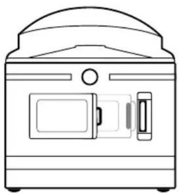
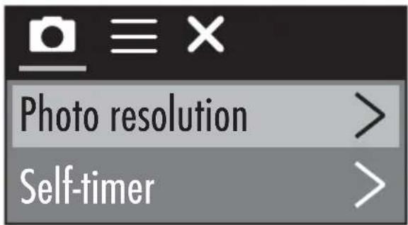
To insert the microSDHC memory card into the microSDHC memory card slot (57) the device, push it into the slot until it clicks into place. The contact surfaces of the microSDHC memory card must be facing towards the front of the camera (see figure 07).
To remove the microSDHC memory card 28 from the microSDHC memory card slot (5) in the device, press the protruding edge of the microSDHC memory card 28 in a little way until it pops out (see figure 08). Remove the microSDHC memory card 28
natural_image
Diagram showing a device with an LED and a separate screen connected to a device (no text or symbols present)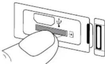
natural_image
Illustration of a hand inserting a device into a battery (no text or symbols visible)Fig. 07 Fig. 08
CAUTION
▶ Refit the side compartment cover 13 after the memory card has been inserted/removed. This is essential for when the camera comes into contact with water (see section Removing/attaching the side compartment cover).
Inserting/replacing the battery in the remote control
NOTE
Before continuing, read the section Notes on batteries and rechargeable batteries.
To insert the supplied CR2032 button cell battery ③7 or to change a battery of the same type, proceed as follows:
◆ Open the battery compartment ^36 by pushing the catch towards the battery compartment and pulling it out with a fingernail (see figure 09).
◆ Remove the old battery.
- Insert a CR2032 battery into the battery compartment ^36 . The positive terminal should face upwards (see figure 10).
◆ Push the battery compartment 36 back into the remote control 32 until it locks into place (see figure 10).
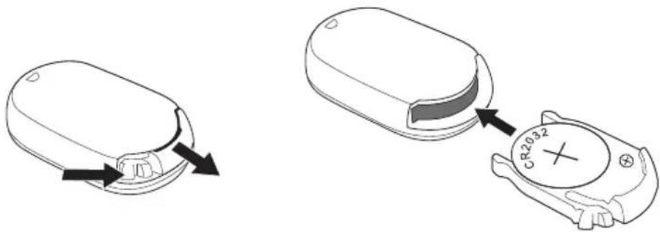
Fig. 09 Fig. 10
Handling and operation
This section provides important information about proper handling and operation of the camera.
Switching the camera on/off
◆ Press the ⏻ MODE button for 3 seconds to switch on the camera.
You will hear a short melody and the operating/charging LED 5 lights up blue.
◆ Press the ⏻ MODE button for 3 seconds to switch off the camera.
You will hear a short melody and the operating/charging LED 5 goes off.
NOTE
▶ If the camera displays the icon and switches off automatically, the battery is empty. Charge the battery or use the replacement battery to use the camera.
Main screen - views
Video mode Photo mode
Slow-motion mode System configuration

natural_image
Simple black gear icon on white background (no text or symbols)The meaning of the various symbols is explained in detail on the following pages.
Using the camera menu
- Press the ⏻MODE button to switch between video mode, photo mode, slow-motion mode and system configuration.
In video and photo mode, press the ▼ button to open the main menu for the respective modes. There are no setting options in slow-motion mode. If you press the ▼ button in slow-motion mode, the main menu of the video mode is shown. In the system configuration, however, press the OK button to open the main menu.
◆ Press the (●) ▲/≡ buttons to select the desired menu entry which you can then activate with the OK button.
Press the □/▼ buttons in the submenu to select the desired menu entry and save this with the OK button.
◆ Press the ⏻ MODE button in the submenu to leave the submenu without making any changes.
In video and photo mode main menu, press the MODE button to switch between (video mode) or (photo mode), (function settings) and (exit X)
In the system configuration main menu, press the ⏻MODE button to switch between (video mode), (photo mode), (function settings), (system configuration) and (exit).
In (system configuration), you can set you preferred language, the date and time. Set the date and time in the order year, month, day, hour, minute and seconds, as follows: You can use the ▲/▼ buttons to change the entries. Use the OK button to confirm each entry and move to the next entry. After confirming the seconds, you will automatically be returned to the main menu.
♦ Select (exit) and press the OK button to leave the main menu.
In the main screen, press the (●)▲ button to activate Wi-Fi and display the Wi-Fi information. The Wi-Fi indicator LED 3 flashes orange. Press the buto again to deactivate Wi-Fi and return to the main screen.
The Wi-Fi indicator LED ③ goes out. Read the section Connecting the camera to a smartphone via Wi-Fi to find out more about connecting the camera to a smartphone via Wi-Fi.
NOTE
▶ When the pressing the control button 4 the camera emits a beep sound.
▶ If the screensaver is active, press any button to activate the display.
System configuration
In the system configuration main screen, the display 6 shows the following view:

natural_image
Simple black gear icon on white background (no text or symbols)In the system configuration main menu, the display 6 shows the following menu entries:

| Menu entry Function | |
| Language Select your preferred language here. | |
| Date/time | Set the date and time here in the order year, month, day, hour, minute and seconds, as follows: You can use the▲/■ buttons to change the entries. Use the OK button to confirm each entry and move to the next entry. After confirming the seconds, you will automatically be returned to the main menu. |
| Memory card formatting | Select "Confirm" to format the inserted memory card. Format any memory card before first use with the camera to ensure compatibility. |
| Factory settings | Select "Confirm" to reset the camera to its default settings. |
| Firmware version | Here you can see the camera firmware information. |
Function settings
The function settings can be accessed in all modes. The settings in the function settings menu entries apply to all modes when saved.

| Menu entry Function | |
| Exposure | Select an exposure value here that corresponds to the given lighting conditions to avoid over-/under-exposure. Selection: -3, -2, -1, 0, 1, 2 or 3The negative values help to compensate for over-exposure, the positive values for underexposure. |
| White balance | Select a white balance setting on the basis of the given lighting conditions. Selection: Auto, sunny, cloudy, light bulb or fluorescent lighting |
| Wi-Fi | Select Wi-Fi to activate Wi-Fi and display the Wi-Fi information. The Wi-Fi indicator LED 3 flashes orange. Press the (b) tan to deactivate Wi-Fi and return to the menu. |
| Image rotation | Select this function to rotate the image by 180 degrees. |
| Driving mode | Choose this function, if you want to use the camera in a car with a USB connection as a surveillance camera. Optionally, you can use the cigarette lighter with a suitable USB adapter. If the function is active, the camera switches on automatically when the ignition of your car is switched on and starts recording videos. The video recording stops approx. 1 minute after you switch off the ignition. |
| Light source frequency | Select a light source frequency here depending on the usage location. Selection: Auto, 50 Hz or 60 Hz.50 Hz is standard in Europe, 60 Hz in the USA. |
| LED indicator light | When this function is activated, the operating/ charging LED 5 indicates the current status of the camera. |
| Autom. screen saver | Select here whether/when the camera's automatic screen saver is active. An active screen saver help save the camera's battery. The screen saver activates when no button on the camera has been pressed within a set period. If the screensaver is active, press any button to activate the display 6. Selection: Off, 10 s, 20 s or 30 s |
| Auto shutdown | Select here whether/when the camera should switch off automatically after extended periods of inactivity.Selection: Off, 1 minute, 3 minutes or 5 minutes |
Video mode
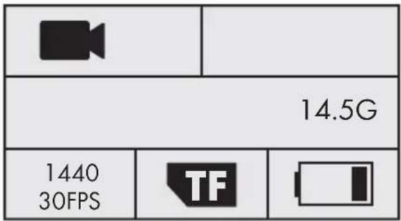
In the video mode main screen, the display 6 shows the following overview:
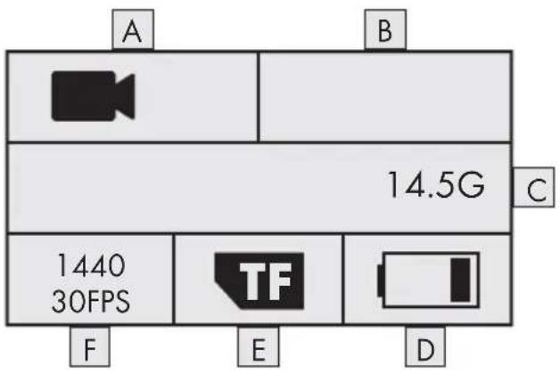
In the video mode main menu, the display 6 shows the following menu entries:
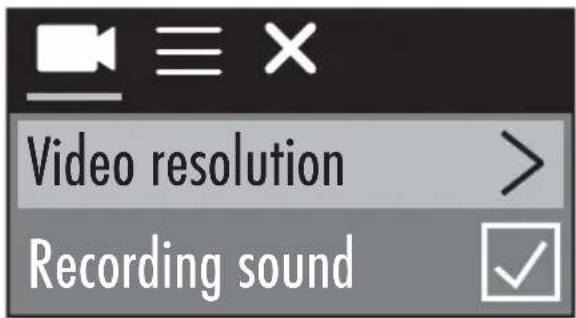
| Menu entry Function | |
| Video resolution | Select the video resolution here:2448P 30fps, 2048P 30fps, 1440P 60fps,1440P 30fps, 1072P 60fps, or 1072P 30fps |
| Recording sound | Here you can turn the sound on or off for video recording. |
| Time-lapse recording | Here you can select a time interval at which photos should be taken. The captured photos are automatically pieced together to form a video recording that spans a large period of time. It is not possible to record sound in this function. Selection: Off, 0.5 s, 1 s, 2 s, 5 s, 10 s, 30 s or 60 s |
| Loop recording | Here you can select a video length for which videos are to be continuously captured. The individual videos will be saved in the set length until recording is finished. Selection: Off, 2 minutes, 3 minutes or 5 minutes |
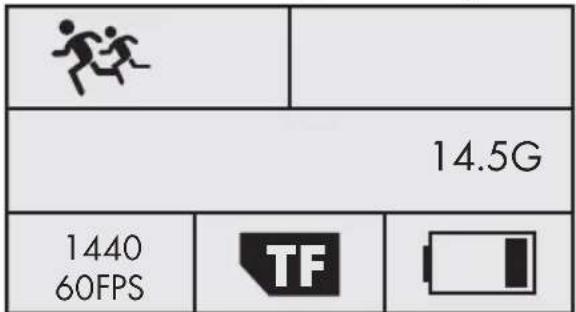
Slow-motion mode
In the slow-motion mode main screen, the display 6 shows the following overview:
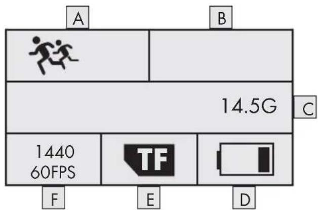
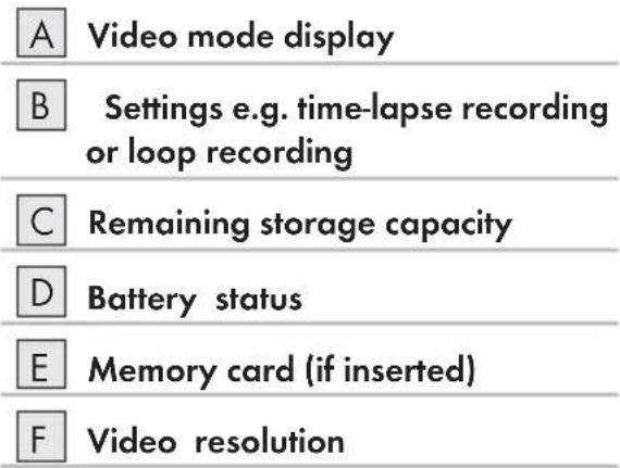
| A | Slow-motion mode display |
| B | Not used |
| C | Remaining storage capacity |
| D | Battery status |
| E | Memory card (if inserted) |
| F | Video resolution |
There is no main menu for slow-motion mode as there are no setting options. If you press the button in slow-motion mode, the main menu of the video mode is shown. Settings in video mode have no effect on slow-motion mode. Slow-motion recordings are only possible at a video resolution of 1440P 60 fps. No sound can be recorded during the capture.
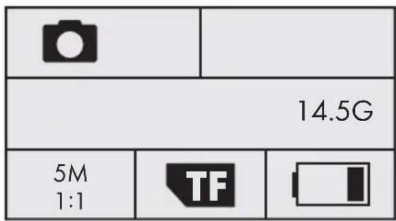
Photo mode
In the photo mode main screen, the display 📄 shows the following overview:
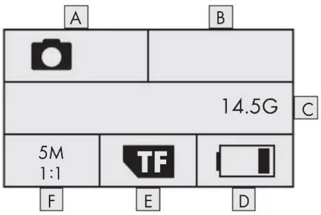
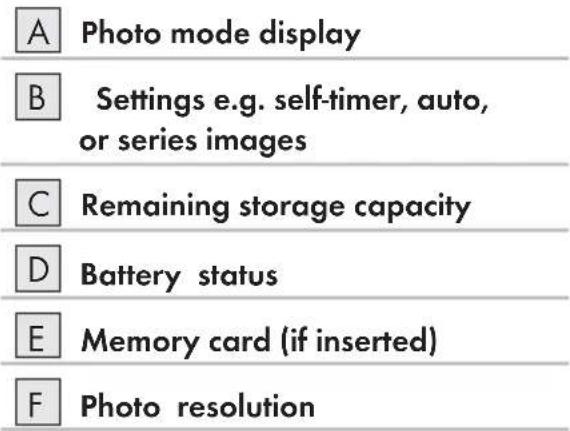
In the photo mode main menu, the display 6 shows the following menu entries:
| Menu entry Function | |
| Photo resolution | Select the photo resolution here:5 M, 8 M, (12 M or 16 M interpolated) |
| Self-timer | Here you can select the interval between pressing the OK button and triggering a capture. There is an optical and acoustic countdown. Selection:Off, 3 s, 5 s, 10 s or 20 s |
| Automatic mode | Here you can select a time interval in order to take continuous captures at this interval. There is an optical and acoustic countdown. Press the OK button to start/end the recording. Selection: Off, 3 s, 10 s, 15 s, 20 s or 30 s |
| Series images | Select how many captures should be made in series. This function is particularly suited for capturing motion sequences. Selection: Off, 3 photos, 5 photos or 10 photos |
Capturing videos and photos
Video recording and slow-motion recording
In the video and slow-motion mode main screen, press the OK button to start the recording. During the recording, the recording time is shown and the operating/charging LED flashes blue. Press the OK button again to stop the recording. If there is no more storage capacity on the memory card, the capture is stopped automatically.
NOTE
▶ During the capture, the ▼ button is inactive. If you press the (button), the recording stops automatically.
Taking pictures
In the photo mode main screen, press the OK button to take a photo (or several photos, depending on the setting). If there is no more storage capacity on the memory card, the capture is stopped automatically.
Transferring/playing back captures on a computer
You can play/transfer your captures onto a computer in two different ways.
Using a USB cable
◆ Remove the side compartment cover from the camera (see section Removing/attaching the side compartment cover).
Connect the USB plug on the USB cable to a powered-on PC.
Connect the micro-USB plug on the USB cable 17 to the micro-USB port ( ) 12 on the camera. The camera switches on automatically (if not already switched on).
USB mode is selected. Confirm USB mode with the OK button. The TF icon appears on the camera's display.
Your computer detects the memory card in the device as a "Removable Disk" and automatically installs the necessary drivers. Afterwards, you can use your file explorer to display the contents of the microSDHC memory card 28. Now carry out the required file operations.
◆ Disconnect the USB cable 17 from the camera to exit USB mode.
Using an adapter card
◆ Insert the microSD memory card ^28 in the adapter card (microSD to SD) ^29 see figure 11).
◆ Insert the adapter card (microSD to SD29 into a computer with an SD card slot.
Your computer detects the memory card as a "Removable Disk" and automatically installs the necessary drivers. Afterwards, you can use your file explorer to display the contents of the microSDHC memory card 23 Now carry out the required file operations.
NOTE
The adapter card (microSD to SD ^29 ) has a write-protect lock. To protect the microSDHC card ^28 from write access, slide the switch on the side of the card downwards (see figure 12).
The write-protect switch only protects the microSDHC memory card ^28 as long as it is in the adapter card (microSD to SD) ^29 . As soon as you remove the microSDHC memory card ^28 , the write protection will no longer be available.
natural_image
Two simple floor plan diagrams with arrows indicating movement or force direction (no text or symbols)Fig. 11 Fig. 12
CAUTION
▶ Fasten the side compartment cover 13 before you use the camera for any other purpose. This is essential for when the camera comes into contact with water (see section Removing/attaching the side compartment cover).
Using the camera as a PC camera
The camera can be used as a PC camera, e.g. with chat programs.
Remove the side compartment cover 13 from the camera (see section Removing/attaching the side compartment cover).
Connect the USB plug on the USB cable to a powered-on PC.
Connect the micro-USB plug on the USB cable 17 to the micro-USB port ( ) 12 on the camera. The camera switches on automatically (if not already switched on).
◆ Press the button once to select the PC camera option.
♦ Confirm the entry PC camera with the OK button. The 🔒 icon appears on the camera's display. Your computer automatically installs the necessary drivers.
Your camera can now be used as a PC camera.
♦ Disconnect the USB cable 17 from the camera to exit PC camera mode.
Using the app
This section provides important information about the functions and operation of the app.
Downloading the SWK360 app
You can use the SWK360 app to control the camera and all of its functions.
You can download the free app from the Apple® App Store or Google® Play.
NOTE
SWK360 app compatibility:
▶ Android 4.1 and higher
▶ iOS 8.0 and higher


natural_image
Abstract graphic with concentric circles and diagonal stripes on a black background (no text or symbols)
Connecting the camera to a smartphone via Wi-Fi
To connect the camera to a smartphone via Wi-Fi, proceed as follows:
Press the (•) button on the camera's main screen. The 📞 icon appears on the display 6. After a few seconds, the Wi-Fi information is displayed and Wi-Fi is activated. The Wi-Fi indicator LED 3 lashes orange.
Set the smartphone so that it scans for Wi-Fi devices. You can find a detailed description of how to do this in the operating instructions for your smartphone.
Select the entry SWK360_xxxxxx (xxxxxx = serial number) from the list of discovered devices on your smartphone.
◆ Enter the Wi-Fi password from the camera display to connect the two devices.
After the camera has connected to your smartphone, open the app. As soon as the app has connected to the camera, the Wi-Fi indicator LED lights up orange.
For security reasons, you will be required to enter a new password. Press the "Confirm" button.
- First enter the Wi-Fi password from the camera display, and then assign a new password. Confirm your entry to change the password.
♦ Restart the camera and activate Wi-Fi on the camera.
Select the entry SWK360_xxxxxx (xxxxxx = serial number) from the list of discovered devices on your smartphone again.
If the password query does not appear automatically, the Wi-Fi entry must first be removed and then reselected.
◆ Enter the new Wi-Fi password from the camera display to connect the two devices.
♦ Restart the app. Now you can use the full functionality of the app.
To terminate the Wi-Fi connection and deactivate the Wi-Fi, press the ▲ button on the camera. Alternatively, you can disconnect the Wi-Fi in the app in the "Settings" menu under "Wi-Fi".
NOTE
The camera needs to be reconnected to your smartphone every time the Wi-Fi connection is terminated. It may be necessary to close and reopen the app with a new Wi-Fi connection.
▶ If it is necessary to switch your smartphone to airplane mode, you will also need to make sure that the Wi-Fi on the camera is deactivated.
If you reset the camera to its factory defaults, the password will be reset. You will be required to enter a new password.
Using the camera with the SWK360 app
To use the camera with the SWK360 app, open the app on your smartphone. After the startup screen appears, the app connects to the camera.
The app has three menus: "Video/photo", "Media Gallery" and "Settings".
NOTE
▶ If there is no Wi-Fi connection between the camera and your smartphone, you can only access files that have already been downloaded in the app via the "Media Gallery" menu.
The functions shown here are from the Android version of the app. There may be slight differences with iOS devices.
▶ Slight deviations in the displays are also possible.
Video/photo menu
In the "Video/photo" menu, your smartphone will show the following overviews:
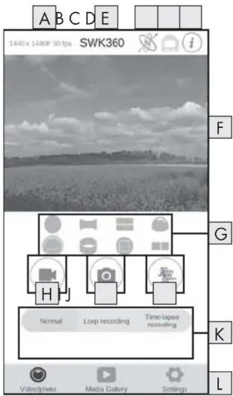
| A | Resolution |
| B | App name |
| C | Picture control |
| D | Image rotation |
| E | Information |
| F | Live view |
| G | Display modes |
| H | Video mode |
| I | Photo mode |
| J | Slow-motion mode |
| K | Settings |
| L | Menus |
| Display Description | |
| A Resolution | Depending on the mode, the set video/photo resolution is displayed here. |
| B App name | The app name is displayed here. |
| C Picture control | Press this button to control the live view or the contents of the video/photo via smartphone movement. This is only possible if you have selected "Panorama view". |
| D Image rotation | Press this button to rotate the contents of the capture by 180 degrees. |
| E Information | The version of the app and the camera software is shown here. |
| F Live view | Here you will see the live picture from the camera. The view will vary depending on the set display modes G. The live view can be operated as a touch screen, even during video recording. |
| G Display modes | ● Circular view■ Rectangle view■ 2-in-1 view● Hemisphere view● Panorama view*● Ring view■ Frontal view■ VR mode** * Press the "button to control the image via smartphone.**VR mode enables a 3D view with stereoscopic display for VR goggles such as a Google Cardboard headset. |
| H Video mode | Press the button to start or stop a video. |
| I Photo mode | Press the button to take a photo. |
| J Slow-motion mode | Press the button to start or stop a slow-motion recording. |
| K Settings | Here you can make settings in the various modes. |
| L Menus | Select here between "Video/photo", "Media Gallery" and "Settings". |
Media Gallery menu
In the "Media Gallery" menu, your smartphone will show the following overviews:
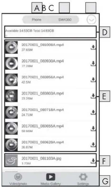
| A | View of the files in the app |
| B | View of the files in the camera |
| C | Download/delete files |
| D | Remaining storage capacity |
| E | Video captures |
| F | Photos |
| G | Menus |
| Display Description | |
| A View of the files in the app | This menu option displays files which have already been downloaded from the camera's memory card to the app. |
| B View of the files in the camera | Here you can view the files on the memory card in the camera. |
| C Download/delete files | If the "SWK360" button is activated, you can download or delete files from the memory card in the camera. If the "Phone" button is activated, you delete files that are already downloaded. |
SILVERCREST®
| Display Description | |
| D Remaining storage capacity | Here, the remaining available storage capacity of your smartphone/the memory card in the camera is displayed. |
| E Video captures | View of the video recordings |
| F Photos | View of the photos |
| G Menus | Select here between "Video/photo", "Media Gallery" and "Settings". |
Settings menu
In the "Settings" menu, your smartphone will show the following overviews:
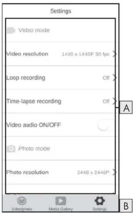
A Settings
- Video mode
- Photo mode
- Function settings
- System configuration
B Menus
| Display Description | |
| A Settings | Here you can make settings as described in the section Handling and operation. |
| B View of the files in the camera | Select here between "Video/photo", "Media Gallery" and "Settings". |
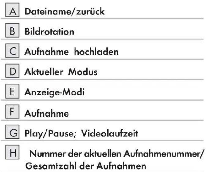
Displaying captures via the SWK360 app
Your captures are displayed in the "Media Gallery" gallery.
◆ Press the "Phone" button and select a video or photo to open it with the SWK360 player.
◆ Press the ○ button (current mode) and then the VB button.
Your smartphone displays the following overviews when you press the button (current mode) again:
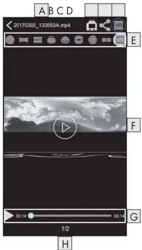
| A | File name/Back |
| B | Image rotation |
| C | Upload video/photo |
| D | Current mode |
| E | Display modes |
| F | Video/photo |
| G | Play/pause; video runtime |
| H | Number of the current capture/total number of recordings |
| Display Description | |
| A File name/Back | Here the current file name is displayed. Press the button to return to the "Media Gallery" menu. |
| B Image rotation | Press this button to rotate the contents of the video/photo by 180 degrees. |
| C Upload video/photo | You can only upload videos/photos which you have selected in the "Media Gallery" menu using the "Phone" button. The videos/photos have already been downloaded from the camera's memory card to the app.Select the display mode VR and press the "button to upload the 3D video/photo. Alternatively, you can upload your photos in 2D using the "button, you can upload your video/photo directly to YouTubeTM or Facebook® or save it on your smartphone. |
| D Current mode | Here the currently selected mode is displayed. |
| E Display modes | ● Circular view■ Rectangle view■ 2-in-1 view● Hemisphere view● Panorama view*● Ring view□ Frontal view■ VR mode**VR transcoding mode* Press the "button to control the image via smartphone.**VR mode enables a 3D view with stereoscopic display for VR goggles such as a Google Cardboard headset. |
| FVideo/photo | Here, the captured photo or video is displayed. Press this button to show/hide the respective displays. When a video is paused, you can use the ▶ button to play the video. If a photo is shown, you can use the left and right arrow to move to the next/previous photo. The photo or video can be operated as a touch screen. |
| GPlay/pause; video timeline | Here you can pause a video or resume playback. Press any point on the video timeline to resume playback from that point. |
| HNumber of the current capture/total number of recordings | Here the number of the current video/photo is shown along with the total number of videos/photos. |
Uploading videos/photos to YouTube™/Facebook® via the SWK360 app
You can upload videos and photos to YouTube™ and Facebook® directly from the app. Proceed as follows:
◆ Press on the "Media Gallery" menu button in the app.
◆ Press the "Phone" button. You can only upload photos to YouTube™ and Facebook® if they have already been downloaded to the app.
Select the videos or photos that you wish to upload. The SWK360 player opens.
◆ Press the "Current mode" button <20170302_133953A.mp4
Press the "VR transcoding mode VR" button if you want to upload your photo or video in 3D. Alternatively, you can upload your photos in 2D using the
◆ Press the "Upload" button.
Select the Facebook® or YouTube™ button to upload your video or photo to one of these platforms. Alternatively, you can cancel this operation and save the video/photo on your smartphone.
If you have selected the Facebookor YouTube™ button, the video or photo will be transcoded automatically and you will be taken to the corresponding platform.
NOTE
▶ You will need a Facebook or YouTube™ account to upload you video or photo to one of these platforms.
The transcoding speed will depend on the data-processing performance of your smartphone. Some older smartphones take a lot longer to transcode videos or photos due to their lower processor performance.
The following table shows a few examples of which data quantities can typically be transcoded in which time (can vary sometimes with other smartphone models):
| Transcoding data quantity (MB) | Typical time (min)* Typical time (min)** | |
| 100 4 3,5 | ||
| 200 | 8 | 5 |
| 300 | 12 7,5 | |
| 400 | 16 9,5 | |
| 500 | 19 11,5 | |
| 600 | 23 13,5 | |
| 700 | 27 15,5 | |
| 800 | 31 17 | |
| 900 | 35 18,5 | |
| 1000 | 40 20 | |
* Time information based on a Huawei Mate 7 and Huawei P8 (Android 6.0)
** Time information based on an Apple iPhone 6s (iOS 10.3.2)
Accessories
Using the mounts
The camera is supplied with various mounts which allow the use of the camera different situations.
NOTE
▶ You can use a Phillips screwdriver to unscrew all the screws.
Helmet mount 18

DANGER
The double-sided tape ^38 may not be used on a protective helmet as it may impair the protective effect of the helmet.
NOTE
The helmet mount is only suitable for helmets with vents.
You will need the following accessories to install the helmet mount ^18 :
natural_image
Pure electrical circuit lines without any symbols- Undo the screw on the helmet mount 18 and remove it completely from the mount.
♦ Push the plug connector to ball joint adapter 24 into the socket.
Put the screw back into the mount and then tighten it again.
- Undo the screw cap on the plug connector to ball joint adapter.
◆ Push the ball joint on the ball adapted into the screw cap on the plug connector to ball joint adapter 24
◆ Retighten the screw cap on the plug connector to ball joint adapter ^24 .
First guide the strap of the helmet mount 18 through the vents on the helmet and then through the clamps (see figure 13).
♦ Align the helmet mount18 so that it is straight on the helmet.
◆ Pull the strap tight on both sides and push the clamps downwards. The helmet mount must sit firmly on the helmet.
Adjust if required so that the straps are pulled tight.
◆ Place the thread⑦ on the camera onto the fixture of the ball adapter ② and screw the camera tight.
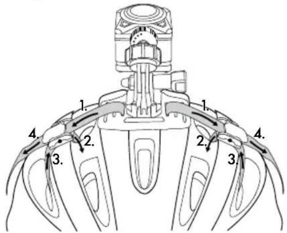
Fig. 13
NOTE
▶ You can also install the helmet mount using the plug connector 23
▶ Extend the plug connector ^25 / ^26 required or use the plug connector to ball joint adapter ^24
Optionally, you can use the following accessories for installation of the helmet mount 18:
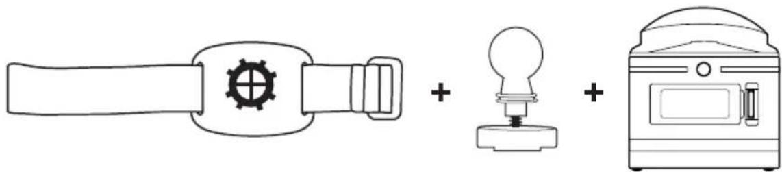
Arm mount 19
You will need the following accessories to install the arm mount ^19
natural_image
Simple line drawing of a tool, a light bulb, and a digital device (no text or symbols)- Undo the screw cap on the arm mount ^19 .
♦ Push the ball joint on the ball adapter 22 into the screw cap on the arm mount 19.
◆ Re-tighten the screw cap on the arm mount.
◆ Place the thread⑦ on the camera onto the fixture of the ball adapter ② and screw the camera tight.
◆ Press the Velcro fastener on the strap firmly at the suitable locations.
◆ Fasten the arm mount on your arm.
Adjust the Velcro of the strap so that camera is firmly in position.
NOTE
▶ To adjust the camera, undo the screw cap and move the camera into the required position. Then re-tighten the screw cap on the arm mount 19.
natural_image
Line drawing of a spray bottle dispensing liquid into a container on a stand (no text or symbols)NOTE
▶ Alternatively, you can use the double-sided tap ^38 to mount the arm mount ^19 in an object. Before assembly, remove the strap from the arm mount ^19 . When mounting the device, make sure that you apply it to a clean, fat-free and dry surface.
▶ Once you remove the double-sided tape ^38 after assembly, it cannot be reused.
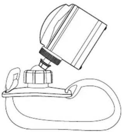
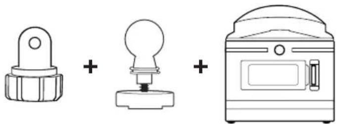
Suction cup mount 20
You will need the following accessories to install the suction cup mount 20
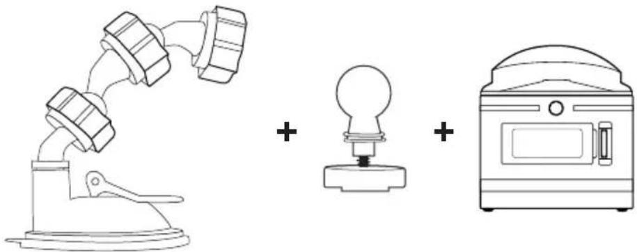
natural_image
Simple line drawing of a microscope, a light bulb, and a microwave oven with plus signs (no text or symbols)- Undo the screw cap on the suction cup mount ^20 .
♦ Push the ball joint on the ball adapte ^22 into the screw cap on the suction cup mount ^20
◆ Re-tighten the screw cap on the suction cup mount.
Place the thread ⑦ on the camera onto the fixture of the ball adapter ②2 and screw the camera tight.
NOTE
Before continuing, read the section Basic safety instructions.
◆ Push the suction cup firmly onto a window, e.g. the windscreen, and press the locking lever towards the glass pane. This creates a vacuum and the suction cup is pulled tightly against the glass. Raise the lever to remove the suction cup from the glass. The suction cup has a tab at the side, which makes it easier to remove.

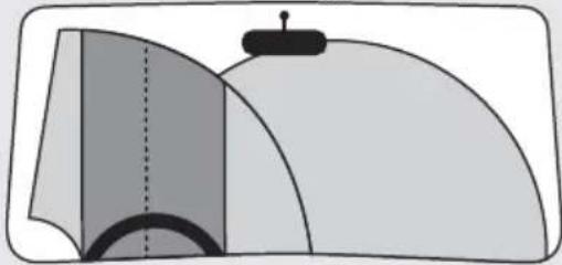
DANGER
When installing the device and accessories, ensure that they do not impair steering, braking or the deployment of other vehicle systems (such as airbags) and do not restrict your field of view when driving, in accordance with the Road Traffic Act 1988 Regulations. Ensure that the suction cup of the suction cup mount 20 does not extend more than 4 cm into the wiping range of the windscreen wipers (light grey area) and is not mounted more than 1 cm in the area directly above the steering wheel (grey area) to ensure that your field of vision is not obstructed while driving (see diagram).
natural_image
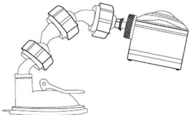
Diagram of a mechanical or architectural component with layered surfaces and a central vertical line (no text or symbols)NOTE
There are two ball joint adapters prefitted onto the suction cup mount which can be used to adjust the position of the camera or removed.
▶ To adjust the camera, undo the screw cap on one of the ball joint adapter ^20 /22 and move the camera into the required position. Then re-tighten the screw cap on the ball joint adapter ^20 . 22
natural_image
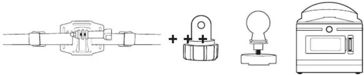
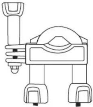
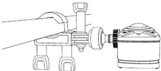
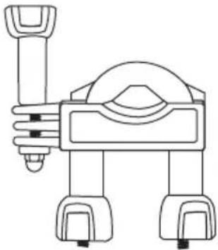
Line drawing of a mechanical device with three connected components, one mounted on a base and the other attached to a fan-like structure (no text or symbols)Rod mount 21
natural_image
Line drawing of a robot with a handle and wheels (no text or symbols)- Undo the nuts (if necessary, completely) from the rod mount 21 and remove the lower piece.
Place the upper element of the rod mount 21 around the rod and guide the lower element through both screw ends so that the rod lies on both rubber plates.
♦ Screw the nuts onto the two screw ends.
- Undo the screw on the connector and remove it completely from the mount.
NOTE
▶ You can also install the rod mount ^21 with the ball adapter ^22 for the plug connector . ^23 Optionally, both systems can be combined using the plug connector to ball joint adapter ^24
The rod moun can be mounted on a bicycle, for example.
You will need the following accessories to install the rod mount ^21 :
natural_image
Three simple line drawings: a knob, a light bulb, and a doorbell (no text or symbols)♦ Push the plug connector to ball joint adapter 24 into the socket.
◆ Unscrew the bolt using the nut.
Put the screw back into the mount and then tighten it again.
- Undo the screw cap on the plug connector to ball joint adapter24.
♦ Push the ball joint on the ball adapter 22 into the screw cap on the plug connector to ball joint adapter 24
◆ Retighten the screw cap on the plug connector to ball joint adapter.
◆ Place the thread⑦ on the camera onto the fixture of the ball adapter ② and screw the camera tight.
NOTE
To adjust the camera, undo the screw cap and/or the nut on the plug connector and move the camera into the required position. Then re-tighten the screw cap and/or the nut on the plug connector of the rod mount 21.
natural_image
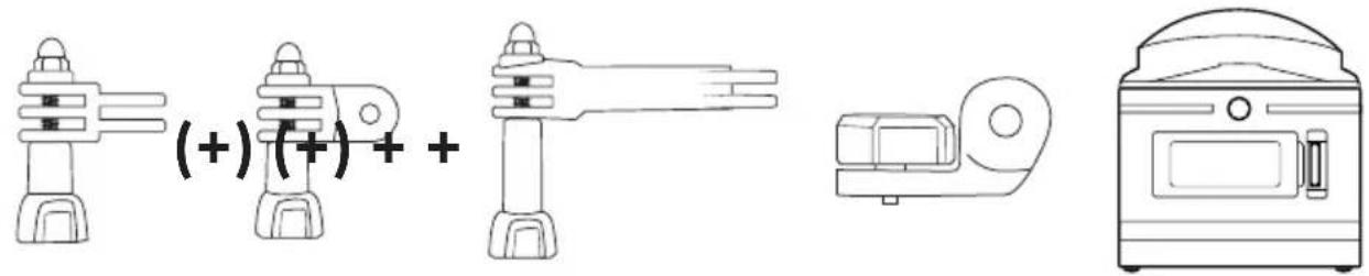
Line drawing of a robotic arm connecting a sensor to a cylindrical device (no text or symbols)Variant B plug connector 23
You will need the following accessories to install the rod mount 21:
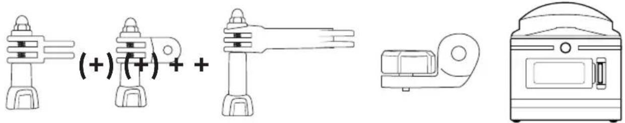
Select one of the plug connectors ^25 / ^26 . 27
◆ Push the plug connector25/26 into the fixture.
Put the screw back into the mount and then tighten it again.
NOTE
▶ Extend the plug connector ^25 / ^26 required or use the plug connector to ball joint adapter ^24
- Undo the screw on the plug connector ^25 / ^26 and remove it completely from the mount.
♦ Push the plug connector23 into the fixture.
Put the screw back into the mount and then tighten it again.
◆ Place the thread⑦ of the camera onto the fixture of the plug connector②3 and screw the camera tight.
natural_image
Line drawing of a robotic arm with articulated joints and a separate view of a mechanical component (no text or symbols)Using the tripod adapter
NOTE
The tripod adapted is suitable for all tripods with a 1/4" thread.
♦ Screw the tripod adapted into the thread on the camera.
♦ Screw the camera onto a suitable tripod.
Using the remote control
If the camera is switched on, you capture videos and photos using the remote control ^32
NOTE
▶ If the Wi-Fi connection of the camera is activated, the remote control cannot be used.
If the camera automatic screen saver is active, so that the display is inactive, briefly press the button for the button to activate the display.
▶ When you press one of the buttons on the remote control ^12 , the operating LED 3:slashes briefly.
▶ You can only capture a photo or video if the display is active.
◆ Briefly press th 🔊 button to take a photo.
Press and hold down the 📷 · 34 button for 3 seconds to start recording a video.
◆ Press and hold down the 📄·■34 button for 3 seconds again to stop the recording.
◆ Press the button briefly during video capture to stop the video recording and take a photo at the same time.
NOTE
If the camera is switched on, you can switch on the display by pressing the 35 button on the camera.
CAUTION
Damage to the remote control!
▶ Prevent the remote control from coming into contact with water.
Troubleshooting
The following table will help you to rectify minor problems:
| Fault Remedy | |
| The camera will not switch on. | ► Charge the battery16 or use the replacement battery 16 |
| The video has no sound. | ► In the settings, select the video mode with sound recording and activate this. |
| The image is too bright/dark. | ► Choose "Exposure" menu in the function settings. The negative values help to compensate for overexposure, the positive values for underexposure. |
| The image has spots and stripes. | ► Clean the lens as described in the section Cleaning. |
| There is no connection between the camera and the smartphone. | ► Proceed as described in the section Connecting the camera to a smartphone via Wi-Fi. |
| The camera is unresponsive when you press any of the buttons on the remote control. But the operating LED 33 flashes when doing so. | ► You are out of range of the camera. Move the remote control 32 clearer to the camera until the camera reacts. |
| The camera is unresponsive when you press any of the buttons on the remote control. The operating LED 33 does not flash when doing so. | ► The battery in the remote control is empty. Change the batteries as described in the section Using the remote control. |
| There are picture errors on the videos/photos. | ► Use a microSDHC card with a speed rating of 10. Using memory cards with a speed rating of less than 10 can lead to picture errors during the capture. |
| The inserted microSDHC memory card is not compatible. | ► Format the inserted microSDHC memory card as described in the section System configuration. |
Cleaning
CAUTION
Damage to the device and the remote control!
To avoid irreparable damage to the device and the remote control, ensure that no moisture can get into the device or the remote control during cleaning.
- Clean the lens regularly using the supplied cleaning cloth ^39 .
- Clean the surfaces of the device and the remote control with a soft, dry cloth. Use a normal commercial detergent and water to remove stubborn residue. Ensure that no water gets into the device or the remote control.
After using the device in salt water or dirty water, clean it immediately afterwards with clean water and then dry it.
◆ Always keep the seals on the side compartment cover ^13 and the battery compartment cover ^15 clean so that no moisture gets into the device and damages it.
Treat the seals regularly with a little rubber care product to keep them soft. This is the only way to ensure that the interior of the device is adequately protected from moisture.
◆ The suction cup on the suction cup mount must be cleaned regularly to ensure its functionality.
Storage when not in use
◆ Store the camera with the lens cover ① on in the protective bag ④0 in a dry location out of direct sunlight.
◆ Store the memory card in the storage box 30 in a dry location out of direct sunlight.
◆ To ensure a long battery life, charge the batteries at regular intervals.
Disposal
Disposal of the device

jacent symbol of a crossed-out dustbin means that this device is subject to
Directive 2012/19/EU. This directive states that this device may not be disposed of in the normal household waste at the end of its useful life, but must be handed over to
specially set-up collection locations, recycling depots or disposal companies.
This disposal is free of charge for the user. Protect the environment and dispose of this device properly.
You can obtain further information from your local disposal company or the city or local authority.
Disposal of (rechargeable) batteries
Batteries must not be disposed of in household waste. Batteries can contain poisons which are damaging to the environment. Therefore, dispose of the batteries/rechargeable batteries in accordance with statutory regulations.
All consumers are statutorily obliged to dispose of batteries at a collection site in their his community/city district or at a retail store. The purpose of this obligation is to ensure that batteries are disposed of in an environmentally congruent manner.
Only dispose of batteries when they are fully discharged.
Appendix
Technical data
| Camera | |
| Operating voltage/current 5 V | ---, 1 A via USB charging port |
| Polarity | ◎◎⊕ |
| microSDHC card slot Supports cards from 4 GB to 64 GB | |
| Recommended speed class of memory card Class 10 | |
| Integrated battery 3.7 V/1050 mAh (lithium-ion) | |
| Operating time (battery operation) approx. 60 min. | |
| Monitor | 1.0" LC display(approx. 2.5 cm screen diagonal) |
| Video resolution/frame rate | Res. 1: 2448 × 2448 pixels/30 fpsRes. 2: 2048 × 2048 pixels/30 fpsRes. 3: 1440 × 1440 pixels/60 fpsRes. 4: 1440 × 1440 pixels/30 fpsRes. 5: 1072 × 1072 pixels/60 fpsRes. 6: 1072 × 1072 pixels/30 fps |
| Video recording format MP4 | |
| Photo resolutions | Res. 1: 5 MPRes. 2: 8 MPRes. 3: 12 MP (interpolated)Res. 4: 16 MP (interpolated) |
| Photo format JPEG | |
| Capture angle | Horizontal 360° and vertical 190° ata video resolution of 2448 x 2448 pixels/30 fps |
| Immersion depth/duration max. 3 m/20 min | |
| Wi-Fi standard 802.11b/g/n | |
| Frequency band 2.4 GHz | |
| Transmission output < 10 dBm | |
| Protection type IPX 8 | |
| Working temperature +5°C to +45°C | |
| Storage temperature -5°C to +50°C | |
| Humidity (no condensation) 5 to 75% | |
| Dimensions (W x H x D) approx. 4.8 x 4.8 x 5 cm | |
| Weight (incl. battery) approx. 97 g | |
| Remote control | |
| Radio transmission 2.4 GHz | |
| Transmission output < 10 dBm | |
| Range max. 3 m | |
| Battery 1 × 3 V battery | --- type CR 2032 |
| Working temperature +5°C to +40°C | |
| Storage temperature 0°C up to +45°C | |
| Humidity (no condensation) 5 to 70% | |
| Dimensions (W x H x D) approx. 4.6 x 2.5 x 0.9 cm | |
| Weight incl. battery | approx. 11 g |
Notes on the EU Declaration of Conformity

This device complies with the essential requirements and other relevant provisions of the RE Directive 2014/53/EU and the RoHS Directive 2011/65/EU.
You can download the complete EU conformity declaration from:
www.kompernass.com/support/286389_DOC.pdf.
This appliance has a 3-year warranty valid from the date of purchase. If this product has any faults, you, the buyer, have certain statutory rights. Your statutory rights are not restricted in any way by the warranty described below.
Warranty conditions
The validity period of the warranty starts from the date of purchase. Please keep your original receipt in a safe place. This document will be required as proof of purchase.
If any material or production fault occurs within three years of the date of purchase of the product, we will either repair or replace the product for you at our discretion. This warranty service is dependent on you presenting the defective appliance and the proof of purchase (receipt) and a short written description of the fault and its time of occurrence.
If the defect is covered by the warranty, your product will either be repaired or replaced by us. The repair or replacement of a product does not signify the beginning of a new warranty period.
Warranty period and statutory claims for defects
The warranty period is not prolonged by repairs effected under the warranty. This also applies to replaced and repaired components. Any damage and defects present at the time of purchase must be reported immediately after unpacking. Repairs carried out after expiry of the warranty period shall be subject to a fee.
Scope of the warranty
This appliance has been manufactured in accordance with strict quality guidelines and inspected meticulously prior to delivery.
The warranty covers material faults or production faults. The warranty does not extend to product parts subject to normal wear and tear or fragile parts such as switches, batteries, baking moulds or parts made of glass.
The warranty does not apply if the product has been damaged, improperly used or improperly maintained. The directions in the operating instructions for the product regarding proper use of the product are to be strictly followed. Uses and actions that are discouraged in the operating instructions or which are warned against must be avoided.
This product is intended solely for private use and not for commercial purposes. The warranty shall be deemed void in cases of misuse or improper handling, use of force and modifications / repairs which have not been carried out by one of our authorised Service centres.
Warranty claim procedure
To ensure quick processing of your case, please observe the following instructions:
■ Please have the till receipt and the item number (e.g. IAN 12345) available as proof of purchase.
■ You will find the item number on the type plate, an engraving on the front page of the instructions (bottom left), or as a sticker on the rear or bottom of the appliance.
If functional or other defects occur, please contact the service department listed either by telephone or by e-mail.
- You can return a defective product to us free of charge to the service address that will be provided to you. Ensure that you enclose the proof of purchase (till receipt) and information about what the defect is and when it occurred.

You can download these instructions along with many other manuals, product videos and software on www.lidl-service.com.
Service
GB Service Great Britain
Tel.: 0871 5000 720 (£ 0.10/Min.)
E-Mail: kompernass@lidl.co.uk
IE Service Ireland
Tel.: 1890 930 034
(0,08 EUR/Min., (peak))
(0,06 EUR/Min., (off peak))
E-Mail: kompernass@lidl.ie
IAN 286389
Importer
Please note that the following address is not the service address. Please use the service address provided in the operating instructions.
KOMPERNASS HANDELS GMBH
BURGSTRASSE 21
DE-44867 BOCHUM
GERMANY
www.kompernass.com
Inhaltsverzeichnis
Einführung 59
natural_image
Diagram of a mechanical component with layered surfaces and a central pin (no text or symbols)Abb. 01 Abb. 02 Abb. 03
natural_image
Line drawing of a portable oven with a door and a right vent, no text or symbols presentAbb. 04 Abb. 05 Abb. 06
natural_image
Line drawing of a vintage-style oven with lid and door (no text or symbols)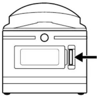
natural_image
Line drawing of a portable oven with a door and side latch (no text or symbols)Akku aufladen
ACHTUNG
natural_image
Illustration showing two steps of inserting a device into a smartphone (no text or symbols present)Abb. 07 Abb. 08
ACHTUNG
natural_image
Simple line drawing of a computer mouse with two arrows indicating rotation or move (no text or symbols)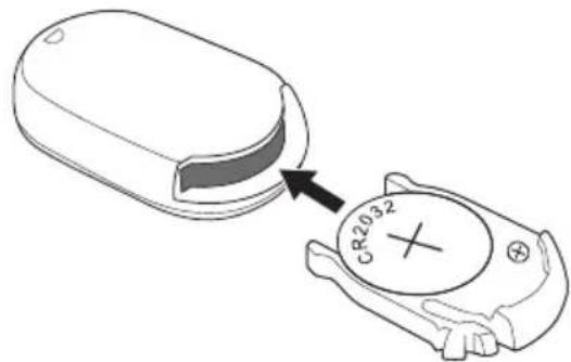
Abb. 09 Abb. 10
natural_image
Two simple floor plan diagrams with arrows indicating movement or force, no text or symbols present.Abb. 11 Abb. 12
ACHTUNG
natural_image
Abstract graphic with a white circular ring on black background, no text or symbols present
natural_image
Pure electrical circuit lines without any symbolsnatural_image
Simple line drawing of a toolbar, a gear icon, and a lamp with a lid (no text or symbols)natural_image
Line drawing of a spray bottle dispensing liquid into a container with a handle (no text or symbols)HINWEIS
natural_image
Simple line drawing of a robotic arm, a light bulb, and a microwave oven with plus signs (no text or symbols)natural_image
Diagram of a mechanical or architectural component with layered surfaces and a central knob (no text or symbols)HINWEIS
natural_image
Line drawing of a mechanical device with three arms and a base, connected to a cylindrical component (no text or symbols)Stangenhalterung 21
natural_image
Line drawing of a robot with a handle and wheels (no text or symbols)natural_image
Three simple line drawings: a pushpin, a light bulb, and a washing machine (no text or symbols)natural_image
Line drawing of a robotic arm connecting a sensor to a mechanical device (no text or symbols)natural_image
Line drawing of a robotic arm with attached mechanical components, showing hand and gear assembly (no text or symbols)Stativadapter verwenden
HINWEIS
KOMPERNASS HANDELS GMBH
BURGSTRASSE 21
DE-44867 BOCHUM
DEUTSCHLAND
www.kompernass.com
KOMPERNASS HANDELS GMBH
BURGSTRASSE 21
DE-44867 BOCHUM
GERMANY
www.kompernass.com
- 360° PANORAMA CAMCORDER SWK 360 A1
- Safety 5
- Description of components 10
- Operation 11
- Handling and operation 18
- Using the app 29
- Accessories 40
- Troubleshooting 49
- Cleaning 50
- Storage when not in use 50
- Disposal 51
- Appendix 52
- Information about these operating instructions
- Copyright
- Notes on trademarks
- Intended use
- Warnings
- DANGER
- WARNING
- CAUTION
- NOTE
- Safety
- Basic safety instructions
- Notes on batteries and rechargeable batteries
- Mishandling batteries can cause fires, explosions, leakages or other hazards!
- Possible infringements of third party rights
- Protection of privacy
- Personal determinability
- Surveillance cameras in the workplace
- Road traffic surveillance cameras
- Duty of notification
- Description of components
- Figure A:
- Figure B:
- Operation
- Check package contents
- Disposal of packaging
- Inserting/removing the battery
- Removing/attaching the side compartment cover
- Charging the battery
- Inserting/removing a memory card
- Inserting/replacing the battery in the remote control
- Handling and operation
- Switching the camera on/off
- Main screen - views
- Using the camera menu
- System configuration
- Function settings
- Video mode
- Slow-motion mode
- Photo mode
- Capturing videos and photos
- Video recording and slow-motion recording
- Taking pictures
- Transferring/playing back captures on a computer
- Using a USB cable
- Using an adapter card
- Using the camera as a PC camera
- Using the app
- Downloading the SWK360 app
- Connecting the camera to a smartphone via Wi-Fi
- Using the camera with the SWK360 app
- Video/photo menu
- Media Gallery menu
- SILVERCREST®
- Settings menu
- A Settings
- B Menus
- Displaying captures via the SWK360 app
- Uploading videos/photos to YouTube™/Facebook® via the SWK360 app
- Accessories
- Using the mounts
- Helmet mount 18
- Arm mount 19
- Suction cup mount 20
- Rod mount 21
- Using the tripod adapter
- Using the remote control
- Damage to the remote control!
- Troubleshooting
- Cleaning
- Damage to the device and the remote control!
- Storage when not in use
- Disposal
- Disposal of the device
- This disposal is free of charge for the user. Protect the environment and dispose of this device properly.
- Disposal of (rechargeable) batteries
- Appendix
- Notes on the EU Declaration of Conformity
- Warranty conditions
- Warranty period and statutory claims for defects
- Scope of the warranty
- Warranty claim procedure
- Service
- Importer
- Inhaltsverzeichnis
- Einführung 59
- Akku aufladen
- ACHTUNG
- HINWEIS
- Stangenhalterung 21
- Stativadapter verwenden
Brand : SILVERCREST
Model : SWK 360 A1
Category : Action Camera