
70-962-01 - Cables for Computers and Peripherals Extron - Free user manual and instructions
Find the device manual for free 70-962-01 Extron in PDF.


| Product Type | Fiber Optic Test Set (Power Meter and Light Source) |
| Model | 70-962-01 (FPM 101 Power Meter & FLS 101 Light Source) |
| Dimensions (each unit, excluding boot) | 4.5" H x 2.6" W x 1.0" D (11.5 cm x 6.7 cm x 2.5 cm) |
| Dimensions (including boot and connectors) | 5.5" H x 3.6" W x 1.5" D (14.0 cm x 9.1 cm x 3.8 cm) |
| Weight (FLS 101) | 0.7 lb (0.3 kg) |
| Weight (FPM 101) | 0.6 lb (0.3 kg) |
| Power Source | 2 AA batteries (alkaline or rechargeable) per unit; optional external power: FPM 101 via USB, FLS 101 via AC adapter (9 VDC, 1.5 A) |
| Battery Life (FLS 101) | Multimode: 20 hours; Singlemode: 72 hours |
| Battery Life (FPM 101) | 300 hours (with backlight off) |
| Supported Wavelengths | Multimode: 850 nm, 1300 nm; Singlemode: 1310 nm, 1550 nm |
| Measurement Units | dB, dBm, μW |
| Measurement Range (Power) | -60 to +6 dBm |
| Accuracy | ±0.25 dB at -10 dBm |
| Resolution | 0.01 dB |
| Special Features | WAVE ID (auto wavelength detection), Dual WAVE ID, tone detection/generation (2 kHz), CW mode, mandrels for multimode |
| Connector Types | LC (adapter caps for SC, FC, ST available) |
| Cleaning | Optical ports: lint-free wipes with isopropyl alcohol (99%) and filtered compressed air |
| Calibration | Recommended every 12 months |
| Warranty | 3 years parts and labor (excluding batteries) |
| Operating Temperature | +14 to +122 °F (-10 to +50 °C) |
| Safety Compliance | Class 1 LED/Laser product; EN 61010-1, EN 61326-1 |
Frequently Asked Questions - 70-962-01 Extron
User questions about 70-962-01 Extron
0 question about this device. Answer the ones you know or ask your own.
Ask a new question about this device
Download the instructions for your Cables for Computers and Peripherals in PDF format for free! Find your manual 70-962-01 - Extron and take your electronic device back in hand. On this page are published all the documents necessary for the use of your device. 70-962-01 by Extron.
USER MANUAL 70-962-01 Extron
Fiber Optic Connectors and Accessories
FPM 101 / FLS 101
Fiber Optic Test Set
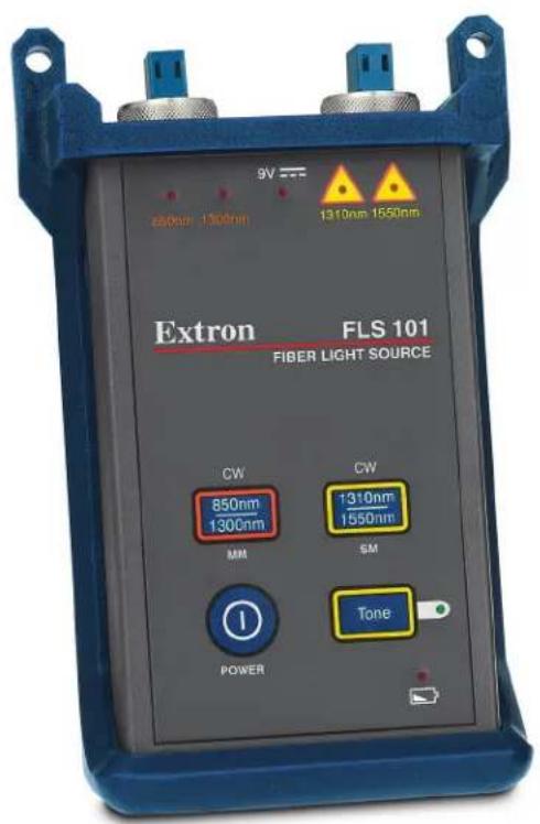
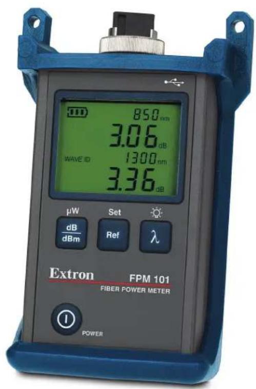
Safety Instructions • English

This symbol is intended to alert the user of important operating and maintenance (servicing) instructions in the literature provided with the equipment. This symbol is intended to alert the user of the presence of uninsulated dangerous voltage within the product's enclosure that may present a risk of electric shock.
Caution
Read Instructions • Read and understand all safety and operating instructions before using the equipment. Retain Instructions • The safety instructions should be kept for future reference. Follow Warnings • Follow all warnings and instructions marked on the equipment or in the user information Avoid Attachments • Do not use tools or attachments that are not recommended by the equipment manufacturer because they may be hazardous.
Power sources • This equipment should be operated only from the power source indicated on the product. This equipment is intended to be used with a main power system with a grounded (neutral) conductor. The third (grounding) pin is a safety feature, do not attempt to bypass or disable it.
Power disconnection • To remove power from the equipment safely, remove all power cords from the rear of the equipment, or the desktop power module (if detachable), or from the power source receptacle (wall plug).
Power cord protection • Power cords should be roused so that they are not likely to be stepped on or pinched by items placed upon or against them.
Servicing • Refer all servicing to qualified service personnel. There are no user-serviceable parts inside. To prevent the risk of shock, do not attempt to service this equipment yourself because opening or removing covers may expose you to dangerous voltage or other hazards.
Slots and openings • If the equipment has slots or holes in the enclosure, these are provided to prevent overheating of sensitive components inside. These openings must never be blocked by other objects.
Lithium battery • There is a danger of explosion if battery is incorrectly replaced. Replace it only with the same or equivalent type recommended by the manufacturer. Dispose of used batteries according to the manufacturer's instructions.
Avertissement
WARNING: Use of controls or adjustments other than those specified in this guide may result in hazardous radiation exposure.
The FLS 101 optical light source is a registered Class I LED and Laser Product.
WARNING: To avoid the danger of fire and electrical shock:
- Never use a voltage that is different from that for which the AC adapter is rated.
- Do not plug the unit into a power outlet that is shared by other devices.
- Never modify the power cord or excessively bend, twist, or pull it.
- Do not allow the power cord to become damaged. Do not place heavy objects on the power cord or expose it to heat.
- Never touch the AC adapter while your hands are wet.
- Should the power cord become seriously damaged (internal wiring exposed or shorted), contact the manufacturer to request servicing.
Use only the specified AC adapter. Use of another type of AC adapter can damage the instrument and create the danger of fire and electrical shock.
To avoid serious eye injury, never look directly into the optical outputs of fiber optic network equipment, test equipment, patch cords, or test reference cables. Always assume that optical outputs are on.
CAUTION: Proper care in handling should be taken when using any precision optical test equipment. Scratched or contaminated optical connectors can impact the performance of the instrument. It is important to keep the dust caps in place when the unit is not being used.
NOTE: Extron power meters and light sources contain no user serviceable parts. Except for changing batteries and cleaning optical ports, these units must be returned to Extron or authorized agents for repair and calibration.
Conventions Used in this Guide
TIP: A tip provides a suggestion to make setting up or working with the device easier.
NOTE: A note draws attention to important information.
CAUTION: A caution indicates a potential hazard to equipment or data.
WARNING: A warning warns of things or actions that might cause injury, death, or other severe consequences.
Copyright
© 2011 Extron Electronics. All rights reserved.
Trademarks
All trademarks mentioned in this guide are the properties of their respective owners.
Contents
Introduction.... 1
About this User Guide.... 1
About the FPM 101 and FLS 101.... 1
Features....1
Power Source....2
Typical Applications....3
Accessories 3
Operation 4
FPM 101 Power Meter — Controls and
Connections 5
Power Up the FPM 101 6
Wavelength/Backlight Button 6
dB/dBm/μW Button 6
Ref/Set Button 7
Splash and Auto-Off Screen 7
Display Readings in Test Mode 8
FLS 101 Light Source — Controls and
Connections 9
FLS 101 Power 9
Output Ports and Indicators 10
Output Wavelength Selection....10
Measuring Optical Power 11
To Measure Optical Power....11
Testing Fiber Optic Links 12
Test the Transmit Reference Cable: 12
Verify the Reference Cables:....13
Insert the Link 14
Using the Tone Generator 16
To Quickly Identify a Fiber Optic Link 16
Maintenance and Troubleshooting....17
Cleaning Optical Ports.... 17
Cleaning FPM 101 Optical Ports 17
Cleaning FLS 101 Optical Ports ....18
Repair and Calibration 18
Battery Replacement....18
Mandrels for Multimode Transmit Reference Cables 19
Loops for Singlemode Transmit Reference Cables 19
Reference Material 20
Specifications....20
Included Accessories 22
Introduction
This introduction covers the following topics: :
- About this User Guide
• About the FPM 101 and FLS 101 - Features
- Power Source
- Typical Applications
- Accessories
About this User Guide
This user guide covers the following products:
• FPM 101 Power Meter
• FLS 101 Light Source
In this guide the term “link” refers to a fiber optic cable under test. The term “power meter” refers to the FPM 101 and the term “light source” refers to the FLS 101.
Check the Extron website at www.extron.com for additional application information.
About the FPM 101 and FLS 101
The Extron Fiber Optic Test Set includes all the equipment needed to measure optical power and loss in multimode and singlemode fiber optic equipment and fiber optic cabling. The light source includes both a multimode (MM) LED output that operates at 850 nm and 1300 nm, and a singlemode (SM) laser output that operates at 1310 nm and 1550 nm. The power meter is compatible with both multimode and singlemode fiber optic cable and features an easy-to-read LCD display for measuring optical power in dBm or watts and insertion loss in dB. The test set also includes a durable padded carrying case to organize and protect the test equipment with room for the power meter, light source, reference cables, and adapters.
Features
The Fiber Optic Test Set offers:
- A complete kit for testing power and loss in multimode and singlemode fiber optic AV systems — Includes fiber optic power meter, light source, cables, adapters, and a durable canvas tool bag.
- The fiber optic light source includes both multimode and singlemode outputs — test multimode fiber at 850 nm or 1300 nm and singlemode fiber at 1310 nm or 1550 nm.
- The fiber optic power meter accepts multimode or singlemode fiber — measure power or loss at 850 nm, 1300 nm, 1310 nm, and 1550 nm wavelengths.
- Handheld, rugged, lightweight, and battery powered.
The FPM 101 Power Meter offers:
- When used with a compatible light source such as the FLS 101, WAVE ID enables the power meter to automatically detect and set wavelengths, simplifying setup.
• Power measurements in dBm or W; insertion loss in dB.
• 270 Hz, 330 Hz, 1 kHz, 2 kHz tone detection.
The FLS 101 Light Source offers:
• Integrated LED and laser light source.
- WAVE ID allows a compatible power meter to automatically identify and measure a wavelength.
- Dual WAVE ID allows a compatible power meter to automatically identify and measure two wavelengths.
• CW mode for use with power meters without WAVE ID.
• 2 kHz tone for use in fiber tracing or locating.
- 50 µm and 62.5 µm mandrels included for different diameter fiber cable.
• National Institute of Standards and Technology (NIST) traceable.
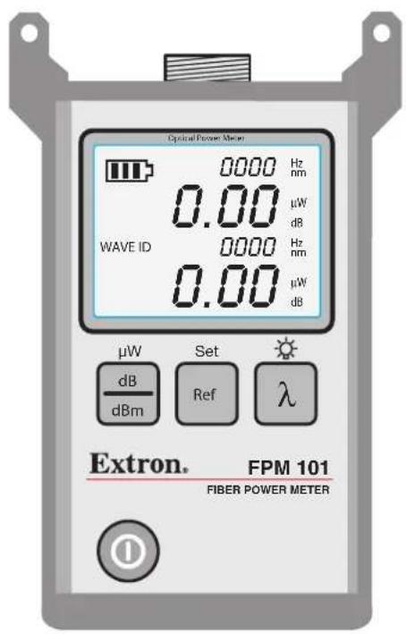
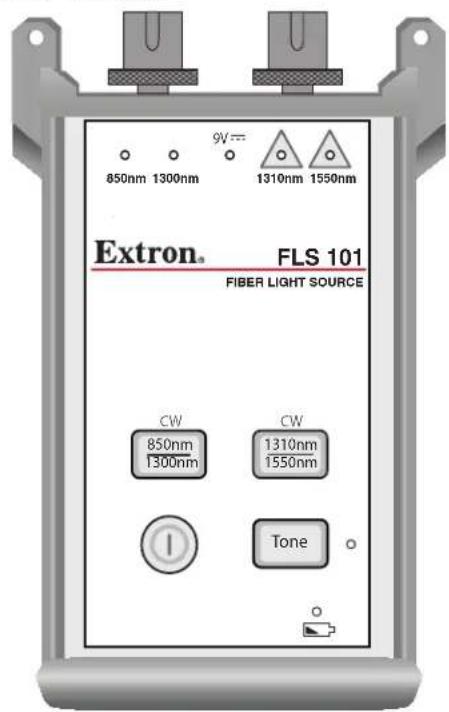
Figure 1. FPM 101 Power Meter and FLS 101 Laser Source
Power Source
The units each operate on two AA alkaline or rechargeable batteries each.
NOTE: If the battery level becomes too low, each unit turns itself off.
Typical Applications
The fiber optic test kit offers these typical applications:
FPM 101 Power Meter:
• High power model for CATV and Telco
- Enterprise/LAN for singlemode and multimode measurements
• Passive optical networks (PON) testing
• LAN/WAN multimode or singlemode networks
FLS 101 Light Source:
- Certify multimode and singlemode links per TIA/EIA standards
• Certify multimode fiber links for Gigabit Ethernet (GBE)
• Test Ethernet, Token Ring, and Fiber Distributed Data Interface (FDDI) networks
• Fiber identification before splicing
Accessories
Fiber optic test reference cables are required to connect the instruments to the fiber optic system, cable, or network under test. A test reference cable must have the same core and cladding size as the fiber under test. The connector at one end of the test reference cable must mate with the optical port on each instrument. The connector on the other end must mate with the fiber optic system under test.
LC connector adapter caps are provided for the FPM 101 and FLS 101 optical ports. One pair of singlemode and one pair of multimode reference cables with LC connectors on each end are also provided.
NOTE: Optical ports and connector end faces must be kept free from dirt or other contaminants to ensure accurate measurements and operation.
- For cleaning connector end faces on the FLS 101 light source, test reference cables, and in fiber frames or adapters, use optical quality cleaning fluid.
- For cleaning the FPM/FLS 101 optical ports and adapter caps, use lint-free optical cleaning wipes with optical quality cleaning fluid and a can of filtered compressed air.
Operation
This section details the connection of fiber optic cables to the equipment for testing and measuring the power loss of a fiber optic source.
• FPM 101 Power Meter — Controls and Connections
• FLS 101 Light Source — Controls and Connections
• Measuring Optical Power
- Testing Fiber Optic Links
- Testing Singlemode Links
• Using the Tone Generator
flowchart
graph LR
    A["Transmit Reference Cable"] --> B["Mandrel"]
    B --> C["Coupler or Bulkhead"]
    C --> D["Multimode Fiber under Test"]
    D --> E["Coupler or Bulkhead"]
    E --> F["Receive Reference Cable"]
    G["FLS 101 Fiber Optic Light Source"] --> A
    H["FPM 101 Fiber Optic Power Meter"] --> I["Digital display with 650-3.65A/4.07A power units"]
flowchart
graph LR
    A["Transmit Reference Cable"] --> B["FLS 101 Fiber Optic Light Source"]
    B --> C["Coupler or Bulkhead"]
    C --> D["Singlemode Fiber under Test"]
    D --> E["Coupler or Bulkhead"]
    E --> F["Receive Reference Cable"]
    G["FPM 101 Fiber Optic Power Meter"] --> H["Digital display with 1.45V/1.49V power range"]
Figure 2. Typical Test Connections
FPM 101 Power Meter — Controls and Connections
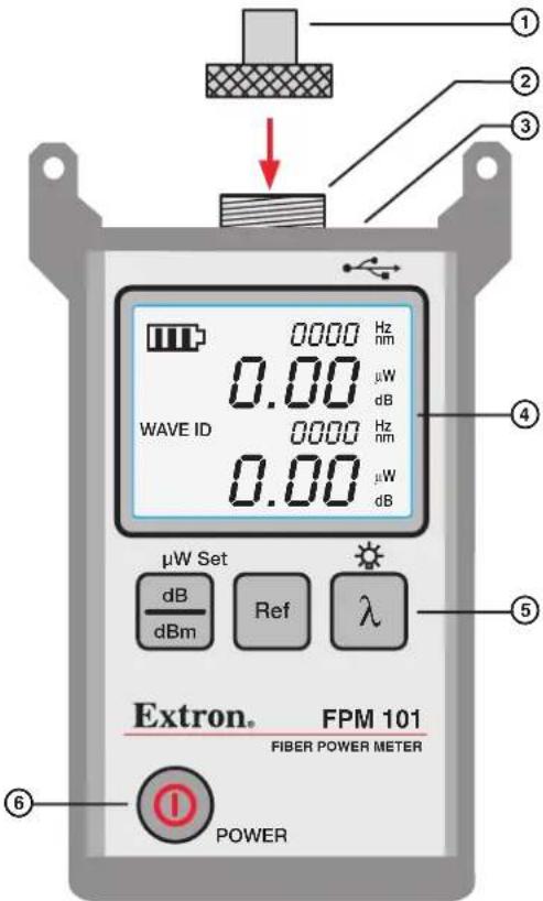
Figure 3. FPM 101 Power Meter
① Adapter Cap — Adapts the thread-on optical input to various fiber optic cable connectors. The FPM 101 includes an LC adapter cap which matches most Extron applications.
② Optical input — Accepts the thread-on adapter cap allowing you to quickly change the fiber optic connector.
③ Power adapter port (located on the top panel) — Mini-USB Type B connector for external power supply connection
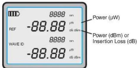
④ LCD Display — Displays the various values of the selected mode including power in dBm or uW, insertion loss in dB, calibrated wavelength, tone signal in Hz, WAVE ID, references, and battery strength.
⑤ Dual Function Buttons — Three buttons, each with primary and secondary functions, to select power measurement type, (λ), set the reference level, (Ref), and manually select the measurement wavelength, (dB/dBm). A press and release activates the function designated by the button label. Press and hold the button to activate the secondary function indicated by the text above the button.
⑥ Power Button — When the meter is off, press and hold for a short time to toggle it on. When the meter is on, press to turn off, or press and hold to toggle the auto-off feature on or off (see "Power Up the FPM 101" on page 6).
Power Up the FPM 101
The power button provides two functions:
- Press and hold the power button, Ⓞ, for a short time until the display lights up to turn the meter on. When the meter is on, press and release the button to turn the FPM 101 off.
-
Press and hold the button when the meter is on to disable/enable the auto-off feature. Auto-off powers down the unit after five minutes of inactivity.
-
If the auto-off feature is enabled, (default), press and hold the power button until HELD pON appears on the display.
- If the auto-off feature is disabled, press and hold the power button until HELD AOFF appears on the display.
Wavelength/Backlight Button
The wavelength/backlight button, provides two functions:
- Press and hold to toggle the backlight on or off.
- To manually select a wavelength, press and release to cycle through the wavelengths as shown.
850 nm >1300 nm >1310 nm >1490 nm >1550 nm >850 nm ...
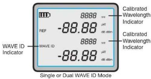
NOTE: When using the FLS 101 set to a WAVE ID output, the FPM 101 automatically switches to the WAVE ID wavelength. The WAVE ID indicator appears on the display and the wavelength is displayed in the calibrated wavelength indicator field.
dB/dBm/μW Button
The dB/dBm/uW button, , provides two functions:
- Press and release to toggle display readings between insertion loss (dB) or power (dBm).
- Press and hold to view power in microwatts (μW).
Single and Dual WAVE ID mode
Ref/Set Button
The Ref/Set button, Ref, provides two functions:
- Press and hold to store the power level values for a set of reference cables, (Set),
- Press and release to display previously stored references, (Ref).
Test Mode: To Set a Reference
- Refer to the sections describing connection of reference cables (see "Testing Fiber Optic Links" on page 12).
- Set the FPM 101 to the desired measurement mode (dBm or uW) (see "dB/dBm/μW Button" in the previous section).
- To store the currently measured level or multiple levels (in dual WAVE ID mode) as the new reference level, press and hold the Ref/Set button until HELDSET is displayed.
- Once the new reference is set, the FPM 101 switches to insertion loss (dB) mode.
NOTE: When setting references from dual WAVE ID sources, additional time is required for the power meter to identify and measure both wavelengths. Allow several seconds before pressing the Ref/Set button in step 3.
Test Mode: To View the Reference
- Press the Ref/Set button to display the stored reference wavelength and power level for the currently selected wavelength or detected WAVE ID wavelengths. The reference indicator (①, below) lights, and the reference values are displayed briefly (several seconds) as follows:
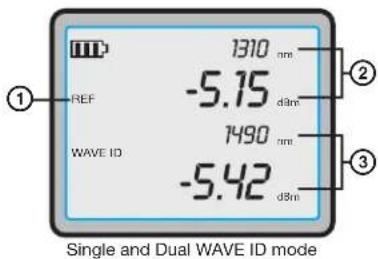
Continuous Wave (CW) mode — The reference wavelength and power level are displayed at ②
Single WAVE ID mode — The reference wavelength and power level are displayed at ②
Dual WAVE ID mode — The first reference wavelength and power level are displayed at ②, and the second at ③.
Splash and Auto-Off Screen
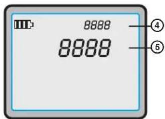
Splash (Version) Screen — During power up, the FPM 101 software version is shown on the top line, (4). The FPM 101 type and detector type are shown on the next line (5). The splash screen is replaced by the normal display after about two seconds.
Auto-off Screen — When the unit is about to power down due to inactivity, the display shows OFF for a brief time on line ⑤, then counts down the number of seconds until power is shut off.
Display Readings in Test Mode
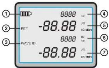
The following table lists descriptions for the LCD display readouts in various modes of operation.
Single or Dual WAVE ID mode
Figure 4. FPM 101 Display
| Item | Field Description | |
| 1 | Battery status indicator | Displays the approximate remaining battery life. Three bars indicate the charge level. When the battery indicator flashes, the batteries should be changed immediately. |
| 2 | REF indicator | Press the Ref/Set button to toggle through stored reference values. The reference values for the currently selected wavelengths are briefly displayed in the following order:CW mode: The reference value is displayed in field 5.Single WAVE ID mode: The reference value is displayed in field 6.Dual WAVE ID mode: The reference values are displayed in fields 5 and 7. |
| 3 | WAVE ID indicator Lights | When a wavelength has been identified using the WAVE ID feature with a compatible light source. |
| 4 | Wavelength | CW mode: Displays the currently selected wavelength.Single WAVE ID mode: Displays the detected WAVE ID wavelength.Dual WAVE ID mode: Displays the first detected WAVE ID wavelength. |
| 5 | Power Displays measured | power (dBm or μW), or insertion loss (dB) at the wavelength displayed in field 4.If power or loss is too high or too low for accurate measurement, this field displays HI or LO. |
| 6 | Tone / Wavelength | CW mode: Displays detected tone modulation frequency.Dual WAVE ID mode: Displays the second detected WAVE ID wavelength. |
| 7 | Power(Dual WAVE ID mode only) | Displays measured power (dBm or μW), or insertion loss (dB) at the wavelength displayed in field 6.If power or loss is too high or too low for accurate measurement, this field displays HI or LO. |
FLS 101 Light Source — Controls and Connections
The FLS 101 light source can test fiber optic links by generating the proper wavelength light for the link under test. The light source can generate multimode 850 nm and 1300 nm wavelengths, or singlemode 1310 nm and 1550 nm wavelengths. For each mode, (SM or MM), the two wavelengths can be generated one at a time or alternating between the two.
NOTE: The light source can only emit light from one output port at a time.
In WAVE ID mode, the light source emits a signal with the light allowing the FPM 101 fiber power meter to automatically determine the wavelength.

Figure 5. FLS 101 Light Source
FLS 101 Power
① Power button — Press and hold until all indicators light up to turn the FLS 101 on. The FLS 101 initially turns on in its default condition: 850/1300 nm, dual mode sending Wavelength ID (WAVE ID). After that, all settings made before the light source is turned off are retained. Press and hold again to turn the FLS 101 off.
② Power port (located on the top panel) — Connector for the AC power adapter.
③ External power indicator — Lights when the correct AC power adapter is connected.
NOTE: Whether the FLS 101 is on or not, the indicator LED stays lit as long as the adapter is connected and powered.
④ Low battery indicator — Lights when a low battery condition exists requiring battery replacement.
Output Ports and Indicators
The optical output ports require adapter caps for connection to fiber optic links and reference cables. The FLS 101 includes two LC adapter caps.
⑤ MM output port — LED source multimode optical output.
⑥ SM output port — Laser source singlemode optical output.
⑦ Active output indicators (lit when the corresponding output port is On) — The active output indicators light as follows:
| Test Mode Active Output | Indicator Status |
| WAVE ID, dual wave Corresponding wavelength indicator is lit,alternating between the two active wavelengths | |
| WAVE ID, single wave Selected wavelength indicator is lit | |
| CW or tone Selected wavelength indicator is blinking | |
Output Wavelength Selection
⑧ 850/1300/CW button — Multimode wavelength select button provides functions as follows:
WAVE ID Mode
Press and release the button to cycle through output wavelengths in the following order:
Dual 850/1300 nm > 850 nm > 1300 nm > Dual 850/1300 nm > ...
The corresponding MM active output port indicators light.
CW Mode
- Press and hold the button to switch to the CW mode. Press and hold the button again to select a single wavelength in the following order:
850 nm > 1300 nm > 850 nm > ... Release the button when the desired wavelength port indicator turns on. The selected MM active output port indicator blinks.
- Press and release the button to return to the WAVE ID mode.
⑨ 1310/1550/CW button — Singlemode wavelength select button provides functions as follows:
WAVE ID Mode
Press and release the button to cycle through output wavelengths in the following order:
Dual 1310/1550 nm > 1310 nm > 1550 nm > Dual 1310/1550 nm > ...
CW Mode
- Press and hold the button to switch to the CW mode at the current wavelength. Press and hold the button again to select a single wavelength in the following order:
1310 nm > 1550 nm > 1310 nm > ... Release the button when the desired wavelength port indicator turns on. The selected SM active output port indicator blinks.
- Press and release the button to return to the WAVE ID mode.
⑩ Tone button and Indicator —
Tone button (1550 nm, SM only) — Press the tone button to toggle the 2 kHz tone function on/off. When the tone mode is disabled, the unit returns to the WAVE ID mode at the currently selected wavelength.
NOTE: When the tone feature is active, WAVE ID is disabled and the output level is reduced by 3 dB.
Tone indicator — The Tone indicator is lit when the FLS 101 is transmitting in tone mode.
Measuring Optical Power
CAUTION: It is important to keep all optical connections and surfaces free from dirt, oils, or other contaminants to ensure proper operation. Always clean all test reference cables before conducting the test procedures outlined in this guide. See "Cleaning Optical Ports" on page 17 for details.
To Measure Optical Power
- Turn on the FPM 101 power meter by pressing the power button (①).
- Select the appropriate fiber optic reference cable. The fiber type of this cable must be the same as the fiber type normally connected to the equipment output being measured.
NOTE: Always verify that reference cable loss is not excessive (< 0.5 dB), before measuring the power output of fiber optic equipment (see "Testing Fiber Optic Links" on page 12).
- Select the adapter cap matching the reference cable connector and type.
- Connect one end of the reference cable to the adapter cap and the other end to the optical output to be measured.
- Press the wavelength button (⑥) to select the calibrated wavelength matching the nominal wavelength of the source under measurement.
- If the power meter is presently measuring insertion loss in dB, press the dB/dBm button (⑥) to display power in dBm, or press and hold it to display power in W.
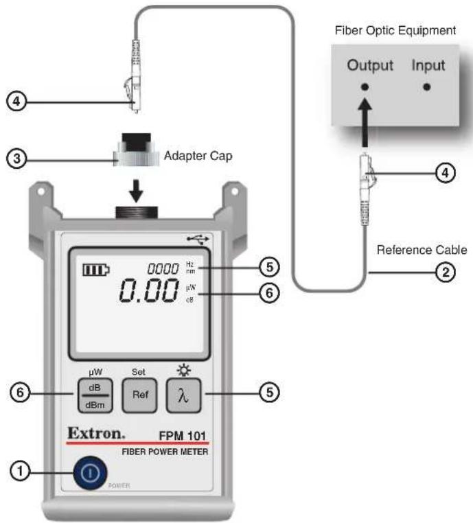
Figure 6. Power Measurement Connections
Testing Fiber Optic Links
Multimode or singlemode links are easily measured using the FPM 101 power meter and FLS 101 light source. Two reference cables, transmit and receive, are required. Before an unknown fiber link can be measured, the insertion loss of the two reference cables must first be verified to be less than 0.75 dB.
Test the Transmit Reference Cable:
- Turn on the FPM 101 power meter and FLS 101 light source. Allow the light source to stabilize for a minimum of two minutes prior to taking measurements.
-
Set the desired measurement wavelength on the FLS 101 light source, (see "Output Wavelength Selection" on page 10).
a. When using the WAVE ID feature, the FPM 101 power meter reads the wavelength automatically.
b. If not using WAVE ID, set the FPM 101 to the same wavelength as the FLS 101, (see "Wavelength/Backlight Button" on page 6). -
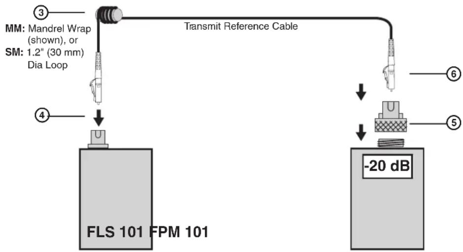
Select and prepare the transmit reference cable. The fiber type of the reference cable must match the fiber type of the link to be tested.
a. MM: Wrap and secure the reference cable five times around the included mandrel.
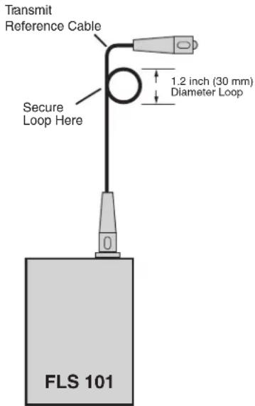
b. SM (TIA testing only): Form and secure a 1.2 inch (30 mm) diameter loop in the reference cable.
NOTE: Clean both ends of the transmit reference cable before proceeding.
-
Connect the transmit reference cable to the FLS 101 output port (MM or SM).
-
Mount an adapter cap on the power meter. The adapter cap must match the free connector on the transmit reference cable.
-
Connect the free end of the reference cable to the FPM 101. If necessary, press the dB/dBm button to display optical power in dBm, (see "dB/dBm/μW Button" on page 6).
flowchart
graph TD
    A["MM: Mandrel Wrap (shown), or SM: 1.2" (30 mm) Dia Loop"] --> B["Transmit Reference Cable"]
    C["FLS 101 FPM 101"] --> D["4"]
    D --> E["-20 dB"]
Figure 7. Transmit Reference Cable Connection
- The normal range is -20 dBm for multimode cables, 0 dBm for singlemode, (± 1dB).
NOTE: Output power for multimode cables is approximately 3 dB less when a 50 m mandrel wrapped reference cable is used, or if the tone feature is activated.
If the measured output power is outside the normal range, or the display reads HI or LO:
-
Clean all fiber connections and repeat step 6, or
• If cleaning fails, replace the transmit reference cable, then repeat steps 3 through 7 -
To store the FPM 101 reference level with the current wavelength, press and hold the Ref/Set button until HELD SET is displayed. See "Ref/Set Button" on page 7. The current levels are now the new reference levels. Once the new reference is stored, the FPM 101 automatically switches to the insertion loss measurement mode and the display reads 0 dB, ± 0.05 dB.
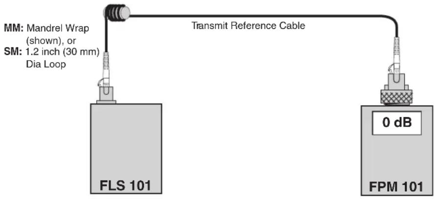
Figure 8. Transmit Reference Cable Connection After Reference Set
NOTE: To display the stored reference power levels for each wavelength, press the Ref/Set button.
When setting a reference level from multiple WAVE ID sources, allow a few seconds for the wavelengths to be identified and measured before storing the references.
Verify the Reference Cables:
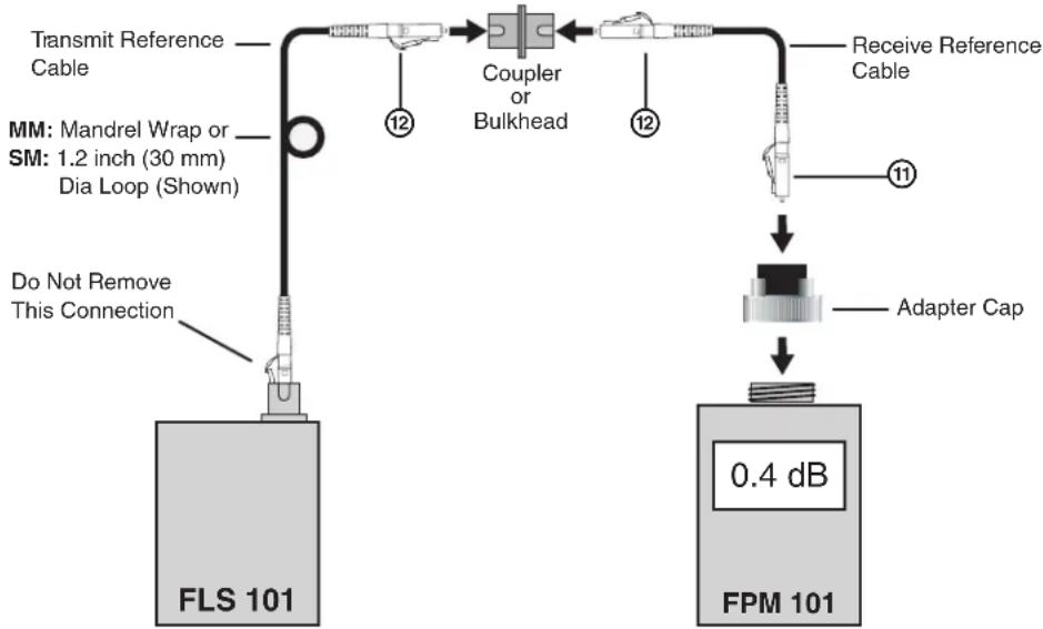
- Disconnect the transmit reference cable from the FPM 101. Do not disturb the transmit reference cable connection on the FLS 101.
-
If necessary, change the FPM 101 adapter cap to match the connector of the receive reference cable that will be connected to the power meter. Clean both ends of the receive reference cable.
-
Connect the receive reference cable to the FPM 101.
- Connect the free ends of the transmit and receive reference cables together using an appropriate coupler, or use a nearby bulkhead connector.
flowchart
graph TD
    A["Transmit Reference Cable"] --> B["Coupler or Bulkhead"]
    C["MM: Mandrel Wrap or SM: 1.2 inch (30 mm) Dia Loop (Shown)"] --> B
    D["Do Not Remove This Connection"] --> B
    B --> E["Receive Reference Cable"]
    E --> F["Adapter Cap"]
    F --> G["0.4 dB FPM 101"]
Figure 9. Connect the Receive Reference Cable
- Verify the insertion loss of the reference cable pair is less than 0.75 dB, the maximum allowed by the TIA (Extron recommends 0.4 – 0.5 dB).
If the insertion loss (dB) is not within these values:
- Disconnect the transmit and receive cables at the coupler (or bulkhead). Clean the free ends of both cables and both sides of the coupler (bulkhead), then repeat step 11 through 13.
- If the insertion loss is still not acceptable, replace both test reference cables and begin again with step 1 on page 12.
Insert the Link
- When the insertion loss is acceptable, (<0.75 dB), disconnect both the transmit and receive reference cables from the coupler or bulkhead.
NOTE: Do not disturb the reference cable connections at the light source or the power meter.
- Insert the link to be tested by connecting it to the free ends of the transmit and receive reference cables using appropriate couplings, or connect the reference cables to the bulkhead connections of the link as shown in figure 10 below.
NOTE: Clean reference cable and link ends prior to each test.
- Observe the displayed values. The link cable insertion loss is displayed in dB.
NOTE: If either the light source or power meter has shut off, turn it back on and allow to stabilize for a minimum of two minutes.
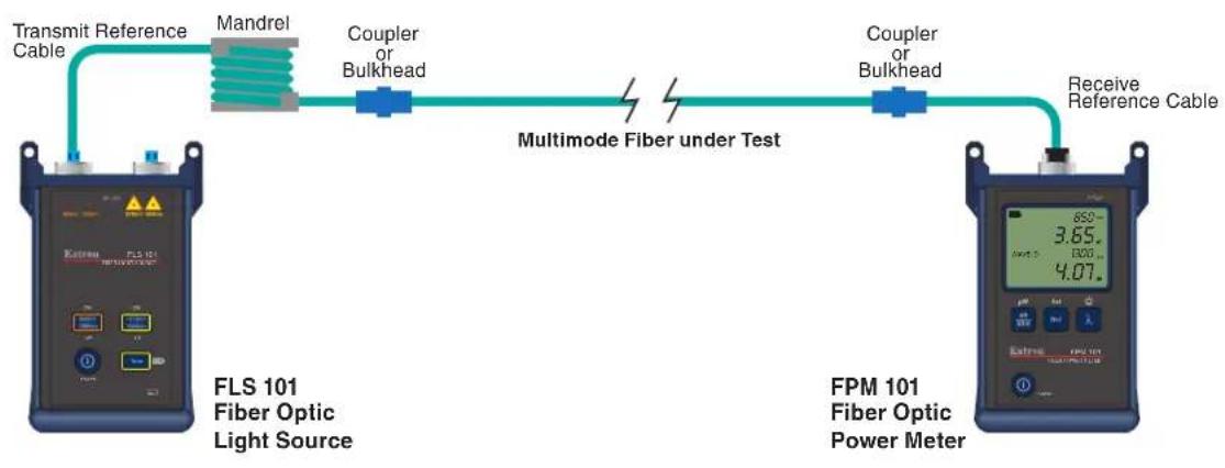
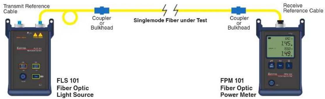
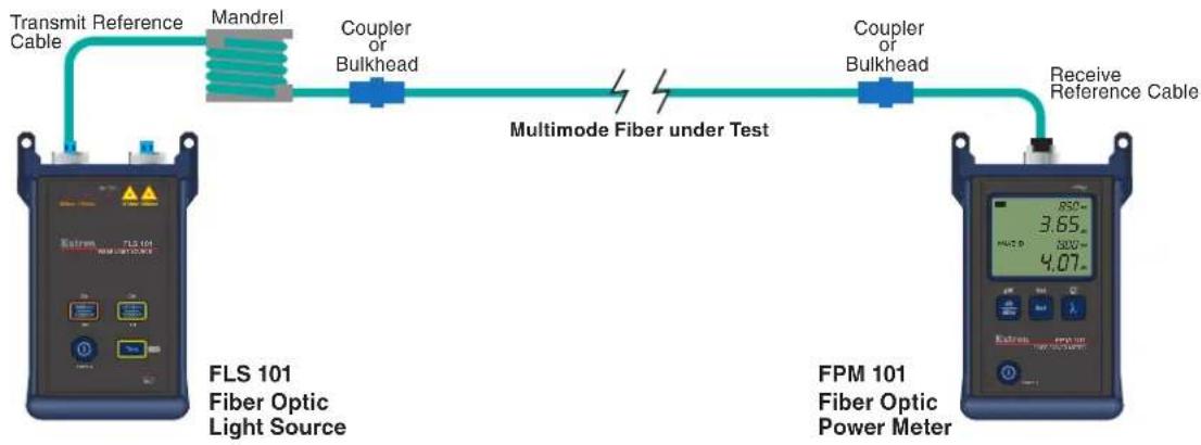
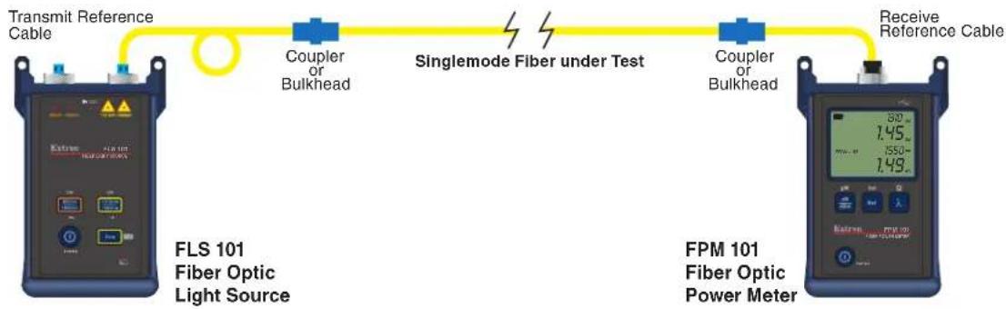
The two examples in figure 10 below show a multimode and singlemode fiber link being tested using dual WAVE ID. The insertion loss is displayed in dB.
In the multimode example, the FLS 101 is transmitting both 850 nm and 1300 nm wavelengths. The FPM 101 has automatically detected the wavelengths using WAVE ID and is reading a 3.65 dB loss for the 850 nm and 4.07 dB for 1300 nm.
The singlemode example, also using dual WAVE ID, is reading a 1.45 dB loss for the 1310 nm wavelength and 1.49 dB for 1550 nm.
flowchart
graph LR
    A["Transmit Reference Cable"] --> B["Mandrel"]
    B --> C["Coupler or Bulkhead"]
    C --> D["Multimode Fiber under Test"]
    D --> E["Coupler or Bulkhead"]
    E --> F["Receive Reference Cable"]
    G["FLS 101 Fiber Optic Light Source"] --> A
    H["FPM 101 Fiber Optic Power Meter"] --> I["Digital display with 850, 3.65, 500, 4.07"]
flowchart
graph LR
    A["Transmit Reference Cable"] --> B["FLS 101 Fiber Optic Light Source"]
    B --> C["Coupler or Bulkhead"]
    C --> D["Singlemode Fiber under Test"]
    D --> E["Coupler or Bulkhead"]
    E --> F["Receive Reference Cable"]
    G["FPM 101 Fiber Optic Power Meter"] --> H["Digital display with 30, 1.45, 1.50, 1.49"]
Figure 10. Connections to Measure Link Insertion Loss
Using the Tone Generator
The tone generator is used for fiber identification when an installer is faced with multiple unmarked links and the cable ends are not readily accessible by a single technician or are far removed from one another. The tone is inserted by the light source at one end of the link and identified at the other using the tone feature of the FPM 101.
In new installations, the link ends can be identified with the FLS 101 and FPM 101 using the WAVE ID feature and simply looking for the active link among the inactive links. However, in larger bundles that may have links carrying live data traffic, the tone generator in the FLS 101 can be used to identify spare links. The FPM 101 can differentiate between live traffic on fibers and the 2 kHz test tone generated by the FLS 101 to ensure a live fiber is not cut or disconnected causing a disruption of critical services.
To Quickly Identify a Fiber Optic Link
- Connect the light source to one end of the link to be identified. Use the appropriate reference cable and coupler.
- Select the 1550 nm wavelength using the SM button, then turn on the 2 kHz tone by pressing the tone button. The tone indicator LED lights.
- On the other end of the link, if the bulkhead is not accessible, unplug the cables one at a time and connect them into the receive reference cable using a coupler. The cable that causes the 2000 Hz display to light is the desired cable.
NOTE: Cables with live data traffic are identified by their wavelength and signal strength but they do not light the tone display.
Identifying wavelengths is not instantaneous. Always wait a few moments for the FPM 101 to identify the signal.
Mark the cable ends for reference.
Clean the connectors and couplers often.
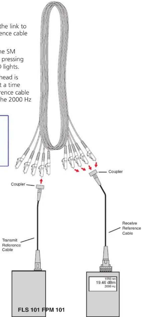
Figure 14. Tone Identification Connections
Maintenance and Troubleshooting
This section provides preventative maintenance and troubleshooting suggestions.
- Cleaning Optical Ports
• Repair and Calibration - Battery Replacement
- Mandrels for Multimode Transmit Reference Cables
- Loops for Singlemode Single Reference Cables
Cleaning Optical Ports
CAUTION: Before conducting the following procedures be certain the instruments are turned Off. Disconnect the external supply from the FLS 101.
Optical ports must be kept free from dirt or other contaminants to ensure accurate measurements and operation. Always clean reference cables before conducting the test procedures outlined in this guide. It is important to keep dust caps in place when instruments are not being used.
For cleaning connector end faces on the FLS 101 light sources, test reference cables, and in fiber frames or adapters, use optical quality cleaning fluid and molded cleaning tips.
For cleaning the FPM 101 optical ports and adapter caps, use lint-free optical cleaning wipes and optical quality cleaning fluid such as IPA -Reagent Grade Isopropyl Alcohol 99% or better) and a can of filtered compressed air.
Cleaning FPM 101 Optical Ports
- Unscrew the adapter cap from the adapter cap mount.
- Use lint-free optical cleaning wipes and optical quality cleaning fluid and dampen a portion of the wipe with the cleaning fluid.
NOTE: If using isopropyl alcohol (IPA), be sure to use 99% pure IPA that has not been contaminated.
- Gently wipe the exposed FPM 101 port starting with the wet section of the wipe and pulling it to the dry section.
NOTE: Starting with wet cleaning and finishing with dry improves cleaning action, reduces static buildup, and leaves the end-face dry.
- Using a can of filtered compressed air (held vertically), blow out any contaminants from the adapter cap.
- Once the cleaning is complete, replace the adapter cap.
Cleaning FLS 101 Optical Ports
- Rotate the adapter base counterclockwise approximately four times.
- Pull the adapter directly out and away from the adapter mount.
- Dampen an optical wipe with alcohol and gently wipe the exposed ferrule.
NOTE: Be certain to use 99% IPA that has not been contaminated.
- Dry the ferrule using a new optical wipe.
- Using a can of filtered compressed air (held vertically), blow out any remaining contaminants from the adapter.
- Replace the adapter making sure the alignment pin on the adapter aligns with the mating hole on the base.
Repair and Calibration
Repair of the test equipment in the field is not recommended.
Calibration of the test equipment is recommended every 12 months.
Contact your Extron representative for calibration or repair of the test equipment.
Battery Replacement
- Remove the protective rubber boot from the instrument.
- Remove the battery compartment cover located on the back of the instrument.
- Remove the discharged batteries.
- Observe the proper polarity and place new batteries in the compartment.
- Replace the battery compartment cover and rubber boot.
Mandrels for Multimode Transmit Reference Cables
When testing multimode links using an overfilled LED source, always wrap the transmit reference cable five (5) times around the proper diameter mandrel. This is specified by TIA/EIA-568-B and improves insertion loss measurement repeatability and accuracy. Do NOT use mandrels on multimode receive reference cables or singlemode reference cables.
| Available mandrels for test reference cables with 3 mm jackets | Diameter (D) for other jacket diameters (in mm) | 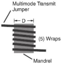 | |
| Fiber Type Part Number | |||
| 62.5 μm Contact Extron D = 20 mm minus | jacket diameter | ||
| 50 μm Contact Extron D = 25 mm minus | jacket diameter | ||
| Kit with both mandrels | Contact Extron | ||
Loops for Singlemode Transmit Reference Cables
For TIA testing of singlemode links, the transmit reference cable must have a 1.2 inch (30 mm) loop secured by tape, hook and loop fasteners, or other means. Do not pull the fastener too tight.
Reference Material
This section provides technical specifications, included and replacement part numbers, and optional accessories.
- Specifications
• Included Accessories
Specifications
NOTE: These devices are class 1 laser products. They meet the safety regulations of IEC-60825, FDA 21 CFR 1040.10, and FDA 21 CFR 1040.11.
Optical specifications — FLS 101 fiber optic output
Number/type
Singlemode 1 laser emitter
Multimode.... 1 LED emitter
Connectors 2 connectors with LC, SC FC, and ST adapters
Wavelengths
Singlemode 1310 nm ±20 nm, 1550 nm ±20 nm
Multimode.... 850 nm ±30 nm, 1310 nm -10/+50 nm
Spectral width
Singlemode 5 nm (max.) at 1310 nm and at 1550 nm
Multimode.... 40 nm (typical) at 850 nm
120 nm (typical) at 1310 nm
Transmission power
Singlemode 0 dBm, 9 μm
Multimode.... -20 dBm, 62.5 μm
NOTE: Power will be 3 dB lower if a 50 µm mandrel-wrapped jumper is used instead of a 62.5 µm mandrel-wrapped jumper.
Stability
Singlemode .... ±0.05 dB over 1 hour after 15 minute warmup
±0.1 dB over 8 hours after 15 minute warmup
Multimode.... ±0.1 dB over 8 hours after 5 minute warmup
Optical specifications— FPM 101
Wavelengths 850 nm, 1300 nm, 1310 nm, 1490 nm, 1550 nm; calibrated
Detector type ...... Germanium (Ge)
Units of measurement...... dB, dBm, μW
Testing ranges
Measurement ...... -60 to +6 dBm
Tone detection...... At 850 nm: -45 to +6 dBm
At all other wavelengths: -50 to +6 dBm
Wavelength identification ..... At 850 nm: -45 to +6 dBm
At all other wavelengths: -50 to +6 dBm
Resolution 0.01 dB
Accuracy ±0.25 dB at -10 dBm
General
Power
FLS 101 ...... Internal batteries
or
External, supplied by optional AC adapter
Input: 100-240 VAC, 50-60 Hz
Output: 9 VDC, 1.5 A, 13 watts
FPM 101.... Internal batteries
or
External
Supplied via USB port
Power consumption
FLS 101 LED transmission: 1.8 watts, 3 VDC
Laser transmission: 1.5 watts, 3 VDC
FPM 101....2.7 watts, 3 VDC with backlight on
Batteries
Number/type 2 AA batteries (1.5 V alkaline or 1.2 V rechargeable)
Operating time (nominal)
FLS 101.... Multimode operation: 20 hours
Singlemode operation: 72 hours
FPM 101 300 hours
Temperature/humidity ...... Storage: -22 to +140 °F (-30 to +60 °C) / 10% to 90%, noncondensing
Operating: +14 to +122 °F (-10 to +50 °C) / 10% to 90%, noncondensing
Cooling...... Convection, no vents
Thermal dissipation 1.1 BTU/hr
Mounting...... No
Enclosure type.... Plastic
Enclosure dimensions 4.5" H x 2.6" W x 1.0" D
(11.5 cm H x 6.7 cm W x 2.5 cm D)
(Excluding the rubber boot, connectors.)
5.5" H x 3.6" W x 1.5" D
(14.0 cm H x 9.1 cm W x 3.8 cm D)
(Including including rubber boot and connectors.)
Product weight
FLS 101 0.7 lb (0.3 kg)
FPM 101 0.6 lb (0.3 kg)
Shipping weight.... 2 lbs (1 kg)
Vibration.... ISTA 1A in carton (International Safe Transit Association)
Regulatory compliance
Safety...... EN 61010-1
EMI/EMC EN 61000-4, EN 61326-1
Warranty.... 3 years parts and labor, excluding batteries
NOTE: All nominal levels are at ±10%.
NOTE: Specifications are subject to change without notice.
Included Accessories
| Description Part Number | |
| FPM 101 power meter | |
| FLS 101 light source | |
| Batteries (4 AA) | |
| Soft Pouch | |
| LC singlemode reference cable (x2) | |
| LC multimode reference cable (x2) | |
| Light Source LC Adapter (x2) | |
| Power Meter LC Adapter Cap | |
| FPM/FLS 101 Setup Guide |
Extron® Warranty
Extron Electronics warrants this product against defects in materials and workmanship for a period of three years from the date of purchase. In the event of malfunction during the warranty period attributable directly to faulty workmanship and/or materials, Extron Electronics will, at its option, repair or replace said products or components, to whatever extent it shall deem necessary to restore said product to proper operating condition, provided that it is returned within the warranty period, with proof of purchase and description of malfunction to:
USA, Canada, South America, and Central America:
Extron Electronics
1001 East Ball Road
Anaheim, CA 92805
U.S.A.
Japan:
Extron Electronics, Japan
Kyodo Building, 16 Ichibancho
Chiyoda-ku, Tokyo 102-0082
Japan
Europe, Africa, and the Middle East:
Extron Europe
Hanzeboulevard 10
3825 PH Amersfoort
The Netherlands
China:
Extron China
686 Ronghua Road
Songjiang District
Shanghai 201611
China
Asia:
Extron Asia
135 Joo Seng Road, #04-01
PM Industrial Bldg
Singapore 368363
Singapore
Middle East:
Extron Middle East
Dubai Airport Free Zone
F12, PO Box 293666
United Arab Emirates, Dubai
This Limited Warranty does not apply if the fault has been caused by misuse, improper handling care, electrical or mechanical abuse, abnormal operating conditions, or modifications were made to the product that were not authorized by Extron.
NOTE: If a product is defective, please call Extron and ask for an Application Engineer to receive an RA (Return Authorization) number. This will begin the repair process.
USA: (714) 491-1500
Europe: 31.33.453.4040
Asia: 65.6383.4400
81.3.3511.7655
Units must be returned insured, with shipping charges prepaid. If not insured, you assume the risk of loss or damage during shipment. Returned units must include the serial number and a description of the problem, as well as the name of the person to contact in case there are any questions.
Extron Electronics makes no further warranties either expressed or implied with respect to the product and its quality, performance, merchantability, or fitness for any particular use. In no event will Extron Electronics be liable for direct, indirect, or consequential damages resulting from any defect in this product even if Extron Electronics has been advised of such damage.
Please note that laws vary from state to state and country to country, and that some provisions of this warranty may not apply to you.
| Extron USA - West Headquarters | Extron USA - East | Extron Europe | Extron Asia | Extron Japan | Extron China | Extron Middle East |
| +800.633.9876Inside USA/Canada Only | +800.633.9876Inside USA/Canada Only | +800.3987.6673Inside Europe Only | +800.7339.8766Inside Asia Only | +81.3.3511.7655+81.3.3511.7656 FAX | +400.883.1568Inside China Only | +971.4.2991800+971.4.2991880 FAX |
| +1.714.491.1500+1.714.491.1517 FAX | +1.919.863.1794+1.919.863.1797 FAX | +31.33.453.4040+31.33.453.4050 FAX | +65.6383.4400+65.6383.4664 FAX | +86.21.3760.1568+86.21.3760.1566 FAX |
- Fiber Optic Connectors and Accessories
- FPM 101 / FLS 101
- Safety Instructions • English
- Caution
- Avertissement
- Conventions Used in this Guide
- Copyright
- Trademarks
- Contents
- Introduction.... 1
- Operation 4
- Maintenance and Troubleshooting....17
- Reference Material 20
- Introduction
- About this User Guide
- About the FPM 101 and FLS 101
- Features
- The Fiber Optic Test Set offers:
- The FPM 101 Power Meter offers:
- The FLS 101 Light Source offers:
- Power Source
- Typical Applications
- FPM 101 Power Meter:
- FLS 101 Light Source:
- Accessories
- Operation
- Power Up the FPM 101
- Wavelength/Backlight Button
- dB/dBm/μW Button
- Ref/Set Button
- Test Mode: To Set a Reference
- Test Mode: To View the Reference
- Splash and Auto-Off Screen
- Display Readings in Test Mode
- FLS 101 Light Source — Controls and Connections
- FLS 101 Power
- Output Ports and Indicators
- Output Wavelength Selection
- WAVE ID Mode
- CW Mode
- Measuring Optical Power
- To Measure Optical Power
- Testing Fiber Optic Links
- Test the Transmit Reference Cable:
- Verify the Reference Cables:
- Insert the Link
- Using the Tone Generator
- To Quickly Identify a Fiber Optic Link
- Maintenance and Troubleshooting
- Cleaning Optical Ports
- Cleaning FPM 101 Optical Ports
- Cleaning FLS 101 Optical Ports
- Repair and Calibration
- Battery Replacement
- Mandrels for Multimode Transmit Reference Cables
- Loops for Singlemode Transmit Reference Cables
- Reference Material
- Specifications
- Optical specifications — FLS 101 fiber optic output
- Optical specifications— FPM 101
- Testing ranges
- General
- Power
- Power consumption
- Batteries
- Product weight
- Regulatory compliance
- Extron® Warranty
- USA, Canada, South America, and Central America:
- Japan:
- Europe, Africa, and the Middle East:
- China:
- Asia:
- Middle East:
Brand : Extron
Model : 70-962-01
Category : Cables for Computers and Peripherals