345-202 - Door closer Hard Head - Free user manual and instructions
Find the device manual for free 345-202 Hard Head in PDF.


| Product Type | Door Closer |
| Brand | Hard Head |
| Model | 345-202 |
| Dimensions (approx.) | 200 x 50 x 50 mm |
| Weight (approx.) | 1.5 kg |
| Power Source | None (mechanical) |
| Main Functions | Adjustable closing speed, backcheck, latching action |
| Closing Speed Adjustment | Yes, via adjustable valves |
| Backcheck | Yes, prevents door from slamming open |
| Latching Action | Final door closure before latch engagement |
| Door Compatibility | Interior or exterior doors, up to 90 kg |
| Mounting Type | Surface mounted (standard, top jamb, parallel arm) |
| Material | Cast iron body, steel arm |
| Maintenance | Check for oil leaks, clean arm and valves regularly |
| Safety Precautions | Ensure proper installation; keep out of reach of children |
| Spare Parts Availability | Mounting bracket, screws, arm assembly |
| Warranty | Standard 1 year manufacturer warranty |
Frequently Asked Questions - 345-202 Hard Head
User questions about 345-202 Hard Head
0 question about this device. Answer the ones you know or ask your own.
Ask a new question about this device
Download the instructions for your Door closer in PDF format for free! Find your manual 345-202 - Hard Head and take your electronic device back in hand. On this page are published all the documents necessary for the use of your device. 345-202 by Hard Head.
USER MANUAL 345-202 Hard Head
Operating Instructions for Door Closer
345-201 - 345-202

natural_image
Metallic industrial lock handle with adjustable arm and mounting bracket (no text or symbols visible)SV Bruksanvisning i original
NO Bruksanvisning i original
EN Operating instructions in original
SVENSKA 3
MONTERING....3
Standard installation of door closer 15
Installation of door closer, door frame 15
Adjusting the door closer 15
Closing cycle....15
Type of mounting 16
Installation instructions for fitting door closer, standard installation, opening side.... 16
Installation instructions 17
View from above for standard installation.... 17
Installation instructions of door closer, door frame, opening side 17
Installation instructions .... 18
View from above of door frame installation 18
natural_image
Simple line drawing of a mechanical device with lever and base, no text or symbols presentnatural_image
Technical line drawing of a mechanical clamp or lever assembly (no text or symbols)natural_image
Simple line drawing of a mechanical device with lever and base, no text or symbols presentnatural_image
Technical line drawing of a mechanical clamp or lever assembly (no text or symbols)
Opphengstype

natural_image
Simple line drawing of a mechanical device with lever and base, no text or symbols presentnatural_image
Technical line drawing of a mechanical clamp or lever assembly (no text or symbols)Read the Operating Instructions carefully before use!
INSTALLATION
Standard installation of door closer

natural_image
Simple line drawing of a mechanical device with lever and base, no text or symbols presentThe door closer is fitted on the hinge/opening side of the door. Left-hung door – LH or right-hung door (reversed) – RHR.
Installation of door closer, door frame

natural_image
Technical line drawing of a mechanical clamp or lever assembly (no text or symbols)The door closer is fitted on the frame, on closing side of the door, the side without hinges. Left-hung door – LH or right-hung door (reversed) – RHR.
Adjusting the door closer
Closing cycle
NOTE! Closing and locking is adjusted with 2 different valves. First adjust the closing speed, and then the locking speed.
- The closing speed is adjusted by turning the speed valve several complete full turns.
- Turn clockwise for a slower closing speed.
- Turn anticlockwise for a faster closing speed.
- The locking speed is adjusted by turning the speed valve several complete full turns.
- Turn clockwise for a slower locking speed.
- Turn anticlockwise for a faster locking speed.
IMPORTANT! Do not turn the speed valves more than two turns anticlockwise from the factory setting, this will cause leakage and damage the product.

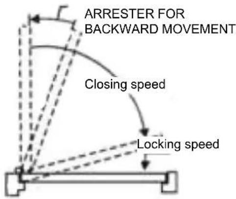
Type of mounting

Installation instructions for fitting door closer, standard installation, opening side
Template for standard installation, opening up to 180°.

• Right-hung door shown
• Left-hung door fitted in opposite way
- Dimensions in mm
• The drawing is not to scale
| OPENING DIMENSION A | |
| TO-120° 110 mm | |
| TO-180° 65 mm |
Installation instructions
- Choose door opening angle and use the above dimensions.
- Mark out 4 holes on the door for the door closer and 2 holes on the frame for the arm bracket. Predrill holes in the door and frame for wood screws or M6 screws.
- Fit the arm bracket and outer arm on the frame with the supplied screws.
- Fit the door closer on the door with the supplied screws. The valve for the closing speed should face towards the hinge side.
- Fit the vertical arm on the upper shaft, at right angles to the door, as shown in the diagram. Fix with the supplied screw and washer, and tighten.
- Adjust the length of the outer arm so that it is at right angles to the frame when fitted on the preloaded vertical arm (see diagram below). Fix the outer arm on the vertical arm with the supplied screw and washer, and tighten.
- Place the cover over the shaft on the underside of the door closer.
- Adjust the closing speed (see Adjusting the door closer).
View from above for standard installation

Installation instructions of door closer, door frame, opening side
Template for installation on lintel, opening up to 180°.

• Left-hung door shown
• Right-hung door fitted in opposite way
- Dimensions in mm
• The drawing is not to scale
| OPENING DIMENSION A | |
| TO-120° 110 mm | |
| TO-180° 80 mm |
Installation instructions
- Choose door opening angle and use the above dimensions.
- Mark out 4 holes on the door for the door closer and 2 holes on the frame for the arm bracket. Predrill holes in the door and frame for wood screws or M6 screws.
- Fit the arm bracket and outer arm on the frame with the supplied screws.
- Fit the door closer on the door with the supplied screws. The valve for the closing speed should face towards the hinge side.
- Fit the vertical arm on the upper shaft, at right angles to the door, as shown in the diagram. Fix with the supplied screw and washer, and tighten.
- Adjust the length of the outer arm so that it is at right angles to the frame when fitted on the preloaded vertical arm (see diagram below). Fix the outer arm on the vertical arm with the supplied screw and washer, and tighten.
- Place the cover over the shaft on the underside of the door closer.
- Adjust the closing speed (see, Adjusting the door closer).
View from above of door frame installation
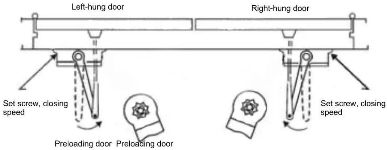
Jula reserves the right to make changes. In the event of problems, please contact our service department. www.jula.com
- Operating Instructions for Door Closer
- SVENSKA 3
- MONTERING....3
- Read the Operating Instructions carefully before use!
- INSTALLATION
- Standard installation of door closer
- Installation of door closer, door frame
- Adjusting the door closer
- Closing cycle
- Installation instructions for fitting door closer, standard installation, opening side
- Installation instructions
- View from above for standard installation
- Installation instructions of door closer, door frame, opening side
- View from above of door frame installation
Brand : Hard Head
Model : 345-202
Category : Door closer