345-203 - Door closer Hard Head - Free user manual and instructions
Find the device manual for free 345-203 Hard Head in PDF.


| Product Type | Door closer |
| Brand | Hard Head |
| Model | 345-203 |
| Material | Steel body with nylon bushings |
| Dimensions (approx.) | 260 x 60 x 80 mm |
| Weight (approx.) | 1.5 kg |
| Mounting Type | Surface mounted (standard arm or parallel arm) |
| Door Handing | Left-hung or right-hung |
| Max Door Opening Angle | 180° |
| Closing Speed Adjustment | Yes, via valve 1 (hex key) |
| Locking Force Adjustment | Yes, via valve 2 (hex key) |
| Opening/Closing Force Adjustment | Yes, via set screw (hex key) |
| Backcheck (Arrester) | Adjustable, prevents door from opening fully into wall |
| Delay Action | Adjustable, slow closing to 70° |
| Included Accessories | Mounting template, screws, hex key, arm bracket |
| Compliance | EN 1154 (standard for door closers) |
| Maintenance | Quarterly: check operation, tighten screws, lubricate joints |
| Safety Warning | Incorrect installation or adjustment can cause personal injury or material damage |
| Repairability | Adjustable valves and replaceable arm parts |
| Use | Interior or exterior doors up to standard weight |
Frequently Asked Questions - 345-203 Hard Head
User questions about 345-203 Hard Head
0 question about this device. Answer the ones you know or ask your own.
Ask a new question about this device
Download the instructions for your Door closer in PDF format for free! Find your manual 345-203 - Hard Head and take your electronic device back in hand. On this page are published all the documents necessary for the use of your device. 345-203 by Hard Head.
USER MANUAL 345-203 Hard Head
Operating Instructions for Door Closer
345-203

SV Bruksanvisning i original
NO Bruksanvisning i original
EN Operating instructions in original
SVENSKA 4
BESKRIVNING 4
Arm....4
Fitted on opening side of the door 30
Mounting 31
INSTALLATION 31
Door closer 32
Adjusting the control valves 32
Closing speed/locking force 32
Adjusting the opening/closing force 33
PARALLEL ARM 34
Fitted on closing side of the door 34
Mounting 35
INSTALLATION 35
Door closer 36
Adjusting the control valves 36
Closing speed/locking force 36
Adjusting the opening/closing force 37
Testing 37
Quarterly maintenance 37
MONTERING
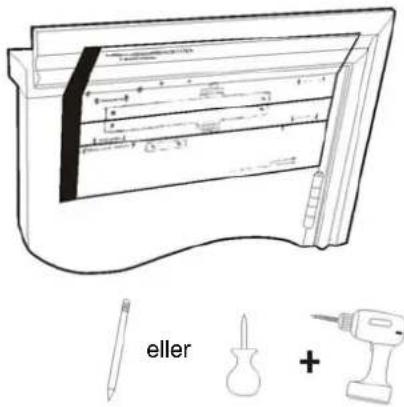
MONTERING
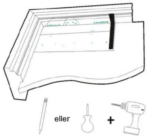
Dörrstängningsvinkel (180°–10°)
- Splint
- Låseskive
- Justerbar ytre arm
- Justeringsskrue A
- Nylonbøssing
- Sekskantskrue M6
- Fjærskive
- Stor skive
- Vertikal arm
Opphenging
VENSTREHENGING
LUKKING MED KLOKKEN

H∅YREHENGING LUKKING MOT KLOKKEN
MONTERING

- Nylonbøssing
- Låseskive
- Parallellarmfeste
- Justerbar ytre arm
- Justeringsskrue A
- Sekskantskrue M6
- Fjærskive
- Stor skive
- Vertikal arm
Opphenging
VENSTREHENGING
LUKKING MED KLOKKEN
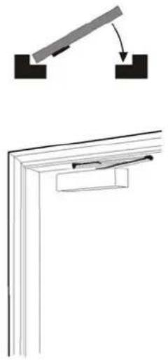
H∅YREHENGING LUKKING
MOT KLOKKEN
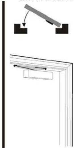
MONTERING
- Monter parallellarmfestet på armen.

Dørlukkingsvinkel (180°–10°)
MONTAŻ


MONTAŻ
Read the Operating Instructions carefully before use!
DESCRIPTION
ARM
Fitted on opening side of the door
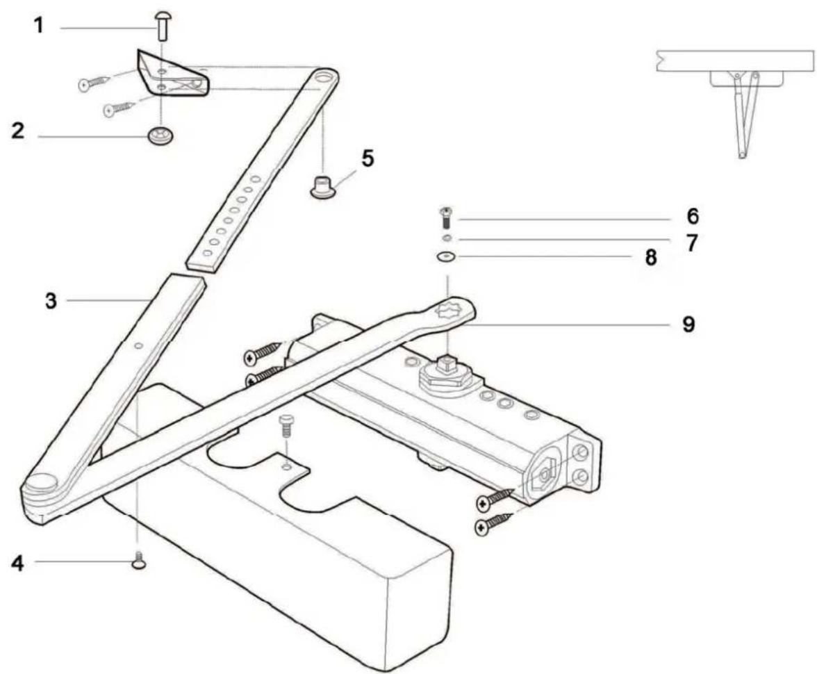
- Cotter
- Lock washer
- Adjustable outer arm
- Set screw A
- Nylon bushing
- Hex screw M6
- Spring washer
- Large washer
- Vertical arm
Mounting
LEFT-HUNG
CLOSING CLOCKWISE

RIGHT-HUNG CLOSING
ANTICLOCKWISE

INSTALLATION

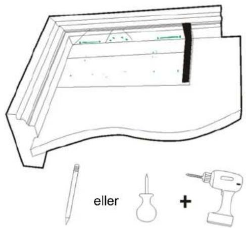
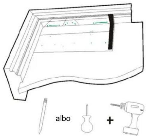
- Align the template A to the hinge edge of the door. Mark out holes for the door closer and arm bracket with a pen, awl or sharp knife. Predrill holes with a 3 mm drill in wooden door/frame. Drill 6 mm holes for M6 screw in metal door/frame.

- Fit the door closer with the supplied screws.


- Fit the bracket on the arm.


- Fit the arm on the mechanism as shown in the loading diagram. Hold the vertical arm in the loading position and fit the arm bracket on the frame. Adjust, if necessary, the outer arm to right angles with the set screw A.
Adjust the control valves on the door closer as shown in step 5.
Step 5
Door closer
IMPORTANT! An incorrectly installed or adjusted door closer can cause personal injury and or/material damage.
Adjusting the control valves
Closing speed/locking force
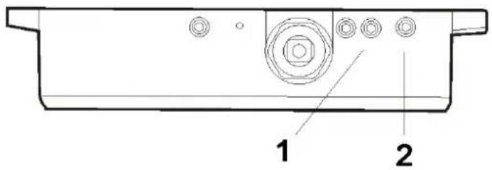
-
Closing speed
-
Locking force
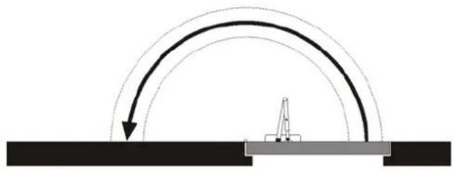
Door opening angle (0°–180°)

Door closing angle (180°–10°)
Adjust the closing speed (valve 1) and locking force (valve 2) with the supplied hex key. Turn the nut clockwise to reduce the closing speed. Do not turn the valves more than two turns anticlockwise from the factory setting, this will cause leakage.
Adjusting the opening/closing force
Adjust the opening/closing force with the supplied hex key.
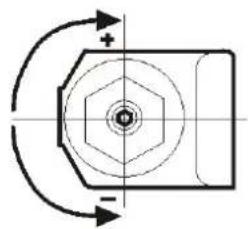
Increase/reduce the force by turning the set screw in the direction shown in the diagram.
PARALLEL ARM
Fitted on closing side of the door
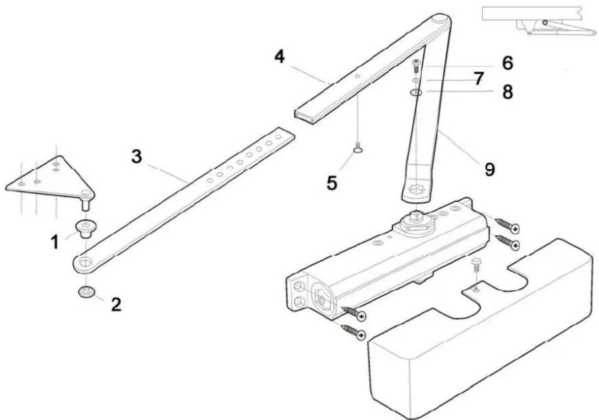
- Nylon bushing
- Lock washer
- Parallel arm bracket
- Adjustable outer arm
- Set screw A
- Hex screw M6
- Spring washer
- Large washer
- Vertical arm
Mounting

INSTALLATION
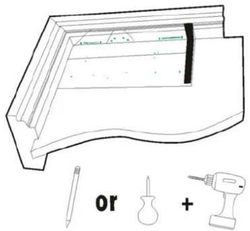
- Align the template B to the hinge edge of the door. Mark out holes with a pen, awl or sharp knife. Predrill holes with a 3 mm drill in wooden door/frame. Drill 6 mm holes for M6 screw in metal door/frame.

- Fit the door closer with the supplied screws.

- Fit the parallel arm bracket on the arm.

- Preload the door closer by turning the shaft on the underside of the door closer about 45° to the hinge edge on the door. Remove set screw A and fix the parallel arm bracket. Adjust the outer arm to the correct angles and replace screw A.
Adjust the control valves on the door closer as shown in step 5.
Door closer
IMPORTANT! An incorrectly installed or adjusted door closer can cause personal injury and or/material damage.
Step 5
Adjusting the control valves
Closing speed/locking force

- Closing speed
- Locking force
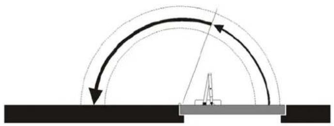
Door opening angle (0°–180°)

Door closing angle (180°–10°)
Adjust the closing speed (valve 1) and locking force (valve 2) with the supplied hex key. Turn the nut clockwise to reduce the closing speed. Do not turn the valves more than two turns anticlockwise from the factory setting, this will cause leakage.
Adjusting the opening/closing force
Adjust the opening/closing force with the supplied hex key.

Increase/reduce the force by turning the set screw in the direction shown in the diagram.
The arrester for backward movement prevents the door opening all the way up to the wall. Increase the arresting force by turning the valve clockwise with the supplied hex key. Do not completely close the valve. Do not use this valve if a delay action is used.
A delay action can only be used if the arrester for backward movement is not used. The delay action means that the door moves slowly to 70° . Increase the delay action by turning the valve clockwise. Do not completely close the valve.
Testing
- Open the door completely and release. The door should close all the way to the frame and lock.
- Open the door and allow the lock cylinder to rest against the lock plate. The door should lock when you release it.
If the door does not close it may be necessary to increase the closing force, or adjust the alignment of the door in the frame.
Quarterly maintenance
Check that the door closes properly and that all screw unions are tightened. Lubricate the door closer joints and door hinges regularly with a thin oil.
Jula reserves the right to make changes. In the event of problems, please contact our service department. www.jula.com
- OPERATING INSTRUCTIONS FOR DOOR CLOSER
- SVENSKA 4
- BESKRIVNING 4
- MONTERING
- OPPHENGING
- MONTAŻ
- READ THE OPERATING INSTRUCTIONS CAREFULLY BEFORE USE
- DESCRIPTION
- ARM
- FITTED ON OPENING SIDE OF THE DOOR
- MOUNTING
- INSTALLATION
- DOOR CLOSER
- ADJUSTING THE CONTROL VALVES
- CLOSING SPEED/LOCKING FORCE
- ADJUSTING THE OPENING/CLOSING FORCE
- PARALLEL ARM
- FITTED ON CLOSING SIDE OF THE DOOR
- TESTING
- QUARTERLY MAINTENANCE
Brand : Hard Head
Model : 345-203
Category : Door closer