
PA 6500 - Mètre PCE Instruments - Free user manual and instructions
Find the device manual for free PA 6500 PCE Instruments in PDF.


| Product Type | Power analyzer (3-phase) |
| Model | PCE-PA 6500 |
| Dimensions (W x H x D) | 123 x 96 x 36 mm |
| Weight | Approx. 202 g (without accessories) |
| Power Supply | 100 ... 240 V AC, 50/60 Hz via L1 |
| Power Consumption | Max. 12.0 W, typical 1.5 W |
| Measurement Functions | Voltage, current, active power, apparent power, reactive power |
| Measurement Uncertainty | Voltage: ±1%, Current: ±1%, Power: ±1% |
| Sampling Rate | Up to 26,000 measurements/s |
| Data Buffer | Separate phases: 22,000 records; Summarized: 38,000 records |
| Communication | WiFi (802.11 b/g/n), Bluetooth BLE (via app) |
| Data Storage | Internal 8 MB flash memory (CSV), optional SD card |
| Display | None (web interface or app) |
| Operating Conditions | -5 °C to 40 °C, 80% RH, max. 2000 m altitude |
| Overvoltage Category | CAT III 300 V |
| Protection Class | IP40 |
| Internal Fuse | 1000 V, 250 mA, FF (ultra-fast), breaking capacity 100 kA |
| Compatible Sensors | Foldable CT (0-80 A AC), Rogowski coils (2-20,000 A AC) |
| Delivery Contents | Meter, 4 test leads, 3 CT/Rogowski coils, 3 magnetic adaptors, crocodile clip, manual, carrying case |
| Maintenance | Clean with damp cloth, pH-neutral cleaner; no abrasives |
| Safety | Use only with CAT III 300 V accessories; observe voltage limits; only qualified personnel |
| Reparability | Fuse replaceable; battery (LIR2032) replaceable; other repairs by PCE Instruments |
Frequently Asked Questions - PA 6500 PCE Instruments
User questions about PA 6500 PCE Instruments
0 question about this device. Answer the ones you know or ask your own.
Ask a new question about this device
Download the instructions for your Mètre in PDF format for free! Find your manual PA 6500 - PCE Instruments and take your electronic device back in hand. On this page are published all the documents necessary for the use of your device. PA 6500 by PCE Instruments.
USER MANUAL PA 6500 PCE Instruments
User manuals in various languages (français, italiano, español, português, nederlands, türk, polski, русский, 中文) can be found by using our product search on: www.pce-instruments.com
2 Specifications....21
2.1 Technical specifications.... 21
2.2 Current transformers / Rogowski coils 21
2.3 Delivery contents 22
3 System description 22
3.1 Device....23
3.2 Status LEDs....24
3.3 Function keys....25
3.4 Site requirements.... 25
3.5 Connection to power supply 25
3.6 Internal fuse....26
3.7 Residual current operated circuit breaker 26
4 Connection of the current transformers and test leads......27
4.1 Three-phase measurement 27
4.2 Measuring single-phase loads....27
5 Operation 28
5.1 General information on the PCE-PA 6500 WiFi....28
5.2 Initial WiFi configuration.... 28
5.3 Access via AP (internal access point) 29
5.4 Access via WiFi (if internet connectivity has been configured) 29
5.5 Access via app....29
5.6 Admin and user login 29
6 Troubleshooting....30
6.1 Red LED is flashing (general error) 30
6.2 Negative active power readings.... 31
6.3 Unrealistic power readings 31
6.4 Unrealistic voltage reading 31
6.5 No function (all LEDs stay off) 31
7 Contact....32
8 Disposal 32
6.1.1 Filesystem is full
6.1.2 Filesystem is damaged
6.1.3 Empty Battery or RTC defect
6.1.4 EEPROM chip defect
6.1.5 Sensor not calibrated
6.1.6 Unknown error or HW defect
Please read this manual carefully and completely before you use the device for the first time. The device may only be used by qualified personnel and repaired by PCE Instruments personnel. Damage or injuries caused by non-observance of the manual are excluded from our liability and not covered by our warranty.
- The device must only be used as described in this instruction manual. If used otherwise, this can cause dangerous situations for the user and damage to the meter.
- The instrument may only be used if the environmental conditions (temperature, relative humidity, ...) are within the ranges stated in the technical specifications. Do not expose the device to extreme temperatures, direct sunlight, extreme humidity or moisture.
- Do not expose the device to shocks or strong vibrations.
• The case should only be opened by qualified PCE Instruments personnel.
- Never use the instrument when your hands are wet.
- You must not make any technical changes to the device.
- The appliance should only be cleaned with a damp cloth. Use only pH-neutral cleaner, no abrasives or solvents.
• The device must only be used with accessories from PCF Instruments or equivalent.
- Before each use, inspect the case for visible damage. If any damage is visible, do not use the device.
- Do not use the instrument in explosive atmospheres.
- The measurement range as stated in the specifications must not be exceeded under any circumstances.
- Non-observance of the safety notes can cause damage to the device and injuries to the user.
We do not assume liability for printing errors or any other mistakes in this manual.
We expressly point to our general guarantee terms which can be found in our general terms of business.
Safety symbols
Safety-related instructions the non-observance of which can cause damage to the device or personal injury carry a safety symbol.
| Symbol | Designation / description | |
 | Warning: electrical voltageNon-observance can cause electric shock. | |
 | General warning signNon-observance can cause damage to the device and injuries to the user. | |
The PCE-PA 6500 may only be connected by a specialist. Consult a professional if you have any doubt about operation, safety or connection of the device. The safety of the system in which the meter is integrated, is under the responsibility of the installer.
Measuring instruments and accessories are not toys and must be kept out of children's reach.

Use only with accessories certified for over-voltage category III, 300V. The use of fully insulated accessories, guarded against accidental contact, is absolutely necessary for connection to the neutral conductor! If the neutral conductor is disconnected from the supply during operation, the full supply voltage of phase 1 will be on the connector of the neutral conductor. The use of a magnetic probe tip or other not fully insulated accessories on the neutral conductor is highly dangerous!
In commercial institutions, the accident prevention regulations of the professional association for electrical systems and equipment must be observed.
The voltage between the three phases and the neutral conductor must not exceed 264 V \~. The voltage between the three phases must not exceed 440 V \~.
The voltage at the current inputs must not exceed 1 V \~.
Be especially careful when connecting the test leads. Touching electric lines is dangerous to life!
Before each use of the meter and all peripheral components (test leads, test adaptors, power converters) should be checked for damage. Do not attempt any measurements if the protecting insulation is defective (torn or demolished).
Do not use the meter immediately prior to, during or after a thunderstorm (lightning / over-voltage). Make sure that your hands, shoes, clothing, the floor, switches and switching components are dry during the measurement.
Avoid operation in the immediate vicinity of strong magnetic or electromagnetic fields and transmitting antennas or RF generators because the measured values could be falsified.
The device is only to be installed in interior rooms with max. pollution degree of 2.
Never immediately turn on the meter when it has been moved from a cold to a warm room. The resulting condensation could destroy the device under certain circumstances. Allow the meter to reach room temperature slowly in switched off condition.
If it is suspected that safe operation of the instrument is no longer possible, the device must be taken out of service and secured against inadvertent operation. It can be assumed that safe operation is no longer possible if:
• the device is visibly damaged
• the device no longer works
- it was stored under unfavourable conditions for a longer period
• stress has been caused by transport
Exercise extreme caution when fitting the current transformers and test leads. There is a risk of electric shock! Use of protective equipment (e.g.: insulating gloves, shoes, goggles, etc.) to prevent electric shocks and arcs is strongly advised.
In schools and training centres, hobby and DIY workshops, handling of measuring instruments must be supervised by trained personnel.
If possible, try to avoid working alone so that assistance can be provided in case of emergency.
2 Specifications
2.1 Technical specifications
| Specifications | |
| Input level for current transformers | ±0.125 V ... ±0.5 V |
| Power supply for active current measurement (Rogowski coils) | 5 V DC, max. 100 mA |
| Max. input voltage | 240 V to neutral, 400 V phase to phase |
| Measurement uncertainty | voltage: +/- 1%current: +/- 1%active power: +/- 1%apparent power: +/- 1%reactive power +/- 1% |
| Sampling rate | up to 26,000 measurements/s |
| Data buffer | separate phases: 22,000 records summarised phases: 38,000 records |
| General | |
| Power supply | 100 ... 240 V AC 50/60 Hz via L1 |
| Power consumption (maximum/typical) | 12.0 W / 1.5 W |
| Operating conditions | -5 °C ... 40 °C; 80 % RHmax. altitude 2000mdust-free and dry |
| Weight (without test leads and magnetic adaptor) | aaprox. 202 g |
| Dimensions (W x H x D) | 123 x 96 x 36 mm |
| Fuse | 1000 V, 250 mA, FF (ultraflink) |
| max. Shutdown capacity | 100 kA |
| Overvoltage category | CAT III 300 V |
| Protection class | IP40 |
2.2 Current transformers / Rogowski coils
| Sensor type / model | PCE-PA 6500-R11 | PCE-PA 6500-F50 | PCE-PA 6500-F150 |
| Image | 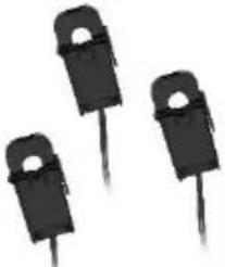 |  | 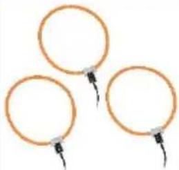 |
| Type of current transformer | Foldable current transformer | Rogowski coil | Rogowski coil |
| Inner diameter | 11 mm | 50 mm | 150 mm |
| Max. cable diameter | 10 mm | 49 mm | 149 mm |
| Measurement range | 0 ... 80 A AC | 2 ... 20.000 A AC | 2 ... 9500 A AC |
2.3 Delivery contents
1 x meter PCE-PA 6500-xxxx
4 x test leads (blue, brown, black, gray) 2 m
3 x current transformers or Rogowski coils (depending on the model)
3 x magnetic measuring adaptors 6.6 mm
1 x blue crocodile clip
1 x user manual
1 x carrying case
3 System description
The PCE-PA 6500 measures current and voltage values by means of the connected current transformers and test leads. The consumed active, apparent and reactive power is calculated and transmitted every second to the measuring platform [=> 9] via WiFi. There, the data is saved historically and can be analysed, combined, averaged and graphically displayed.
Alternatively (in the absence of an internet connection), the data will be saved to the built-in 8 MB flash memory as a CSV file for later processing. A separate SD card adaptor is available for purchase to make measurements of a duration of up to one year at one-second precision possible.
Additionally, you have the possibility to periodically send the CSV files by email, to upload them to a server via FTP or transfer them to the measuring platform after completing a measurement. The interaction with the meter takes place predominantly via WiFi and web browser or via the app (BLE).
3.1 Device
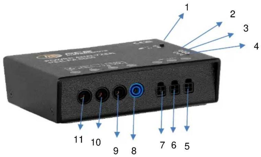
- Key to activate access point / factory reset
- Power LED
- WiFi LED
- Error LED
- Current input for phase 1
- Current input for phase 2
- Current input for phase 3
- Test lead for neutral conductor
- Voltage input for phase 1 (also for power supply of the meter)
- Voltage input for phase 2
- Voltage input for phase 3
3.2 Status LEDs
| Power LED (green) (2) | |
| Off | Not connected to power (neutral conductor and phase 1) or internal fuse defective |
| Fast flashing(3 x/s) | Initial configuration needed (no admin password has been set yet) |
| On, short breaks, every two seconds | Status: OK, normal operation |
| WiFi LED (yellow) (3) | |
| Off | WiFi, access point inactive |
| On | Access point is active |
| Short flashing(e.g. 1 x/s) | WiFi connection active, data is successfully transmitted. The frequency of the flashes shows the frequency of data transmission. |
| Fast flashing(3 x/s) | No WiFi connection possible (wrong SSID, password or the chosen WiFi network cannot be reached) |
| Slow flashing(1 x/s) | WiFi connection successful but no connection to telemetry server possible (wrong server URL, password, port, etc.) |
| Fast flickering | Release key to reset to factory settings |
| Error LED (red) (4) | |
| Off | No error, normal operation |
| Fast flashing(3 x/s) | General error |
| Slow flashing(1 x/s) | Warning. For details see web interface.Or (temporary): firmware is being updated via web download. |
| Fast flickering | Configuration will be deleted if key is now released. |
3.3 Function keys
| WiFi/reset key (1) | |
| Short press (approx. 1 s) | Start or stop internal access point (AP).When the AP is active, the Bluetooth® wireless technology protocol is disabled! |
| Hold for approx. 8 s | Factory reset will be performed if the key is released while the yellow LED is flickering quickly. Device will reboot.Counter values and CSV files will not be changed!The following settings will be reset:device_name = PCE-PA 6xxxadmin_name =admin_pass =ap_enabled = 0ap_mode = 0ap_addr = 10.1.1.1update_enabled = 1update_auto = 1update_url =update.PCE-PA.de/update.phpupdate_interval = 24mdns_enabled = 1webserver_enabled = 1websocket_enabled = 1 |
| Hold for approx. 15 s | The complete configuration will be deleted if the key is released while the red LED is flickering quickly.The telemetry token, the kWh counters and the CSV files will not be deleted! |
3.4 Site requirements
This instrument has been designed for use indoors. Operation is safe under the following ambient conditions: max. 2000 m above sea level, ambient temperature of 5^ C to 40^ C, maximum relative humidity of 80 %, max. variation of the supply voltage of +/- 10%. The installation site should be clean and free of dust (max. pollution degree 2).
3.5 Connection to power supply
The power supply of the meter is established using test leads. It is recommended to always connect the neutral conductor first and remove last.
3.6 Internal fuse
The internal power supply is protected by a fuse. Should the device be connected to excessive voltage, the fuse will be triggered and must be replaced.
To replace the fuse, first make sure to disconnect the meter from the power supply and all external accessories and cables from the device. Remove the screws of the housing. Replace the fuse with one of the same type that is: 1000 V, 250 mA, FF (ultraflink), IR = 100kA.
3.7 Residual current operated circuit breaker
The cables for phase 1 and for the neutral conductor provide current to the integrated power supply. These connections must be made on the same side of the residual current operated circuit breaker, otherwise the same will be activated!
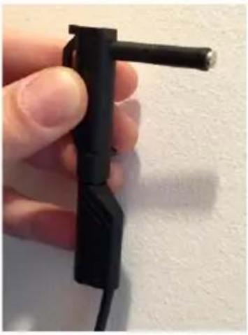 | 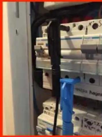 | 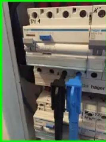 |
| Magnetic test tip | wrong | correct |
4 Connection of the current transformers and test leads
In order to obtain correct power values, the test leads and current transformers must always be connected to the same phase. E.g. the test lead for phase 1 is connected to the same line as the current transformer for phase 1.

The test lead for the neutral conductor must always be connected to the neutral conductor, never to one of the three phases!

Please follow the safety instructions!
4.1 Three-phase measurement
In three-phase operation, the current transformers and test leads are connected to the phases 1, 2 and 3 of a single, three-phase load (or system) and to the neutral conductor.
4.2 Measuring single-phase loads
If one or multiple individual, single-phase loads are to be measured, the current transformers for the phases 1 (5), 2 (6) and 3 (7) can be connected to any location in the fuse box to each of the three phases. The three test leads have to be attached to the corresponding phases.

Please follow the safety instructions!
It is also possible to measure only one single-phase load. In order to ensure the internal power supply of the meter, test lead A and the associated current transformer A are to be used.
5 Operation
When the initial configuration is done, the PCE-PA 6500 begins to record measurement data after only about 10 seconds. Currently, the PCE-PA 6500 can only be operated offline.
- Offline-operation (recording the measurement data in the internal flash memory as a CSV file) Select this operation mode if no WiFi network is available or transfer of data using WiFi is not desired or useful.
5.1 General information on the PCE-PA 6500 WiFi
All PCE-PA 6500 meters have the option of using two WiFi connections simultaneously. To differentiate between these, an access point (AP) is used. This network is activated by the device itself for ten minutes after the key is pressed and can be deactivated again by pressing the key again.
As this network is not encrypted, its use is only recommended for initial configuration and possibly for sporadic retrieval of measured values or CSV files. Permanent operation of the AP is not intended or recommended.
The second WiFi connection of the meter is used to establish a permanent connection to an existing WiFi network. Ideally, communication with the meter should take place via this connection.
5.2 Initial WiFi configuration
To configure or commission the device, it is only necessary to connect the power supply via the neutral conductor and phase 1. The device should activate the green LED after a few seconds. This then indicates either normal operation or, if necessary, the initial configuration.
If the device has been reset to factory settings, an initial configuration must always be made. This is indicated by the green LED flashing rapidly. If an unconfigured device does not have an internet connection set, the meter is accessed via an access point.
The access point (AP) is switched on by pressing the key (1) once and its activity is indicated by the yellow WiFi LED (3) glowing continuously. As soon as you have connected to the WiFi of the PCE-PA 6500 via your PC, you can access the device via the browser.
The name of this WiFi corresponds to the device ID printed on the type plate.
As soon as the initial configuration has been carried out and a user name and password have been assigned for the admin account, all functions of the device are available.
- Activate access point by pressing and releasing the key
- Select PCE-PA 6500-xxxx WiFi
- Open initial configuration in browser: http://10.1.1.1
- Admin user name and password as well as optional WiFi are configured. ==> Save & reboot.
5.3 Access via AP (internal access point)
If no Wi-Fi network is available or the PCE-PA 6500 has not been configured accordingly, the device can be accessed via the integrated access point. You switch this on by pressing the key (1) for a period of ten minutes. Activity is indicated by the yellow Wi-Fi LED (2) glowing continuously. You are directly connected to the Wi-Fi of the meter. The name of this Wi-Fi corresponds to the device ID printed on the front of the device. Access via web browser is via the IP address: http://10.1.1.1
5.4 Access via WiFi (if internet connectivity has been configured)
If you have already configured an internet connection for your meter and are in the same (Wi-Fi) network as your laptop or mobile device, you can access the device via the mDNS name. This is made up of the device ID and the postfix .local.
E.g.: http://pce-pa-6500-a4ce8d.local or http://cooling_chamber_4.local or http://house_connection.local
5.5 Access via app
The PCE-PA 6500 provides the ability to communicate via Bluetooth® in addition to Wi-Fi. To use this communication method, please use the PCE-PA app which is available for Android.
Please be aware that BLE functionality is turned off while the access point (AP) is active!
5.6 Admin and user login
The device offers two different access options:
The admin account has read and write access. The user account only has read access.
The ‘User’ access offers all options for displaying and retrieving data and counter readings but it is not possible to change any functionality, values or settings. This also applies to the range of commands available on the command line. This account can be used, for example, to grant an employee access to the measurement data without running the risk of settings being changed or data being accidentally deleted.
To activate these user accounts, a user name must be entered. The name of the account and the password can be freely chosen.
6 Troubleshooting
6.1 Red LED is flashing (general error)
If the red LED flashes rapidly (3x per second), the PCE-PA 6500 shows a general error.
Errors are shown in a big red box, right after logging into the web interface of the PCE-PA 6500.

The different errors are described here:
6.1.1 Filesystem is full
The internal memory of the PCE-PA 6500 is full. No more data can be written.
Please delete some files to free space in the file system. The error message will disappear as soon as space is available again and recording will resume.
6.1.2 Filesystem is damaged
The internal memory of the PCE-PA 6500 has errors and cannot be written to anymore.
Please restart the device. Should the error persist, you have to format the file system.
6.1.3 Empty battery or RTC defect
The internal clock of the PCE-PA 6500 could not be set correctly after starting. There are several possible reasons for this:
- If the meter has not been used for some time, the built-in rechargeable battery may be flat, causing a loss of the set time. You can charge the battery during operation and it should have sufficient power after 24 hours to run the integrated real-time clock for many weeks.
- When the PCE-PA 6500 is connected to the internet, the integrated clock is automatically synchronised. Otherwise, you can synchronise the time with your web browser, via the "Clock" page. Disconnect the PCE-PA 6500 from voltage for a short time to see if the error message disappears after a restart.
- To test the integrated rechargeable battery, charge it for an hour and then disconnect the meter from the supply voltage for some hours. If the above-mentioned error persists, the battery must be replaced. Make sure to use the correct type which is LIR2032. This is a Li-Ion rechargeable battery! Do NOT replace by the more common CR2032 as the charging voltage will destroy these batteries after a short time.
6.1.4 EEPROM chip defect
The built-in non-volatile memory is defective. Please send us your device for repair.
6.1.5 Sensor not calibrated
The built in energy measurement chip has lost its calibration data. Future measurements might be unprecise or erroneous. Please send us your device for re-calibration.
6.1.6 Unknown error or HW defect
Please contact PCE Instruments.
6.2 Negative active power readings
- Check the current transformers for correct installation (arrow/label in direction of current flow.)
• If applicable, turn the affected current transformers or Rogowski coils by 180°. - Invert the connection via Setup => Advanced => Current Sensor.
6.3 Unrealistic power readings
If the power readings are considerably different from what you expected, it is very likely that the test leads and current transformers are not connected to the same phase. This normally causes a high deviation between apparent and active power and a power factor of <0.6. In this case, please check if the phases have been selected correctly.
6.4 Unrealistic voltage reading
Check the test leads (magnetic test tips) for bad connections.
6.5 No function (all LEDs stay off)
- Check for the correct power supply of the device. Only the voltage inputs for the neutral conductor and phase 1 are important.
- If the power supply is given and in the correct range, it is possible that the internal fuse was triggered. This protects the meter from dangerous overvoltage and can happen if, for example, a phase has accidentally been connected instead of the neutral conductor and thus the device was powered with 400 V instead of the expected 240 V.
- The fuse is a special super-fast multimeter fuse with a highly enhanced breaking capacity of at least 30 kA.
7 Contact
If you have any questions, suggestions or technical problems, please do not hesitate to contact us. You will find the relevant contact information at the end of this user manual.
8 Disposal
For the disposal of batteries in the EU, the 2006/66/EC directive of the European Parliament applies. Due to the contained pollutants, batteries must not be disposed of as household waste. They must be given to collection points designed for that purpose.
In order to comply with the EU directive 2012/19/EU we take our devices back. We either re-use them or give them to a recycling company which disposes of the devices in line with law.
For countries outside the EU, batteries and devices should be disposed of in accordance with your local waste regulations.
If you have any questions, please contact PCE Instruments.


PCE Instruments contact information
Germany France Spain
PCE Deutschland GmbH PCE Instruments France EURL PCE Ibérica S.L.
Im Langel 26 23, rue de Strasbourg Calle Mula, 8
D-59872 Meschede 67250 Soultz-Sous-Forets 02500 Tobarra (Albacete)
Chester Rd, Old Trafford
Manchester M32 0RS
United Kingdom
Tel: +44 (0) 161 464902 0
Fax: +44 (0) 161 464902 9
info@pce-instruments.co.uk
www.pce-instruments.com/english
Italy
PCE Italia s.r.l.
Via Pesciatina 878 / B-Interno 6
55010 Loc. Gragnano Pehlivan Sok. No.6/C
Capannori (Lucca)
Italia
www.pce-instruments.com/turkish
The Netherlands
PCE Brookhuis B.V.
Institutenweg 15
7521 PH Enschede
Nederland
Telefoon: +31 (0)53 737 01 92
info@pcebenelux.nl
www.pce-instruments.com/dutch Fax: +1 (561) 320-9176
info@pce-americas.com
www.pce-instruments.com/us
United States of America
PCE Americas Inc.
1201 Jupiter Park Drive, Suite 8
Jupiter / Palm Beach
33458 FL
USA
Tel: +1 (561) 320-9162
Denmark
PCE Instruments Denmark ApS
Birk Centerpark 40
7400 Herning
Denmark
Specifications are subject to change without notice.


- Filesystem is full
- Filesystem is damaged
- Empty Battery or RTC defect
- EEPROM chip defect
- Sensor not calibrated
- Unknown error or HW defect
- Safety symbols
- Specifications
- Delivery contents
- System description
- Device
- Status LEDs
- Function keys
- Site requirements
- Connection to power supply
- Internal fuse
- Residual current operated circuit breaker
- Connection of the current transformers and test leads
- Three-phase measurement
- Measuring single-phase loads
- Operation
- General information on the PCE-PA 6500 WiFi
- Initial WiFi configuration
- Access via AP (internal access point)
- Access via WiFi (if internet connectivity has been configured)
- Access via app
- Admin and user login
- Troubleshooting
- Red LED is flashing (general error)
- Negative active power readings
- Unrealistic power readings
- Unrealistic voltage reading
- No function (all LEDs stay off)
- Contact
- Disposal
- PCE Instruments contact information
- Germany France Spain
- Italy
- The Netherlands
- United States of America
- Denmark
Brand : PCE Instruments
Model : PA 6500
Category : Mètre