
TDS 200 M - Mètre PCE Instruments - Free user manual and instructions
Find the device manual for free TDS 200 M PCE Instruments in PDF.


| Product Type | Ultrasonic Flowmeter (Handheld) |
| Brand | PCE Instruments |
| Model | TDS 200 M |
| Measured Parameters | Flow velocity, volume flow, volume (temperature, heat output, heat quantity on PCE-TDS 200+ models) |
| Flow Measurement Range | ±32 m/s |
| Resolution (Flow) | 0.001 m/s |
| Accuracy (Flow) | DN ≥50 mm: ±1.5% of rdg. for velocity >0.3 m/s; DN <50 mm: ±3.5% of rdg. |
| Repeatability | ±0.5% of rdg. |
| Sensor Type | PCE-TDS 200 M (pair) for pipe DN 50…700 (57…720 mm) |
| Pipe Diameter Range | DN 50…700 (57…720 mm) |
| Liquid Temperature | -30…+160 °C (-22…+320 °F) |
| Display | 2.8" LCD |
| Data Logger | 32 GB memory, up to 100 records, max 100,000 data points per record |
| Interface | USB (for online measurement and data readout) |
| Power Supply | Internal rechargeable LiPo (3.7 V, 2500 mAh) or external USB 5 VDC, 500 mA |
| Battery Life | Approx. 8…10 hours (depending on display brightness) |
| Protection Class | IP 52 |
| Operating Conditions | Temperature: -20…+65 °C; Humidity: 10…95% RH, non-condensing |
| Sensor Dimensions (M sensor) | 70 x 40 x 40 mm (2.8 x 1.6 x 1.6 in) |
| Sensor Weight (M sensor) | 260 g (0.57 lb) |
| Menu Languages | English, German, French, Spanish, Italian, Dutch, Portuguese, Turkish, Polish, Russian, Chinese, Danish, Japanese |
| Delivery Contents | 1x flow meter, 2x M sensors, 2x 5 m cable, 2x Velcro cable tie, 1x mains adaptor, 1x USB-C cable, 1x coupling gel, 1x tape measure, 1x carrying case, 1x user manual |
| Cleaning | Use a damp cloth with pH-neutral cleaner; no abrasives or solvents |
| Safety | Do not use in explosive atmospheres; do not exceed measurement range; only use qualified personnel for repair |
Frequently Asked Questions - TDS 200 M PCE Instruments
User questions about TDS 200 M PCE Instruments
0 question about this device. Answer the ones you know or ask your own.
Ask a new question about this device
Download the instructions for your Mètre in PDF format for free! Find your manual TDS 200 M - PCE Instruments and take your electronic device back in hand. On this page are published all the documents necessary for the use of your device. TDS 200 M by PCE Instruments.
USER MANUAL TDS 200 M PCE Instruments
User manuals in various languages (français, italiano, español, português, nederlands, türk, polski, русский, 中文) can be found by using our product search on: www.pce-instruments.com
3.1 Technical specifications ....30
3.2 Delivery contents....31
3.3 Models of the series 32
3.4 Optional accessories....32
4 System description 33
4.1 Device....33
4.2 Function keys....34
5 Getting started 35
5.1 Power supply 35
5.2 Preparation 35
6 Menu 36
6.1 Measurement....36
6.2 Settings overview 44
6.3 Data logger 44
6.4 User menu 45
6.5 Setting....46
6.6 Calibration....46
6.7 Manual....47
6.8 Info....47
7 Measurement.... 48
7.1 Measuring principle and measuring methods 48
7.2 Getting started....50
7.3 Procedure 51
7.4 Measurement display....53
8 Service 54
8.1 Measurement....54
8.2 Support request....55
8.3 Firmwareupdate 55
8.4 Reset language....55
9 Contact....56
10 Disposal 56
natural_image
Simple red battery icon on black background (no text or symbols)W-Methode
flowchart
graph TD
    A["①"] --> B["②"]
    B --> C["③"]
    C --> D["④"]
    style A fill:#f9f,stroke:#333
    style B fill:#ccf,stroke:#333
    style C fill:#cfc,stroke:#333
    style D fill:#fcc,stroke:#333
line
| Time (s) | Flussgeschwindigkeit (m/s) | | -------- | -------------------------- | | 0 | 0.0 | | 1 | 0.0 | | 2 | 0.0 | | 3 | 0.0 | | 4 | 0.0 | | 5 | 0.0 | | 6 | 0.0 | | 7 | 0.0 | | 8 | 0.0 | | 9 | 0.0 | | 10 | 0.0 | | 11 | 0.0 | | 12 | 0.0 | | 13 | 0.0 | | 14 | 0.0 | | 15 | 0.0 | | 16 | 0.0 | | 17 | 0.0 | | 18 | 0.0 | | 19 | 0.0 | | 20 | 0.0 | | 21 | 0.0 | | 22 | 0.0 | | 23 | 0.0 | | 24 | 0.0 | | 25 | 0.0 | | 26 | 0.0 | | 27 | 0.0 | | 28 | 0.0 | | 29 | 0.0 | | 30 | 0.0 | | 31 | 0.0 | | 32 | 0.0 | | 33 | 0.0 | | 34 | 0.0 | | 35 | 0.0 | | 36 | 0.0 | | 37 | 0.0 | | 38 | 0.0 | | 39 | 0.0 | | 40 | 0.0 | | 41 | 0.0 | | 42 | 0.0 | | 43 | 0.0 | | 44 | 0.0 | | 45 | 0.0 | | 46 | 0.0 | | 47 | 0.0 | | 48 | 0.0 | | 49 | 0.0 | | 50 | 0.0 | | 51 | 0.0 | | 52 | 0.0 | | 53 | 0.0 | | 54 | 0.0 | | 55 | 0.0 | | 56 | 0.0 | | 57 | 0.0 | | 58 | 0.0 | | 59 | 0.0 | | 60 | 0.0 | | 61 | 0.0 | | 62 | 0.0 | | 63 | 0.0 | | 64 | 0.0 | | 65 | 0.0 | | 66 | 0.0 | | 67 | 0.0 | | 68 | 0.0 | | 69 | 0.0 | | 70 | 0.0 | | 71 | 0.0 | | 72 | 0.0 | | 73 | 0.0 | | 74 | 0.0 | | 75 | 0.0 | | 76 | 0.0 | | 77 | 0.0 | | 78 | 0.0 | | 79 | 0.0 | | 80 | 0.0 | | 81 | 0.0 | | 82 | 0.0 | | 83 | 0.0 | | 84 | 0.0 | | 85 | 0.0 | | 86 | 0.0 | | 87 | 0.0 | | 88 | 0.0 | | 89 | 0.0 | | 90 | 0.0 | | 91 | 0.0 | | 92 | 0.0 | | 93 | 0.0 | | 94 | 0.0 | | 95 | 0.0 | | 96 | 0.0 | | 97 | 0.0 | | 98 | 0.0 | | 99 | 0.0 | | Note: The data is extracted from the image and displayed on the screen.Please read this manual carefully and completely before you use the device for the first time. The device may only be used by qualified personnel and repaired by PCE Instruments personnel. Damage or injuries caused by non-observance of the manual are excluded from our liability and not covered by our warranty.
- The device must only be used as described in this instruction manual. If used otherwise, this can cause dangerous situations for the user and damage to the meter.
- The instrument may only be used if the environmental conditions (temperature, relative humidity, ...) are within the ranges stated in the technical specifications. Do not expose the device to extreme temperatures, direct sunlight, extreme humidity or moisture.
- Do not expose the device to shocks or strong vibrations.
• The case should only be opened by qualified PCE Instruments personnel. - Never use the instrument when your hands are wet.
- You must not make any technical changes to the device.
- The appliance should only be cleaned with a damp cloth. Use only pH-neutral cleaner, no abrasives or solvents.
• The device must only be used with accessories from PCE Instruments or equivalent. - Before each use, inspect the case for visible damage. If any damage is visible, do not use the device.
- Do not use the instrument in explosive atmospheres.
- The measurement range as stated in the specifications must not be exceeded under any circumstances.
- Non-observance of the safety notes can cause damage to the device and injuries to the user.
We do not assume liability for printing errors or any other mistakes in this manual.
We expressly point to our general guarantee terms which can be found in our general terms of business.
2 Introduction
The ultrasonic flowmeter precisely measures flow velocity, volume flow and heat quantity in pipe systems with high accuracy and reproducibility. An installation aid graphically indicates the correct sensor position and signal quality. The measured values are recorded on an internal memory and can be exported via software as .csv or PDF and displayed live. For heat quantity measurement, two thermocouples are used to calculate the heat quantity based on the temperature difference and the flow rate. The device can optionally be equipped with an ISO or DAkkS calibration certificate. The ultrasonic flowmeter is subject to a 100 % factory test to ensure the highest quality standards and measuring accuracy.
3 Specifications
3.1 Technical specifications
Handheld device
| Model | PCE-TDS 200 Series |
| Measured parameters | PCE-TDS 200:flow velocity, volume flow and volumePCE-TDS 200+:flow velocity, volume flow, volume, temperature, heat output and heat quantity |
| Flow measurement | |
| Measurement range | ±32 m/s |
| Resolution | 0.001 m/s |
| Accuracy | DN ≥50 mm / approx. 2 in: ±1.5 % of rdg. for velocities >0.3 m/sDN <50 mm / approx. 2 in: ±3.5 % of rdg. for velocities >0.3 m/s |
| Repeatability | ±0.5 % of rdg. |
| Media | all liquids with an impurity of <5 % |
| Temperature measurement (PCE-TDS 200+ only) | |
| Measurement range | Type B: +600...+1800 °C / +1,112 ... +3,272 °FType E: -100... +900 °C / -148 ... +1,652 °FType J: -100... +1150 °C / -148 ... +2,102 °FType K: -100... +1370 °C / -148 ... +2,498 °FType N: -100... +1150 °C / -148 ... +2,102 °FType R: 0... +1700 °C / +32 ... +3,092 °FType S: 0... +1500 °C / +32 ... +2,732 °FType T: -100... +400 °C / -148 ... +752 °F |
| Accuracy measuring input | Type B: ± (0.5 % + 3 °C / 37.4 °FType E: ± (0.4 % + 1 °C / 33.8 °FType J: ± (0.4 % + 1 °C / 33.8 °FType K: ± (0.4 % + 1 °C / 33.8 °FType N: ± (0.4 % + 1 °C / 33.8 °FType R: ± (0.5 % + 3 °C / 37.4 °FType S: ± (0.5 % + 3 °C / 37.4 °FType T: ± (0.4 % + 1 °C / 33.8 °F) |
| Resolution | 0.1 °C / 32.18 °F |
| General | |
| Display | 2.8" LCD |
| Units | metric / imperial |
| Menu languages | English, German, French, Spanish, Italian, Dutch, Portuguese, Turkish, Polish, Russian, Chinese, Danish, Japanese |
| Operating and storage conditions | temperature: -20 ... +65 °C / -4 ... 149 °Fhumidity: 10 ... 95 % RH, non-condensing |
| Data logger | 32 GB memory capacity / 100 records with a maximum of 100,000 data points per record |
| Interface | USB (for online measurement and to read out internal memory) |
| Protection class | IP 52 |
| Power supply | internal: rechargeable LiPo battery (3.7 V, 2500 mAh)external: USB 5 VDC, 500 mA |
Sensors
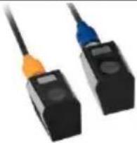
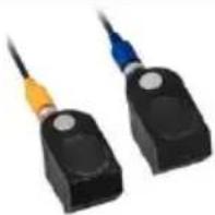
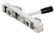
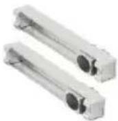
| Sensor type / order code | PCE-TDS 200 S sensor | PCE-TDS 200 M sensor | PCE-TDS 200 SR sensor | PCE-TDS 200 MR sensor |
 |  |  |  | |
| Sensor cable length | 5 m approx. 197 in | 5 m approx. 197 in | 5 m approx. 197 in | 5 m approx. 197 in |
| Nominal diameter | DN 15 ... 10020 ... 108 mmapprox. 3/4 ... 4 in | DN 50 ... 70057 ... 720 mmapprox. 2 ... 28 in | DN 15 ... 10020 ... 108 mmapprox. 3/4 ... 4 in | DN 50 ... 70057 ... 720 mmapprox. 2 ... 28 in |
| Liquid temperature | -30 ... 160 °C-22 ... 320 °F | -30 ... 160 °C-22 ... 320 °F | -30 ... 160 °C-22 ... 320 °F | -30 ... 160 °C-22 ... 320 °F |
| Dimensions | 45 x 30 x 30 mm1.7 x 1.1 x 1.1 in | 70 x 40 x 40 mm2.8 x 1.6 x 1.6 in | 200 x 25 x 25 mm7.9 x 1.0 x 1.0 in | 280 x 40 x 40 mm11.0 x 1.6 x 1.6 in |
| Weight | 75 g / 0.16 lb | 260 g / 0.57 lb | 250 g / 0.55 lb | 1080 g / 2.38 lb |
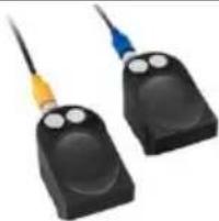
| Sensor type / order code | PCE-TDS 200 L sensor |
 | |
| Sensor cable length | 5 m |
| Nominal diameter | DN 300 ... 6000300 ... 6000 mm |
| Liquid temperature | -30 ... 160 °C |
| Dimensions | 91 x 52 x 44 mm |
| Weight | 530 g |
3.2 Delivery contents
• 1 x ultrasonic flow meter PCE-TDS 200
- 2 x flow sensor (depending on the model)
• 2 x temperature sensor TF-RA330 (PCE-TDS 200+ models only)
- 2 x 5 m connection cable
- 2 x Velcro cable tie
- 1 x mains adaptor
- 1 x USB-C cable
• 1 x ultrasonic coupling gel
- 1 x PCE tape measure
- 1 x plastic carrying case
- 1 x user manual
3.3 Models of the series
The delivery and functional scope of the PCE-TDS 200 series depends on the model. A basic distinction is made between the PCE-TDS 200 and PCE-TDS 200+ product series. The devices of the PCE-TDS 200 product series are mere flow meters. In addition to measuring flow, the devices of the PCE-TDS 200+ series also measure the heat output and heat quantity. Therefore, two TF-RA330 temperature sensors are always included with these devices. The models with their included sensors are listed below. Each model is also available as a PCE-TDS 200+ version.
| Product code | Sensors included |
| PCE-TDS 200 S | 2x PCE-TDS 200 S sensor |
| PCE-TDS 200 M | 2x PCE-TDS 200 M sensor |
| PCE-TDS 200 L | 2 x PCE-TDS 200 L sensor |
| PCE-TDS 200 SM | 2 x PCE-TDS 200 S sensor2 x PCE-TDS 200 M sensor |
| PCE-TDS 200 SL | 2 x PCE-TDS 200 S sensor2 x PCE-TDS 200 L sensor |
| PCE-TDS 200 ML | 2 x PCE-TDS 200 M sensor2 x PCE-TDS 200 L sensor |
| PCE-TDS 200 SR | 1x PCE-TDS 200 SR sensor |
| PCE-TDS 200 MR | 1x PCE-TDS 200 MR sensor |
3.4 Optional accessories
| Product code | Description |
| PCE-TDS 200 S Sensor | Flow sensors for pipes DN 15 ... 100 (without rail) |
| PCE-TDS 200 M Sensor | Flow sensors for pipes DN 50 ... 700 (without rail) |
| PCE-TDS 200 L Sensor | Flow sensors for pipes DN 300 ... 6000 (without rail) |
| PCE-TDS 200 SR Sensor | Flow sensors for pipes DN 300 ... 6000 (on rail) |
| PCE-TDS 200 MR Sensor | Flow sensors for pipes DN 300 ... 6000 (on rail) |
| TT-GEL | Ultrasonic coupling gel for temperatures-10 ... 80 °C / +14 ... +176 °F (100 ml) |
| K-GEL | Ultrasonic coupling gel for temperatures up to 350 °C / +662 °F (100 ml) |
| PCE-TDS 200-SC05 | 2 x 5 m sensor cable for PCE-TDS 200 Series |
| Temperature sensor TF-RA330 | Pipe contact sensor (PCE-TDS 200+ only) |
| PCE-TDS 200 SW | Software for flow meter |
4 System description
4.1 Device
Front side
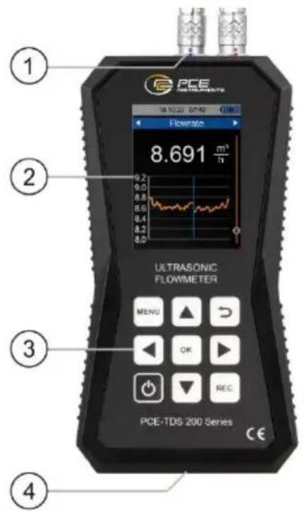
Top side
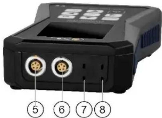
-
Sensor sockets
-
Display
- Keys
- USB port
- Flow sensor connection (front sensor)
- Flow sensor connection (back sensor)
- Temperature sensor connection (channel 2)
- Temperature sensor connection (channel 1)
4.2 Function keys
| Key | Description | Function |
 | ON/OFF | Turn meter on/off |
 | MENU | Open main menu |
 | BACK | Cancel, return, reset maximum value |
 | OK | Confirm |
 | REC | Open data logger dialogue |
 | UP | Navigate up |
 | DOWN | Navigate down |
 | RIGHT | Navigate right |
 | LEFT | Navigate left |
5 Getting started
5.1 Power supply
The meter is powered by an internal rechargeable LiPo battery. With a fully charged battery, an operating time of approx. 8 ... 10 hours is possible, depending on the brightness of the display. The battery is charged via the USB socket at the bottom of the meter, using a suitable USB charger. The charging process can be shortened by switching off the device during the charging process.
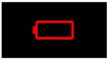
The current charge level of the battery is displayed in the status bar at the top right. As soon as the charge level of the battery is no longer sufficient for proper operation of the instrument, it switches off automatically and the screen shown below is displayed.
natural_image
Simple red battery icon on black background (no text or symbols)Fig. 1 Automatic power off
5.2 Preparation
The meter is switched on by pressing the ON/OFF key. When the device is switched on, the start screen appears for approx. 1 second and then the device enters the measurement screen. To switch off the meter, keep the ON/OFF key pressed. A dialogue with a countdown now appears on the display to announce that the instrument is about to power off.
The flow sensors are connected by simply plugging them into the sockets provided at the top of the device. They are disconnected by pulling the plugs, touching the ribbed surface to unlock the plug connection. Screw the plugs into the sensors using the knurled nut.
The thermocouples are also connected by plugging them into the sockets provided. The plugs have a wide and a narrow contact. These determine the orientation of the plug when it is plugged in.
6 Menu
The main menu can be opened at any time by pressing the MENU key. The arrow keys are used to navigate between the menu items which can be activated with the OK key. Submenus can be left with the BACK key. The main menu of the PCE-TDS 200 series consists of the submenus Measurement, Data logger, Settings, Calibration, Manual and Info. The submenus are explained in more detail in the following chapters.
6.1 Measurement
In the submenu Measurement, the options relevant for the measurement can be set: Pipe, medium, sensors, measurement method, temperature, units, alarm, overview display, damping, absolute values and lower threshold.
6.1.1 Pipe
In the Pipe menu, all parameters of the pipe are set. The following parameters are to be set:
| Parameter | Description |
| S | Material of the pipeSelection of standard materials or custom entry of the transversal sound velocityCustomSee 6.1.1.1MetalsCopper CUSteel FESTainless steel VAAluminium ALBrass MECast iron CIIron FENickel NITitanium TIZinc ZIPlasticsAcrylic ACPolyethylene PEPolypropylene PPPolyvinylchloride PVCNylon NYStainless steelsV2AV4A1.43011.43051.43071.43101.44011.44041.45411.4550 |
| • AISI 302• AISI 303• AISI 304• AISI 304L• AISI 316• AISI 316Ti• AISI 321• AISI 347The abbreviations for the standard materials are shown in the Pipe menu in the Pipe material menu item. | |
| Pipe wall thickness | Wall thickness of the pipe |
| Inner diameter | Inner diameter of the pipe |
| Outer diameter | Outer diameter of the pipe |
| Liner material | Material of the pipe linerSelection of standard materials or custom entry of the longitudinal sound velocity• No liner• Custom• Epoxy resin• Rubber• Mortar• Polystyrol PS• Polyethylene PE• Polytetrafluorethylene PTFE• Polyurethane PU• Polypropylene PP |
| Wall thickness of liner | Wall thickness of the der pipe liner |
The material selection is made via selection menus. The numerical parameters are edited via an input dialogue. Each decimal place can be selected with the RIGHT/LEFT arrow keys and edited with the UP/DOWN arrow keys.
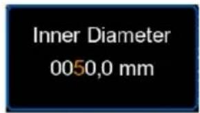
Fig. 2 Input dialogue
To completely set the pipe parameters, first set the pipe material via the selection menu. Then enter the wall thickness of the pipe via an input dialogue. In the next step, you can enter either the inner or the outer diameter; the other variable is calculated automatically on the basis of the parameters. The last settings to be entered are the liner material and the wall thickness of the lining.
The pipe parameters that have now been completely set can be saved as a preset to avoid having to enter all the parameters again. To save the parameters, select the menu item Save as preset. Successful storage is confirmed by a dialogue.
The saved presets are now listed in the Presets menu. The name of the presets is composed of the material abbreviation, the outer diameter, the inner diameter and the pipe wall thickness. By selecting a preset, all pipe parameters are adopted.
6.1.1.1 Custom pipe materials
In this menu, it is possible to create up to 100 user-defined pipe materials. To create a new pipe material, select the menu item Add material and enter the desired name using the keyboard and confirm with the Enter symbol at the bottom right of the keyboard.
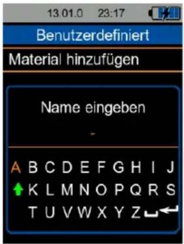
After confirming, a dialog for entering the transverse sound velocity of the material opens.
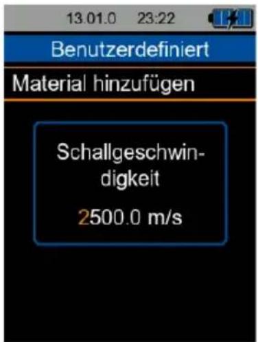
After confirming with the OK button, the material is saved and executed in the list. Selecting the material opens a dialog that displays the properties of the material and contains the options Select, Edit and Delete.
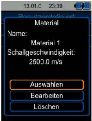
Fig. 5 Dialog for selecting, editing and deleting a pipe material
6.1.2 Medium
The Medium menu allows you to select one of the standard media or to enter the sound velocity and kinematic viscosity of a user-defined medium. The following standard media are available:
- Water
- Sea water
• Oil - Crude oil
- Methanol
- Ethanol
- Diesel
- Gasoline
- Petroleum
A user-defined medium is selected by entering the sound velocity and the kinematic viscosity of the medium. To do this, select the menu item Custom. A dialogue for entering the sound velocity opens. Here, each decimal place can be selected with the RIGHT/LEFT arrow keys and edited with the UP/DOWN arrow keys.
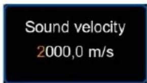
Fig. 6 Input dialogue sound velocity
Then confirm with the OK key. The dialogue changes so that you can enter the kinematic viscosity. Enter the kinematic viscosity of your medium and confirm again with the OK key. The dialogue is closed and the parameters are adopted.
Note: The kinematic viscosity can be calculated from the dynamic viscosity and the density of the medium using the following formula.
$$ \text { Kinematic viscosity } [ m m ^ {2} / s ] = \frac {\text { dynamic viscosity } [ m P a \cdot s ]}{1 0 0 0 \cdot \text { density } [ \frac {k g}{m ^ {3}} ]} $$
6.1.3 Sensors
The flow sensors used are selected in the Sensors menu. The following sensors are available for selection.
| Sensor description | Possible measuring methods | Pipe diameter |
| TDS-S | Z, V, N, W | 20 ... 108 mm / 0.79 ... 4.25 in |
| TDS-M | Z, V, N, W | 57 ... 720 mm / 2.24 ... 28.35 in |
| TDS-L | Z, V, N, W | 315 ... 6000 mm / 12.40 ... 236.22 in |
| TDS-SR | V, W | 20 ... 108 mm / 0.79 ... 4.25 in |
| TDS-MR | Z, V, N, W | 57 ... 720 mm / 2.24 ... 28.35 in |
6.1.4 Measurement method
In the Measurement method menu, the method for mounting the sensors is selected. The Z, V, N and W methods are available for selection. A more detailed explanation of the measurement methods can be found in chapter 7.1.
6.1.5 Temperature
The Temperature menu is used to enter the manual compensation temperature. This is used for compensation of the sound velocity and the kinematic viscosity for the medium water (all other media are not temperature compensated).
In addition, the thermocouple types and any offsets required for the two temperature measurement channels are set in this menu (PCE-TDS 200+ only).
To set a thermocouple type, select the Type menu item for the desired channel with the OK key. The thermocouple type displayed in the menu item on the right now appears in orange. With the arrow keys UP/DOWN, you can now select between the different types (B,E,J,K,N,R,S,T). The setting is adopted by confirming with the OK key again.
To enter an offset, select the corresponding menu item by pressing the OK key. A dialogue for entering the offset opens.
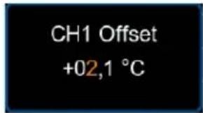
Fig. 7 Input dialogue offset channel 1
Here, each decimal place can be selected with the RIGHT/LEFT arrow keys and edited with the UP/DOWN arrow keys.
6.1.6 Units
This menu allows you to set the units of all measured parameters. The following chart shows the available units.
| Parameter | Unit | Abbreviation |
| Dimensions | Millimetres | [mm] |
| Inches | [in] | |
| Flow velocity | Metres per second | [m/s] |
| Feet per second | [ft/s] | |
| Volume flow | Cubic metres | [m3] |
| Litres | [l] | |
| USA gallons | [gal] | |
| Imperial gallons | [igl] | |
| Million USA gallons | [mgl] | |
| Cubic feet | [cf] | |
| USA barrels | [bal] | |
| Imperial barrels | [ib] | |
| Oil barrels | [ob] | |
| The time can be specified per day, per hour, per minute and per second. | ||
| Volume | Cubic metres | [m3] |
| Litres | [l] | |
| USA gallons | [gal] | |
| Imperial gallons | [igl] | |
| Million USA gallons | [mgl] | |
| Cubic feet | [cf] | |
| USA barrels | [bal] | |
| Imperial barrels | [ib] | |
| Oil barrels | [ob] | |
| Temperature | Celsius | [°C] |
| Fahrenheit | [°F] | |
| PCE-TDS 200+ | ||
| Heat quantity | Joules | [J] |
| Kilojoules | [kJ] | |
| Megajoules | [MJ] | |
| Watt hours | [Wh] | |
| Kilowatt hours | [kWh] | |
| Megawatt hours | [MWh] | |
| British thermal units | [Btu] | |
| Kilo British thermal units | [kBtu] | |
| Mega British thermal units | [MBtu] | |
| Heat output | Watts | [W] |
| Kilowatts | [kW] | |
| Megawatts | [MW] | |
| Joules per hour | [J/h] | |
| Kilojoules per hour | [kJ/h] | |
| Megajoules per hour | [MJ/h] | |
| British thermal units per hour | [Btu/h] | |
| Kilo British thermal units per hour | [kBtu/h] | |
| Mega British thermal units per hour | [MBtu/h] | |
| Cost | Euros | € |
| Pounds | £ | |
| Dollars | $ | |
| Turkish lira | TL | |
| Złoty | Zt | |
| Yuans | ¥ | |
| The costs per unit of heat quantity (for example costs per kWh) can be entered via a dialogue by selecting the menu item Costs per unit. | ||
6.1.7 Alert
The configuration for the visual and audible alarm of the meter is carried out in the Alert menu. Five modes are available for monitoring.
| Mode | Description |
| Off | The alarm is deactivated. |
| Above | The alarm is triggered when the measured parameter exceeds the upper limit value. |
| Below | The alarm is triggered when the measured parameter falls below the lower limit value. |
| Window mode | The alarm is triggered when the measured parameter lies between the upper and the lower limit value. |
| Inverse window mode | The alarm is triggered when the measured parameter lies outside the range between the upper and the lower limit value. |
In addition to selecting the alert mode, the measured parameter to be monitored can be selected under the menu item Measured parameter.
The limit values can be set under the menu item Limits by selecting the respective menu item with the help of an input dialogue.
6.1.8 Overview screen
The meter enables the numerical and graphical display of several measured parameters in the measurement display, the Overview screen. It is possible to display up to four individually selectable measured parameters numerically and up to two individually selectable measured parameters graphically. The selection of the measured parameters to be displayed is made under the menu items Graphical view and Numerical view by placing check marks.
6.1.9 Damping
The damping influences the measured parameters flow velocity and volume flow. It can be set to a value within the range of 0 ... 60 s. The setting 0 s deactivates the damping of the measurement.
6.1.10 Absolute values
The Absolute values menu item makes it possible to prevent negative values from being displayed for the parameters flow velocity and volume flow. With the setting ON, in case of a negative volume flow, the measured value is displayed with a positive sign. The arrangement of the upstream and downstream sensor thus has no influence on the sign in front of the measured values in terms of the flow direction.
6.1.11 Lower cutoff
The Lower cutoff represents the flow velocity above which the meter displays a flow velocity of 0 m/s. In the event that the zero point fluctuates despite a set zero point, this value can be increased.
6.1.12 Distance indication
This option can be used to show or hide the distance display in the installation view. The distance display is hidden by default.
6.1.13 Reset settings
This menu item can be used to reset the settings from the Measurement menu to the following default values. The reset must also be confirmed in a dialog.
| Parameter | Default value |
| Pipe material | Copper |
| Inner diameter | 50 |
| Pipe wall thickness | 1 |
| Liner material | No liner |
| Wall thickness of liner | 0 |
| Medium | Water |
| Sensors | TDS-M |
| Measurement method | V-Method |
| Damping | 10 s |
| Lower cutoff | 0,05 m/s |
6.2 Settings overview
The settings overview shows all parameters relevant for the measurement as well as the signal quality.
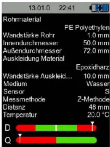
Fig. 8 Overview of all measurement settings
The overview is particularly useful for support requests in order to provide our support staff with all relevant information. In this case, a photo of the sensors on the pipe is also helpful to identify and resolve potential faults.
6.3 Data logger
The Data logger of the instrument allows to record all measured parameters. The time period as well as the memory interval can be freely configured with the help of this menu.
Note: To prevent the meter from accidentally switching off during recording, manual switch-off is not possible and automatic power off is deactivated.
6.3.1 Start condition
The data logger can be started either manually by pressing a key while you are in the data logger dialogue or automatically from a date that is set in this menu.
6.3.2 Stop condition
Three different options are available for stopping the data logger. It can be stopped manually by pressing a key when you are in the data logger dialogue, on a certain date or after an adjustable time interval.
6.3.3 Interval
The time interval for saving the measured values can be set to a value between 1 s and 12 h via an input dialogue.
6.3.4 Records
In this menu, all saved records are displayed and by selecting a record, information on the start and stop time as well as the number of saved data points are displayed. One data point reflects the one-time storage of all measured parameters listed hereinafter for the models PCE-TDS 200 and PCE-TDS 200+.
| Model | Saved measured parameter per data point |
| PCE-TDS 200 | Flow velocity, volume flow, volume |
| PCE-TDS 200+ | Flow velocity, volume flow, volume, temperature channel 1, temperature channel 2, temperature difference, heat output, heat quantity, cost |
Note: If the maximum number of 100,000 data points for the current recording is reached, the device automatically starts another new recording.
6.3.5 Delete all
By selecting this menu item and confirming via the dialogue, all saved data records are deleted.
6.3.6 Data logger dialogue
The data logger dialogue can be opened in any screen via the REC key and shows the current settings as well as the status of the data logger. When the dialogue is open, a recording can be started or stopped at any time by pressing and holding OK. In addition, the data logger menu opens when the dialogue is open and the MENU key is pressed.
Note: If the maximum number of records (a maximum of 100 records is possible) is reached, the error message SD card error is displayed in the dialogue. In this case, it is necessary to delete one or more records to be able to add more records.
6.4 User menu
With the PCE-TDS 200, up to 10 different users can be stored in the menu, whereby the measuring device can be protected with a 4-digit password. When a data recording is carried out, it is noted in the log which user carried out the measurement and which user calibrated the measuring device.
6.4.1 Creating users
You can create a maximum of 10 users in the user menu. A maximum of 25 characters are available for the name and 4 numbers for the password.
6.4.2 Delete user
Users can be deleted in this menu. You need the respective password to delete a user.
6.4.3 Change password
The password entered can be changed here.
If you have forgotten the password, press the UP/DOWN arrow buttons simultaneously for 5 seconds; the password is then reset and a new password must be assigned.
6.4.4 User login
Here you can set whether the meter uses the user login when it is switched on. This setting then applies to all created users. You can activate the user login, in which case each user must log in with the stored password, or you can deactivate the user login, in which case the device starts without a login.
6.5 Setting
6.5.1 Decimal separator
Either a dot or a comma can be selected as the decimal separator for measured values.
6.5.2 Date & time
The date and time can be set in this menu. In addition, the date and time format can be selected.
6.5.3 Display
In this tab, the screen brightness can be adjusted between 50 and 100 %. Automatic dimming can also be set. After the set time, the display is dimmed to a lower brightness to save power or switched off completely. Pressing any button returns the brightness to the original setting.
6.5.4 Language
The following menu languages are available: English, German, French, Spanish, Italian, Dutch, Portuguese, Turkish, Polish, Russian and Chinese.
Note: To reset an incorrectly set language, switch off the meter using the ON/OFF key. Then switch on the meter while pressing and holding the BACK key. You will automatically be taken to the language settings. The default setting of the meter is English.
6.5.5 Auto power off
This option can be used to activate an automatic power-off function for the device. The instrument switches off when the auto power off mode is activated if no key has been pressed for a certain period of time. You can select 1 minute, 5 minutes or 15 minutes. In addition, automatic power-off can be completely deactivated.
6.5.6 Factory settings
With the help of this option, the device can be reset to the factory settings. A distinction is made between the device settings and the pipe presets. These can be reset separately.
When resetting the device settings, the default values for the measurement parameters and the remaining menu options are restored.
When resetting the pipe presets, all presets saved on the meter will be deleted.
6.6 Calibration
The Calibration menu allows you to set a scaling factor that can be determined by calibration. Since a special measurement setup is required for calibration, this menu is protected by a code.
Please send the device to PCE Instruments for calibration. You will find our contact details at the end of the manual.

PCE
INSTRUMENTS
6.7 Manual
A QR code is displayed in this menu. The QR code can be scanned with an appropriate reader such as a mobile phone and leads directly to this user manual.
6.8 Info
The Info menu displays the model name, serial number and firmware version.
7 Measurement
7.1 Measuring principle and measuring methods
The flow meter enables the flow velocity of liquids in pipes to be measured without interfering with the pipe and without affecting the flow in the pipe. However, it does not matter whether the piping is unpainted or painted.
To enable non-invasive measurement, the PCE-TDS 200 uses two sensors that work as both ultrasonic transmitters and receivers. The sensors are attached to the outside of the pipe wall at a defined distance. To enable the transmission of the ultrasound, a coupling gel must be applied to the sensors in this case. When ultrasonic signals are transmitted with and against the flow direction of the liquid, differences in transit time occur which can be converted into the flow velocity.
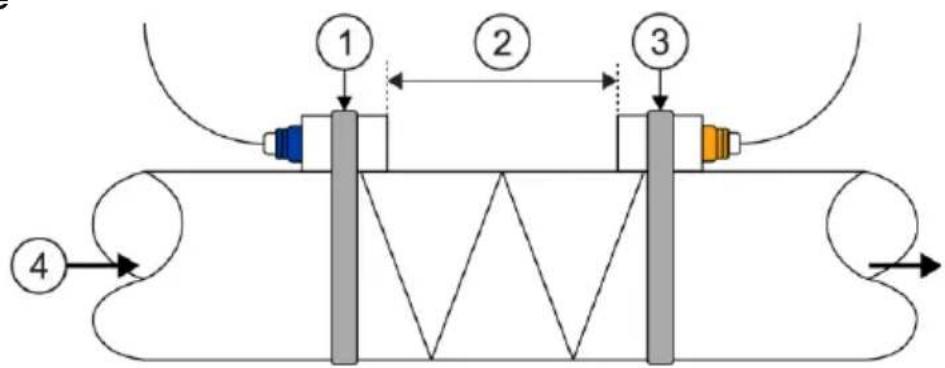
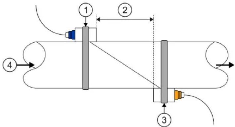
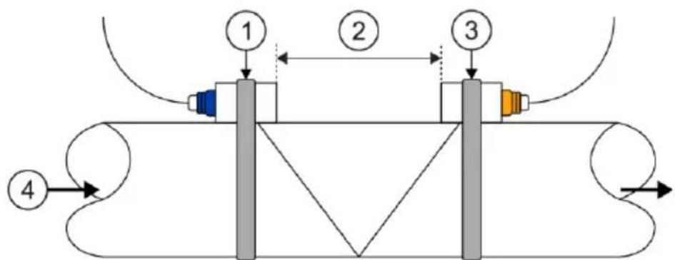
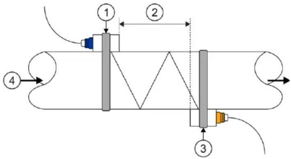
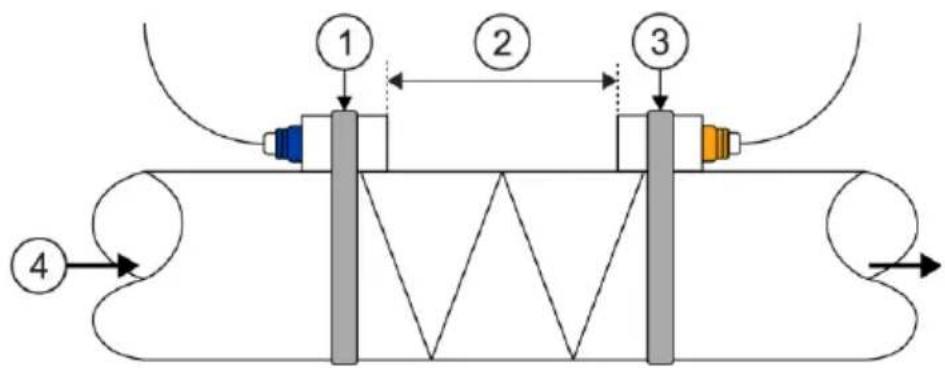
The sensors can be mounted according to four different measurement methods which are shown below.
Z method
V method
flowchart
graph TD
    A["①"] --> B["②"]
    B --> C["③"]
    D["④"] --> E["④"]
    style A fill:#f9f,stroke:#333
    style B fill:#bbf,stroke:#333
    style C fill:#bfb,stroke:#333
    style D fill:#fff,stroke:#333
    style E fill:#fff,stroke:#333
flowchart
graph TD
    A["①"] --> B["②"]
    B --> C["③"]
    C --> D["④"]
    style A fill:#f9f,stroke:#333
    style B fill:#ccf,stroke:#333
    style C fill:#cfc,stroke:#333
    style D fill:#fcc,stroke:#333
W method
flowchart
graph TD
    A["①"] --> B["②"]
    B --> C["③"]
    C --> D["④"]
    style A fill:#f9f,stroke:#333
    style B fill:#ccf,stroke:#333
    style C fill:#cfc,stroke:#333
    style D fill:#fcc,stroke:#333
1 Upstream sensor, 2 Sensor distance, 3 Downstream sensor, 4 Flow direction
The more frequently the sound crosses the liquid, the more accurately even very small flow velocities can be measured. However, the signal strength decreases with each crossing, which is why the W and N method cannot be used for every pipe, for example.
It is recommended to use the V method if the pipe parameters allow it as this produces the best results in terms of signal quality and zero point stability. However, if the signal quality is too low, the Z method can be used.
7.2 Getting started
7.2.1 Measuring location
The first step of the installation should be to find a suitable place to mount the sensors. This is a prerequisite for obtaining accurate measurement results. For this, a basic knowledge of the pipelines / the piping system is necessary.
Therefore, an infinitely long, straight pipe would be the ideal position. The liquid should not have any air pockets or impurities. The piping can be vertical or horizontal. To avoid inaccuracies due to turbulence in the liquid, a straight flow-calming section should be considered upstream and downstream of the measuring location. Generally speaking, the length upstream of the measuring location should be at least 10 x the pipe diameter and downstream of the measuring location 5 x the pipe diameter.
The following chart shows some examples of good positions:
| Pipe routings and sensor position | Upstream | Downstream | |
| L_up × | L_dn × | ||
 | 10D | 5D | |
 | 10D | 5D | |
 | 10D | 5D | |
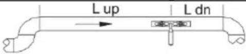 | 12D | 5D | |
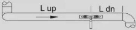 | 20D | 5D | |
 | 20D | 5D | |
 | 30D | 5D | |
7.2.2 Sensor installation
The PCE-TDS 200 has piezoelectric sensors which can transmit and also receive ultrasonic waves. The time the ultrasonic waves take to pass through the pipe walls and the liquid allows conclusions about the flow velocity. Since the transit time of the ultrasonic pulses is very short, the sensors should be installed as precisely as possible to ensure highest system accuracy.
Take the following steps to install the sensors:
(1) Some pipes have a liner. There can be a boundary layer between the outer diameter of the pipe and the inner liner. This boundary layer can divert or weaken the ultrasonic waves. In this case, a measurement will be very difficult. The same applies to external coatings on the pipe, such as paint. This must be removed before the measurement so that you can measure.

PCE INSTRUMENTS
(2) Find an ideal position in the piping system, i. e. a straight section with new and clean pipes with even surfaces.
(3) It is very important that the pipes are clean. Grind or polish the locations where you would like to place the sensors so that the contact surface is even.
(4) There must not be an air gap between the sensors and the surface of the pipe. Attach the sensors using sufficient contact gel. Also, tighten the fastening straps firmly enough so that the position of the sensors cannot change during the measurement.
(5) To avoid air bubbles from causing measurement errors, place the sensors on the pipe laterally. Note that in this case, the flow could not be calculated correctly by the device due to the pipe not being completely filled.
7.2.3 Spacing between the sensors
The distance between the upstream and the downstream sensor can be seen in the installation view of the measurement screen (see 7.4). The window specifies the inner distance between the two sensors which can be used as an indication for the sensor installation. The fine adjustment is carried out by arranging the spacing in a way that the distance indicator is as central as possible within the graph (see 7.3).
In order for the PCE-TDS 200 to calculate the correct distance, the following parameters must be entered beforehand:
(1) Outer diameter of the pipe
(2) Material thickness of the pipe
(3) Material of the pipe
(4) Material thickness of the pipe liner
(5) Material of the pipe liner
(6) Type of liquid
(7) Type of connected sensors
(8) Mounting method of the sensors
(9) Temperature of the medium
7.3 Procedure
Before making the measurement, also read the previous chapters 7.1 and 7.2 to gain an understanding of the measurement principle and its influencing factors.
To carry out a measurement, it is first necessary to set all parameters in the Measurement menu (see 6.1) completely in line with the pipe used, the medium, the sensors, the measurement method and the temperature. After all parameters have been set and checked, go back to the measurement screen and navigate to the installation view. The installation view shows the measurement method, the set sensors and the distance between the sensors.
Note:
Note that in the case of the Z method, the sensors may also overlap.
Mount the sensors according to the described measurement method with the appropriate distance and apply sufficient coupling gel to the sensors. The meter should now be able to receive a signal and display this via the quality indicator. If the quality indicator is within the green range, you can continue with the distance setup. If there is no signal or a poor signal, check the settings again and follow the preparation steps described in chapters 7.1 and 7.2.
Now adjust the distance of the sensors so that the distance indicator is as central as possible within the green area. A good setting is shown below.
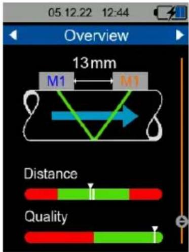
Fig. 9 Installation view with good setting
After setting the distance, the meter is ready for operation and the measurement can be made.
Since the zero point may be shifted depending on the measuring conditions (installation, pipe material, etc.), it is possible to reset the zero point in the installation view. To do this, it is necessary to ensure that the liquid in the pipe does not move!
In the installation view, press and hold the OK key until the confirmation dialogue opens and confirm the setting of the zero point. While the meter is determining the zero point, a waiting dialogue is displayed. After this has closed, the zero point is set.
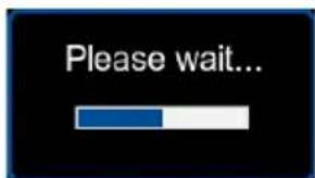
Fig. 10 Waiting dialogue
In order to carry out a heat quantity and heat output measurement, it is also necessary to connect the temperature sensors to the device and attach them to the corresponding measuring locations. Temperature channel 1 must be attached to the warmer measuring location (e.g. the feed line of a heating system) and channel 2 to the colder measuring location (e.g. the return line of a heating system).
7.4 Measurement display
7.4.1 Navigation
To ensure a clear presentation of the measured parameters, the measurement display consists of several views. Each view represents a measured parameter which is displayed in the upper blue area of the view. Switching between the views of the measured parameters is possible with the RIGHT and LEFT arrow keys.
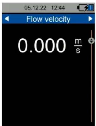
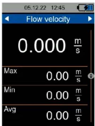
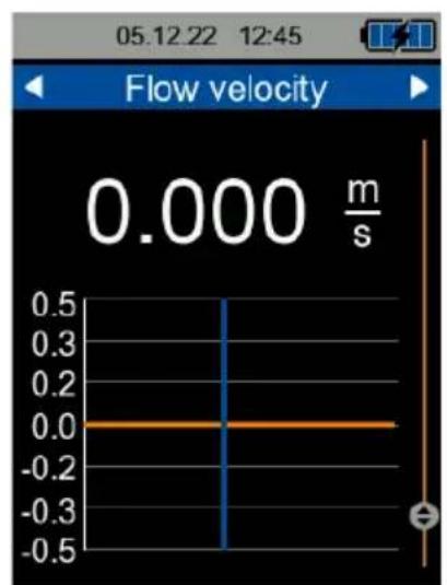
Some parameter views also have several formats for displaying the parameter, such as the simple numerical display, the graphical display or the display of the statistical values (minimum value, maximum value and average). The display format can be changed using the UP and DOWN arrow keys. The following illustrations show the different display formats for viewing the parameter flow velocity.
line
| Time (s) | Flow Velocity (m/s) | | -------- | ------------------- | | 0 | 0.0 | | 1 | 0.0 | | 2 | 0.0 | | 3 | 0.0 | | 4 | 0.0 | | 5 | 0.0 | | 6 | 0.0 | | 7 | 0.0 | | 8 | 0.0 | | 9 | 0.0 | | 10 | 0.0 | | 11 | 0.0 | | 12 | 0.0 | | 13 | 0.0 | | 14 | 0.0 | | 15 | 0.0 | | 16 | 0.0 | | 17 | 0.0 | | 18 | 0.0 | | 19 | 0.0 | | 20 | 0.0 | | 21 | 0.0 | | 22 | 0.0 | | 23 | 0.0 | | 24 | 0.0 | | 25 | 0.0 | | 26 | 0.0 | | 27 | 0.0 | | 28 | 0.0 | | 29 | 0.0 | | 30 | 0.0 | | 31 | 0.0 | | 32 | 0.0 | | 33 | 0.0 | | 34 | 0.0 | | 35 | 0.0 | | 36 | 0.0 | | 37 | 0.0 | | 38 | 0.0 | | 39 | 0.0 | | 40 | 0.0 | | 41 | 0.0 | | 42 | 0.0 | | 43 | 0.0 | | 44 | 0.0 | | 45 | 0.0 | | 46 | 0.0 | | 47 | 0.0 | | 48 | 0.0 | | 49 | 0.0 | | 50 | 0.0 | | 51 | 0.0 | | 52 | 0.0 | | 53 | 0.0 | | 54 | 0.0 | | 55 | 0.0 | | 56 | 0.0 | | 57 | 0.0 | | 58 | 0.0 | | 59 | 0.0 | | 60 | 0.0 | | 61 | 0.0 | | 62 | 0.0 | | 63 | 0.0 | | 64 | 0.0 | | 65 | 0.0 | | 66 | 0.0 | | 67 | 0.0 | | 68 | 0.0 | | 69 | 0.0 | | 70 | 0.0 | | 71 | 0.0 | | 72 | 0.0 | | 73 | 0.0 | | 74 | 0.0 | | 75 | 0.0 | | 76 | 0.0 | | 77 | 0.0 | | 78 | 0.0 | | 79 | 0.0 | | 80 | 0.0 | | 81 | 0.0 | | 82 | 0.0 | | 83 | 0.0 | | 84 | 0.0 | | 85 | 0.0 | | 86 | 0.0 | | 87 | 0.0 | | 88 | 0.0 | | 89 | 0.0 | | 90 | 0.0 | | 91 | 0.0 | | 92 | 0.0 | | 93 | 0.0 | | 94 | 0.0 | | 95 | 0.0 | | 96 | 0.0 | | 97 | 0.0 | | 98 | 0.0 | | 99 | 0.0 | | Note: The data is extracted from the code and presented in CSV format as requested by the code.Fig. 11 Numerical, statistical and graphical representation
The following chart shows the available formats of representation of the measured parameters.
| Flow velocity | Volume flow | Heat output | Heat quantity | Temperature | |
| Numerical | Flow velocity | Volume flow, volume sum, volume positive, volume negative | Heat output | Heat quantity, cost | Temperature channel 1, channel 2 and difference |
| Statistical | Minimum, maximum and average value of the flow velocity | Minimum, maximum and average value of the volume flow | Heat output | - | Minimum, maximum and average value for temperature channel 1, channel 2 and difference |
| Graphical | Flow velocity | Volume flow | Heat output | - | Temperature channel 1, channel 2 |
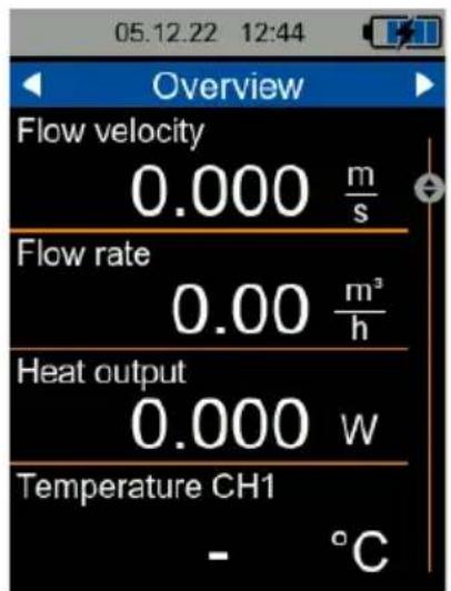
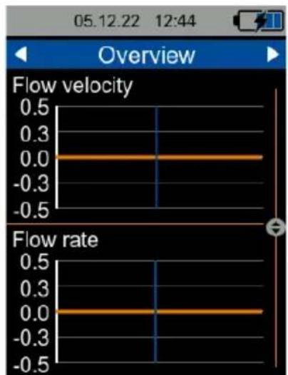
In addition to the parameter views, the measurement display has an overview. The overview shows the numerical and graphical representation as well as the installation view which has already been explained in 7.3.
The numerical display enables the presentation of up to four freely selectable measured parameters. In the graphical display, two measured parameters can be displayed graphically parallel to each other. The selection of the displayed parameters is made via the menu Overview screen described in 6.1.8.
line
| Metric | Value | | -------------- | ----- | | Flow velocity | 0.5 | | Flow rate | 0.5 |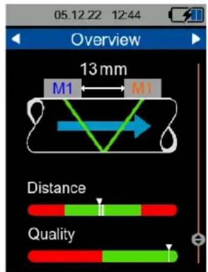
Fig. 12 Formats of representation of the Overview screen
7.4.2 Keyboard shortcuts
To simplify navigation to the overview display, press the BACK key once. Pressing the BACK key again takes you to the installation view.
Resetting the currently displayed statistical values is possible by holding down the OK key. This is possible in the statistical display of the views flow velocity, flow rate, heat output and temperature.
In the numerical displays of the heat quantity and flow rate views, the volume flow counter or the measured heat quantity can be reset to 0 by holding down the OK key.
8 Service
8.1 Measurement
8.1.1 Differences between materials
The reproducibility and measuring accuracy are directly dependent on the input of the pipe and medium parameters. It is therefore important to know the characteristics of the system and to enter them correctly in the settings.
A frequently unknown parameter is the sound velocity of the pipe. If the entered sound velocity does not correspond to the actual sound velocity, the device cannot correctly determine the distance between the sensors, which makes installation more difficult.
The sound velocities stored in the device are average values which may not correspond to the properties of the pipe. Particularly with alloys such as stainless steel, large deviations can occur.
8.1.2 Attaching the sensors
The installation of the sensors is particularly relevant for long-term measurements in order to prevent a change in position. Therefore, make sure that the fastening straps ensure that the sensors are firmly attached. Depending on the application, it may also be helpful to attach the sensor cables to the pipe to prevent the sensors from sagging due to the weight of the sensor cables.
8.1.3 Measurement on small pipes
For pipes with a diameter < 35 mm, installation using the Z method is generally recommended. It is theoretically possible to use the V, N and W methods, but in practice these are more prone to errors during installation, which is why the Z method is recommended in this case.
8.1.4 Function test of the sensors
To test the function of the sensors without the influence of a pipe, proceed as follows.
- set the pipe inside diameter to 20 mm, the pipe wall thickness to 1 mm and select No lining.
- select the Z method.
- navigate to the installation view
- apply some coupling gel to the sensors and hold them in a Z-arrangement on top of each other.
- the quality display should now show a reception quality, provided the sensors are OK.
8.2 Support request
We can best help you with support requests if we have all the necessary information about the measurement application. A summary of the relevant measurement parameters can be found in the device under the settings overview in the Measurement menu (see 5.1.14).
Photos of the sensors on the pipe are also useful for identifying and solving installation problems.
8.3 Firmwareupdate
Download the flash and update software via the following link. https://www.pce-instruments.com/deutsch/software/PCE-TDS-200-plus-flash.zip
- make sure that the measuring device is switched off
- hold the menu button and briefly press the power button after one second.
- then hold the menu button for two more seconds. The screen of the device should now remain black, if the device still starts, the process must be repeated.
- connect the measuring device to the PC via the USB-C cable
- now start the update software. The firmware will now be updated.
- after the update process is complete, the device will start normally.
8.4 Reset language
To reset an incorrectly set language, switch off the meter using the ON/OFF key. Then switch on the meter while pressing and holding the BACK key. You will automatically be taken to the language settings. The default setting of the meter is English.
9 Contact
If you have any questions, suggestions or technical problems, please do not hesitate to contact us. You will find the relevant contact information at the end of this user manual.
10 Disposal
For the disposal of batteries in the EU, the 2006/66/EC directive of the European Parliament applies. Due to the contained pollutants, batteries must not be disposed of as household waste. They must be given to collection points designed for that purpose.
In order to comply with the EU directive 2012/19/EU we take our devices back. We either re-use them or give them to a recycling company which disposes of the devices in line with law.
For countries outside the EU, batteries and devices should be disposed of in accordance with your local waste regulations.
If you have any questions, please contact PCE Instruments.


PCE Instruments contact information
Germany France Spain
PCE Deutschland GmbH PCE Instruments France EURL PCE Ibérica S.L.
Im Langel 26 23, rue de Strasbourg Calle Mayor, 53
D-59872 Meschede 67250 Soultz-Sous-Forets 02500 Tobarra (Albacete)
Unit 11 Southpoint Business Park
Ensign Way, Southampton
Hampshire
United Kingdom, SO31 4RF
Tel: +44 (0) 2380 98703 0
Fax: +44 (0) 2380 98703 9
info@pce-instruments.co.uk
www.pce-instruments.com/english
Italy
PCE Italia s.r.l.
Via Pesciatina 878 / B-Interno 6
55010 Loc. Gragnano Pehlivan Sok. No.6/C
Capannori (Lucca)
Italia
www.pce-instruments.com/turkish
The Netherlands
PCE Brookhuis B.V.
Institutenweg 15
7521 PH Enschede
Nederland
Telefoon: +31 (0)53 737 01 92
info@pcebenelux.nl
www.pce-instruments.com/dutch Fax: +1 (561) 320-9176
info@pce-americas.com
www.pce-instruments.com/us
United States of America
PCE Americas Inc.
1201 Jupiter Park Drive, Suite 8
Jupiter / Palm Beach
33458 FL
USA
Tel: +1 (561) 320-9162
Denmark
PCE Instruments Denmark ApS
Birk Centerpark 40
7400 Herning
Denmark
Specifications are subject to change without notice.


- Introduction
- Specifications
- Technical specifications
- Delivery contents
- Models of the series
- Optional accessories
- System description
- Device
- Front side
- Top side
- Getting started
- Power supply
- Preparation
- Menu
- Measurement
- Pipe
- Custom pipe materials
- Medium
- Sensors
- Measurement method
- Temperature
- Units
- Alert
- Overview screen
- Damping
- Absolute values
- Lower cutoff
- Distance indication
- Reset settings
- Settings overview
- Data logger
- Start condition
- Stop condition
- Interval
- Records
- Delete all
- Data logger dialogue
- User menu
- Creating users
- Delete user
- Change password
- User login
- Setting
- Decimal separator
- Date & time
- Display
- Language
- Auto power off
- Factory settings
- Calibration
- Manual
- Info
- Measurement
- Measuring principle and measuring methods
- Z method
- V method
- Getting started
- Measuring location
- Sensor installation
- PCE INSTRUMENTS
- Spacing between the sensors
- Procedure
- Note:
- Measurement display
- Navigation
- Keyboard shortcuts
- Service
- Measurement
- Differences between materials
- Attaching the sensors
- Measurement on small pipes
- Function test of the sensors
- Support request
- Firmwareupdate
- Reset language
- Contact
- Disposal
- PCE Instruments contact information
- Germany France Spain
- Italy
- The Netherlands
- United States of America
- Denmark
Brand : PCE Instruments
Model : TDS 200 M
Category : Mètre