
EFX 32300 IH - Cooker TEKA - Free user manual and instructions
Find the device manual for free EFX 32300 IH TEKA in PDF.

| Product Type | Gas hob with electric hotplates (Hi-Light) |
| Brand | Teka |
| Model | EFX 32300 IH |
| Number of Gas Burners | 4 (Double crown Wok, Rapid, Semirapid, Auxiliary) |
| Number of Electric Hotplates | 2 (Hi-Light) or more depending on configuration |
| Burner Power Ratings | Wok: 4000 W, Rapid: 3000 W, Semirapid: 1750 W, Auxiliary: 1000 W |
| Electric Hotplate Power | Up to 2400 W (rectangular) or 2100 W (oval) |
| Total Gas Power (Natural) | 7.5 kW (for 4 burners configuration) |
| Total Gas Power (LPG) | 545 g/h (G30) or 536 g/h (G31) |
| Electrical Supply | 220-240 V ~ 50/60 Hz |
| Cut-out Dimensions (W x D) | 553 x 473 mm (for 60 cm models) |
| Gas Connection | 1/2" gas conic male thread; convertible for natural gas or LPG |
| Safety Features | Flame failure device on burners, residual heat indicator on electric plates, child lock (via supervision) |
| Ignition | Automatic electric ignition; manual ignition possible |
| Timer | 60-minute timer for automatic shut-off of heating elements |
| Material | Glass ceramic top (for electric zones), enamelled pan supports and burner caps |
| Cleaning | Wash with lukewarm soapy water; avoid abrasive powders; use silicone conditioner for glass |
| Included Accessories | Pan supports, wok support (for double crown burner), injector kit for gas conversion |
| Installation Requirements | Room volume ≥ 20 m³; ventilation openings ≥ 100 cm²; side walls not higher than hob |
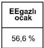
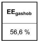
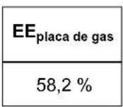
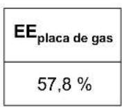
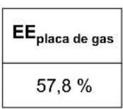
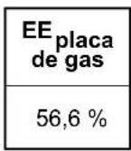
| Energy Efficiency (Gas Burner) | EE gas burner ≥ 56.6% (Wok) to 58.8% (Rapid) per EN 30-2-1 |
Frequently Asked Questions - EFX 32300 IH TEKA
User questions about EFX 32300 IH TEKA
0 question about this device. Answer the ones you know or ask your own.
Ask a new question about this device
Download the instructions for your Cooker in PDF format for free! Find your manual EFX 32300 IH - TEKA and take your electronic device back in hand. On this page are published all the documents necessary for the use of your device. EFX 32300 IH by TEKA.
USER MANUAL EFX 32300 IH TEKA
natural_image
Modern kitchen interior with glossy black cabinets and stainless steel lighting (no visible text or symbols)EFX 70.1 5G AI AL DR CI LEFT
EFX 70.1 5G AI AL DR CI
EFX 60.1 4G AI AL DR CI
EFX 60.1 4G AI AL CI
EFX 60.1 2G 2H AI AL
EFX 90.1 5G AI AL DR CI
EFX 90.1 5G AI AL DR CI LEFT
EFX 90.1 4G 1H AI AL DR
EFX 90.1 4G 2H AI AL
EFX 90.1 6G AI AL DR CI LEFT
EFX 30.1 1G AI AL DR CI
EFX 30.1 2H - EFX 30 2H-T
EFX 30.1 1H - EFX 30 1H-T
EFX 30.1 2G AI AL CI

natural_image
3D rendering of a gas stove with four fans and control knobs (no text or symbols visible)natural_image
3D rendering of a gas stove burner with black and metallic casing (no text or symbols visible)natural_image
Simple line drawing of a pot with liquid and two handles, placed on a surface (no text or symbols)
natural_image
Simple line drawing of a container with liquid and a cross-shaped object above it, no text or symbols present.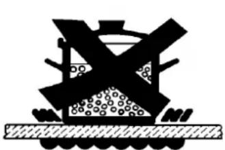
natural_image
Silhouette of a mining machine with a crossed handle and pile of material, no text or symbols present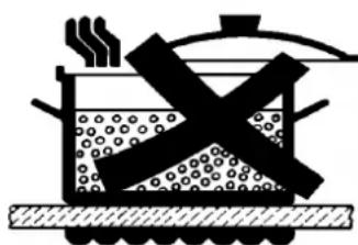
natural_image
Illustration of a cooking pot with steam rising and crossed out by a crossed-out pan (no text or symbols)FIG. 7

TEMİZLEME
ÖNEMLİ:
natural_image
Line drawing of a hand using a tool to clean or inspect a circular component (no text or symbols)ŞEKİL 8
ŞEKİL 8/A
ŞEKİL 8/B
TR
TEMİZLEME
natural_image
Circular petri dish with a dark irregular spot on its surface, no visible text or symbolsFIG. A
For fully electric model
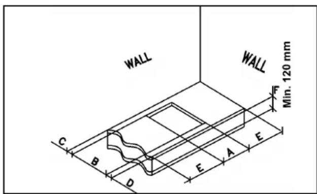
FIG. 9
MONTAJ
natural_image
Simple diagram with four circles and four numbered circles, no text or symbols present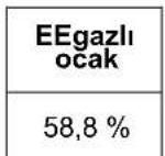
natural_image
Pure diagram of a curved structure with a base and a labeled point B, no text or symbols present.
ŞEKİL 16
$$ G 3 0 - B \ddot {U} T A N = 3 0 m b a r $$
$$ G 3 1 - P R O P A N = 3 0 \mathrm{mbar} $$
$$ G 2 0 - D O G A L G A Z = 2 0 \mathrm{mbar} $$
$$ \text { Tot. Gaz ölçüsü } = 7. 5 \mathrm{kW} $$
$$ \text { Tot. LPG ölcüsü } = 5 4 5 \mathrm{gr/h} $$
$$ \text { Voltaj } = 2 2 0 - 2 4 0 \mathrm{V} \sim $$
$$ \text { Frekans } = 5 0 - 6 0 \mathrm{Hz} $$
4 GAZLI OCAKLAR (60) İKİ TAÇ WOK
$$ \text { KATEGORI } = \mathrm{I} _ {2 \mathrm{H} 3 \mathrm{B} / \mathrm{P}} $$
$$ G 3 0 - B \ddot {U} T A N = 3 0 m b a r $$
$$ G 3 1 - \text { P R O P A N } = 3 0 \mathrm{mbar} $$
$$ G 2 0 - D O G A L G A Z = 2 0 \mathrm{mbar} $$
$$ \text { Tot. Gaz ölçüsü } = 8. 5 0 \mathrm{kW} $$
$$ \text { Tot. LPG ölçüsü } = 6 1 8 \mathrm{gr/h} $$
$$ \text { Voltaj } = 2 2 0 - 2 4 0 \mathrm{V} \sim $$
$$ \text { Frekans } = 5 0 - 6 0 \mathrm{Hz} $$
2 GAZLI + 2 plakalar (60)
$$ \text { KATEGORI } = \mathrm{I} _ {2 \mathrm{H} 3 \mathrm{B} / \mathrm{P}} $$
$$ G 3 0 - B \ddot {U} T A N = 3 0 m b a r $$
$$ G 3 1 - \text { PROPAN } = 3 0 \mathrm{mbar} $$
$$ G 2 0 - D O G A L G A Z = 2 0 \mathrm{mbar} $$
$$ G 3 0 - B \ddot {U} T A N = 3 0 m b a r $$
$$ G 3 1 - P R O P A N = 3 0 \mathrm{mbar} $$
$$ G 2 0 - D O G A L G A Z = 2 0 \text { mbar } $$
$$ \text { Tot. Gaz ölçüsü } = 1 1. 5 \mathrm{kW} $$
$$ \text { Tot. LPG ölçüsü } = 8 3 6 \mathrm{gr/h} $$
$$ \text { Voltaj } = 2 2 0 - 2 4 0 \mathrm{V} \sim $$
$$ \text { Frekans } = 5 0 - 6 0 \mathrm{Hz} $$
5 LÜOCAKLAR (ORTA GÖZÜ WOK) (90)
$$ \text { KATEGORI } = \mathrm{I} _ {2 \mathrm{H} 3 \mathrm{B} / \mathrm{P}} $$
$$ G 3 0 - B \ddot {U} T A N = 3 0 m b a r $$
$$ G 3 1 - \text { P R O P A N } = 3 0 \mathrm{mbar} $$
$$ G 2 0 - D O G A L G A Z = 2 0 \mathrm{mbar} $$
$$ \text { Tot. Gaz ölçüsü } = 1 1. 5 \mathrm{kW} $$
$$ \text { Tot. LPG ölçüsü } = 8 3 6 \mathrm{gr/h} $$
$$ \text { Voltaj } = 2 2 0 - 2 4 0 \mathrm{V} \sim $$
$$ \text { Frekans } = 5 0 - 6 0 \mathrm{Hz} $$
5 LÜOCAKLAR (Çok Hizli ürkek) (75-90)
$$ \text { KATEGORI } = \mathrm{I} _ {2 \mathrm{H} 3 \mathrm{B} / \mathrm{P}} $$
$$ G 3 0 - B \ddot {U} T A N = 3 0 m b a r $$
$$ G 3 1 - \text { P R O P A N } = 3 0 \mathrm{mbar} $$
$$ G 2 0 - D O G A L G A Z = 2 0 \mathrm{mbar} $$
$$ \text { Tot. Gaz ölçüsü } = 1 1. 5 \mathrm{kW} $$
$$ \text { Tot. LPG ölçüsü } = 8 3 6 \mathrm{gr/h} $$
$$ \text { Voltaj } = 2 2 0 - 2 4 0 \mathrm{V} \sim $$
$$ \text { Frekans } = 5 0 - 6 0 \mathrm{Hz} $$
4 LÜOCAKLAR (90) (2 plakalar)
$$ \text { KATEGORI } = \mathrm{II} _ {2 \mathrm{H} 3 \mathrm{B} / \mathrm{P}} $$
$$ G 3 0 - B \ddot {U} T A N = 3 0 m b a r $$
$$ G 3 1 - P R O P A N = 3 0 \mathrm{mbar} $$
$$ G 2 0 - D O G A L G A Z = 2 0 \mathrm{mbar} $$
$$ \text { Tot. Gaz ölçüsü } = 7. 5 \mathrm{kW} $$
$$ \text { Tot. LPG ölcüsü } = 5 4 5 \mathrm{gr/h} $$
$$ \text { Voltaj } = 2 2 0 - 2 4 0 \mathrm{V} \sim $$
$$ \text { Frekans } = 5 0 - 6 0 \mathrm{Hz} $$
$$ \text { Pot. Nom. Elk. Değeri } = 3 0 0 0 \mathrm{W} $$
4 LÜOCAKLAR (90) (1 plakalar oval) ORTA GÖZÜ WOK
$$ \text { KATEGORI } = \mathrm{II} _ {2 \mathrm{H} 3 \mathrm{B} / \mathrm{P}} $$
$$ G 3 0 - B \ddot {U} T A N = 3 0 m b a r $$
$$ G 3 1 - \text { PROPAN } = 3 0 \mathrm{mbar} $$
$$ G 2 0 - D O G A L G A Z = 2 0 m b a $$
6 LÜOCAKLAR (90) ORTA GÖZÜ WOK
$$ \text { KATEGORI } = \mathrm{I} _ {2 \mathrm{H} 3 \mathrm{B} / \mathrm{P}} $$
$$ G 3 0 - B \ddot {U} T A N = 3 0 m b a r $$
$$ G 3 1 - P R O P A N = 3 0 \mathrm{mbar} $$
$$ G 2 0 - D O G A L G A Z = 2 0 \mathrm{mbar} $$
$$ \text { Tot. Gaz ölçüsü } = 1 3. 2 5 \mathrm{kW} $$
$$ \text { Tot. LPG ölcüsü } = 9 6 3 \mathrm{gr/h} $$
$$ \text { Voltaj } = 2 2 0 - 2 4 0 \mathrm{V} \sim $$
$$ \mathrm{Frekans} = 5 0 - 6 0 \mathrm{Hz} $$
Instructions for the installation and advice for the maintenance. Instructions Manual
EFX 70 5G AI AL DR CI LEFT EFX 70 5G AI AL DR CI
EFX 60 4G AI AL DR CI EFX 60 4G AI AL CI
EFX 60 2G 2H AI AL
EFX 90 5G AI AL DR CI EFX 90 5G AI AL DR CI LEFT
EFX 90 4G 1H AI AL DR EFX 90 4G 2H AI AL
EFX 90 6G AI AL DR CI LEFT EFX 30 1G AI AL DR CI
EFX 30 2H - EFX 30 2H-T EFX 30 1H - EFX 30 1H-T
EFX 30 2G AI AL CI
EFX 70.1 5G AI AL DR CI LEFT EFX 70.1 5G AI AL DR CI
EFX 60.1 4G AI AL DR CI EFX 60.1 4G AI AL CI
EFX 60.1 2G 2H AI AL
EFX 90.1 5G AI AL DR CI EFX 90.1 5G AI AL DR CI LEFT
EFX 90.1 4G 1H AI AL DR EFX 90.1 4G 2H AI AL
EFX 90.1 6G AI AL DR CI LEFT EFX 30.1 1G AI AL DR CI
EFX 30.1 2H - EFX 30 2H-T EFX 30.1 1H - EFX 30 1H-T
EFX 30.1 2G AI AL CI

natural_image
3D rendering of a gas stove with four flanges and control knobs (no text or symbols visible)
WARNING: The appliance and its accessible parts become hot during use.
Care should be taken to avoid touching heating elements.
Children less than 8 years of age shall be kept away unless continuously supervised.
This appliance can be used by children aged from 8 years and above and persons with reduced physical, sensory or mental capabilities or lack of experience and knowledge if they have been given supervision or instruction concerning use of the appliance in a safe way and understand the hazards involved.
Children shall not play with the appliance.
Cleaning and user maintenance shall not be made by children without supervision.
WARNING: Unattended cooking on a hob with fat or oil can be dangerous and may result in fire. NEVER try to extinguish a fire with water, but switch off the appliance and then cover flame e.g. with a lid or a fire blanket.
WARNING: Danger of fire: do not store items on the cooking surfaces.
WARNING: If the surface is cracked, switch of the appliance to avoid the possibility of electric shock.
WARNING: do not use a steam cleaning unit of: stoves, hobs and ovens.
WARNING: the hob is not designed to work with an external timer, or with a remote control system.
WARNING: Use only hob guards designed by the manufacturer of the cooking appliance or indicated by the manufacturer of the appliance in the instructions for use as suitable or hob guards incorporated in the appliance. The use of inappropriate guards can cause accidents.
WARNING: The cooking process has to be supervised. A short term cooking process has to be supervised continuously.
DESCRIPTION OF THE HOT PLATES
EFX 60 4G AI AL CIEFX 60.1 4G AI AL CI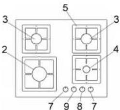 | EFX 30 2G AI AL CIEFX 30.1 2G AI AL CI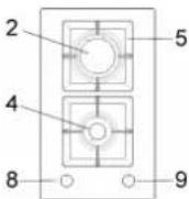 | EFX 70 5G AI AL DR CIEFX 70.1 5G AI AL DR CI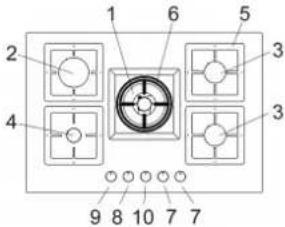 | |
EFX 60 2G 2H AI ALEFX 60.1 2G 2H AI AL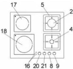 | EFX 30 1G AI AL DR CIEFX 30.1 1G AI AL DR CI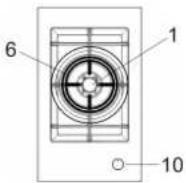 | EFX 60 4G AI AL DR CIEFX 60.1 4G AI AL DR CI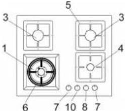 | |
| EFX 90 4G 2H AI ALEFX 90.1 4G 2H AI AL | EFX 30 2HEFX 30.1 2H | EFX 30 2H TEFX 30.1 2H-T | EFX 90 4G 1H AI AL DREFX 90.1 4G 1H AI AL DR |
 |  |  |  |
| EFX 90 5G AI AL DR CIEFX 90.1 5G AI AL DR CI | EFX 30 1H | EFX 30 1H-T | EFX 90 5G AI AL DR CI LEFTEFX 90.1 5G AI AL DR CI LEFT |
 |  |  |  |
| EFX 70 5G AI AL DR CI LEFTEFX 70.1 5G AI AL DR CI LEFT | EFX 90 6G AI AL DR CI LEFTEFX 90.1 6G AI AL DR CI LEFT | ||
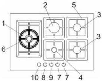 |  |  | 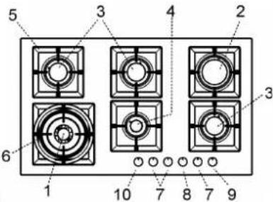 |
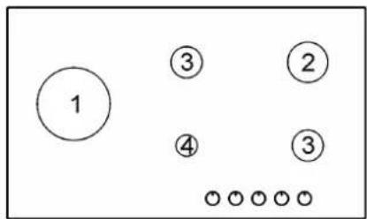
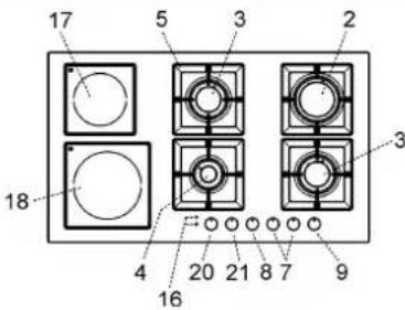
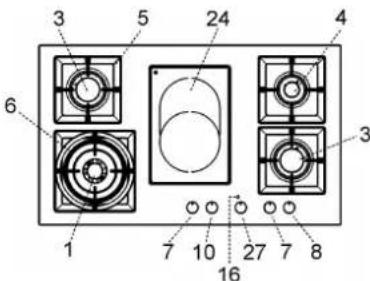
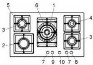
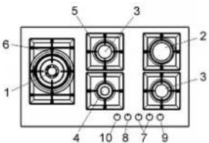
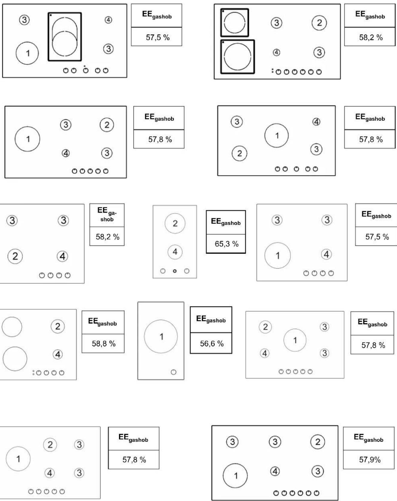
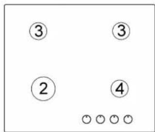
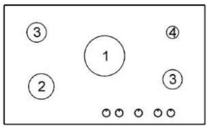
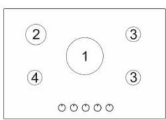
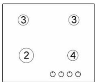
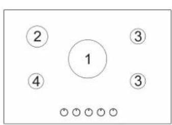
DESCRIPTION OF THE HOT PLATES
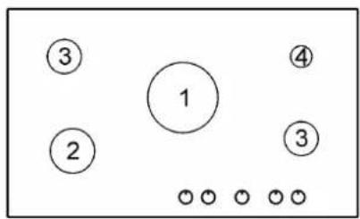
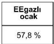
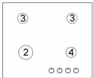
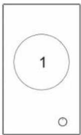
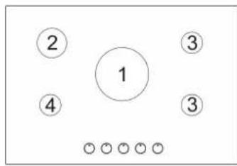
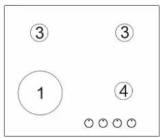
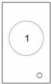
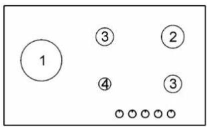
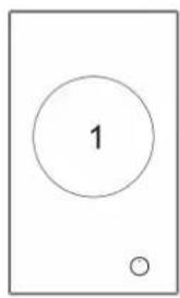
1 Double crown Wok burner of 4000 W
2 Rapid gas burner of 3000 W
3 Semirapid gas burner of 1750 W
4 Auxiliary gas burner of 1000 W
5 Pan support
6 WOK pan support (only on burner double crown)
7 Burner n° 3 control knob
8 Burner n° 4 control knob
9 Burner n° 2 control knob
10 Burner n° 1 control knob
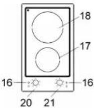
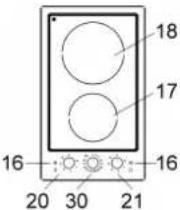
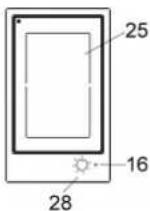
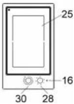
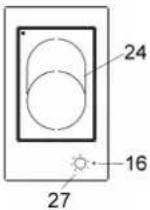
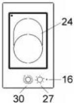
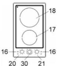
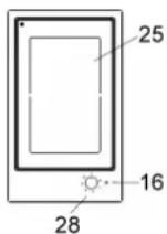
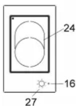
16 Electric ignition button "Hi-light (Residual heat indicator)
17 Electric heating element "Hi-light" ∅ 14,0 de 1200 W
18 Electric heating element "Hi-light" ∅ 18,0 de 1800 W
20 Electric heating element control knob "Hi-light" n° 17
21 Electric heating element control knob "Hi-light n° 18
24 Electrical heating element double oval "Hi-light" ∅ 17,0*26,5 de 1400/2100 W
25 Elemento de calentamiento eléctrico "Hi-light" rectangular 18,5*30,5 cm de 2400 W
27 Electric heating element control knob "Hi-light" n° 24
28 Electric heating element control knob "Hi-light" n° 25
30 Timer control Knob 60'
Attention: this appliance has been manufactured for domestic use only and it employment by private person.
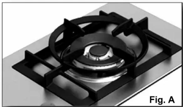
To use the WOK pan support on ultra rapid gas burner only.
Put it on the ultra rapid pan support and make sure of the stability (see fig. A).
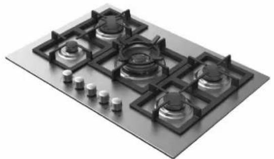
natural_image
3D rendering of a gas stove burner with black and metallic casing (no text or symbols visible)This cook top was designed to be used exclusively as a cooking appliance: any other use (such as heating rooms) is to be considered improper and dangerous.
USE
1) BURNERS
A diagram is screen-printed above each knob on the front panel. This diagram indicates to which burner the knob in question corresponds. After having opened the gas mains or gas bottle tap, light the burners as described below:
- manual ignition
Push and turn the knob corresponding to the required burner in an anticlockwise direction until it reaches the full on position (large flame fig. 1), then place a lighted match near the burner.
- Automatic electrical ignition
Push and turn the knob corresponding to the required burner in an anticlockwise direction until it reaches the full on position (large flame fig. 1), then depress the knob.
- Lighting burners equipped with flame failure device
The knobs of burners equipped with flame failure device must be turned in an anticlockwise direction until they reach the full on position (large flame fig. 1) and come to a stop. Now depress the knob in question and repeat the previously indicated operations.
Keep the knob depressed for about 10 seconds once the burner has ignited.
HOW TO USE THE BURNERS
Bear in mind the following indications in order to achieve maximum efficiency with the least possible gas consumption:
- use adequate pans for each burner (consult the following table and fig. 2).
- When the pan comes to the boil, set the knob to the reduced rate position (small flame fig. 1).
- Always place a lid on the pans.
- Use only pan with a flat bottom.
Burners
Power ratings (kW)
∅ Pan (cm)
Double ring 4000 24 ÷ 26
Rapid 3000 20 ÷ 22
Semirapid 1750 16 ÷ 18
Auxiliary 1000 10 ÷ 14
WARNINGS:
- burners with flame failure device may only be ignited when the relative knob has been set to the Full on position (large flame fig. 1).
- Matches can be used to ignite the burners in a blackout.
- Never leave the appliance unattended when the burners are being used. Make sure there are no children in the near vicinity. Particularly make sure that the pan handles are correctly positioned and keep a chek on foods requiring oil and grease to cook since these products can easily catch fire.
- Never use aerosols near the appliance when it is operating.
- If the built-in hot plate has a lid, any spilt food should be immediately removed from this before it is opened. If the appliance has a glass lid, this could shatter when the hot plate becomes hot. Always switch off all the burners before closing the lid.
- Containers wider than the unit are not recommended.
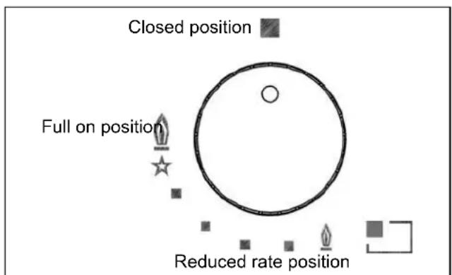
FIG. 1
natural_image
Line drawing of two identical cooking pots with no text or symbolsFIG. 2
USE
WARNINGS AND ADVICE FOR THE USER:
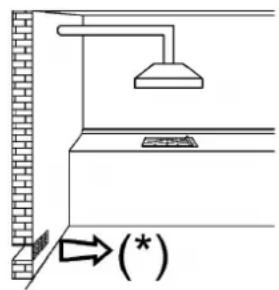
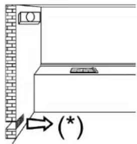
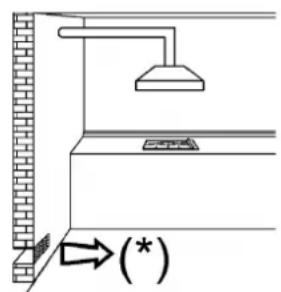
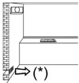
- use of a gas cooking appliance produces heat and moisture in the room in which it is installed. The room must therefore be well ventilated by keeping the natural air vents clear (see fig. 3) and by activating the mechanical aeration device (suction hood or electric fan fig. 4 and fig. 5).
- Intensive and lengthy use of the appliance may require additional ventilation. This can be achieved by opening a window or by increasing the power of the mechanical exhausting system if installed.
- Do not attempt to change the technical characteristics of the product because it can be dangerous.
- If you should not to use this appliance any more (or replace an old model), before disposing of it, make it inoperative in conformity with current law on the protection of health and the prevention of environmental pollution by making its dangerous parts harmless, especially for children who might play on an abandoned appliance.
- Do not touch the appliance with wet or damp hands or feet.
- Do not use the appliance barefoot.
- The manufacturer will not be liable for any damage resulting from improper, incorrect or unreasonable use.
- During, and immediately after operation, some parts of the cook top are very hot: avoid touching them.
- After using the cook top, make sure that the knob is in the closed position and close the main tap of the gas supply or gas cylinder.
- If the gas taps are not operating correctly, call the Service Department.
WARNING: during operation the work surfaces of the cooking area become very hot: keep children away!
Never cook food directly on the electric plates but always in a pot or container.
TIMER
Timer allows to heating elements to turn off automatically by acoustic warning. It can be used also as timer (without turning off) and can be set for a period of max. 60 minutes (see fig. 6).
(*) AIR INLET: SEE INSTALLATION CHAPTER (PARAGRAPHS 6 AND 7)
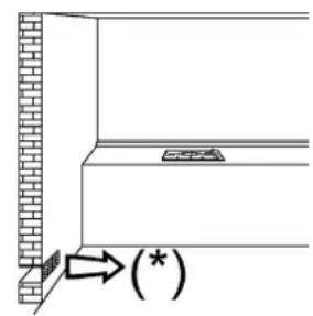
FIG. 3 FIG. 4 FIG. 5
USE
2) SWITCHING ON THE ELECTRIC PLATES "Hi-Ligts"
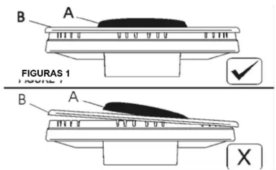
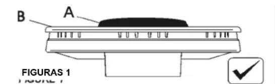
Heating elements are controlled by energy regulators with 12 positions (see fig.A-B) that permit to obtain a big range of different temperatures. In Scheme, by way of information, we give instructions to obtain different cooking levels.
To connect the heating elements is necessary to turn clockwise or anticlockwise the relative knob. Indicator light 16 shows the connection of one or more heating elements.
The indicator will turn off only when the temperature of the cooking zone will be below the value: this is the reason why we call it residual heat indicator.
ACTIVATION OF THE DOUBLE ZONE
To activate the double zone simply rotate the knobs clock wise all the way through to position 0, as shown in fig. no. 6.
In that position it is possible to regulate the temperature, while keeping the Double Zone switched on.
To activate only one single heating element, simply rotate again the knob until position 0 is reached and switch on again, resetting the required heating levels.
How to use the cooking zones
Heating takes place only in the inside part of the circles drawn on the special glass. The circles have to be wholly covered by the pots.
TABLE
Power and size (cm) of the cooking zones
| Zone n° 17 | ∅ 14,0 “Hi-light” | 1200 W | |
| Zone n° 18 | ∅ 18,0 “Hi-light” | 1800 W | |
| Zone n° 24 | ∅ 17,0*26,5 “Hi-light” | 1400/2100 W | |
| Zone n° 25 | ∅ 18,5*30,5 “Hi-light” | 2400 W |
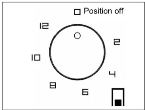
Fig.B
Adjustment positions
knobs control
Possible cooking processes
| 0 - 2 | To dissolve butter, chocolate, etc.. To heat small amounts of liquid. |
| 2 - 4 | To heat larger amounts of liquid.To prepare cremes and suces requiring long slow cooking times. |
| 4 - 6 | To thaw frozen foods and prepare stews, heat to boiling point or simmer. |
| 6 - 8 | To heat foods to boiling point.To brown delicate meats and fish. |
| 8 -10 | For escalopes and steaks. To simmer large amounts of food. |
| 10 - 12 | To bring large amounts of liquid to the boil. For frying. |
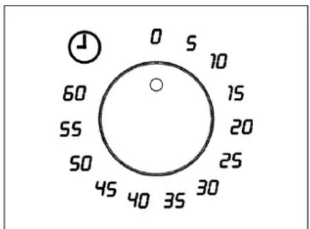
FIG. 6
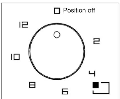
FIG. A
USE
WARNINGS:
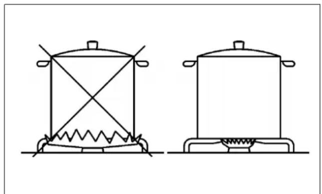
for a correct use, please look at fig. 7 and remind:
- switch on the electricity only after having placed the pot on the cooking zone.
- Use pots and pans with flat solid bottoms.
- Use pots with the same diameter of the cooking zones.
- Dry the bottom of the pot before put in on the cooking zones.
- Do not scrape the pot against the glass so to not damage it.
- During the use of the cooking zones, please, keep the children away from the hot plates. Make sure that the handles of the pots are placed in the right way towards the interior. Be aware that overheated fats and oils may become inflamed.
- Cooking zones after using remain warm; don't leave objects, don't lean your hands so to avoid burns, till the indicator light is off.
- If the glass cracks, please, disconnect the appliance.
- Don't use plastic pots or alluminium sheets.
- Don't use hob as a supplementary surface.
- The appliance must not be operated with an external timer or a separate remote-control system.
- Do not attempt to change the technical characteristics of the product because it can be dangerous.
- If you should not to use this appliance any more (or replace an old model), before disposing of it, make it inoperative in conformity with current law on the protection of health and the prevention of environmental pollution by making its dangerous parts harmless, especially for children who might play on an abandoned appliance.
WARNINGS AND ADVICE FOR THE USER:
- do not touch the appliance with wet or damp hands or feet.
- Do not use the appliance barefoot.
- The manufacturer will not be liable for any damage resulting from improper, incorrect or unreasonable use.
- During, and immediately after operation, some parts of the cook top are very hot: avoid touching them.
- After using the cook top, make sure that the knob is in the closed position.
- cook with a cover whenever possible to save electricity;
- an indicator light near the knob shows when the electric plates are turned on.
CAUTION:
In case of hotplate glass breakage:
- shut immediately off all burners and any electrical heating element and isolate the appliance from the power supply;
- do not touch the appliance surface;
•do not use the appliance.
In order to cook with the heating element efficiently using the least amount of energy, use: thick, flat-bottomed pots of a width suited to that of the heating element (see picture). Cook with the lid on to also save energy. Turn down the heating element when it reaches boiling point.
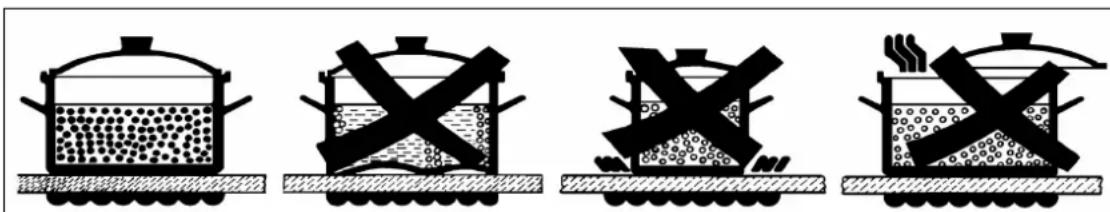
FIG. 7
CLEANING
IMPORTANT:
always disconnect the appliance from the gas and electricity mains before carrying out any cleaning operation.
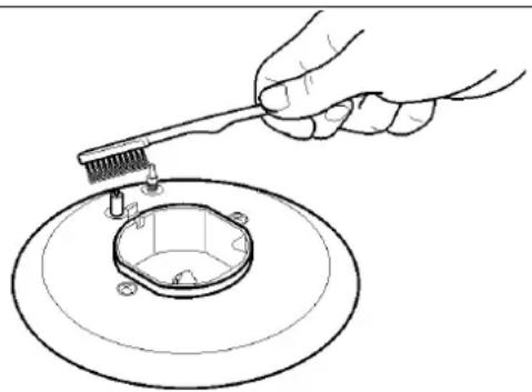
3) HOT PLATE
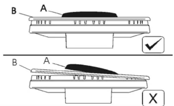
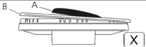
Periodically wash the hot plate, the enamelled stell pan support, the enamelled burner caps "A", "B" and "C" and the burner heads "T" (see fig. 8/A and 8/B) with lukewarm soapy water. They should also be cleaned plugs "AC" and flame detection "TC" (see fig. 8/B). Clean them gently with a small nylon brush as shown (see fig. 8) and allow to dry fully. Do not wash in the dishwasher.
Following this, all parts should be thoroughly rinsed and dried. Never wash them while they are still warm and never use abrasive powders.
Do not allow vinegar, coffee, milk, salted water, lemon or tomato juice from remaining in contact with the enamelled surfaces for long periods of time.
WARNINGS:
comply with the following instructions, before remounting the parts:
- check that burner head "T" (fig. 8/B) slots
have not become clogged by foreign bodies.
- Check that enamelled burner cap "A - B - C" (fig. 8/A - 8/B) have correctly positioned on the burner head. It must be steady.
- The exact position of the pan support is established by the rounded corners, which should be set towards the side edge of the hot plate.
- Do not force the taps if they are difficult open or close. Contact the technical assistance service for repairs.
- Correctly preserve the plate after use by treating it with special products, easily available on the market. This will keep the surface of the plate clean and bright. The operation will also prevent the formation of rust.
- Don't use steam jets for the equipment cleaning.
- Burned food on an electric plate must be removed dry.
- After use, pour a little lukewarm oil on the plate and wipe it with a cloth.
Note: continuous use could cause the burners to change colour due to the high temperature.
natural_image
Line drawing of a hand using a tool to clean or inspect a circular component (no text or symbols)FIG. 8 FIG. 8/A
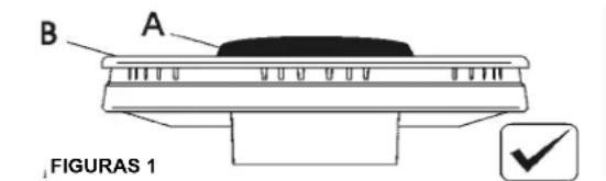
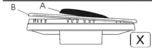
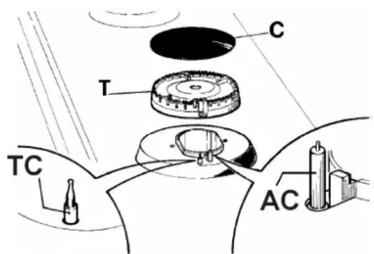
FIG.8/B
CLEANING
Before any cleaning operation, disconnect the appliance from the electric circuit.
ELECTRIC ELEMENT Hi-Light"
If you want to preserve the surface clean and bright, we recommend you to use a silicone conditioner.
The use of this conditioners, prior to jam-making, helps to protect the surface of the hob.
It is very important to clean the surface soon after every use, when the glass is still tepid.
Do not use metallic sponges, powder abrasives or corrosive sprays.
Depending on the dirty level we recommend:
- slights stains: it is enough the use of a moist clean rag.
- Marks of liquid, overflowed from the pot, can be removed using vinegar or lemon.
- Pay attention to not let fall sugar or element with sugar. In this case turn the switch off and clean the surface with hot water and a sponge.
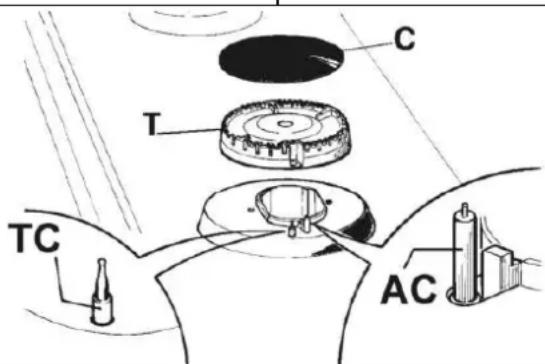
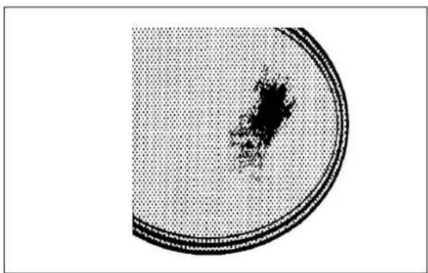
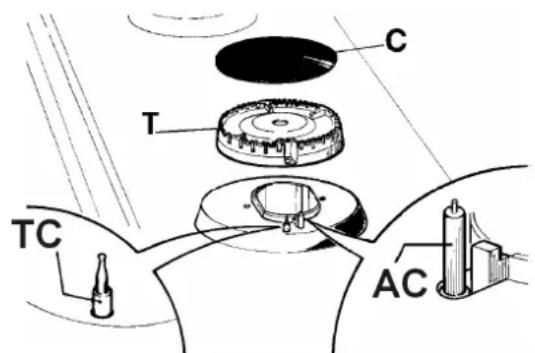
- After a period of time may appear metal reflex and scratches (fig. A) due to the wrong cleaning and the wrong use of the pots. The scratches are difficultly removable, but they do not compromise the good working of the hob.
- Don't use steam jets for the equipment cleaning.
For fully electric model

natural_image
Cross-sectional view of a circular container with a central dark spot and dotted pattern (no text or symbols)FIG. A

FIG. 9/A
INSTALLATION
TECHNICAL INFORMATION FOR THE INSTALLER
Installation, adjustments of controls and maintenance must only be carried out by a qualified engineer.
The appliance must be correctly installed in conformity with current law and the manufacturer's instructions.
Incorrect installation may cause damage to persons, animals or property for which the Manufacturer shall not be considered responsible.
During the life of the system, the automatic safety or regulating devices on the appliance may only be modified by the manufacturer or by his duly authorized dealer.
4) INSTALLING THE HOT PLATE
Check that the appliance is in a good condition after having removed the outer packaging and internal wrappings from around the various loose parts. In case of doubt, do not use the appliance and contact qualified personnel.
Never leave the packaging materials (cardboard, bags, polystyrene foam, nails, etc.) within children's reach since they could become potential sources of danger.
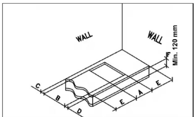
The measurements of the opening made in the top of the modular cabinet and into which the hot plate will be installed are indicated in either fig. 9-9/A.
Always comply with the measurements given for the hole into which the appliance will be recessed (see fig.9-9/A and the minimum distance shown in Fig. 10).
IMPORTANT!
A perfect installation, adjustment or transformation of the cook top to use other gases requires a QUALIFIED INSTALLER: a failure to follow this rule will void the warranty.
COMPLY WITH THE DIMENSIONS (mm)
| A B C D E | F | |||||
| (30) 30.1 1H-2H | 282 | 482 | 59 | 59 | 100 min | 120 min. |
| (30) 1-2 Gas | 282 | 482 | 59 | 59 | 300 min | 70 min. |
| (60) | 553 | 473 | 63.5 | 63.5 | 173.5 min. | 70 min. |
| (75) | 553 | 473 | 63.5 | 63.5 | 173.5 min. | 70 min. |
| (90) | 833 | 475 | 62.5 | 62.5 | 300 min. | 70 min. |
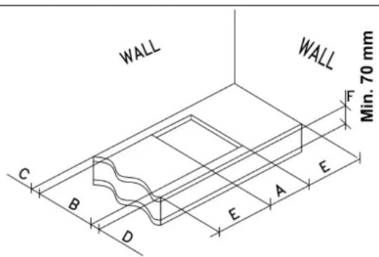
FIG. 9
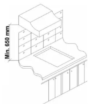
FIG. 10
INSTALLATION
The appliance belongs to class 3 and is therefore subject to all the provisions established by the provisions governing such appliances.
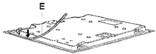
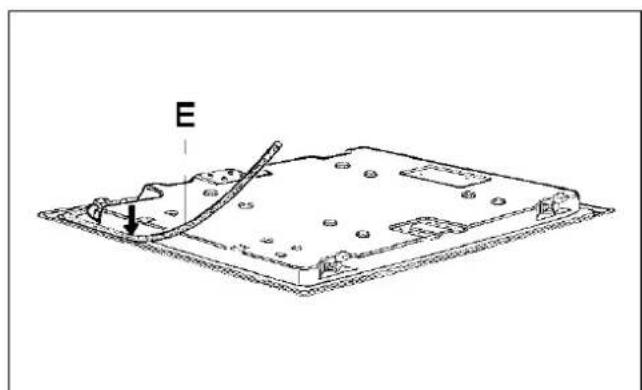
The hot plate has a special seal which prevents liquid from infiltrating into the cabinet. Strictly comply with the following instructions in order to correctly apply this seal:
- detach the seals from their backing, checking that the transparent protection still adheres to the seal itself.
- Overturn the hot plate and correctly position seal "E" (fig. 11) under the edge of the hot plate itself, so that the outer side of the seal perfectly matches the outer perimetral edge of the hot plate. The ends of the strips must fit together without overlapping.
- Evenly and securely fix the seal to the hot plate, pressing into place with the fingers and remove the strip of protective paper from the seal and set the plate into the hole made in the cabinet.
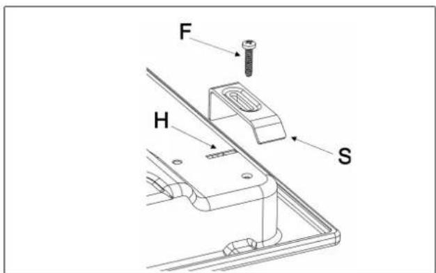
- Fix the hob with the proper brackets "S" and fit the prominent part into the porthole "H" on the bottom; turn the screw "F" until the bracket "S" stick on the top (fig. 12).
- In order to avoid accidental touch with the overheating bottom of the hob, during the working, is necessary to put a wooden insert, fixed by screws, at a minimum distance of 70 mm from the top (see fig. 9-9/A).
natural_image
Technical line drawing of a mechanical component with labeled point E and directional arrow (no text or symbols beyond label)FIG. 11
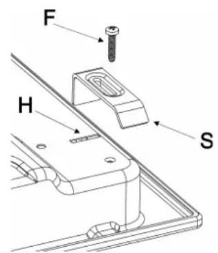
FIG. 12
INSTALLATION
IMPORTANT INSTALLATION SPECIFICATIONS
The installer should note that the appliance that side walls should be no higher than the hot plate itself. • Furthermore, the rear wall, the surfaces surrounding and adjacent to the appliance must be able to withstand an temperature of 90 °C.
The adhesive used to stick the plastic laminate to the cabinet must be able to withstand a temperature of not less than 150 °C otherwise the laminate could come unstuck.
The appliance must be installed in compliance with the provisions in force.
This appliance is not connected to a device able to dispose of the combustion fumes. It must therefore be connected in compliance with the above mentioned installation standards. Particular care should be paid to the following provisions governing ventilation and aeration.
6) ROOM VENTILATION
It is essential to ensure that the room in which the appliance is installed is permanently ventilated in order to allow the appliance itself to operate correctly. The necessary amount of air is that required for regular gas combustion and ventilation of the relative room, the volume of which must not be less than 20 m ^3 . Air must naturally flow through permanent openings in the walls of the room in question. These openings must vent the fumes outdoors and their section must be at least 100 cm ^2 (see fig. 3). Construction of the openings must ensure that the openings themselves may never be blocked. Indirect ventilation by air drawn from an adjacent room is also permitted, in strict compliance with the provisions in force.
7) LOCATION AND AERATION
Gas cooking appliances must always dispose of their combustion fumes through hoods. These must be connected to flues, chimneys or straight outside. If it is not possible to install a hood, an electric fan can be installed on a window or on a wall facing outside (see fig. 4). This must be activated at the same time as the appliance (see fig. 5), so long as the specifications in provisions in force are strictly complied with.
8) GAS CONNECTION
Before connecting the appliance, check that the values on the data label affixed to the underside of the hot plate correspond to those of the gas and electricity mains in the home.
A label on the appliance indicates the regulating conditions: type of gas and working pressure. Gas connection must comply with the pertinent standards and provisions in force.
When gas is supplied through ducts, the appliance must be connected to the gas supply system:
- with a rigid steel pipe. The joints of this pipe must consist of threaded fittings conforming to the de standards.
- With copper pipe. The joints of this pipe must consist of unions with mechanical seals.
- With seamless flexible stainless steel pipe. The length of this pipe must be 2 meters at most and the seals must comply with the standards.
When the gas is supplied by a bottle, the appliance must be fuelled by a pressure governor conforming to the provisions in force and must be connected:
- with a copper pipe. The joints of this pipe must consist of unions with mechanical seals.
- With seamless flexible stainless steel pipe. The length of this pipe must be 2 meters at most and the seals must comply with the standards. It is advisable to apply the special adapter to the flexible pipe. This is easily available from the shops and facilitates connection with the hose nipple of the pressure governor on the bottle.
- With rubber hose pipe in compliance with standards. The diameter of this hose pipe must be 8 mm and its length must be no less than 400 mm and no more than 1500 mm. It must be firmly fixed to the hose nipple by means of the safety clamp specified by standards.
WARNINGS:
remember that the gas inlet union on the appliance is a 1/2" gas conic male type in compliance with EN 10226 standards. Installation of stainless steel pipe and rubber hose pipe must ensure that it is never able to touch mobile parts of the built-in cabinet (eg. drawers). Furthermore, it must not pass through compartments that could be used for storage purposes.
When using a rubber hose pipe, it is essential to comply with the following instructions:
- no part of the pipe must be able to touch parts the temperature of 90 °C.
- The pipe must not be pulled or twisted, throttled or tightly bent.
- It must not come into contact with sharp edges or corners.
It must be easy to inspect the entire pipe length in order to check its state of wear.
- The pipe must be replaced within the date stamped on the pipe itself.
IMPORTANT:
The appliance complies with the provisions of the sub-regulations for European Directives:
- Regulation (EU) 2016/426.
INSTALLATION
IMPORTANT: the appliance must be installed following the manufacturer's instructions. The manufacturer will not be liable for injury to persons or animals or property damage caused by an incorrect installation.
The electrical connections of the appliance must be carried out in compliance with the provisions and standards in force.
Before connecting the appliance, check that:
- the voltage matches the value shown on the specification plate and the section of the wires of the electrical system can support the load, which is also indicated on the specification plate.
- The electrical capacity of the mains supply and current socket suit the maximum power rating of the appliance (consult the data label applied to the underside of the hot plate).
- The socket or system has an efficient earth connection in compliance with the provisions and standards in force. The manufacturer declines all responsibility for failing to comply with these provisions.
When the appliance is connected to the electricity mains by a socket:
- fit a standard plug "C" suited to the load indicated on the data label to the cable. Fit the wires following figure 13, taking care of respecting the following correspondences:
Letter L (live) = brown wire;
Letter N (neutral) = blue wire;
earth symbol ≡ green - yellow wire.
- The power supply cable must be positioned so that no part of it is able to reach an temperature of 90 °C.
- Never use reductions, adapters of shunts for connection since these could create false contacts and lead to dangerous overheating.
- The outlet must be accessible after the built-in.
- install an omnipolar circuit-breaker between the appliance and the electricity main. This circuit-breaker should be sized, in compliance with current installation regulations.
When the appliance is connected straight to the electricity main:
- Remember that the earth wire must not be interrupted by the circuit-breaker.
- For optimum safety, the electrical connection may also be protected by a high sensitivity differential circuit-breaker.
You are strongly advised to fix the relative yellow-green earth wire to an efficient earthing system.
Before performing any service on the electrical part of the appliance, it must absolutely be disconnected from the electrical network.
If the installation requires modifications to the home's electrical system or if the socket is incompatible with the appliance's plug, have changes or replacements performed by professionally-qualified person. In particular, this person must also make sure that the section of the wires of the socket is suitable for the power absorbed by the appliance.
WARNINGS:
all our products are conform with the European Norms and relative amendments. The product is therefore conform with the requirements of the European Directivesin force relating to:
- compatibility electromagnetic (EMC);
- electrical security (LVD);
- restriction of use of certain hazardous substances (RoHS);
- EcoDesign (ERP).
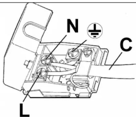
FIG. 13
ADJUSTMENTS
Always disconnect the appliance from the electricity main before making any adjustments.
All seals must be replaced by the technician at the end of any adjustments or regulations.
Our burners do not require primary air adjustment.
10) TAPS
"Reduced rate" adjustment
-Switch on the burner and turn the relative knob to the "Reduced rate" position (small flame fig. 1).
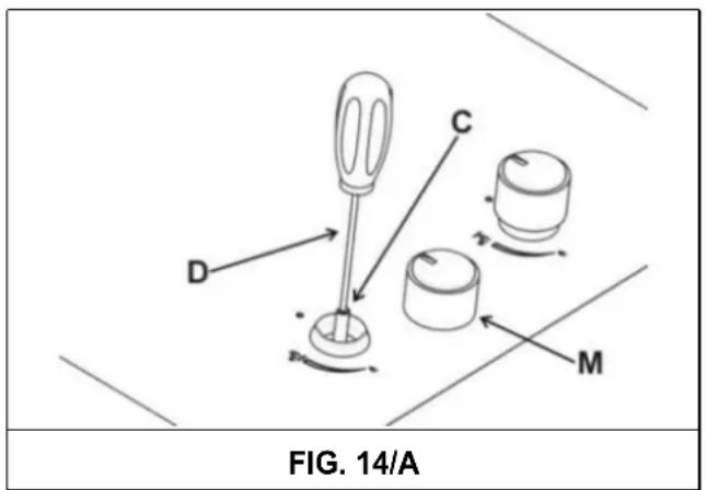
- Remove knob "M" (fig. 14 and 14/A) of the tap, which is simply pressed on to its rod. The by-pass for minimal rate regulation can be: beside the tap (fig. 14) or inside the shaft. In any case, to access to regulation, it can be done trough the insertion of a small screwdriver "D" beside the tap (fig. 14) or in the hole "C" inside the shaft of the tap
(fig 14/A). Turn the throttle screw to the right or left until the burner flame has been adequately regulated to the "Reduced rate" position.
The flame should not be too low: the lowest small flame should be continuous and steady. Re-assemble the several components.
It is understood that only burners operating with G20 gas should be subjected to the above mentioned adjustments. The screw must be fully locked when the burners operate with G30 or G31 (turn clockwise).
TAPS LUBRIFICATION
Should a tap being blocked, do not force and ask for Technical Assistance.
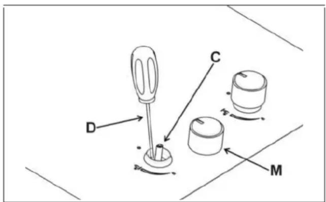
FIG. 14
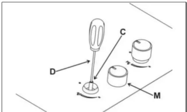
FIG. 14/A
CONVERSIONS
11) REPLACING THE INJECTORS
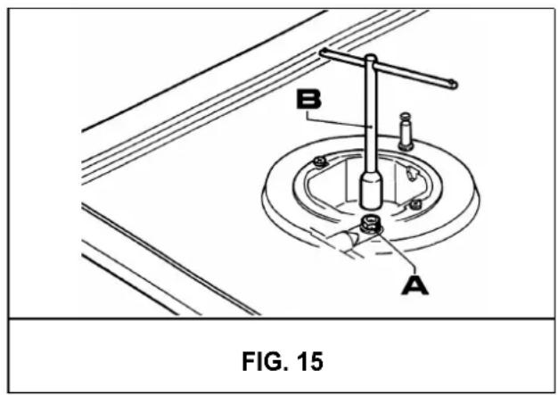
The burners can be adapted to different types of gas by mounting injectors suited to the type of gas in question. To do this, first remove the burner tops using a wrench "B". Now unscrew injector "A" (see fig. 15) and fit a injector corresponding to the utilized type of gas in its place.
It is advisable to strongly tighten the injector in place.
After the injectors have been replaced, the burners must be regulated as explained in
paragraphs 10. The technician must reset any seals on the regulating or pre-regulating devices. The envelope with the injectors and the labels can be included in the kit, or at disposal to the authorized customer Service Centre.
For the sake of convenience, the nominal rate table also lists the heat inputs of the burners, the diameter of the injectors and the working pressures of the various types of gas.
TABLE
| BURNERS | GAS | NORMAL PRESSURE mbar | NORMAL RATE | INJECTOR DIAMETER Max/100.5nm | NOMINAL HEAT INPUT (W) | ||||
| No. | DESCRIPTION | gr/h | Min. | Gas Burner* | |||||
| 1 | WOK Double crown | G 30 - BUTANE | 30 | 291 | 100 | 1800 | 4000 | 56,6 % | |
| G 31 - PROPANE | 30 | 286 | 100 | 1800 | 4000 | ||||
| G 20 - NATURAL | 20 | 381 | 150 H3 | 1800 | 4000 | ||||
| 2 | RAPID | G 30 - BUTANE | 30 | 218 | 85 | 800 | 3000 | 58,8 % | |
| G 31 - PROPANE | 30 | 214 | 85 | 800 | 3000 | ||||
| G 20 - NATURAL | 20 | 286 | 115 Y | 800 | 3000 | ||||
| 3 | SEMIRAPID | G 30 - BUTANE | 30 | 127 | 65 | 550 | 1750 | 58,6 % | |
| G 31 - PROPANE | 30 | 125 | 65 | 550 | 1750 | ||||
| G 20 - NATURAL | 20 | 167 | 98 Z | 550 | 1750 | ||||
| 4 | AUXILIARY | G 30 - BUTANE | 30 | 73 | 50 | 450 | 1000 | ---- | |
| G 31 - PROPANE | 30 | 71 | 50 | 450 | 1000 | ||||
| G 20 - NATURAL | 20 | 95 | 72 X | 450 | 1000 | ||||
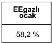
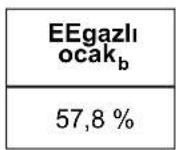
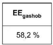
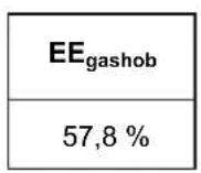
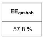
*In accordance with Regulation No. 66/2014 EU measures for the implementation of Directive 2009/125/EC, the performance (EEgas burner) was calculated according to EN 30-2-1 last review with the G20.
CONVERSIONS
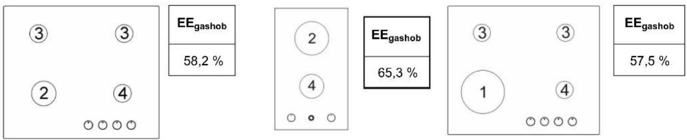
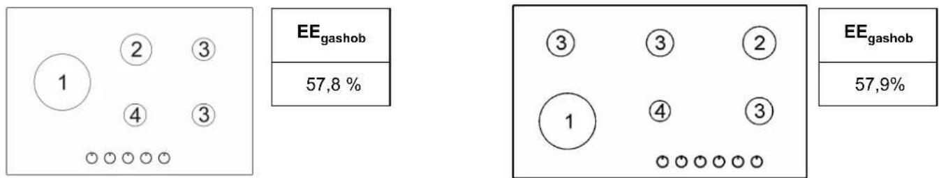
DISPOSITION OF THE BURNERS
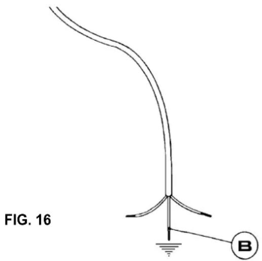
CABLE TYPES AND SECTIONS
| TYPE OF HOT PLATE | TYPE OF CABLE | SINGLE - PHASE POWER SUPPLY |
| Gas hot plate H05 RR - F / H07 RN | -F Section 3 x 0.75 mm | 2 |
| Mixed hot plate with 1 “Hi-Light” elements | H05 RR - F / H07 RN-F Section 3 x 1 mm | 2 |
| Mixed hot plate with most “Hi-Light” elements. + EFX 30 1H - EFX 30 2H | H05 RR - F / H07 RN-F Section 3 x 1.5 mm | 2 |
ATTENTION!!!
If the power supply cable is replaced, the installer should leave the ground wire (B) longer than the phase conductors (fig. 16) and comply with the recommendations given in paragraph 9.
POWER RATINGS OF THE ELECTRICAL COMPONENTS
| DENOMINATIONS | (cm) | POWER (W) | EC_electric cooking* (Wh/Kg) |
| Electric heating element “Hi-light” | 14,0 | 1200 | 187,0 |
| Electric heating element “Hi-light” | 18,0 | 1800 | 188,5 |
| Electric heating element ovale “Hi-Light” | 17,0 * 26,5 | 1400 / 2100 | 183,3 |
| Electric heating element “Rectang.”“Hi-Light” | 18,5 * 30,5 | 2400 | N.A |
*EC electric cooking: energy consumption per kg, calculated in accordance with Regulation (EU) 66/2014.
WARNING: MAINTENANCE MUST ONLY BE PERFORMED BY AUTHORISED PERSONS.
TECHNICAL DATA ON THE DATA LABEL
4 Burners (60)
CAT.: II2H3B/P
Σ Qn Gas Natural = 7.5 kW
Σ Qn GPL = 545 gr/h (G30)
Σ Qn GPL = 536 gr/h (G31)
TENSION = 220 - 240 V \~
FREQUENCY = 50-60 Hz
4 Burners (60) (WOK sx)
CAT.: II2H3B/P
Σ Qn Gas Natural = 8.5 kW
Σ Qn GPL = 618gr/h (G30)
2 Burners + 2 "Hi-light"
CAT.:II2H3B/P
G 30 - BUTANE = 30 mbar
G 31 - PROPANE = 30 mbar
G 20 - NATURAL = 20 mbar
Σ Qn Gas Natural = 4.0 kW
Σ Qn GPL = 291 gr/h(G30)
Σ Qn GPL = 286gr/h (G31)
TENSION = 220 - 240 V \~
FREQUENCY = 50/60 Hz
Potencia nominal Elem.E 3000 W
5 Burners (75) (WOK central)
CAT.: II2H3B/P
G 30 - BUTANE = 30 mbar
G 31 - PROPANE = 30 mbar
G 20 - NATURAL = 20 mbar
Σ Qn Gas Natural = 11.5 kW
Σ Qn GPL = 836 gr/h (G30)
Σ Qn GPL = 821 gr/h(G31)
TENSION = 220 - 240 V \~
FREQUENCY = 50-60 Hz
5 Burners (90) (WOK central)
CAT.: II2H3B/P
G 30 - BUTANE = 30 mbar
G 31 - PROPANE = 30 mbar
G 20 - NATURAL = 20 mbar
Σ Qn Gas Natural = 11.5 kW
Σ Qn GPL = 836 gr/h(G30)
Σ Qn GPL = 821 gr/h(G31)
TENSION = 220 - 240 V\~
FREQUENCY = 50-60 Hz
5 Burners (75-90) (WOK sx)
CAT.: II2H3B/P
G 30 - BUTANE = 30 mbar
G 31 - PROPANE = 30 mbar
G 20 - NATURAL = 20 mbar
Σ Qn Gas Natural = 11.5 kW
Σ Qn GPL = 836 gr/h (G30)
Σ Qn GPL = 821 gr/h(G31)
TENSION = 220 - 240 V\~
FREQUENCY = 50-60 Hz
4 Burners (90) (2 elem.Hi-light)
CAT.: II2H3B/P
G 30 - BUTANE = 30 mbar
G 31 - PROPANE = 30 mbar
G 20 - NATURAL = 20 mbar
Σ Qn Gas Natural = 7.5 kW
Σ Qn GPL = 545 gr/h(G30)
Σ Qn GPL = 536 gr/h (G31)
TENSION = 220 - 240 V \~
FREQUENCY = 50-60 Hz
Pot.Nom Elem.Hi-Light 3000 W
4 Burners (90) (1 elem. Oval Hi-light) WOK sx
CAT.: II2H3B/P
G 30 - BUTANE = 30 mbar
G 31 - PROPANE = 30 mbar
G 20 - NATURAL = 20 mbar
Σ Qn Gas Natural = 8.5 kW
Σ Qn GPL = 618 gr/h (G30)
6 Burners (90) WOK sx
CAT.: II2H3B/P
G 30 - BUTANE = 30 mbar
G 31 - PROPANE = 30 mbar
G 20 - NATURAL = 20 mbar
Σ Qn Gas Natural = 13.25 kW
Σ Qn GPL = 963 gr/h (G30)
Σ Qn GPL = 946 gr/h(G31)
TENSION = 220 - 240 V\~ FREQUENCY = 50-60 Hz
2 Burners (30)
CAT.:II2H3B/P
G 30 - BUTANE = 30 mbar
G 31 - PROPANE = 30 mbar
G 20 - NATURAL = 20 mbar
Σ Qn Gas Natural = 4.0 kW
Σ Qn GPL = 291 gr/h(G30)
Σ Qn GPL = 286gr/h (G31)
TENSION = 220 - 240 V\~
FREQUENCY = 50-60 Hz
1 Burners (30)
CAT.:II2H3B/P
G 30 - BUTANE = 30 mbar
G 31 - PROPANE = 30 mbar
G 20 - NATURAL = 20 mbar
Σ Qn Gas Natural = 4.0 kW
Σ Qn GPL = 291 gr/h(G30)
Σ Qn GPL = 286gr/h (G31)
TENSION = 220 - 240 V \~
FREQUENCY = 50-60 Hz
| Power Rating Together or without a timer | |
| TENSION | 220 - 240 V ~ |
| FREQUENCY | 50/60 Hz |
| Pot Tot. | 3000 W |
| Power Rating Together or without a timer | |
| TENSION | 220 - 240 V ~ |
| FREQUENCY | 50/60 Hz |
| Pot Tot. | 2400 W |
| Power Rating Together or without a timer | |
| TENSION | 220 - 240 V~ |
| FREQUENCY | 50/60 Hz |
| Pot Tot. | 2100-1400 W |
TECHNICAL DATA FOR THE APPLIANCE GAS REGULATION

In case of adaptation of the hob to another type of gas, operate as described in the directions for the and installation use and replace the label on the bottom with the one provided in the spare bag.
In case of failure or cut in the cable, please move away from the cable and do not touch it. Moreover the device must be unplugged and not switched on. Call the nearest authorized service center to fix the problem.
Keep the Warranty Certificate or the sheet of technical data with the Instructions Handbook during the appliance life. It contains important technical data.
TECHNICAL ASSISTENCE AND SPARE PARTS
Before leaving the factory, this appliance will have been tested and regulated by expert and specialized personnel in order to guarantee the best performances.
Any repairs or adjustments which may be subsequently required may only be carried out by qualified personnel with the utmost care and attention.
For this reason, always contact your Dealer or our nearest After Sales Service Center whenever repairs or adjustments are required, specifying the type of fault and the model of the appliance in your possession.
Please also note that genuine spare parts are only available from our After Sales Service Centers and authorized retail outlets.
The above data are printed on the data label put on the inferior part of the appliance and on the packing label.
The above informations give to the technical assistant the possibility to get fit spare parts and a heaven-sent intervention. We suggest to fill the table below.
MARK:
MODEL:
SERIES:
This appliance is marked according to the European directive 2002/96/EC on Waste Electrical and Electronic Equipment (WEEE).
This guideline is the frame of a European-wide validity of return and recycling on Waste Electrical and Electronic Equipment.
EFX 70.1 5G AI AL DR CI LEFT EFX 70.1 5G AI AL DR CI
EFX 60.1 4G AI AL DR CI EFX 60.1 4G AI AL CI
EFX 60.1 2G 2H AI AL
EFX 90.1 5G AI AL DR CI EFX 90.1 5G AI AL DR CI LEFT
EFX 90.1 4G 1H AI AL DR EFX 90.1 4G 2H AI AL
EFX 90.1 6G AI AL DR CI LEFT EFX 30.1 1G AI AL DR CI
EFX 30.1 2H - EFX 30 2H-T EFX 30.1 1H - EFX 30 1H-T
EFX 30.1 2G AI AL CI

natural_image
3D rendering of a gas stove with four fans and three pistons on a metal base (no text or symbols visible)
RO
natural_image
3D rendering of a gas stove burner with black and metallic blades (no text or symbols visible)
UTILIZARE
1) ARZATOARE
natural_image
Line drawings of two cooking pots with heating elements, no text or symbols presentFIG. 2

UTILIZARE
NOTA:
FIG. 3 FIG. 4 FIG. 5
UTILIZARE
2) PORNIREA PLITELOR ELECTRICE "Hi-Ligts"
| Zone n° 17 | ∅ 14,0 | “Hi-light” | 1200 W | |
| Zone n° 18 | ∅ 18,0 | “Hi-light” | 1800 W | |
| Zone n° 24 | ∅ 17,0*26,5 | “Hi-light” | 1400/2100 W | |
| Zone n° 25 | ∅ 18,5*30,5 | “Hi-light” | 2400 W “Rectangular” |
natural_image
Simple line drawing of a pot with liquid and two handles, placed on a surface (no text or symbols)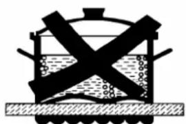
natural_image
Simple line drawing of a container with crossed arms and liquid, placed on a textured surface (no text or symbols)
natural_image
Silhouette of a mechanical device with gears and shafts, resting on a textured surface (no text or symbols)
natural_image
Simple line drawing of a cooking pot with steam rising and crossed out (no text or symbols)FIG. 7
CURATARE
ATENTIE:
inainte de a efectua orice operatie de curatare, deconectati aparatul de la reteaua de alimentare cu gaz si electrica.
3) SUPRAFATA DE LUCRU
natural_image
Line drawing of a hand using a tool to clean or inspect a circular mechanical component (no text or symbols)FIG. 8 FIG. 8/A
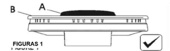
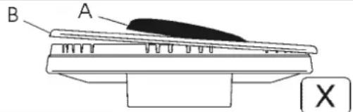

FIG. 8/B
RO
CURATARE
For fully electric model
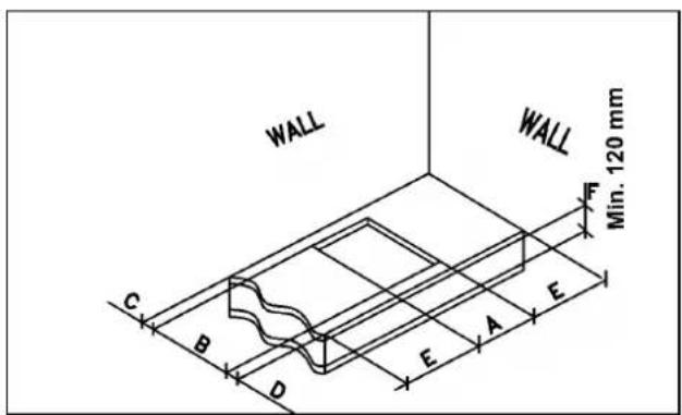
FIG. 9/A
natural_image
Cross-sectional view of a circular object with a dark irregular spot on its surface, no visible text or symbols.FIG. A
INSTALARE
DATE TEHNICE DESTINATE INSTALATORILOR
Instalarea, toate reglajele, transformarile si intretinerea descrise vor trebui executate numai de personal calificat.
MODIFICARI

natural_image
Simple diagram with four circles and numbered circles, no text or symbols present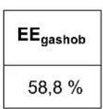
natural_image
Diagram of a curved pipe or tube with a base and labeled point B, no text or symbols present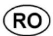
DATE TEHNICE NOTATE PE ETICHETA
4 ARZATOARE (60)
CAT.: II2H3B/P
G 30 - BUTAN = 30 mbar
G 31 - PROPAN = 30 mbar
G 20 - NATURAL = 20 mbar
Σ Qn Gaz Natural = 7.5 kW
Σ Qn GPL = 545gr/h (G30)
Σ Qn GPL = 536 gr/h(G31)
Σ Qn Gaz Natural = 8.5 kW
Σ Qn GPL = 618gr/h (G30)
Σ Qn GPL = 607gr/h (G31)
Σ Qn Gaz Natural = 4.0 kW
Σ Qn GPL = 291gr/h (G30)
Σ Qn GPL = 286gr/h (G31)
Σ Qn GazNatural = 11.5 kW
Σ Qn GPL = 836 gr/h(G30)
Σ Qn GPL = 821 gr/h(G31)
Σ Qn Gaz Natural = 11.5 kW
Σ Qn GPL = 836 gr/h(G30)
Σ Qn GPL = 821 gr/h(G31)
Σ Qn Gaz Natural = 11.5 kW
Σ Qn GPL = 836 gr/h(G30)
Σ Qn GPL = 821 gr/h(G31)
Σ Qn Gaz Natural = 7.5 kW
Σ Qn GPL = 545 gr/h(G30)
4 ARZATOARE (90) (1 elem. Oval Hi-light) WOK sx
CAT.: II2H3B/P
G 30 - BUTAN = 30 mbar
G 31 - PROPAN = 30mbar
G 20 - NATURAL = 20 mbar
Σ Qn Gaz Natural = 8.5 kW
Σ Qn GPL = 618 gr/h(G30)
Σ Qn Gaz Natural = 13.25 kW
Σ Qn GPL = 963 gr/h(G30)
Σ Qn GPL = 946 gr/h(G31)
S Qn Gaz Natural = 4.0 kW
S Qn GPL = 291gr/h (G30)
S Qn GPL = 286gr/h (G31)
S Qn Gaz Natural = 4.0 kW
S Qn GPL = 291gr/h (G30)
S Qn GPL = 286gr/h (G31)
EFX 70.1 5G AI AL DR CI LEFT
EFX 70.1 5G AI AL DR CI
EFX 60.1 4G AI AL DR CI
EFX 60.1 4G AI AL CI
EFX 60.1 2G 2H AI AL
EFX 90.1 5G AI AL DR CI
EFX 90.1 5G AI AL DR CI LEFT
EFX 90.1 4G 1H AI AL DR
EFX 90.1 4G 2H AI AL
EFX 90.1 6G AI AL DR CI LEFT
EFX 30.1 1G AI AL DR CI
EFX 30.1 2H - EFX 30 2H-T
EFX 30.1 1H - EFX 30 1H-T
EFX 30.1 2G AI AL CI

natural_image
3D rendering of a gas stove with four fans and three stillers on a metal platform (no text or symbols visible)
CZ
natural_image
3D rendering of a gas stove burner with black outlines and a central rotary knob, labeled 'OBR. A' (no other text or symbols)
POUŽÍVÁNÍ
1) HOŘÁKY
natural_image
Simple line drawing of a circle with scattered symbols and a small square, no text or labels present.natural_image
Line drawing of a cooking pot with a wavy base and two handles (no text or symbols)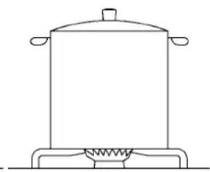
natural_image
Line drawing of a cooking pot on a heating element (no text or symbols)OBR. 2
CZ
POUŽÍVÁNÍ
Poznámka:
natural_image
Simple line drawing of a cooking pot with liquid and two handles (no text or symbols)
natural_image
Simple line drawing of a container with an X-shaped handle and liquid, resting on a textured surface (no text or symbols)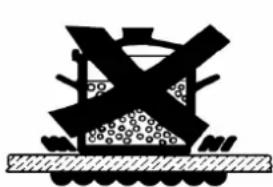
natural_image
Silhouette of a ship or vessel with broken hulls and floating objects on a textured base (no text or symbols)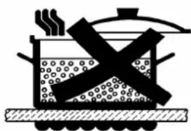
natural_image
Simple line drawing of a steam locomotive with smoke and fuel, no text or symbols presentOBR. 7
CZ
ČIŠTĚNÍ
Upozornění:
natural_image
Line drawing of a hand using a tool to clean or inspect a circular component (no text or symbols)OBR. 8 OBR. 8/A

OBR. 8/B
CZ
ČIŠTĚNÍ
For fully electric model

natural_image
Cross-sectional view of a circular object with a dark irregular spot on its surface, no visible text or symbols.OBR. A
OBR. 9/A

INSTALACE
DÜLEŽITÉ PŘEDPISY PRO INSTALACI

natural_image
Simple diagram with four circles and numbered circles, no text or symbols present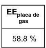
natural_image
Pure diagram of a curved pipe or tube with a base and a labeled point B, no text or symbols present.2 HOŘÁKY + 2 "Hi-light"
KAT.: II2H3B/P
G 30 - BUTAN = 30 mbar
G 31 - PROPAN = 30 mbar
G 20 - ZEMNI = 20 mbar
Σ Qn Gaz ZEMNÍ = 4.0 kW
Σ Qn GPL = 291 gr/h(G30)
Σ Qn GPL = 286 gr/h (G31)
Příkon = 220 - 240 V \~
Frekvence = 50-60 Hz
Put. Nom. El. Rating 3000 W
5 HOŘÁKY (75) (WOK CENTRÁLNÍ)
KAT.: II2H3B/P
G 30 - BUTAN = 30 mbar
G 31 - PROPAN = 30 mbar
G 20 - ZEMNÍ = 20 mbar
Σ Qn Gaz ZEMNÍ = 11.5 kW
Σ Qn GPL = 836 gr/h (G30)
Σ Qn GPL = 821 gr/h(G31)
Příkon = 220 - 240 V \~
Frekvence = 50-60 Hz
5 HOŘÁKY (90) (WOK CENTRÁLNÍ)
KAT.: II2H3B/P
G 30 - BUTAN = 30 mbar
G 31 - PROPAN = 30 mbar
G 20 - ZEMNÍ = 20 mbar
Σ Qn Gaz ZEMNÍ = 11.5 kW
Σ Qn GPL = 836 gr/h(G30)
Σ Qn GPL = 821 gr/h(G31)
Příkon = 220 - 240 V \~
Frekvence = 50-60 Hz
5 HOŘÁKY (75-90) (WOK sx)
KAT.: II2H3B/P
G 30 - BUTAN = 30 mbar
G 31 - PROPAN = 30 mbar
G 20 - ZEMNÍ = 20 mbar
Σ Qn Gaz ZEMNÍ = 11.5 kW
Σ Qn GPL = 836 gr/h(G30)
Σ Qn GPL = 821 gr/h(G31)
Příkon = 220 - 240 V \~
Frekvence = 50-60 Hz
4 HOŘÁKY (90) (2 elem.Hi-light)
KAT.: II2H3B/P
G 30 - BUTAN= 30 mbar
G 31 - PROPAN = 30 mbar
G 20 - ZEMNÍ = 20 mbar
Σ Qn Gaz ZEMNÍ = 7.5 kW
Σ Qn GPL = 545 gr/h(G30)
Σ Qn GPL = 536 gr/h(G31)
Příkon = 220 - 240 V \~
Frekvence = 50-60 Hz
Put. Nom. El. Rating3000 W
4 HOŘÁKY (90)
(1 elem. Oval Hi-light) WOK sx
KAT.: II2H3B/P
G 30 - BUTAN = 30 mbar
G 31 - PROPAN = 30mbar
G 20 - ZEMNÍ = 20 mbar
Σ Qn Gaz ZEMNÍ = 8.5 kW
Σ Qn GPL = 618 gr/h(G30)
EFX 70.1 5G AI AL DR CI LEFT
EFX 70.1 5G AI AL DR CI
EFX 60.1 4G AI AL DR CI
EFX 60.1 4G AI AL CI
EFX 60.1 2G 2H AI AL
EFX 90.1 5G AI AL DR CI
EFX 90.1 5G AI AL DR CI LEFT
EFX 90.1 4G 1H AI AL DR
EFX 90.1 4G 2H AI AL
EFX 90.1 6G AI AL DR CI LEFT
EFX 30.1 1G AI AL DR CI
EFX 30.1 2H - EFX 30 2H-T
EFX 30.1 1H - EFX 30 1H-T
EFX 30.1 2G AI AL CI
natural_image
3D rendering of a gas stove with four flanges and control knobs (no text or symbols visible)
SK
natural_image
3D rendering of a gas stove burner with black and metallic blades (no text or symbols visible)
POUŽÍVANIE
1) HORÁKY
natural_image
Simple line drawing of a pot with liquid and two handles, placed on a surface (no text or symbols)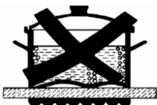
natural_image
Simple line drawing of a container with liquid and two crossed arms, no text or symbols present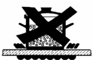
natural_image
Silhouette of a construction site with excavator and pile foundation (no text or symbols)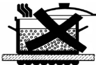
natural_image
Illustration of a cooking pot with steam rising and crossed out by a crossed-out X (no text or symbols)OBR. 7
SK
ČISTENIE
POZOR:
natural_image
Hand using a tool to clean or inspect a circular component (no text or symbols visible)OBR. 8 OBR. 8/A
OBR. 8/B
SK
ČISTENIE
natural_image
Cross-sectional view of a circular object with a dark irregular spot on its surface, surrounded by a dotted pattern (no text or symbols)OBR. A
SK
INŠTALÁCIA
TECHNIČKÉ INFORMÁCIE URČENE INSTALATEROM
For fully electric model
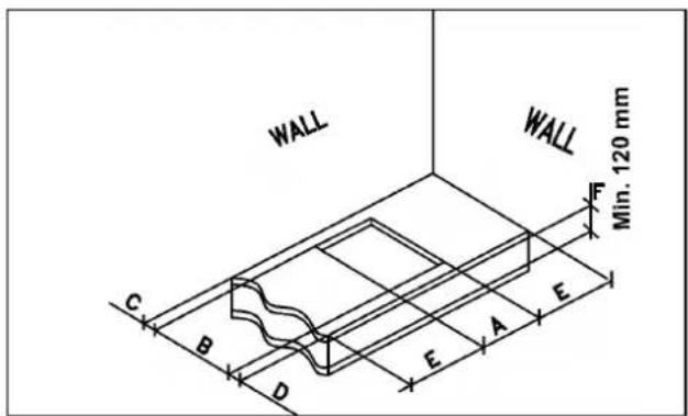
FIG. 9/A
OBR. 11
OBR. 12

INŠTALÁCIA
POKyny DOLEŽITÉ PRE INSTALÁCIU
pie
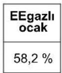
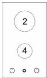
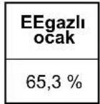
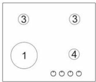
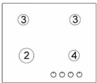
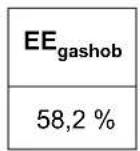
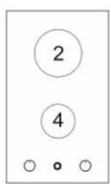
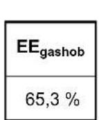
| Chart | Label | Value (%) | |---|---|---| | Left Chart | ③ | 57.5 | | Left Chart | ① | 57.5 | | Right Chart | EE_gashob | 58.2 | | Right Chart | ③ | 58.2 | | Right Chart | ④ | 58.2 | | Right Chart | : ○○○○○○○○ | 58.2 |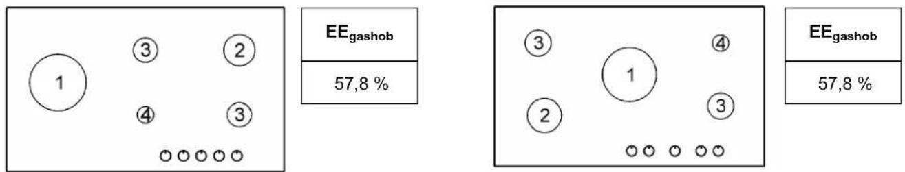
other
| Label | Value (%) | |---|---| | ③ | 58,2 | | ② | 65,3 | | ④ | 57,5 | The chart displays a grid-like layout with numbered circles and circles representing categories. The first circle is labeled 'EE_gashob', while the other four are labeled 'EE_gashob'. The values in parentheses are explicitly labeled as '3' above the circle.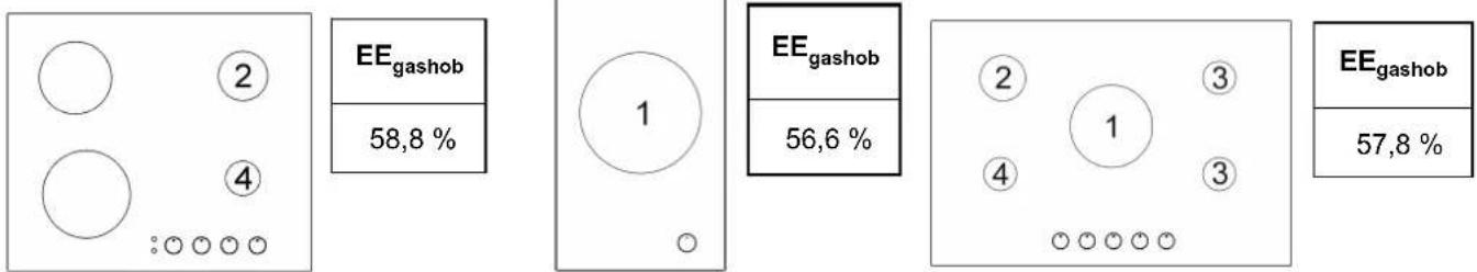

ÚDRŽBA
TYPY A PRIEREZY NAPÁJACÍCH KÁBLOV
| TYP VARNEJ DOSKY TYP KÁBLA JEDNOFÁZOVÉ NAPÁJANIE | ||
| Plynová doska H05 RR - F / H07 RN - F 3 x 0.75 mm | 2 | |
| Jeden elektrický prvok “Hi-Light” H05 RR - F / H07 RN - F 3 x 1 mm | 2 | |
| Väčšina elektrický výrobky “Hi-Light” H05 RR - F / H07 RN - F 3 x 1.5 mm | 2 | |
| Väčšina elektrický výrobky “Hi-Light” EFX 30 1H - EFX 30 2H | H05 RR - F / H07 RN - F 3 x 1.5 mm | 2 |
POZOR!!!
natural_image
Simple line drawing of a curved pipe or tube with a base and a labeled point B, no text or symbols present.SK
TECHNICKÉ ÚDAJE UVÁDZANÉ NA ŠTÍTKU
4 HORÁKY(60)
KAT.: II2H3B/P
G30 - Bután = 30 mbar
G31 - Propán = 30 mbar
G20 - Zemni = 20 mbar
Σ Qn Gaz Zemni= 7.5 kW
Σ Qn GPL = 545 gr/h (G30)
Σ Qn GPL = 536 gr/h(G31)
Příkon = 220 - 240 V \~
Frekvence = 50-60 Hz
4 HORÁKY (60)
(WOK sx)
KAT.: II2H3B/P
G30 - Bután = 30 mbar
G31 - Propán = 30 mbar
G20 - Zemni = 20 mbar
Σ Qn Gaz Zemni = 8.5 kW
Σ Qn GPL = 618 gr/h (G30)
Σ Qn Gaz Zemni = 4.0 kW
Σ Qn GPL = 291 gr/h(G30)
Σ Qn Gaz Zemni = 11.5 kW
Σ Qn GPL = 836 gr/h(G30)
Σ Qn GPL = 821 gr/h(G31)
Příkon = 220 - 240 V \~
Frekvence = 50-60 Hz
5 HORÁKY (90) (WOK CENTRÁLNÍ)
KAT.: II2H3B/P
G30 - Bután = 30 mbar
G31 - Propán = 30 mbar
G20 - Zemni = 20 mbar
Σ Qn Gaz Zemni = 11.5 kW
Σ Qn GPL = 836 gr/h(G30)
Σ Qn GPL = 821 gr/h(G31)
Příkon = 220 - 240 V \~
Frekvence = 50-60 Hz
5 HORÁKY (75-90) (WOK sx)
KAT.: II2H3B/P
G30 - Bután = 30 mbar
G31 - Propán = 30 mbar
G20 - Zemni = 20 mbar
Σ Qn Gaz Zemni= 11.5 kW
Σ Qn GPL = 836 gr/h(G30)
Σ Qn GPL = 821 gr/h(G31)
Příkon = 220 - 240 V \~
Frekvence = 50-60 Hz
4 HORÁKY(90)
(2 elem.Hi-light)
KAT.: II2H3B/P
G30 - Bután = 30 mbar
G31 - Propán = 30 mbar
G20 - Zemni = 20 mbar
Σ Qn Gaz Zemni = 7.5 kW
Σ Qn GPL = 545 gr/h(G30)
Σ Qn GPL = 536 gr/h(G31)
Příkon = 220 - 240 V \~
Frekvence = 50-60 Hz
Put. Nom. El. Rating3000 W
4 HORÁKY(90)
(1 elem. Oval Hi-light) WOK sx
KAT.: II2H3B/P
G30 - Bután = 30 mbar
G31 - Propán = 30 mbar
G20 - Zemni = 20 mbar
Σ Qn Gaz Zemni = 8.5 kW
Σ Qn GPL = 618 gr/h(G30)
Σ Qn Gaz Zemni = 13.25 kW
Σ Qn GPL = 963 gr/h(G30)
Σ Qn GPL = 946 gr/h(G31)
Příkon = 220 - 240 V \~
Frekvence = 50-60 Hz
TECHNICKÉ ÚDAJE UVÁDZANÉ NA ŠTÍTKU
2 HORÁKY (30)
KAT.: II2H3B/P
G30 - Bután = 30 mbar
G31 - Propán = 30 mbar
G20 - Zemni = 20 mbar
Σ Qn Gaz Zemni = 4.0 kW
Σ Qn GPL = 291 gr/h(G30)
Σ Qn Gaz Zemni = 4.0 kW
Σ Qn GPL = 291 gr/h(G30)
natural_image
World map silhouette showing continents and countries (no text or labels)www.teka.com
COD. 04042E3 - 06.02.2019 - Rev. 1
- TEMİZLEME
- ÖNEMLİ:
- MONTAJ
- GAZLI OCAKLAR (60) İKİ TAÇ WOK
- GAZLI + 2 plakalar (60)
- LÜOCAKLAR (ORTA GÖZÜ WOK) (90)
- LÜOCAKLAR (Çok Hizli ürkek) (75-90)
- LÜOCAKLAR (90) (2 plakalar)
- LÜOCAKLAR (90) (1 plakalar oval) ORTA GÖZÜ WOK
- LÜOCAKLAR (90) ORTA GÖZÜ WOK
- Instructions for the installation and advice for the maintenance. Instructions Manual
- DESCRIPTION OF THE HOT PLATES
- USE
- 1) BURNERS
- - manual ignition
- - Automatic electrical ignition
- - Lighting burners equipped with flame failure device
- HOW TO USE THE BURNERS
- WARNINGS:
- WARNINGS AND ADVICE FOR THE USER:
- TIMER
- 2) SWITCHING ON THE ELECTRIC PLATES "Hi-Ligts"
- ACTIVATION OF THE DOUBLE ZONE
- How to use the cooking zones
- TABLE
- CAUTION:
- CLEANING
- IMPORTANT:
- 3) HOT PLATE
- ELECTRIC ELEMENT Hi-Light"
- INSTALLATION
- TECHNICAL INFORMATION FOR THE INSTALLER
- 4) INSTALLING THE HOT PLATE
- IMPORTANT!
- IMPORTANT INSTALLATION SPECIFICATIONS
- 6) ROOM VENTILATION
- 7) LOCATION AND AERATION
- 8) GAS CONNECTION
- The electrical connections of the appliance must be carried out in compliance with the provisions and standards in force.
- When the appliance is connected to the electricity mains by a socket:
- When the appliance is connected straight to the electricity main:
- ADJUSTMENTS
- 10) TAPS
- TAPS LUBRIFICATION
- CONVERSIONS
- 11) REPLACING THE INJECTORS
- ATTENTION!!!
- TECHNICAL DATA ON THE DATA LABEL
- Burners (60)
- Burners (60) (WOK sx)
- Burners + 2 "Hi-light"
- Burners (75) (WOK central)
- Burners (90) (WOK central)
- Burners (75-90) (WOK sx)
- Burners (90) (2 elem.Hi-light)
- Burners (90) (1 elem. Oval Hi-light) WOK sx
- Burners (90) WOK sx
- Burners (30)
- Burners (30)
- TECHNICAL DATA FOR THE APPLIANCE GAS REGULATION
- TECHNICAL ASSISTENCE AND SPARE PARTS
- UTILIZARE
- 1) ARZATOARE
- NOTA:
- 2) PORNIREA PLITELOR ELECTRICE "Hi-Ligts"
- CURATARE
- ATENTIE:
- 3) SUPRAFATA DE LUCRU
- INSTALARE
- DATE TEHNICE DESTINATE INSTALATORILOR
- MODIFICARI
- DATE TEHNICE NOTATE PE ETICHETA
- ARZATOARE (60)
- ARZATOARE (90) (1 elem. Oval Hi-light) WOK sx
- POUŽÍVÁNÍ
- 1) HOŘÁKY
- Poznámka:
- ČIŠTĚNÍ
- Upozornění:
- INSTALACE
- DÜLEŽITÉ PŘEDPISY PRO INSTALACI
- HOŘÁKY + 2 "Hi-light"
- HOŘÁKY (75) (WOK CENTRÁLNÍ)
- HOŘÁKY (90) (WOK CENTRÁLNÍ)
- HOŘÁKY (75-90) (WOK sx)
- HOŘÁKY (90) (2 elem.Hi-light)
- HOŘÁKY (90)
- (1 elem. Oval Hi-light) WOK sx
- POUŽÍVANIE
- 1) HORÁKY
- ČISTENIE
- POZOR:
- INŠTALÁCIA
- TECHNIČKÉ INFORMÁCIE URČENE INSTALATEROM
- POKyny DOLEŽITÉ PRE INSTALÁCIU
- ÚDRŽBA
- POZOR!!!
- TECHNICKÉ ÚDAJE UVÁDZANÉ NA ŠTÍTKU
- HORÁKY(60)
- HORÁKY (60)
- (WOK sx)
- HORÁKY (90) (WOK CENTRÁLNÍ)
- HORÁKY (75-90) (WOK sx)
- HORÁKY(90)
- (2 elem.Hi-light)
- HORÁKY (30)
Brand : TEKA
Model : EFX 32300 IH
Category : Cooker