
SWS 16600 - Weather Station SENCOR - Free user manual and instructions
Find the device manual for free SWS 16600 SENCOR in PDF.


| Product Type | Smart Weather Station with 7-in-1 Professional Sensor and Hygro-thermo Sensor |
| Model | SWS 16600 |
| Brand | Sencor |
| Console Dimensions (W x H x D) | 215 x 176.5 x 27 mm (8.5 x 6.9 x 1.1 in) |
| Console Weight | 599 g (with battery, without adapter) |
| Wireless 7-in-1 Sensor Dimensions (W x H x D) | 390 x 217 x 165 mm (15.4 x 8.5 x 6.5 in) without pole and stand |
| Wireless 7-in-1 Sensor Weight | 831 g (with pole and stand, without batteries) |
| Console Power | DC 5V, 1A adapter (included), backup CR2032 button cell |
| Wireless 7-in-1 Sensor Power | 3 x AA 1.5V batteries (non-rechargeable, lithium recommended for cold climates) |
| Wireless Hygro-thermo Sensor Power | 2 x AA 1.5V batteries (alkaline recommended) |
| Measured Parameters | Indoor and outdoor temperature & humidity, wind speed & direction, rainfall, UV index, light intensity, barometric pressure, feels like, dew point |
| Wireless Communication | 868 MHz (depending on country), range up to 150 m (492 ft) line of sight |
| Wi-Fi Standard | 802.11 b/g/n, 2.4 GHz |
| App Compatibility | Tuya Smart or Smart Life app (Android and iOS) |
| Console Display | Colorful LCD with backlight (Hi/Lo/Auto) |
| Additional Optional Sensors Supported | Up to 3 thermo-hygro sensors, 3 water leak sensors, 1 PM2.5/PM10, 1 CO2, 1 HCHO/VOC, 1 CO sensor |
| Weather Forecast | 12-24 hour prediction based on barometric pressure, accuracy 70-75% |
| Alarm Function | Time alarm with snooze and customizable weather alerts (high/low limits for multiple parameters) |
| History Graph | Graphs for pressure, temperature, humidity, rainfall; time periods from 24h to 24 days |
| Maintenance | Replace batteries; clean rain collector, UV sensor, and radiation shield; replace wind vane/cup if needed |
| Safety Notes | Not for medical use; keep away from children; avoid shock, dust, extreme temperatures; use only specified adapter; properly dispose of batteries |
Frequently Asked Questions - SWS 16600 SENCOR
User questions about SWS 16600 SENCOR
0 question about this device. Answer the ones you know or ask your own.
Ask a new question about this device
Download the instructions for your Weather Station in PDF format for free! Find your manual SWS 16600 - SENCOR and take your electronic device back in hand. On this page are published all the documents necessary for the use of your device. SWS 16600 by SENCOR.
USER MANUAL SWS 16600 SENCOR
natural_image
Exterior view of a weather monitoring station with a digital display showing real-time readings (no readable text or symbols)EN ■User Manual Smart Weather Station with 7-in-1 Professional Sensor & Hygro-thermo Sensor
Quick start guide....4
Pre-installation....5
Checkout....5
Site selection 5
Getting started 5
Wireless 7-in-1 sensor....5
Install wind vane 6
Wireless hygro-thermo sensor....10
Synchronizing additional sensor(s) (optional)....11
Recommendation for best wireless communication 13
Power up the console 14
Synchronizing wireless 7-in-1 sensor and hygro-thermo sensor.... 15
Data clearing....15
Display console function and operation.... 16
Screen display 16
Console overview 16
Console function and operation.... 17
About the local time 17
Console settings 18
Setting alarm time....18
View sunrise / sunset time....19
View year....19
Moon phase 20
Wireless sensor signal receiving 20
Trend indicator 20
View outdoor temperature and humidity 20
View indoor, optional thermo-hygro and leak channels 21
Barometric pressure 21
Wind....24
Rain 26
Calibration....31
Other functions 32
Backlight 32
Maintenance 32
Wireless 7-in-1 sensor array maintenance 32
Troubleshoot....33
Specifications 33
Console....33
Wireless 7-IN-1 sensor 35
Wireless thermo-hygrometer sensor....35
ABOUT THIS USER'S MANUAL

This symbol represents a warning. To ensure safe use, always adhere to the instructions described in this documentation.

This symbol is followed by a user's tip.
PRECAUTION & WARNING
! i
- Keeping and reading the "User manual" is highly recommended. The manufacturer and supplier cannot accept any responsibility for any incorrect readings, export data lost and any consequences that occur should an inaccurate reading take place.
- This instruction manual contains useful information on the proper use and care of this product. Please read this manual through to fully understand and enjoy its features, and keep it handy for future use.
– Images shown in this manual may differ from the actual display.
– The contents of this manual may not be reproduced without the permission of the manufacturer. - Technical specifications and user manual contents for this product are subject to change without notice.
- This product is not to be used for medical purposes or for public information
- Do not subject the unit to excessive force, shock, dust, temperature or humidity.
- Do not cover the ventilation holes with any items such as newspapers, curtains etc.
- Do not immerse the unit in water. If you spill liquid over it, dry it immediately with a soft, lint-free cloth.
- Do not clean the unit with abrasive or corrosive materials.
- Do not tamper with the unit's internal components. This invalidates the warranty.
- Placement of this product on certain types of wood may result in damage to its finishing for which manufacturer will not be responsible. Consult the furniture manufacturer's care instructions for information.
- Only use attachments / accessories specified by the manufacturer.
- This product is intended for use only with the adaptor provided: Manufacturer: DONGGUAN SHIJIE HUAXU ELECTRONICS FACTORY, Model: HX075-0501000-AG-001.
- The socket-outlet shall be installed near the equipment and easily be accessible.
- When replacement parts are required, be sure the service technician uses replacement parts specified by the manufacturer that have the same characteristics as the original parts. Unauthorized substitutions may result in fire, electric shock, or other hazards.
- This product is not a toy. Keep out of reach of children.
- The console is intended to be used only indoors.
- Place the console at least 20cm from nearby persons.
- This device is only suitable for mounting at height < 2m.
- When disposing of this product, ensure it is collected separately for special treatment.
- CAUTION! Risk of explosion if battery is replaced by an incorrect type.
- Battery cannot be subjected to high or low extreme temperatures, low air pressure at high altitude during use, storage or transportation, if not, it may result in an explosion or the leakage of flammable liquid or gas.
- Disposal of a battery into fire or a hot oven, or mechanically crushing or cutting of a battery, that can result in an explosion.
- Do not ingest the battery, Chemical Burn Hazard.
- This product contains a coin/button cell battery. If the coin/button cell battery is swallowed, it can cause severe internal burns in just 2 hours and can lead to death.
- Keep new and used batteries away from children.
-
If the battery compartment does not close securely, stop using the product and keep it away from children.
-
If you think batteries might have been allowed or placed inside any part of the body, seek immediate medical attention.
- Only use fresh batteries. Do not mix new and old batteries.
- Dispose of used batteries according to the instructions.
- Replacement of a battery with an incorrect type that can result in an explosion or the leakage of flammable liquid or gas.
INTRODUCTION
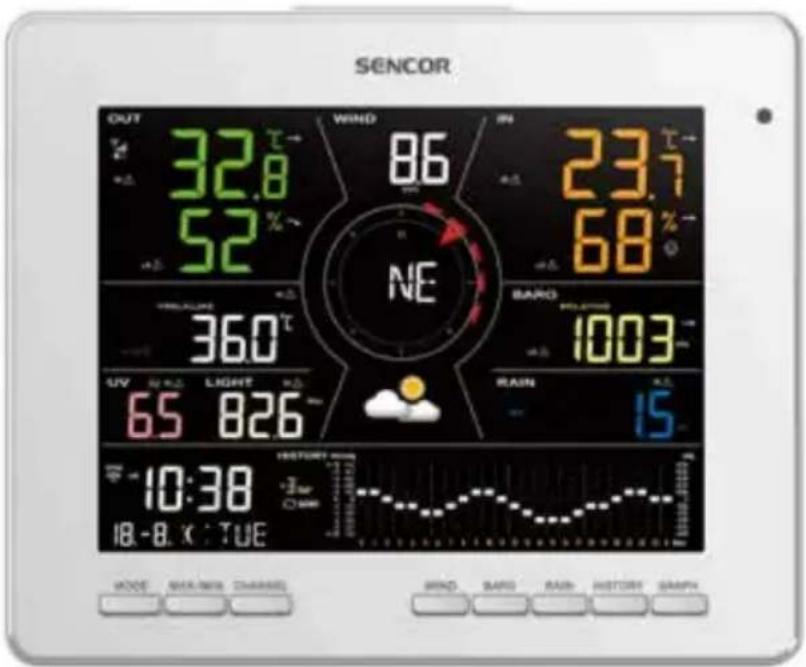
Thank you for selecting Tuya smart weather station. The console has built-in WI-FI module and through its smart system is compatible with Tuya IoT platform. You can view the IN / OUT temperature and humidity, wind, rain, UV and light intensity live data on the console, it can also display the other optional wireless thermo-hygro, leakage and air quality sensor(s) to monitor your home's comfort condition and air quality level. Through the Smart Life app, you can also check history records and trigger your Tuya devices in anywhere. The colorful LCD display shows the readings clearly and tidy, this system is a truly IoT system for you and your home.
QUICK START GUIDE
The following quick start guide provides the necessary steps to install and operate the weather station, and upload to the internet, along with references to the pertinent sections.
| Step Description | |
| 1 Power | up the wireless 7-in-1 sensor |
| 2 Power | up the console and pair with sensor |
PRE-INSTALLATION
CHECKOUT
Before permanently install your weather station, we recommend the user to operate the weather station at a location which is easy to access to. This will allow you to get familiar with the weather station functions and calibration procedures, to ensure proper operation before installing it permanently.
SITE SELECTION
Before installing the sensor array, please consider the followings:
- Batteries must be changed about every 2 to 2.5 years
- Avoid radiant heat reflected from any adjacent buildings and structures. Ideally, the sensor array should be installed at 1.5m (5') from any building, structure, ground or roof top.
- Choose an area of open space in direct sunlight without any obstruction of rain, wind, and sunlight.
- Transmission range between sensor array and console could reach a distance of 150m (or 450 feet) at line of sight, providing there are no interfering obstacles in between or nearby such as trees, towers, or high voltage line. Check the reception signal quality to ensure good reception.
- Household appliance such as fridge, lighting, dimmers may pose Electro-magnetic interference (EMI), while Radio Frequency Interference (RFI) from devices operating in the same frequency range may cause signal intermittent. Choose a location at least 1-2 meter (3-5 feet) away from these interference sources to ensure best reception.
GETTING STARTED
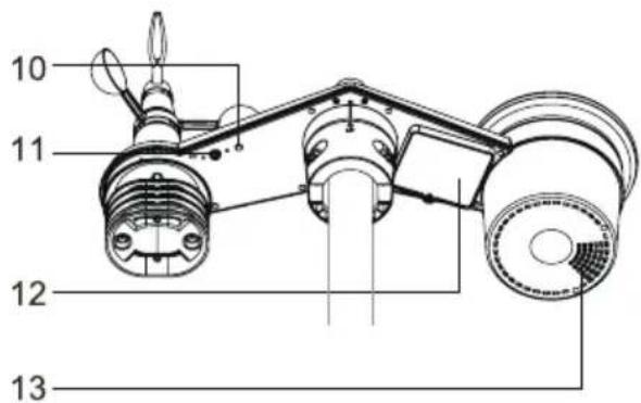
WIRELESS 7-IN-1 SENSOR
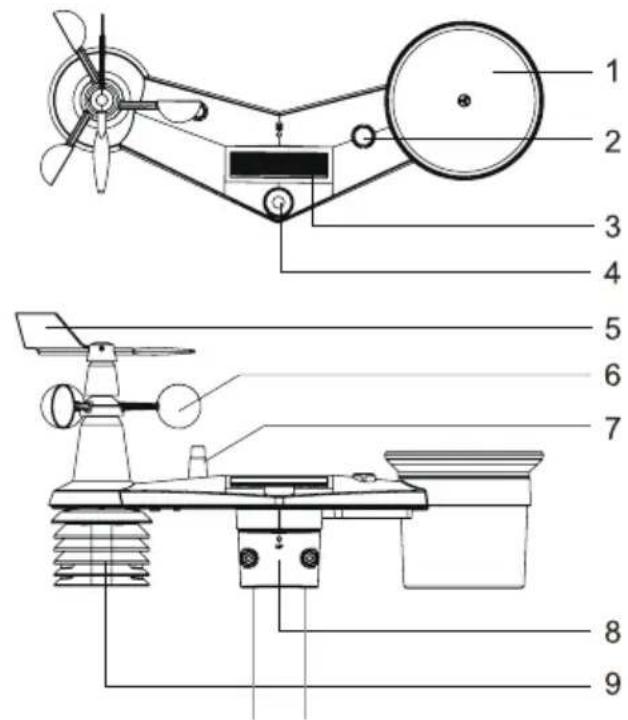
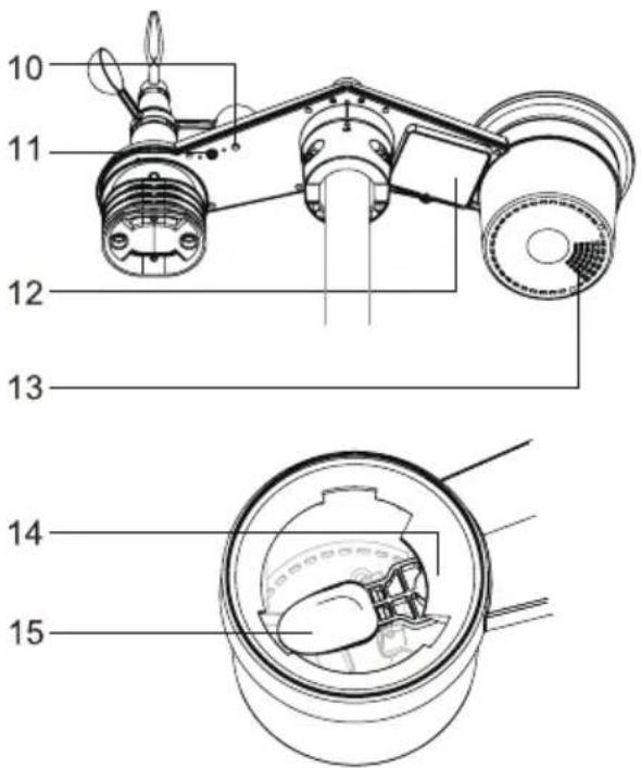
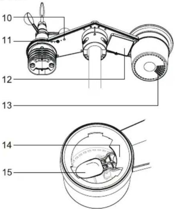
- Rain collector
- Balance indicator
- Solar panel
- UVI / light sensor
- Wind vane
- Wind cups
- Antenna
- Mounting clamp
- Radiation shield and thermo-hygro sensor
- Red LED indicator
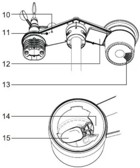
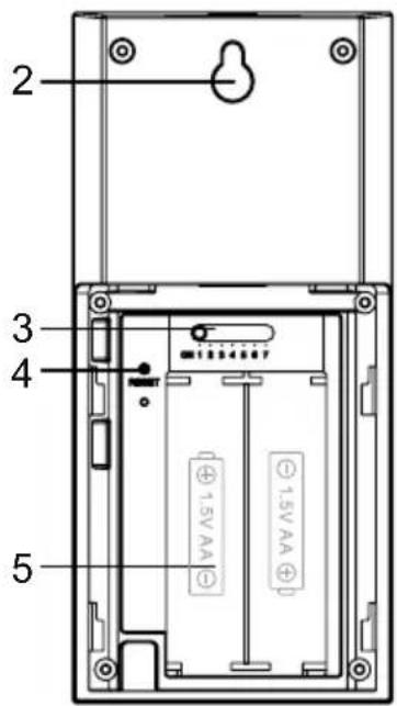
- [RESET]
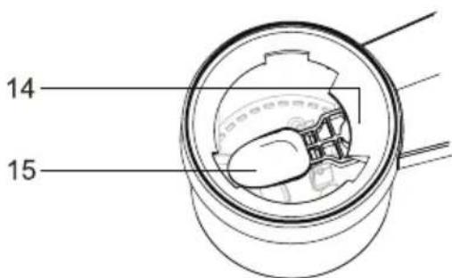
- Battery door
- Drain holes
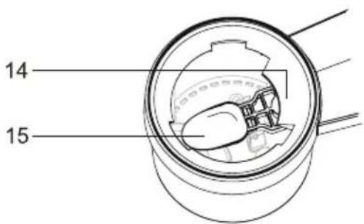
- Rain sensor
- Tipping bucket
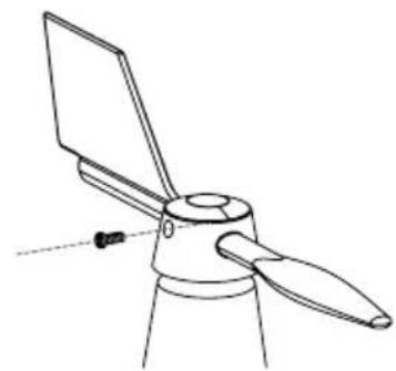
INSTALL WIND VANE
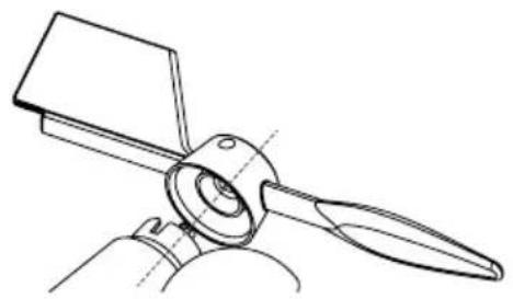
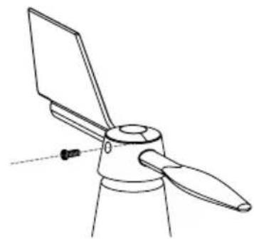
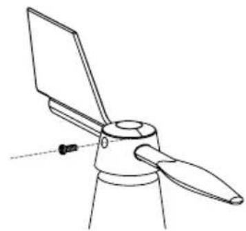
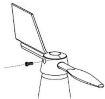
With reference to photo below, (Step 1) locate and align the flat are on the wind vane shaft to the flat surface on the wind vane and push the vane onto the shaft. (Step 2) tighten the set screw with a precision screwdriver.
natural_image
Technical line drawing of a propeller or fan assembly (no text or symbols)Step 1 Step 2
natural_image
Line drawing of a propeller with three blades and a handle, no text or symbols presentInstall rain gauge funnel
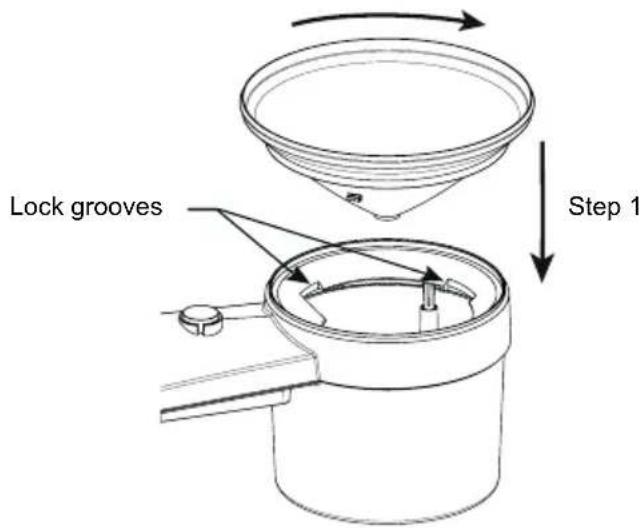
Install the rain gauge funnel and rotate clockwise to lock the funnel to the sensor array Step 2
Install batteries
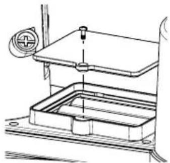
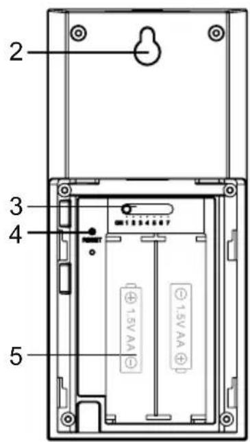
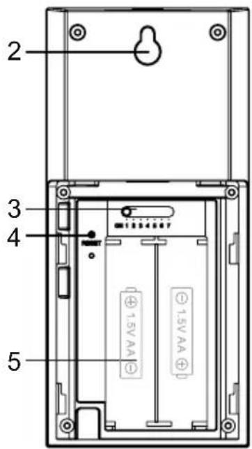
Unscrew the battery door at bottom of unit. Insert the 3 AA batteries (non-rechargeable) according to the +/- polarity indicated. The red LED indicator on the back of the sensor array will turn on, and then begin flashing every 12 seconds.
natural_image
Technical line drawing of a mechanical assembly with a valve and base plate (no text or symbols)NOTE:
We recommend using non-rechargeable Lithium AA batteries for cold weather climate, but normally Alkaline batteries are sufficient for use in most weather condition.
Sensor array installation
Mounting kit set
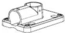 | 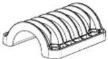 | 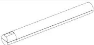 |
| 1. Pole mounting stand × 1 2. Mounting clamp × 1 3. Plastic pole × 1 | ||
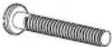 |  |  |
| 4. screws × 4 5. Hex nuts × 4 6. Flat washers × 4 | ||
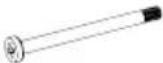 |  |  |
| 7. screw × 1 8. Hex nut × 1 9. Rubber pad × 4 | ||
Plastic Mounting installation
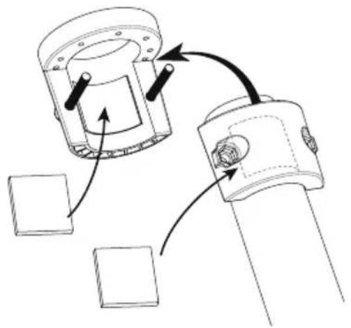
- Fasten the plastic pole onto your fix pole with mounting base, clamp, washers, screws and nuts. Following below 1a, 1b, 1c sequences:
1a. Insert the plastic pole into the hole of the mounting stand, and then secure it with the screw and nut.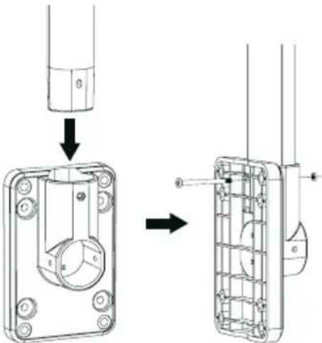 | 1c. Fasten the mounting stand and clamp together onto a fix pole with 4 long screws and nuts.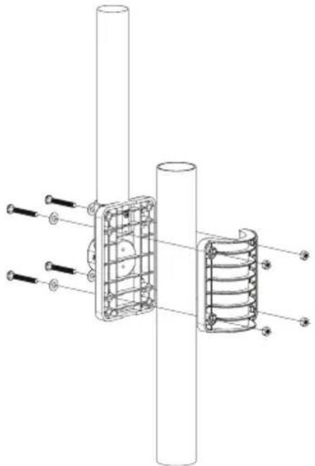 |
1b. Apply 2 rubber pads on the mounting clamp.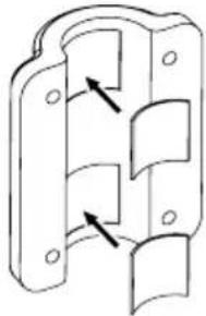 |
-
Apply 2 rubber pads on the inner sides of the mounting base and clamp of the sensor-array, and loosely fasten them together.
-
Place the sensor-array over the mounting pole and align it to North direction before fastening the screws.
natural_image
Technical line drawing of a mechanical assembly with arrows indicating motion or force direction (no text or symbols)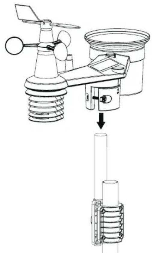
natural_image
Technical diagram of an air condition sensor assembly with a vertical tube inserted into a housing (no text or labels)NOTE:
- Any metal object can attract lightning strikes, including your sensor-array mounting pole. Never install sensor-array in stormy days.
- If you want to install a sensor-array on a house or building, consult a licensed electrical engineer to ensure proper grounding. Direct lightning impact on a metal pole can damage or destroy your home.
- Installing the sensor at high location may result in personal injury or death. Perform as many initial inspections and operations as possible on the ground and in buildings or houses. Only install the sensor-array on clear, dry days.
- Ensure the sensor-array installation place is stable and no vibration.
Direction alignment
Install the wireless 7-in-1 sensor in an open location with no obstructions above and around the sensor for accurate rain and wind measurement.
Locate the North (N) marker on top of the 7-in-1 sensor and align the marker to point North upon final installation with a compass or GPS. Tighten the mounting bracket around a 30 to 40 mm diameter pole (not included) using two screw and nuts provided.
Use the bubble level on the 7-in-1 sensor to make sure the sensor is completely level for proper measurement of rainfall.
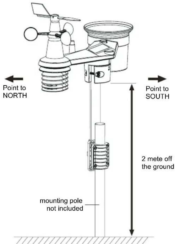
Pointing the wireless 7-in-1 sensor to south
The outdoor 7-in-1 sensor is calibrated to point to North for the maximum accuracy. However, for the user's convenience (e.g. users in the Southern hemisphere), it is possible to use the sensor with the wind vane pointing to South.
- Install the 7-in-1 wireless sensor with its wind meter end pointing to South.
- Select "S" in set hemisphere step.
- Follow the setup procedure to confirm and exit.
NOTE:
Changing the hemisphere setting will automatically switch the direction of the moon phase on the display.
WIRELESS HYGRO-THERMO SENSOR
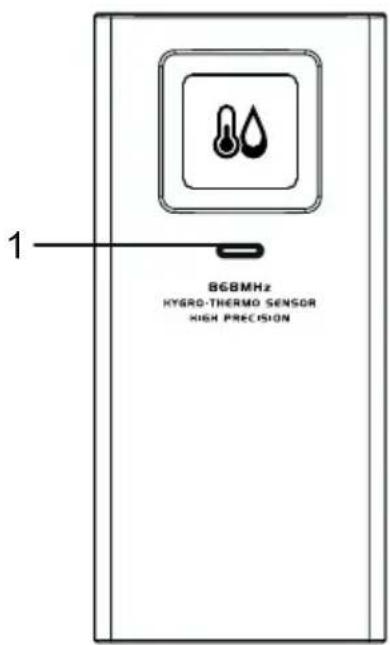
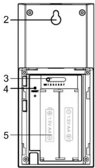
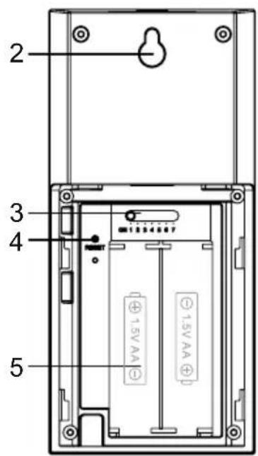
- Transmission status LED
- Wall mounting holder
-
[CHANNEL] slide switch to assign the sensor to Channel 1,2,3,4,5,6 or 7
-
[RESET] key
- Battery compartment
Install wireless hygro-thermo sensor
- Remove the battery door of the sensor.
- Use the channel slide switch to set the channel number for the sensor (e.g. Channel 1)
- Insert 2 × AA size batteries into the battery compartment according to the polarity marked on the battery compartment, and close the battery door.
- The sensor is in synchronization mode, and can be registered to the console within the next few minutes. The transmission status LED will begin to flash every 1 minute.
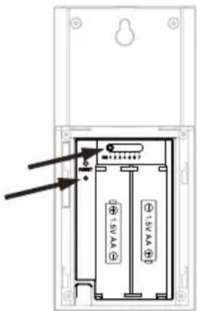
NOTE:
- If you need to re-assign the sensor channel, slide the channel slide switch to the new channel position and press [RESET] key on the sensor for the new channel number to be effective.
- Avoid placing the sensors in direct sunlight, rain or snow.
- To avoid the sensor/s and console pairing failure during new console setup, please power up the sensor(s) first, and then press [SENSOR/WiFi] key on the main unit.
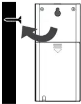
Placing the wireless thermo-hygro sensor
Place a screw on the wall that you wish to hang the sensor on. Hang the sensor onto the screw by the wall mounting holder. You can also place the sensor on a table by itself.
natural_image
Diagram of a door with a scroll wheel and directional arrow indicating rotation (no text or symbols)SYNCHRONIZING ADDITIONAL SENSOR(S) (OPTIONAL)
The console can support 4 different air quality sensors, up to 3 wireless thermo-hygro sensors and up to 3 water leak sensors. Please contact your local retailer for details of difference sensors.
Some of these sensors are multi-channel. Before inserting the batteries, set the channel number if channel slide switch is located at back of sensors (inside battery compartment). For their operations please refer to the manuals that come with the products.
Thermo-hygro and water leak optional sensors
| No. of sensor support Description Image | ||
| Up to 3 sensors | Thermo-hygrometer sensor | 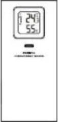 |
| High precision thermo-hygrometer sensor | 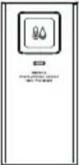 | |
| Soil moisture and temperature sensor | 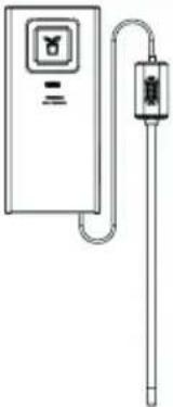 | |
| Pool sensor | 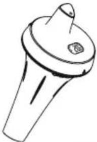 | |
| Up to 3 sensors Water leak sensor | 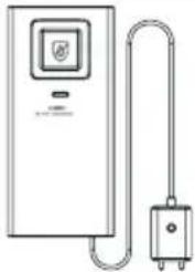 | |
Air quality Optional sensors
| No. of sensor support Description Image | ||
| 1 sensor PM2.5 / 10 sensor | 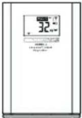 | |
| 1 sensor CO | _2 sensor | 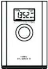 |
| 1 sensor HCHO with VOC sensor | 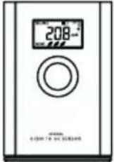 | |
| 1 sensor CO sensor | 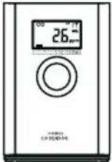 | |
NOTE:
For air quality sensors pairing, you can assign the sensors in any channel. The console support to display one channel of each of air quality sensor.
RECOMMENDATION FOR BEST WIRELESS COMMUNICATION
Effective wireless communication is susceptible to noise interference in the environment, and distance and barriers between the sensor transmitter and the console.
- Electromagnetic interference (EMI) – these may be generated by machinery, appliances, lighting, dimmers and computers, etc. So please keep your console 1 or 2 meters away from these items.
- Radio-frequency interference (RFI) – if you have other devices operating on 868 / 915 / 917 MHz, you might experience communication intermittent. Please re-located your transmitter or console to avoid signal intermittent problem.
- Distance. Path loss occurs naturally with distance. This device is rated to 150m (450 feet) by line of sight (in interference free environment and without barriers). However, typically you will get 30m (100 feet) maximum in real life installation, which includes passing through barriers.
- Barriers. Radio signal are blocked by metal barriers such as aluminum cladding. Please align the sensor array and console to get them in clear line of sight through window if you have metal cladding.
The table below show a typical level of reduction in signal strength each time the signal passed through these building materials.
| Materials Signal strength reduction | |
| Glass (untreated) 10 ~ 20% | |
| Wood 10 ~ 30% | |
| Plasterboard / drywall 20 ~ 40% | |
| Brick 30 ~ 50% | |
| Foil insulation 60 ~ 70% | |
| Concrete wall 80 ~ 90% | |
| Aluminum siding 100% | |
| Metal wall 100% | |
Remarks: RF signal reduction for reference
POWER UP THE CONSOLE
Install backup battery and power up
- Backup battery provides power to the console to retain clock time and date, max/min records and calibration value.
| Step 1 Step 2 Step 3 | ||
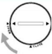 | 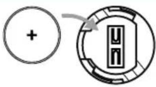 | 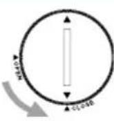 |
| Remove the console battery door with coin | Insert a new CR2032 button cell battery | Replace the battery door. |
NOTE:
- The backup battery can backup: Time & Date and MAX/MIN records.
- The built-in memory can backup: calibration value and connection settings.
-
Please always remove the backup battery if the device is not going to be used for a while.
Please keep in mind that even when the device is not in use, certain settings, such as the clock, calibration and records in its memory, will still drain the backup battery. -
Plug in the power adapter to power up the console.
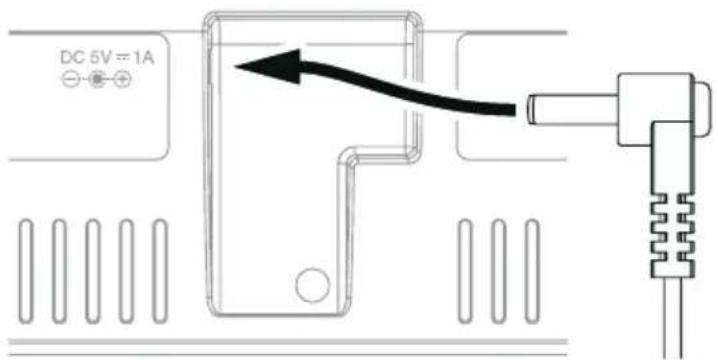
Setup the console
- Once the console is power up, all the segments of the LCD will be shown.
- The console will automatically enter AP mode and sensor synchronization mode automatically.
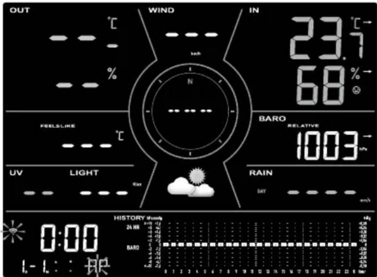
If no display appears when power up the console. You can press [RESET] by using a pointed object. If this process still not work, you can remove the backup battery and unplug the adaptor then re-power up the console again.
SYNCHRONIZING WIRELESS 7-IN-1 SENSOR AND HYGRO-THERMO SENSOR
Immediately after power up the console, while still in synchronization mode, the 7-in-1 sensor and hygro-thermo sensor can be paired to the console automatically (as indicated by the flashing antenna). User may also manually restart the synchronization mode by pressing the [SENSOR / WI-FI]. Once they are paired up, the sensor signal strength indicator and weather reading will appear on your console display.
DATA CLEARING
During installation of the wireless 7-in-1 sensor, the sensors were likely to be triggered, resulting in erroneous rainfall and wind measurements. After the installation, user may clear out all the erroneous data from the display console. Simply press the [RESET] once to re-start the console.
DISPLAY CONSOLE FUNCTION AND OPERATION
SCREEN DISPLAY
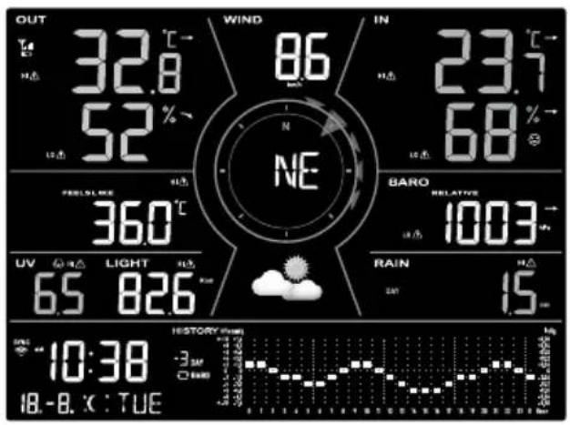
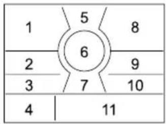
- Outdoor temperature & humidity
- Weather index and optional air quality sensor(s) readings (e.g. PM2.5 /10, CO₂, HCHO + VOC, CO)
- UV index & light intensity (SUN)
-
Time Calendar, moon phase & sunrise / Sunset
-
Wind speed
- Wind direction, Beaufort & Gust
- Weather forecast
- Indoor / CH temperature & humidity
- Barometer
- Rainfall & rain rate
- Weather history graph
CONSOLE OVERVIEW
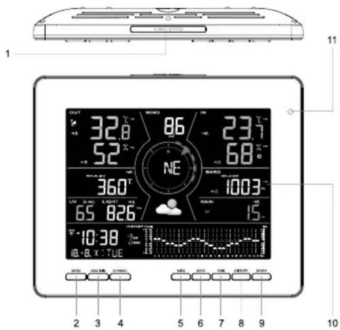
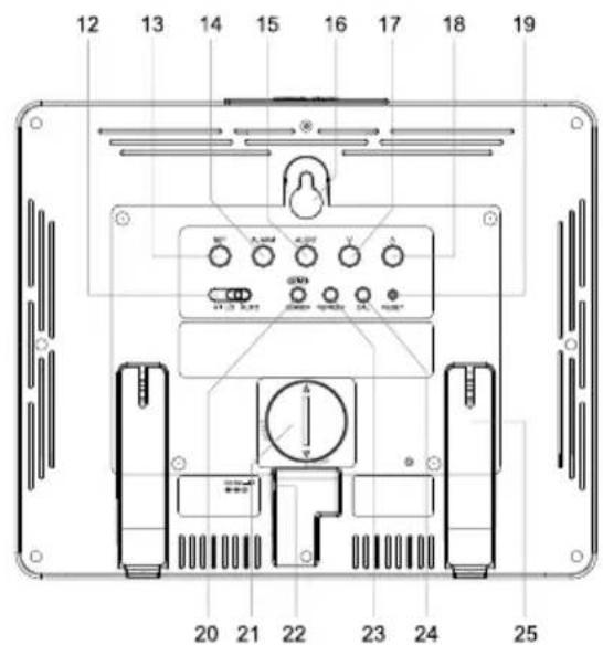
| No. | Key / Part name Description | |
| 1 | ALARM/SNOOZE Press to stop alarm sound. | |
| 2 | MODE | Press to switch between feels like, dew point and optional air quality sensor readings. |
| 3 | MAX / MIN | Press to switch between past 24 hours maximum and minimum weather data records. |
| 4 | CHANNEL Press to switch between indoor and channels readings. | |
| No. | Key / Part name Description | |
| 5 | WIND | Press to switch between wind direction, wind gust, 10 minutes gust and Beaufort scale. |
| 6 | BARO Switch between relative | and absolute air pressure reading. |
| 7 | RAIN Press to switch between | rain rate and rainfall. |
| 8 | HISTORY | Press to switch between different time period of current graph. |
| 9 | GRAPH Press to switch between | en different history graph. |
| 10 | Display screen | |
| 11 | Light sensor for backlight | |
| 12 | BACKLIGHT Slide to select the backlight in Hi / Lo / Auto mode. | |
| 13 | SET | Press to show sunrise / sunset time.Hold to enter time and date settings. |
| 14 | ALARM | Press to view alarm time.Hold to enter alarm settings. |
| 15 | ALERT | Press to view alert settings.Hold to enter alert settings. |
| 16 | Wall mounting hole | |
| 17 | V | Decrease the value in setting. |
| 18 | ^ | Increase the value in setting. |
| 19 | RESET | Press to reset the console.Hold 6 seconds to factory reset the console. |
| 20 | SENSOR / WI-FI | Press to start sensor synchronization (pairing).Hold 6 seconds to enter AP mode, vice versa. |
| 21 | Battery compartment | |
| 22 | Power jack | |
| 23 | REFRESH Press to update the upload data and time synchronization. | |
| 24 | CAL Press to enter the calibration mode. | |
| 25 | Table stand | |
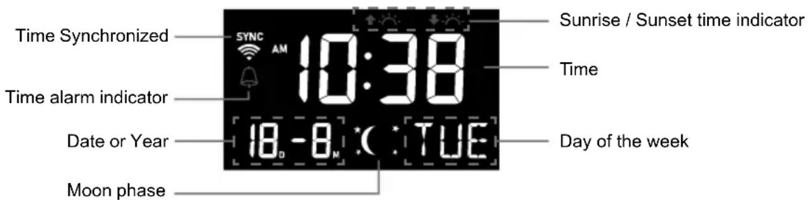
CONSOLE FUNCTION AND OPERATION
The console will automatically synchronize to your local time after successfully connected to app. You can manually set the date and time if device off-line.
CONSOLE SETTINGS
Setting mode
The setting mode can set the time, date, unit of measure and other functions.
Press and hold [SET] for 2 seconds to enter the setting Mode. In setting mode, press [SET] to proceed to the next setting step. Press [V] or [A] to change the value. Press and hold the key for quick-adjust. Please refer to following setting procedures below:
| Step Mode Setting procedure | |
| [SET] +2s 12/24 hour format Press | [V] or [A] to select 12 or 24 hour format. |
| [SET] Time Press [ | V] or [A] to adjust the minute / hour. |
| [SET] Year Press [ | V] or [A] to adjust the year. |
| [SET] Date Press [ | V] or [A] to adjust the day / month. |
| [SET] M-D D-M | Press [V] or [A] to select „Month / Day“ or „Day / Month“ display format. |
| [SET] Time sync ON/OFF | Press [V] or [A] to enable or disable time sync function If you want to set the time manually, you should set time sync OFF. |
| [SET] Hemisphere | Press [V] or [A] to select North / South hemisphere for moon phase. |
| [SET] Weekday Language Press | [V] or [A] to select weekday display language. |
| [SET] Temperature unit Press [ | V] or [A] to change the unit between °C and °F |
| [SET] HCHO unit Press [ | V] or [A] to change the unit between ppb and μg/m3 |
| [SET] CO2unit | Press [V] or [A] to change the unit between ppm and μg/m3 |
| [SET] CO unit | Press [V] or [A] to change the unit between ppm and μg/m3 |
| [SET] Wind speed unit | Press [V] or [A] to change the unit between m/s, km/h, knots and mph |
| [SET] Air pressure unit | Press [V] or [A] to change the unit between hPa, mmHg and inHg |
| [SET] Light intensity unit | Press [V] or [A] to change the unit between Klux, W/m2and Kfc |
| [SET] Rain unit Press [ | V] or [A] to change the unit between mm and inch |
| [SET] Exit setting |
NOTE:
- Console will exit setting mode automatically, if no operation after 60 seconds.
- Press and hold [SET] for 2 seconds to exit the setting mode at any time.
SETTING ALARM TIME
- In normal time mode, press and hold [ALARM] for 2 seconds until the alarm time digit flashes to enter alarm time setting mode.
- Press [V] or [A] to change the value. Press and hold the key for quick-adjust.
- Press [ALARM] to save and exit the setting.
NOTE:
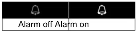
- When you turn on the time alarm the 🔔” icon will display on the LCD.
- The alarm function will turn on automatically once you set the alarm time.
View and activate alarm time
- In normal mode, press [ALARM] to show the alarm time for 5 seconds.
- When the alarm time displays, press [ALARM] again to activate the alarm function.
Suspend the time alarm
You can suspend the alarm sound by following operation:
- By pressing [ALARM/SNOOZE] to enter snooze that the alarm will sound again after 5 minutes.
- By press and hold [ALARM/SNOOZE] for 2 seconds to stop the alarm and will activate again in the next day.
- Auto-stop after 2 minutes alarming if without any operation and the alarm will activate again in the next day.
- By pressing [ALARM] to stop the alarm and the alarm will activate again in the next day.
In normal mode you can view the local sunrise, sunset time in console as below sequence.
| Step Mode Display Display Screen | |||
| Normal mode Current time and date | |||
| [SET] Sunrise mode Show the local sunrise time | 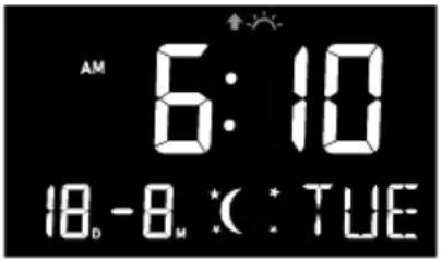 | ||
| [SET] Sunset normal Show the local sunset time | 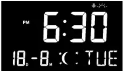 | ||
| [SET] Normal mode Current time and date | |||
VIEW YEAR
In normal mode you can view the year of today by press [V] or [ ].
MOON PHASE
The moon phase is determined by time and date of the console. The following table explains the moon phase icons of the Northern and Southern Hemispheres.
Please refer to the about how to setup for the Southern Hemisphere.
| Northern Hemisphere | Moon Phase | Southern Hemisphere |
 | New Moon |  |
 | Waxing Crescent |  |
 | First quarter |  |
 | Waxing Gibbous |  |
 | Full Moon |  |
 | Waning Gibbous |  |
 | Third quarter |  |
 | Waning Crescent |  |
WIRELESS SENSOR SIGNAL RECEIVING
- The console display signal strength for the wireless sensor(s), as per table below:
| No signal Weak | signal Good signal |
- If the signal has discontinued and does not recover within 15 minutes, the signal icon will disappear. The temperature and humidity will display "Er" for the corresponding channel.
- If the signal does not recover within 48 hours, the "Er" display will become permanent. You need to replace the batteries and then press [SENSOR / WI-FI] to pair up the sensor again.
TREND INDICATOR
The trend indicator shows the temperature humidity and barometric pressure trends of changes in the forthcoming few minutes.



Rising Steady Falling
VIEW OUTDOOR TEMPERATURE AND HUMIDITY
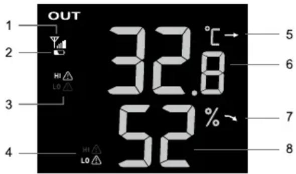
This console can display outdoor temperature and humidity reading with trend as below screen.
Overview
- 7-in-1 sensor signal indicator to show the signal receiving strength
- 7-in-1 sensor array low battery indicator
- Outdoor temperature high / low alert indicator
- Outdoor humidity high / low alert indicator
- Outdoor temperature trend
- Outdoor temperature
- Outdoor humidity trend
- Outdoor humidity
VIEW INDOOR, OPTIONAL THERMO-HYGRO AND LEAK CHANNELS
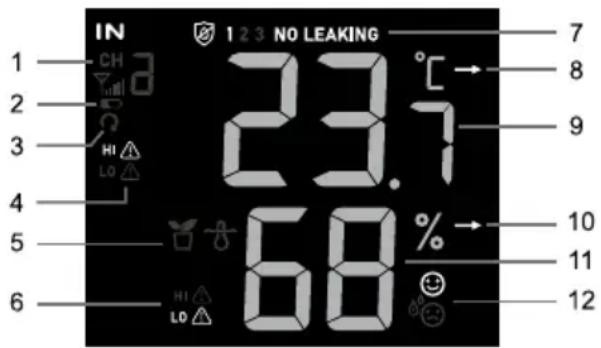
This console can display Indoor, CH1\~3 optional thermo-hygro sensor readings and CH1\~3 optional leak sensor status, In normal mode, you can press [CH] to switch between indoor and different wireless channels.
For auto-scroll function, just press and hold the [CH] for 3 seconds and the 🔒 icon will appear next to CH. The console will scroll the readings of all the sensors every 3 seconds.
Overview
- Indoor or optional thermo-hygro sensor icon with signal indicator to show the signal receiving strength
- Indoor or optional thermo-hygro sensor low battery indicator
- Channel auto loop icon
- Temperature high / low alert indicator
- Sensor type icon of optional sensor
- Humidity high / low alert indicator
- Water leak sensor status section
- Temperature trend
- Temperature reading
- Humidity trend
- Humidity reading
- Comfort index indicator
Water leak (optional leak sensor)
You can add up to 3 optional water Leak sensors.
The channel number(s) of the corresponding water leak sensor(s) added to the console will be shown with the NO LEAKING icon.
When water leaking is detected, the channel number of the sensor detecting the leaking will flash together the LEAKING icon.

123 NO LEAKING

123 NO LEAKING
NOTE:
When low battery is detected, the channel number of the sensor detecting the low battery condition will flash once every 4 seconds.
BAROMETRIC PRESSURE
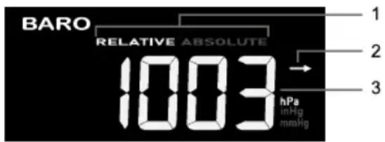
The atmospheric pressure is the pressure at any location of the earth caused by the weight of the column of air above it. One atmospheric pressure refers to the average pressure and gradually decreases as altitude increases. Meteorologists use barometers to measure atmospheric pressure. Because absolute atmospheric pressure decreases with altitude, meteorologist correct the pressure relative to sea-level conditions. Hence, your ABS pressure may read 1000 hPa at altitude of 300m, but the REL pressure is 1013 hPa.
To obtain accurate REL pressure for your area, consult your local official observatory or check weather website on internet for real time barometer conditions, and then adjust the relative pressure in calibration mode.
- Relative or Absolute indicator
- Barometric pressure trend
- Barometric pressure reading
Absolute or relative barometric pressure mode
In normal mode, press [BARO] to switch between ABSOLUTE and RELATIVE barometric pressure.
View feels like, dew point and optional sensor's reading
This console can also display feels like, dew point, and air pollutant readings of connected optional air quality sensor(s) data as below sequence by pressing the [MODE].
Overview
- Signal strength indicator for different optional air sensor(s)
- Battery level indicator for different optional air sensor(s)
- AQI indicator
- VOC level ( :good bad)
- Current readings high / low alert icons
- Current reading indicators
- Auto loop icon
- Pollutant level indicator
- Feels like, Dew point or other optional sensors (PM2.5, PM10, HCHO, VOC, CO₂ and CO) reading
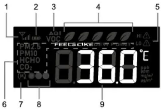
Press [MODE] to change the readings in following display sequence.
| Step Mode Display Screen | |||
| Feels like | 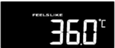 | ||
| [MODE] Dew point | 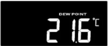 | ||
| [MODE] | PM2.5 concentration/AQI | 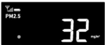 | 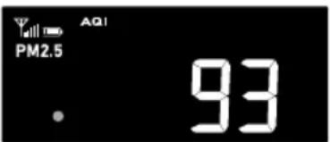 |
| Press [A] to toggle between concentration and AQI | |||
| [MODE] | PM10 concentration/AQI | 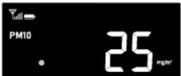 | 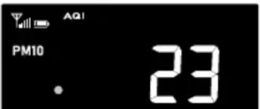 |
| Press [A] to toggle between concentration and AQI | |||
| [MODE] HCHO / VOC | 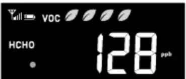 | ||
| [MODE] CO _2 concentration | 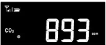 | ||
| [MODE] CO concentration | 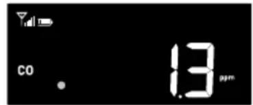 | ||
You can also press and hold [MODE] with 2 seconds to show different mode with 4 seconds interval. During "Auto loop" mode, the Ⓜ icon will shown on the display.
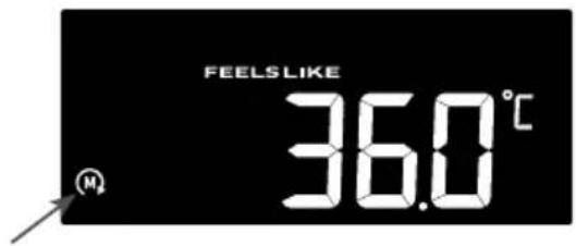
Feels like
Feels Like Temperature shows what the outdoor temperature will feel like. It's a collective mixture of Wind Chill factor (18°C or below) and the Heat Index (26°C or above). For temperatures in the region between 18.1°C to 25.9°C where both wind and humidity are less significant in affecting the temperature, the device will show the actual outdoor measured temperature as Feels Like Temperature.
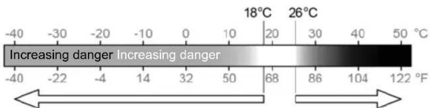
Wind Chill Heat index
Dew point
- The dew point is the temperature below which the water vapor in air at constant barometric pressure condenses into liquid water at the same rate at which it evaporates. The condensed water is called dew when it forms on a solid surface.
- The dew point temperature is determined by the temperature & humidity data from wireless 7-in-1 sensor.
Pollutant level indicator table for optional sensors
Red Yellow Green


Pollutant concentration level
| Type of pollutant of the optional sensors | High (Red) Normal (Yellow) Low (Green) | ||
| PM2.5 > 35 μg/m | ^3 | 13 ~ 35 μg/m ^3 | < 13 μg/m ^3 |
| PM10 > 154 μg/m | ^3 | 55 ~ 154 μg/m ^3 | < 55 μg/m ^3 |
| HCHO > 250ppb | 26 ~ 250ppb < 26ppb | ||
| Carbon Dioxide (CO _2 ) > | 1500ppm | 701 ~ 1500ppm | < 701ppm |
| Carbon Monoxide (CO) | >9.4ppm | 4.5 ~ 9.4ppm | < 4.5ppm |
WIND
Overview
- High wind speed alert indicator
- 10 minutes average / gust wind speed, Beaufort scale or wind direction (in degree).
- Wind speed reading.
- Real time wind direction indicator (16 points)
- Past wind directions indicator of last 5 minutes.
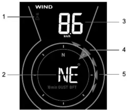
Wind direction, Gust and Beaufort Scale display
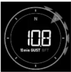
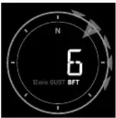
By default, wind direction is shown in 360 degrees. User can change the display by pressing [WIND] in following sequence
| Wind direction (360 degrees) | Wind direction (16 point compass) | Gust | Gust in past 10 minutes | Beaufort scale |
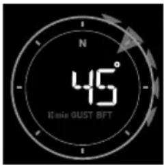 | 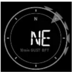 | 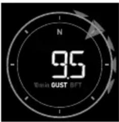 |  |  |
NOTE:
- Wind speed is defined as the average wind speed in the 12 second update period
- Gust is defined as the peak wind speed in the 12 second update period
Beaufort scale table
The Beaufort scale is an international scale of wind velocities ranging from 0 (calm) to 12 (Hurricane force).
| Beaufort Scale | Description Wind Speed Land Condition | ||
| 0 Calm | < 1 km/h | Calm. Smoke rises vertically. | |
| < 1 mph | |||
| < 1 knots | |||
| < 0.3 m/s | |||
| 1 Light air | 1.1 ~ 5km/h | Smoke drift indicates wind direction.Leaves and wind vanes are stationary. | |
| 1 ~ 3 mph | |||
| 1 ~ 3 knots | |||
| 0.3 ~ 1.5 m/s | |||
| 2 Light breeze | 6 ~ 11 km/h | Wind felt on exposed skin. Leaves rustle.Wind vanes begin to move. | |
| 4 ~ 7 mph | |||
| 4 ~ 6 knots | |||
| 1.6 ~ 3.3 m/s | |||
| Beaufort Scale | Description Wind | Speed Land Condition | |
| 3 Gentle breeze | 12 ~ 19 km/h | Leaves and small twigs constantly moving, light flags extended. | |
| 8 ~ 12 mph | |||
| 7 ~ 10 knots | |||
| 3.4 ~ 5.4 m/s | |||
| 4 | Moderate breeze | 20 ~ 28 km/h | Dust and loose paper raised. Small branches begin to move. |
| 13 ~ 17 mph | |||
| 11 ~ 16 knots | |||
| 5.5 ~ 7.9 m/s | |||
| 5 Fresh breeze | 29 ~ 38 km/h | Branches of a moderate size move. Small trees in leaf begin to sway. | |
| 18 ~ 24 mph | |||
| 17 ~ 21 knots | |||
| 8.0 ~ 10.7 m/s | |||
| 6 Strong breeze | 39 ~ 49 km/h | Large branches in motion. Whistling heard in overhead wires. Umbrella use becomes difficult. Empty plastic bins tip over. | |
| 25 ~ 30 mph | |||
| 22 ~ 27 knots | |||
| 10.8 ~ 13.8 m/s | |||
| 7 High wind | 50 ~ 61 km/h | Whole trees in motion. Effort needed to walk against the wind. | |
| 31 ~ 38 mph | |||
| 28 ~ 33 knots | |||
| 13.9 ~ 17.1 m/s | |||
| 8 Gale | 62 ~ 74 km/h | Some twigs broken from trees. Cars veer on road. Progress on foot is seriously impeded | |
| 39 ~ 46 mph | |||
| 34 ~ 40 knots | |||
| 17.2 ~ 20.7 m/s | |||
| 9 Strong gale | 75 ~ 88 km/h | Some branches break off trees, and some small trees blow over. Construction / temporary signs and barricades blow over. | |
| 47 ~ 54 mph | |||
| 41 ~ 47 knots | |||
| 20.8 ~ 24.4 m/s | |||
| 10 Storm | 89 ~ 102 km/h | Trees are broken off or uprooted, structural damage likely. | |
| 55 ~ 63 mph | |||
| 48 ~ 55 knots | |||
| 24.5 ~ 28.4 m/s | |||
| 11 Violent storm | 103 ~ 117 km/h | Widespread vegetation and structural damage likely. | |
| 64 ~ 73 mph | |||
| 56 ~ 63 knots | |||
| 28.5 ~ 32.6 m/s | |||
| 12 | Hurricane force | ≥ 118 km/h | Severe widespread damage to vegetation and structures. Debris and unsecured objects are hurled about. |
| ≥ 74 mph | |||
| ≥ 64 knots | |||
| ≥ 32.7m/s | |||
RAIN
Overview
- Period of rainfall and rain rate
- Rain alert indicator
- Reading of rainfall or rain rate
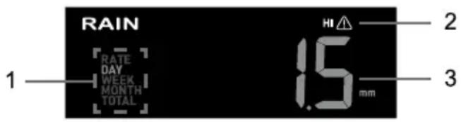
The rain display mode
Press [RAIN] to toggle between:
- RATE - current rainfall rate (base on 10 min rain data)
- DAY - the total rainfall from midnight (default)
- WEEK - the total rainfall of the current week
- MONTH - the total rainfall of the current calendar month
- TOTAL - the total rainfall since the last reset
Rain rate level definition
| Level 1 2 3 4 | ||||
| Description Light rain Moderate rain Heavy rain Violent rain | ||||
| Range (mm/h) 0.1~ | 2.5 2.51 ~ 10.0 10.1 | ~ 50.0 > 50.0 | ||
To reset the total rainfall record
In normal mode, press and hold [RAIN] for 6 seconds to reset all the rainfall record.
NOTE:
Erroneous readings may occur during the installation of the 7-in-1 sensor array. Once the installation is completed and functioning correctly, it's advisable to clear all the data and start afresh.
Light intensity, uv index and exposure level
- Recommended protection indicators
- UV index
- UV and light intensity alert indicator
- Light intensity
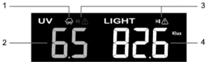
UV index vs exposure table
| Exposure level | Low Mo | Moderate High Very high | Extreme | |||||||||
| UV index | 1 | 2 | 3 | 4 | 5 | 6 | 7 | 8 | 9 | 10 | 11 | 12~16 |
| Sunburn time | N/A | 45 minutes | 30 minutes | 15 minutes | 10 minutes | |||||||
| Recommended protection | N/A | Moderate or high UV level!  Suggest to wear sunglasses,broad brim hat and longsleeved clothing. Suggest to wear sunglasses,broad brim hat and longsleeved clothing. | Very high or Extreme UV level!  Suggest to wear sunglasses,broad brim hat and long-sleeved clothing, If you have to stay outdoors, make sure to seek shade. Suggest to wear sunglasses,broad brim hat and long-sleeved clothing, If you have to stay outdoors, make sure to seek shade. | |||||||||
NOTE:
- The sunburn time is based on normal skin type, it is just a reference of UV strength. In general, the darker one's skin is, the longer (or more radiation) it takes to affect the skin.
- The light intensity function is for sunlight detection.
History graph
User may view the change of readings on graphs for different parameters over different time periods. All the graphs are based on rate of change with respect to their current values respectively, except the rainfall graph which is based on actual readings.
Graphs for different parameters over fixed time period
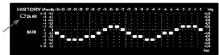
In normal mode, press [GRAPH] to view the history graph of different parameters over past 24 hours (default) in following display sequence:
| Step Mode Graph | ||
| Air pressure | 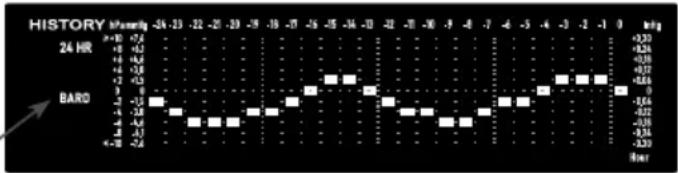 | |
| [GRAPH] Outdoor temperature | 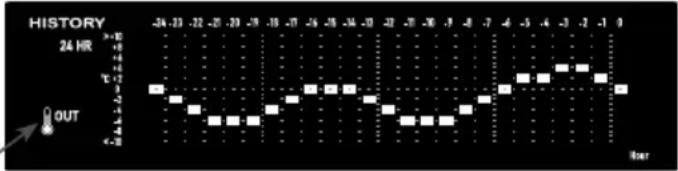 | |
| [GRAPH] Indoor temperature | 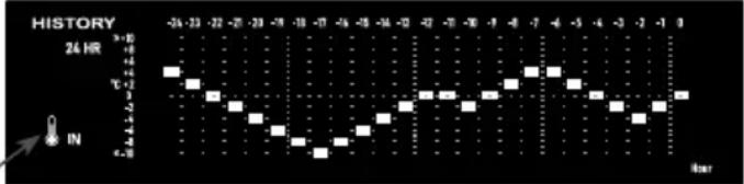 | |
| [GRAPH] Outdoor humidity | 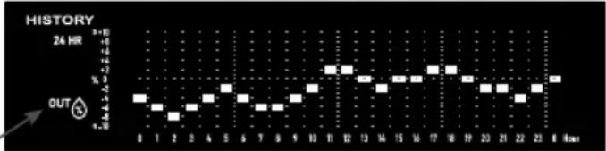 | |
| [GRAPH] Indoor humidity | 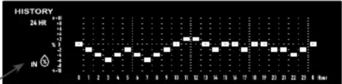 | |
| [GRAPH] Rainfall | 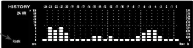 | |
| [GRAPH] Air pressure | ||
For auto-loop function press and hold [GRAPH] for 2 seconds as indicated by a white icon. Different weather graphs will be auto loop at 4 seconds intervals. Press [GRAPH] once to deactivate.
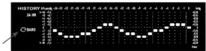
line
| Time (hours) | Value (pFmV) | | ------------ | ------------ | | 0 | -0.1 | | 10 | -0.1 | | 20 | -0.1 | | 30 | -0.1 | | 40 | -0.1 | | 50 | -0.1 | | 60 | -0.1 | | 70 | -0.1 | | 80 | -0.1 | | 90 | -0.1 | | 100 | -0.1 | | 110 | -0.1 | | 120 | -0.1 | | 130 | -0.1 | | 140 | -0.1 | | 150 | -0.1 | | 160 | -0.1 | | 170 | -0.1 | | 180 | -0.1 | | 190 | -0.1 | | 200 | -0.1 | | 210 | -0.1 | | 220 | -0.1 | | 230 | -0.1 | | 240 | -0.1 | | 250 | -0.1 | | 260 | -0.1 |In normal mode, press [HISTORY] to change the graph period in following sequence:
| Step Graph period Description | ||
| Past 24 hour | 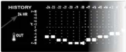 | |
| [HISTORY] Today | 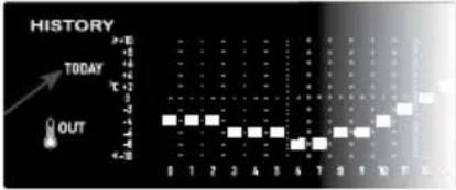 | |
| [HISTORY] -1 day (Yesterday) | 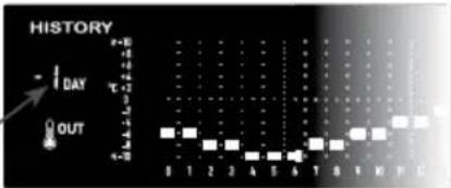 | |
| [HISTORY] -2 day (2 days ago) | 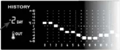 | |
| [HISTORY] -3 day (3 days ago) |  | |
| [HISTORY] Past 24 hour | ||
For rainfall graph, user may also view the past 24 days record (after -3 days).
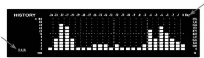
bar
HISTORY | Day | Rain (mm) | |---|---| | -24 | 1.0 | | -23 | 5.0 | | -22 | 10.0 | | -21 | 8.0 | | -20 | 6.0 | | -19 | 3.0 | | -18 | 2.0 | | -17 | 2.0 | | -16 | 3.0 | | -15 | 3.0 | | -14 | 3.0 | | -13 | 2.0 | | -12 | 3.0 | | -11 | 2.0 | | -10 | 2.0 | | -9 | 2.0 | | -8 | 2.0 | | -7 | 3.0 | | -6 | 10.0 | | -5 | 8.0 | | -4 | 10.0 | | -3 | 8.0 | | -2 | 5.0 | | -1 | 3.0 | | 0 | 2.0 | | 1 | 2.0 | | 2 | 2.0 | | 3 | 2.0 | | 4 | 2.0 | | 5 | 2.0 | | 6 | 2.0 | | 7 | 2.0 | | 8 | 2.0 | | 9 | 2.0 | | 10 | 2.0 | | 11 | 2.0 | | 12 | 2.0 | | 13 | 2.0 | | 14 | 2.0 | | 15 | 2.0 | | 16 | 2.0 | | 17 | 2.0 | | 18 | 2.0 | | 19 | 2.0 | | 20 | 2.0 | | 21 | 2.0 | | 22 | 2.0 | | 23 | 2.0 | | 24 | 2.0 | | 25 | 2.0 | | 26 | 2.0 | | 27 | 2.0 | | 28 | 2.0 | | 29 | 2.0 | | 30 | 2.0 | | 31 | 2.0 | | 32 | 2.0 | | 33 | 2.0 | | 34 | 2.0 | | 35 | 2.0 | | 36 | 2.0 | | 37 | 2.0 | | 38 | 2.0 | | 39 | 2.0 | | 40 | 2.0 | | 41 | 2.0 | | 42 | 2.0 | | 43 | 2.0 | | 44 | 2.0 | | 45 | 2.0 | | 46 | 2.0 | | 47 | 2.0 | | 48 | 2.0 | | 49 | 2.0 | | 50 | 2.0 | | 51 | 2.0 | | 52 | 2.0 | | 53 | 2.0 | | 54 | 2.0 | | 55 | 2.0 | | 56 | 2.0 | | 57 | 2.0 | | 58 | 2.0 | | 59 | 2.0 | | 60 | 2.0 | | 61 | 2.0 | | 62 | 2.0 | | 63 | 2.0 | | 64 | 2.0 | | 65 | 2.0 | | 66 | 2.0 | | 67 | 2.0 | | 68 | 2.0 | | 69 | 2.0 | | 70 | 2.0 | | 71 | 2.0 | | 72 | 2.0 | | 73 | 2.0 | | 74 | 2.0 | | 75 | 2.0 | | 76 | 2.0 | | 77 | 2.0 | | 78 | 2.0 | | 79 | 2.0 | | 80 | 2.0 | | Note: The data is already in millimeters, so no rainfall data is plotted for any given day or month in this view.For auto-loop function, press and hold [HISTORY] for 2 seconds, as indicated by a yellow icon. Different time periods of the chosen parameter will be auto loop at 4 seconds interval. Press [HISTORY] once to deactivate.
line
HISTORY □ 24 HR BARO +10 -7.3 -6.1 -4.1 +5 -4.3 -6.3 -4.9 +2 -4.5 -5 -4.1 -5 -4.3 -4 -4.6 -5 -4.1 +10 -7.6 -24 -22 -21 -20 -19 -18 -17 -16 -15 -14 -12 -12 -10 -9 -8 -9 -6 -8 -4 -7 -2 -4 -0 -3 +0 -2 -0 -1 +0 -1 +0 -1 +0 -1 +0 -1 +0 -1 +0 -1 +0 -1 +0 -1 +0 -1 +0 -1 +0 -1 +0 -1 +0 -1 +0 -1 +0 -1 +0 -1 +0 -1 +0 -1 +0 -1 +0 -1 -24 -22 -21 -20 -19 -18 -17 -16 -15 -14 -12 -12 -10 -9 -8 -9 -6 -8 -4 -7 -2 -4 -0 -3 -2 -2 -0 -1 +0 -1 +0 -1 +0 -1 +0 -1 +0 -1 +0 -1 +0 -1 +0 -1 +0 -1 +0 -1 +0 -1 +0 -1 +0 -1 +0 -1 +0 -1 +0 -1 +0 -1 +0 -1 +34.88Weather forecast
The built-in barometer continually monitor atmosphere pressure. Based on the data collected, it can predict the weather conditions in the forthcoming 12\~24 hours within a 30\~50km (19\~31 miles) radius.

NOTE:
– The accuracy of a general pressure-based weather forecast is about 70% to 75%.
- The weather forecast is reflecting the weather situation for next 12\~24 hours, it may not necessarily reflect the current situation.
- The Snowy weather forecast is not based on the atmospheric pressure, but based on the temperature of outdoor. When the temperature is below -3^ (26°F), the Snowy weather icon will be displayed on the LCD.
MAX / MIN records
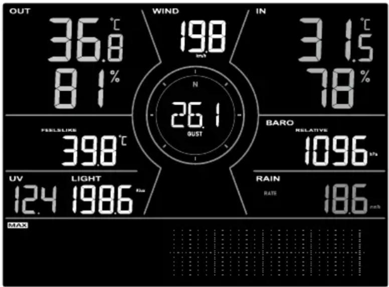
The console can show the different on screen reading's past 24 hours MAX / MIN records in memory mode.
other
| Metric | Value | | :--- | :--- | | OUT | 36.8 | | WIND | 198 | | IN | 3.15 | | N | 78 | | FEELSLIKE | 398 | | BARO RELATIVE | 1096 | | UV | 124 | | LIGHT | 198.6 | | RAIN RATE | 186 | MAX24 hours MAX record mode
To view MAX / MIN
In normal mode, press [MAX / MIN] to check records in following sequence: MAX 24 hours MIN 24 hours.
In MAX / MIN mode:
- Press [MODE] to switch between Feels like, Dew point and optional air pollutant's MAX / MIN records.
- Press [CH] to switch between indoor and CH1\~3 thermo-hygro MAX / MIN records.
To clear the MAX / MIN records
During the MAX / MIN mode, press and hold [MAX / MIN] for 2 seconds to reset all MAX / MIN records.
Weather alert setting
Weather Alert can alert you of certain weather conditions. Once the alert criterion is met, the alarm sound will activate and the LCD's alert icon will flash.
To view, set and activate alert
In normal mode, press [ALERT] to display the weather Hi / Lo alert readings and status in below sequence:
| Step Mode | Setting method | |
| [ALERT] | Outdoor temperature high alert | Hold 2 seconds to enter setting mode. Press [V] or [/] to adjust the value. Press [SET] to enable / disable alarm. |
| [ALERT] | Outdoor temperature low alert | Hold 2 seconds to enter setting mode. Press [V] or [/] to adjust the value. Press [SET] to enable / disable alarm. |
| [ALERT] | Outdoor humidity high alert | Hold 2 seconds to enter setting mode. Press [V] or [/] to adjust the value. Press [SET] to enable / disable alarm. |
| [ALERT] | Outdoor humidity low alert. | Hold 2 seconds to enter setting mode. Press [V] or [/] to adjust the value. Press [SET] to enable / disable alarm. |
| [ALERT] | Average wind speed high alert | Hold 2 seconds to enter setting mode. Press [V] or [/] to adjust the value. Press [SET] to enable / disable alarm. |
| [ALERT] | Indoor temperature high alert | Hold 2 seconds to enter setting mode. Press [V] or [/] to adjust the value. Press [SET] to enable / disable alarm. |
| [ALERT] | Indoor temperature low alert | Hold 2 seconds to enter setting mode. Press [V] or [/] to adjust the value. Press [SET] to enable / disable alarm. |
| [ALERT] | Indoor humidity high alert | Hold 2 seconds to enter setting mode. Press [V] or [/] to adjust the value. Press [SET] to enable / disable alarm. |
| [ALERT] | Indoor humidity low alert | Hold 2 seconds to enter setting mode. Press [V] or [/] to adjust the value. Press [SET] to enable / disable alarm. |
| [ALERT] | Feels like high alert | Hold 2 seconds to enter setting mode. Press [V] or [/] to adjust the value. Press [SET] to enable / disable alarm. |
| [ALERT] | Feels like low alert | Hold 2 seconds to enter setting mode. Press [V] or [/] to adjust the value. Press [SET] to enable / disable alarm. |
| [ALERT] | Dew point high alert | Hold 2 seconds to enter setting mode. Press [V] or [/] to adjust the value. Press [SET] to enable / disable alarm. |
| [ALERT] | Dew point low alert | Hold 2 seconds to enter setting mode. Press [V] or [/] to adjust the value. Press [SET] to enable / disable alarm. |
| [ALERT] | PM2.5 high alert | Hold 2 seconds to enter setting mode. Press [SET] to enable / disable alarm. |
| [ALERT] | PM10 high alert | Hold 2 seconds to enter setting mode. Press [SET] to enable / disable alarm. |
| [ALERT] HO | HO high alert | Hold 2 seconds to enter setting mode. Press [V] or [/] to adjust the value. Press [SET] to enable / disable alarm. |
| [ALERT] CO | _2 high alert | Hold 2 seconds to enter setting mode. Press [SET] to enable / disable alarm. |
| [ALERT] Pressure drop | Hold 2 seconds to enter setting mode. Press [V] or [/] to adjust the value. Press [SET] to enable / disable alarm. | |
| [ALERT] UV | high alert | Hold 2 seconds to enter setting mode. Press [V] or [/] to adjust the value. Press [SET] to enable / disable alarm. |
| [ALERT] Light intensity high alert | Hold 2 seconds to enter setting mode. Press [V] or [/] to adjust the value. Press [SET] to enable / disable alarm. | |
| [ALERT] Rain rate high alert | Hold 2 seconds to enter setting mode. Press [V] or [/] to adjust the value. Press [SET] to enable / disable alarm. | |
NOTE:
- Alert function is not applicable for Carbon Monoxide (CO).
- PM2.5, PM10, HCHO and CO_2 alert can be trigger by the high(red) pollutant level.
- Console will exit alert setting mode automatically, if no operation after 60 seconds.
Stop alert
You can stop the alert sound by following operation:
– Auto-stop after 2 minutes alert.
- By pressing [ALARM/SNOOZE] to stop the alert and the alert icon keep flashing.
CALIBRATION
The console is able to calibrate the weather and pollutant readings of the sensor(s):
- In normal mode, press [CAL] to enter the calibration mode.
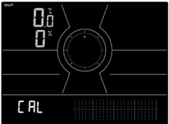
- Press [SET] to select different parameter.
- Press and hold [CAL] for 2 secs to enter adjust mode and the value will blinking.
- While the value is blinking, press [V] or [A] to adjust the value. To reset the current input value, you can press and hold the [SET] with 2 sec.
- Press [SET] to proceed with next parameter's calibration.
- To return normal mode, press [CAL] once.
OTHER FUNCTIONS
BACKLIGHT
The console backlight brightness can be adjust by using the [BACKLIGHT] slide switch to select the appropriate brightness:
- Slide to the [HI] position for the brighter backlight.
- Slide to the [LO] position for the dimmer backlight.
– Slide to the [AUTO] position for the auto adjust back light that according to environment light level
MAINTENANCE
Battery replacement
When low battery indicator “” appear on top of the sensors' reading, it indicates that the current sensor battery power is low respectively. Please replace with new batteries.
Changing batteries and manual pairing of sensor
Whenever you changed the batteries of the wireless sensor, re-synchronization must be done manually.
- Change all the batteries to new ones in the sensor.
- Press [SENSOR / WI-FI] on the console to enter sensor Synchronization mode.
- Console will re-register the sensor after its batteries are changed (about 1 minute).
Remove wireless sensor(s) connection
In order to remove the sensor(s) connection, please follow below steps:
- Remove sensor batteries.
- Press [SENSOR / WI-FI] once to clear the sensor history.
WIRELESS 7-IN-1 SENSOR ARRAY MAINTENANCE
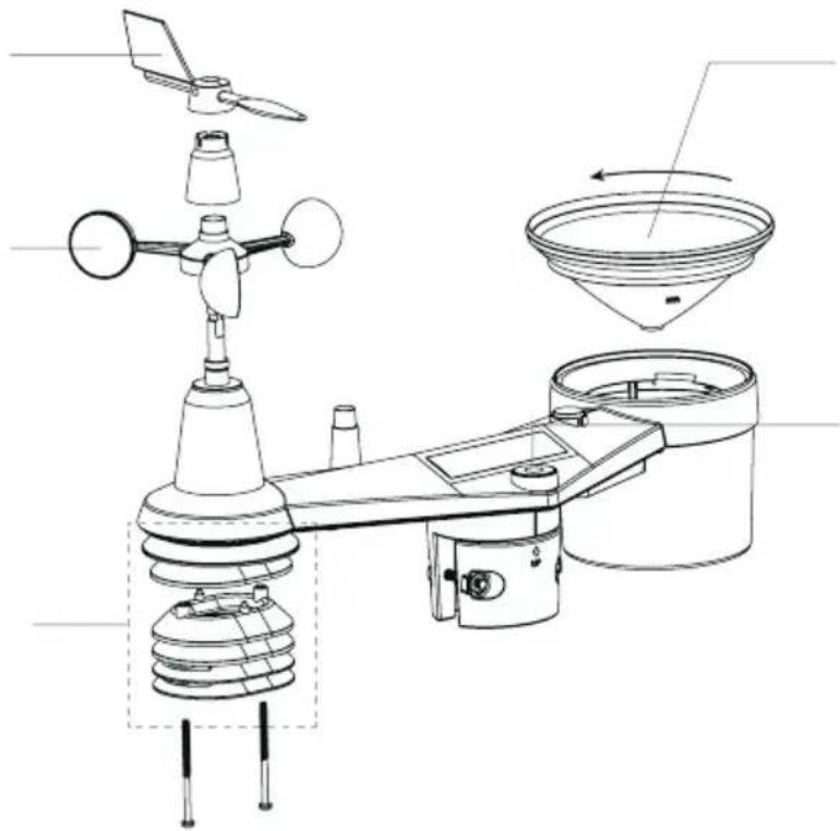
REPLACE THE WIND VANE
Unscrew and remove the wind vane for replacement
REPLACE THE WIND CUP
- Unscrew and remove the top cap
- Remove the wind cup for replacement
CLEANING HYGRO-THERMO SENSOR
- Remove the 2 screws at the bottom of the radiation shield.
- Gently pull out the shield.
- Carefully remove any dirt or insects on the sensor (do not let the sensors inside get wet).
- Clean the shield with water to remove any dirt or insects.
- Install all the parts back when they are clean and fully dried.
natural_image
Technical line drawing of an air conditioning or weather monitoring device with no visible text or symbolsCLEANING THE RAIN COLLECTOR
- Rotate the rain collector by turning it 30°anti-clockwise.
- Gently remove the rain collector
- Clean and remove any debris or insects.
- Install the collector when it is clean and fully dried.
CLEANING THE UV SENSOR AND CALIBRATION
- For precision UV measurement, gentle clean the UV sensor cover lens with damp micro-fiber cloth.
• Over time, the UV sensor will naturally degrade. The UV sensor can be calibrated with a utility grade UV meter, please refer to Calibration section in previous page for about the UV sensor calibration.
TROUBLESHOOT
| Problems Solution | |
| and (Signal lost for 15 minutes) and (Signal lost for 1 hour) | Make sure the console is placed away from other electronic Appliances that may interference with the wireless communication (TVs, computers, microwaves). |
| The Smart life app cannot pair up the console. | 1. Check for WI-FI symbol on the display, it should be alway on.2. Make sure you connect to 2.4G band but not 5G band of your WI-FI router. |
| Temperature or humidity not accurate 1 | Do not place your console or sensor close to the heat source2. If the sensor still not accurate adjust the value in calibration mode. |
| Console display no response or malfunction | You can follow the below step to fix:1. Remove the backup battery.2. Unplug the DC power jack.3. After 1 minute, plug the power jack again. |
SPECIFICATIONS
CONSOLE
| General specification | |
| Dimensions (W × H × D) 215 × 176.5 × | 27mm (8.5 × 6.9 × 1.1 in) |
| Weight 599 g (with Battery, without Adapter) | |
| Main power DC 5V, 1A adaptor | |
| Backup battery CR2032 3V button cell | |
| Operating temperature range -5°C ~ 50°C | |
| Operating Humidity range RH 10~90% | non-condensing |
| Support sensors (optional) | - Up to 3 Wireless Thermo-hygro sensors- Up to 3 Wireless water leak sensors- 1 wireless PM2.5 / PM10 sensor- 1 wireless HCHO / VOC sensor- 1 wireless CO2 sensor- 1 wireless CO sensor |
| RF frequency (Depend on country version) | 868Mhz |
| Time related function specification | |
| Time display HH: MM | |
| Hour format 12hr AM / PM or 24 hr | |
| Date display | MM / DD, DD / MM or Year |
| Time synchronize method Through Tuya to get the local time of the console location | |
| Weekday languages | EN / DE / FR / ES / IT / NL / RU |
| WI-FI communication specification | |
| Standard | 802.11 b/g/n |
| Operating frequency: | 2.4GHz |
| App specification | |
| Support app | - Tuya Smart- Smart Life |
| Supported platform of app | Android smart phoneiPhone |
| Barometer | |
| Barometer unit hPa, inHg and mmHg | |
| Accuracy | (700 ~ 1100hPa ± 5hPa) / (540 ~ 696hPa ± 8hPa) (20.67 ~ 32.48inHg ± 0.15inHg) / (15.95 ~ 20.55inHg ± 0.24inHg)(525 ~ 825mmHg ± 3.8mmHg) / (405 ~ 522mmHg ± 6mmHg)Typical at 25°C (77°F) |
| Resolution 1 hPa / inHg is 2 decimal place / mmHg is 1 decimal place | |
| Indoor temperature | |
| Temperature unit °C and °F | |
| Accuracy | ≤0°C ± 2°C (≤32°F ± 3.6°F)>0 °C ± 1°C (>32 °F ± 1.8°F) |
| Resolution °C / °F (1 decimal place) | |
| Indoor humidity | |
| Humidity unit % | |
| Accuracy | 1 ~ 9% RH ± 8% RH @ 25°C (77°F)10 ~ 90% RH ± 5% RH @ 25°C (77°F)91 ~ 99% RH ± 8% RH @ 25°C (77°F) |
| Resolution 1% | |
| Outdoor temperature | |
| Temperature unit °C and °F | |
| Weather index mode Feels like and Dew point | |
| Feels like display range -65 ~ 50°C | |
| Dew point display range -20 ~ 80°C | |
| Accuracy | 5.1 ~ 60°C ± 0.4°C (41.2 ~ 140°F ± 0.7°F)-19.9 ~ 5°C ± 1°C (-3.8 ~ 41°F ± 1.8°F)-40 ~ -20°C ± 1.5°C (-40 ~ -4°F ± 2.7°F) |
| Resolution °C / °F (1 decimal place) | |
| Outdoor humidity | |
| Humidity unit % | |
| Accuracy | 1 ~ 20% RH ± 6.5% RH @ 25°C (77°F)21 ~ 80% RH ± 3.5% RH @ 25°C (77°F)81 ~ 99% RH ± 6.5% RH @ 25°C (77°F) |
| Resolution 1% | |
| Wind speed & direction | |
| Wind speed unit mph, m/s, km/h and knots | |
| Wind speed display range 0 ~ 112mph, | 50m/s, 180km/h, 97knots |
| Resolution mph, m/s, km/h and knots (1 decimal place) | |
| Speed accuracy < 5m/s: +/- 0.8m/s; > 5m/s: +/- 10% (whichever is greater) | |
| Display mode Gust / Average | |
| Wind direction display mode 16 directions or 360 degree | |
| Rain | |
| Unit for rainfall mm and in | |
| Unit for rain rate mm/h and in/h | |
| Accuracy ± 7% or 1 tip | |
| Range | 0 ~ 19999mm (0 ~ 787.3 in) |
| Resolution 0.254mm (3 decimal place in mm) | |
| Rain display mode Rate / Hourly / Daily | / Weekly / Monthly / Total rainfall |
| UV index | |
| Display range 0 ~ 16 | |
| Resolution 1 decimal place | |
| Light intensity | |
| Light intensity unit Klux, Kfc and W/m | ^2 |
| Display range 0 ~ 200Klux | |
| Resolution Klux, Kfc and W/m | ^2 (2 decimal place) |
WIRELESS 7-IN-1 SENSOR
| Dimensions (W × H × D) | 390 × 217 × 165 mm (15.4 × 8.5 × 6.5in) (not include pole and stand) |
| Weight 831 g (with pole & stand, without batteries) | |
| Main power | 3 × AA size 1.5V batteries(Non-rechargeable Lithium batteries recommended) |
| Weather data | Temperature, Humidity, Wind speed, Wind direction, Rainfall, UV and light intensity |
| RF frequency 868MHz | |
| RF transmission range 150m (492 feet) | straight distance |
| Transmission interval 12 seconds | |
| Operating temperature range -40 ~ 60°C (-40 ~ 140°F) | |
| Operating humidity range RH 1% to 99 % non-condensing | |
WIRELESS THERMO-HYGROMETER SENSOR
| Dimensions (W × H × D) 58 × 125 × 19 | mm (2.3 × 4.9 × 0.7in) |
| Weight 144g (with Batteries) | |
| Main power | 2 × AA size 1.5V batteries(Alkaline batteries recommended) |
| Weather data Temperature and Humidity | |
| RF transmission range 150m (492 feet) | straight distance |
| RF frequency (depend on country version) | 868MHz |
| Transmission interval 60 seconds | |
| Operating temperature range | -40 ~ 60°C (-40 ~ 140°F) Non-rechargeable Lithium batteries required |
| Operating humidity range RH 1% to 99 | % non-condensing |
| CH (wireless sensor) Temperature | |
| Temperature unit °C and °F | |
| Accuracy -40 ~ 60°C ± 0.4°C (-40 ~ 140°F ± 0.7°F) | |
| Resolution °C / °F (1 decimal place) | |
| CH (wireless sensor) Humidity | |
| Humidity unit | % |
| Accuracy | 1 ~ 90% RH ± 2.5% RH @ 25°C (77°F)90 ~ 99% RH ± 3.5% RH @ 25°C (77°F) |
| Resolution 1% | |
| Adapter technical specifications: | |
| Manufacturer's name or trade mark, commercial registration number and address: | Dongguan Shijie Hua Xu Electronics Factory, No.200, Technology East Road, Shijie Town, Dongguan City, Guangdong P.R. China |
| Model identifier: HX075-0501000-AG-001 | |
| Input voltage: AC100 - 240V | |
| Input AC frequency: 50/60Hz | |
| Output voltage: DC5.0V | |
| Output current: 1.0A | |
| Output power: 5.0W | |
| Average active efficiency: ≥73.62% | |
| Efficiency at low load (10 %): 64.93% | |
| No-load power consumption: ≤0.01W | |
INSTRUCTIONS AND INFORMATION REGARDING THE DISPOSAL OF USED PACKAGING MATERIALS
Dispose of packaging material at a public waste disposal site.
DISPOSAL OF USED ELECTRICAL AND ELECTRONIC APPLIANCES
The meaning of the symbol on the product, its accessory or packaging indicates that this product shall not be treated as household waste. Please, dispose of this product at your applicable collection point for the recycling of electrical & electronic equipment waste. Alternatively in some states of the European Union or other European states you may return your products to your local retailer when buying an equivalent new product. The correct disposal of this product will help save valuable natural resources and help in preventing the potential negative impact on the environment and human health, which could be caused as a result of improper liquidation of waste. Please ask your local authorities or the nearest waste collection centre for further details. The improper disposal of this type of waste may fall subject to national regulations for fines.
For business entities in the European Union
If you wish to dispose of an electrical or electronic device, request the necessary information from your seller or supplier.
Disposal in other countries outside the European Union
If you wish to dispose of this product, request the necessary information about the correct disposal method from local government departments or from your seller.

The product meets EU requirements.
Hereby, FAST ČR, a.s. declares that the radio equipment type SWS 16600 WiFi SH is in compliance with Directive 2014/53/EU.
The full text of the EU declaration of conformity is available at the following internet address: www.sencor.com
Changes to the text, design and technical specifications may occur without prior notice and we reserve the right to make these changes.
Address of the manufacturer: FAST ČR, a.s., U Sanitasu 1621, 251 01 Říčany, Czech Republic
SENCOR®
EN Warranty conditions
Warranty card is not a part of the device packaging.
This product is warranted for the period of 24 months from the date of purchase to the end-user. Warranty is limited to the following conditions. Warranty is referred only to the customer goods using for common domestic use. The claim for service can be applied either at dealer's shop where the product was bought, or at below mentioned authorized service shops. The end-user is obligated to set up a claim immediately when the defects appeared but only till the end of warranty period. The end user is obligated to cooperate to certify the claiming defects. Only completed and clean (according to hygienic standards) product will be accepted. In case of eligible warranty claim the warranty period will be prolonged by the period from the date of claim application till the date of taking over the product by end-user, or the date the end-user is obligated to take it over. To obtain the service under this warranty, end-user is obligated to certify his claim with duly completed following documents: receipt, certificate of warranty, certificate of installation.
This warranty is void especially if apply as follows:
■ Defects which were put on sale.
■ Wear-out or damage caused by common use.
The product was damaged by unprofessional or wrong installation, used in contrary to the applicable instruction manual, used in contrary to legal enactment and common process of use or used for another purpose which has been designed for.
■ The product was damaged by uncared-for or insufficient maintenance.
The product was damaged by dirt, accident of force majeure (natural disaster, fire, and flood).
■ Defects on functionality caused by low duality of signal, electromagnetic field interference etc.
■ The product was mechanically damaged (e.g. broken button, fall).
- Damage caused by use of unsuitable media, fillings, expendable supplies (batteries) or by unsuitable working conditions (e.g. high temperatures, high humidity, quakes).
■ Repair, modification or other failure action to the product by unauthorized person.
■ End-user did not prove enough his right to claim (time and place of purchase).
■ Data on presented documents differs from data on products.
- Cases when the claiming product cannot be identified according to the presented documents (e.g. the serial number or the warranty seal has been damaged).
Manufacturer:
FAST ČR, a.s., U Sanitasu 1621, Říčany 251 01, Czech Republic
Visit www.sencor.com for detailed information about authorized service centers.
The original version of the instructions is in the Czech language, other language versions are made by the appropriate translation.
OBSAH
natural_image
Technical line drawing of a propeller or fan assembly (no text or symbols)Krok 1 Krok 2
natural_image
Line drawing of a propeller or fan with blades and handle, no text or symbols presentnatural_image
Technical line drawing of a mechanical assembly with a valve and base plate (no text or symbols)POZNÁMKA:
natural_image
Technical diagram of a mechanical assembly with cylindrical components and internal spring-like components (no text or labels)natural_image
Pure mechanical component diagram without any text, numbers, or symbolsnatural_image
Technical line drawing of a mechanical assembly with arrows indicating motion or force direction (no text or symbols)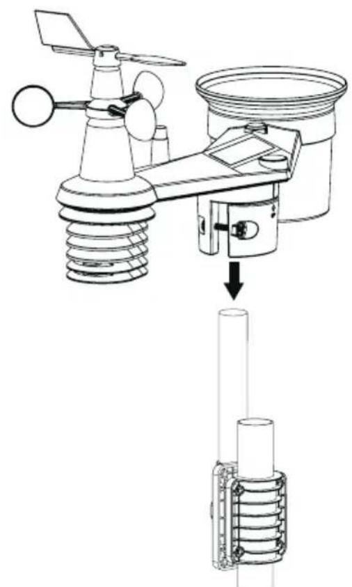
natural_image
Technical diagram of an air condition sensor assembly with a vertical tube inserted into a cylindrical component (no text or labels)POZNÁMKA:
POZNÁMKA:
natural_image
Diagram of a door with a scroll wheel and directional arrow indicating rotation (no text or symbols)SYNCHRONIZACE PŘÍDAVNÉHO SNÍMAČE (SNÍMAČŮ) (VOLITELNÉ)
ZOBRAZENÍ VNITŘNÍCH HODNOT, VOLITELNÝCH KANÁLŮ TEPLOTY, VLHKOSTI A ÚNIKU VODY
line
HISTORY I2Pamg - 24-23 -22 -21 -20 -19 -18 -17 -16 -15 -14 -13 -12 -11 -10 -9 -8 -7 -6 -5 -4 -3 -2 -1 | Time (ms) | Amplitude (pA) | | :--- | :--- | | 0 | +0.0 | | 1 | +0.1 | | 2 | +0.2 | | 3 | +0.3 | | 4 | +0.4 | | 5 | +0.5 | | 6 | +0.6 | | 7 | +0.7 | | 8 | +0.8 | | 9 | +0.9 | | 10 | +1.0 | | 11 | +1.1 | | 12 | +1.2 | | 13 | +1.3 | | 14 | +1.4 | | 15 | +1.5 | | 16 | +1.6 | | 17 | +1.7 | | 18 | +1.8 | | 19 | +1.9 | | 20 | +2.0 | | 21 | +2.1 | | 22 | +2.2 | | 23 | +2.3 | | 24 | +2.4 | | 25 | +2.5 | | 26 | +2.6 | | 27 | +2.7 | | 28 | +2.8 | | 29 | +2.9 | | 30 | +3.0 | | 31 | +3.1 | | 32 | +3.2 | | 33 | +3.3 | | 34 | +3.4 | | 35 | +3.5 | | 36 | +3.6 | | 37 | +3.7 | | 38 | +3.8 | | 39 | +3.9 | | 40 | +4.0 | | 41 | +4.1 | | 42 | +4.2 | | 43 | +4.3 | | 44 | +4.4 | | 45 | +4.5 | | 46 | +4.6 | | 47 | +4.7 | | 48 | +4.8 | | 49 | +4.9 | | 50 | +5.0 | | 51 | +5.1 | | 52 | +5.2 | | 53 | +5.3 | | 54 | +5.4 | | 55 | +5.5 | | 56 | +5.6 | | 57 | +5.7 | | 58 | +5.8 | | 59 | +5.9 | | 60 | +6.0 | | 61 | +6.1 | | 62 | +6.2 | | 63 | +6.3 | | 64 | +6.4 | | 65 | +6.5 | | 66 | +6.6 | | 67 | +6.7 | | 68 | +6.8 | | 69 | +6.9 | | 70 | +7.0 | | 71 | +7.1 | | 72 | +7.2 | | 73 | +7.3 | | 74 | +7.4 | | 75 | +7.5 | | 76 | +7.6 | | 77 | +7.7 | | 78 | +7.8 | | 79 | +7.9 | | 80 | +8.0 | | 81 | +8.1 | | 82 | +8.2 | | 83 | +8.3 | | 84 | +8.4 | | 85 | +8.5 | | 86 | +8.6 | | 87 | +8.7 | | 88 | +8.8 | | 89 | +8.9 | | 90 | +9.0 | | 91 | +9.1 | | 92 | +9.2 | | 93 | +9.3 | | 94 | +9.4 | | 95 | +9.5 | | 96 | +9.6 | | 97 | +9.7 | | 98 | +9.8 | | 99 | +9.9 | | 100 | +10.0| +0.0 -0.1 -0.2 -0.3 -0.4 -0.5 -0.6 -0.7 -0.8 -0.9 -1.0 -1.1 -1.2 -1.3 -1.4 -1.5 -1.6 -1.7 -1.8 -1.9 -2.0 -2.1 -2.2 -2.3 -2.4 -2.5 -2.6 -2.7 -2.8 -2.9 -3.0 -3.1 -3.2 -3.3 -3.4 -3.5 -3.6 -3.7 -3.8 -3.9 -4.0 -4.1 -4.2 -4.3 -4.4 -4.5 -4.6 -4.7 -4.8 -4.9 -5.0 -5.1 -5.2 -5.3 -5.4 -5.5 -5.6 -5.7 -5.8 -5.9 -6.0 -6.1 -6.2 -6.3 -6.4 -6.5 -6.6 -6.7 -6.8 -6.9 -7.0 -7.1 -7.2 -7.3 -7.4 -7.5 -7.6 -7.7 -7.8 -7.9 -8.0 -8.1 -8.2 -8.3 -8.4 -8.5 -8.6 -8.7 -8.8 -8.9 -9.0 -9.1 -9.2 -9.3 -9.4 -9.5 -9.6 -9.7 -9.8 -9.9 -10.0| +0. +0. +0. +0. +0. +0. +0. +0. +0. +0. +0. +0. +0. +0. +0. +0. +0. +0. +0. +0. +0. +0. +0. +0. +0. +0. +0. +0. +0. +0. +0. +0. +0. +0. + 0. +0. +0. +0. +0. +0. +0. +0. +0. +0. +0. +0. +0. +0. +0. +0. +0. +0. +0. +0. +0. +0. +0. +0. +0. +0. +0. +0. +0. +0. +0. +0. +0. +natural_image
Technical line drawing of a weather monitoring instrument with labeled components (no text or symbols present)ČIŠTĚNÍ SBĚRAČE DEŠTĚ
natural_image
Technical line drawing of a propeller or fan assembly (no text or symbols)Krok 1 Krok 2
natural_image
Line drawing of a propeller with two blades and a handle, no text or symbols presentnatural_image
Technical line drawing of a mechanical assembly with a base platform and mounting bracket (no text or symbols)POZNÁMKA:
natural_image
Technical line drawing of a mechanical assembly with cylindrical components and coiled spring (no text or symbols)natural_image
Technical line drawing of a mechanical assembly with arrows indicating motion or force direction (no text or symbols)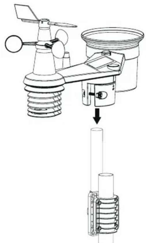
natural_image
Technical diagram of an air condition sensor assembly with a vertical tube inserted into a cylindrical component (no text or labels)POZNÁMKA:
- LED indikátor stavu prenosu
- Držiak na montáž na stenu
- Posuvný prepínač [CHANNEL] na priradenie snímača kanálu 1, 2, 3, 4, 5, 6
alebo 7
- Tlačidlo [RESET] (Resetovanie)
- Priestor na batérie
POZNÁMKA:
natural_image
Diagram of a door with a scroll wheel and directional arrow indicating rotation (no text or symbols)SYNCHRONIZÁCIA PRÍDAVNÉHO SNÍMAČA (SNÍMAČOV) (VOLITEL'NÉ)
ZOBRAZENIE VNÚTORNÝCH HODNÔT, VOLITELŇNÝCH KANÁLOV TEPLOTY, VLHKOSTI A ÚNIKU VODY
Režim zobrazenia dažd'a
Stlačte tlačidlo [RAIN] na prepnutie medzi:
line
HISTORY 24 HR | Label | Value | |---|---| | 10 | +7.1 | | 11 | +6.7 | | 12 | +6.5 | | 13 | +6.3 | | 14 | +6.1 | | 15 | +5.9 | | 16 | +5.7 | | 17 | +5.5 | | 18 | +5.3 | | 19 | +5.1 | | 20 | +4.9 | | 21 | +4.7 | | 22 | +4.5 | | 23 | +4.3 | | 24 | +4.1 | | 25 | +3.9 | | 26 | +3.7 | | 27 | +3.5 | | 28 | +3.3 | | 29 | +3.1 | | 30 | +2.9 | | 31 | +2.7 | | 32 | +2.5 | | 33 | +2.3 | | 34 | +2.1 | | 35 | +1.9 | | 36 | +1.7 | | 37 | +1.5 | | 38 | +1.3 | | 39 | +1.1 | | 40 | +0.9 | | 41 | +0.7 | | 42 | +0.5 | | 43 | +0.3 | | 44 | +0.1 | | 45 | 0.1 | | 46 | 0.3 | | 47 | 0.5 | | 48 | 0.7 | | 49 | 0.9 | | 50 | 1.1 | | 51 | 1.3 | | 52 | 1.5 | | 53 | 1.7 | | 54 | 1.9 | | 55 | 2.1 | | 56 | 2.3 | | 57 | 2.5 | | 58 | 2.7 | | 59 | 2.9 | | 60 | 3.1 | | 61 | 3.3 | | 62 | 3.5 | | 63 | 3.7 | | 64 | 3.9 | | 65 | 4.1 | | 66 | 4.3 | | 67 | 4.5 | | 68 | 4.7 | | 69 | 4.9 | | 70 | 5.1 | | 71 | 5.3 | | 72 | 5.5 | | 73 | 5.7 | | 74 | 5.9 | | 75 | 6.1 | | 76 | 6.3 | | 77 | 6.5 | | 78 | 6.7 | | 79 | 6.9 | | 80 | 7.1 | | -10 | -2.6 | The chart displays a single data series labeled 'BARO' with values ranging from approximately -2.6 to -2.0 dBm, plotted against time in hours on the x-axis and signal amplitude on the y-axis.bar
HISTORY | Day | Rain (mm) | |---|---| | -24 | 1.0 | | -23 | 5.0 | | -22 | 8.0 | | -21 | 6.0 | | -20 | 4.0 | | -19 | 2.0 | | -18 | 1.0 | | -17 | 1.0 | | -16 | 1.0 | | -15 | 1.0 | | -14 | 1.0 | | -13 | 1.0 | | -12 | 1.0 | | -11 | 1.0 | | -10 | 1.0 | | -9 | 1.0 | | -8 | 1.0 | | -7 | 1.0 | | -6 | 1.0 | | -5 | 3.0 | | -4 | 5.0 | | -3 | 7.0 | | -2 | 4.0 | | -1 | 2.0 | | 0 | 1.0 | | 1 | 1.0 | | 2 | 1.0 | | 3 | 1.0 | | 4 | 1.0 | | 5 | 1.0 | | 6 | 1.0 | | 7 | 1.0 | | 8 | 1.0 | | 9 | 1.0 | | 10 | 1.0 | | 11 | 1.0 | | 12 | 1.0 | | 13 | 1.0 | | 14 | 1.0 | | 15 | 1.0 | | 16 | 1.0 | | 17 | 1.0 | | 18 | 1.0 | | 19 | 1.0 | | 20 | 1.0 | | 21 | 1.0 | | 22 | 1.0 | | 23 | 1.0 | | 24 | 1.0 | | 25 | 1.0 | | 26 | 1.0 | | 27 | 1.0 | | 28 | 1.0 | | 29 | 1.0 | | 30 | 1.0 | | 31 | 1.0 | | 32 | 1.0 | | 33 | 1.0 | | 34 | 1.0 | | 35 | 1.0 | | 36 | 1.0 | | 37 | 1.0 | | 38 | 1.0 | | 39 | 1.0 | | 40 | 1.0 | | 41 | 1.0 | | 42 | 1.0 | | 43 | 1.0 | | 44 | 1.0 | | 45 | 1.0 | | 46 | 1.0 | | 47 | 1.0 | | 48 | 1.0 | | 49 | 1.0 | | 50 | 1.0 | | 51 | 1.0 | | 52 | 1.0 | | 53 | 1.0 | | 54 | 1.0 | | 55 | 1.0 | | 56 | 1.0 | | 57 | 1.0 | | 58 | 1.0 | | 59 | 1.0 | | 60 | 1.0 | | 61 | 1.0 | | 62 | 1.0 | | 63 | 1.0 | | 64 | 1.0 | | 65 | 1.0 | | 66 | 1.0 | | 67 | 1.0 | | 68 | 1.0 | | 69 | 1.0 | | 70 | 1.0 | | 71 | 1.0 | | 72 | 1.0 | | 73 | 1.0 | | 74 | 1.0 | | 75 | 1.0 | | 76 | 1.0 | | 77 | 1.0 | | 78 | 1.0 | | 79 | 1.0 | | 80 | 1.0 | | Note: The data for 'Rain' is not explicitly labeled in the image but is included in the text box as it is derived from the visual representation of the bars.natural_image
Technical line drawing of a weather monitoring instrument with labeled components (no text or symbols)ČISTENIE ZBERAČA DAŽDA
natural_image
Technical line drawing of a propeller or fan assembly (no text or symbols)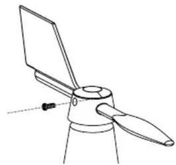
natural_image
Line drawing of a propeller with two blades and a handle, no text or symbols present- lépés 2. lépés
natural_image
Technical line drawing of a mechanical assembly with a base platform and a valve (no text or symbols)MEGJEGYZÉS:
natural_image
Technical diagram of a mechanical assembly with cylindrical components and internal spring-like components (no text or labels)natural_image
Pure mechanical component diagram without any text, numbers, or symbolsnatural_image
Technical line drawing of a mechanical assembly with arrows indicating motion or force direction (no text or symbols)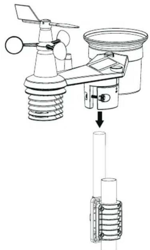
natural_image
Technical diagram of an air condition sensor assembly with a vertical tube inserted into a cylindrical component (no text or labels)MEGJEGYZÉS:
MEGJEGYZÉS:
natural_image
Diagram of a door with a scroll wheel and directional arrow indicating rotation (no text or symbols)KIEGÉSZÍTŐ ÉRZÉKELŐ (ÉRZÉKELŐK) SZINKRONIZÁLÁSA (OPCIONÁLIS)
BELSŐ ÉRTÉKEK, OPCIONÁLIS HÓMÉRSÉKLET-, PÁRATARTALOM- ÉS VÍZSZIVÁRGÁS CSATORNÁK MEGJELENÍTÉSE
line
HISTORY 24 HR | Label | Value | |---|---| | 10 | +7.1 | | 11 | +6.7 | | 12 | +6.5 | | 13 | +6.3 | | 14 | +6.1 | | 15 | +5.9 | | 16 | +5.7 | | 17 | +5.5 | | 18 | +5.3 | | 19 | +5.1 | | 20 | +4.9 | | 21 | +4.7 | | 22 | +4.5 | | 23 | +4.3 | | 24 | +4.1 | | 25 | +3.9 | | 26 | +3.7 | | 27 | +3.5 | | 28 | +3.3 | | 29 | +3.1 | | 30 | +2.9 | | 31 | +2.7 | | 32 | +2.5 | | 33 | +2.3 | | 34 | +2.1 | | 35 | +1.9 | | 36 | +1.7 | | 37 | +1.5 | | 38 | +1.3 | | 39 | +1.1 | | 40 | +0.9 | | 41 | +0.7 | | 42 | +0.5 | | 43 | +0.3 | | 44 | +0.1 | | 45 | 0.1 | | 46 | 0.3 | | 47 | 0.5 | | 48 | 0.7 | | 49 | 0.9 | | 50 | 1.1 | | 51 | 1.3 | | 52 | 1.5 | | 53 | 1.7 | | 54 | 1.9 | | 55 | 2.1 | | 56 | 2.3 | | 57 | 2.5 | | 58 | 2.7 | | 59 | 2.9 | | 60 | 3.1 | | 61 | 3.3 | | 62 | 3.5 | | 63 | 3.7 | | 64 | 3.9 | | 65 | 4.1 | | 66 | 4.3 | | 67 | 4.5 | | 68 | 4.7 | | 69 | 4.9 | | 70 | 5.1 | | 71 | 5.3 | | 72 | 5.5 | | 73 | 5.7 | | 74 | 5.9 | | 75 | 6.1 | | 76 | 6.3 | | 77 | 6.5 | | 78 | 6.7 | | 79 | 6.9 | | 80 | 7.1 | | -10 | -2.6 | The chart displays a single data series labeled 'BARO' with values ranging from -2.6 to -2.0 dBm, plotted against time (in hours). The Y-axis is labeled 'dBm' and the X-axis is labeled 'Time'. The bars are colored in white, likely representing different signal intensities or conditions at each time point.natural_image
Technical line drawing of a weather monitoring instrument with labeled components (no text or symbols present)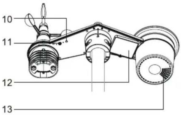
natural_image
Technical line drawing of a propeller or fan assembly (no text or symbols)Krok 1 Krok 2
natural_image
Line drawing of a propeller with two blades and a handle, no text or symbols presentnatural_image
Technical line drawing of a mechanical assembly with a base platform and a valve (no text or symbols)UWAGA:
natural_image
Technical diagram of a mechanical assembly with cylindrical components and coiled spring (no text or labels)natural_image
Diagram of a mechanical assembly with two components and directional arrows indicating motion (no text or symbols)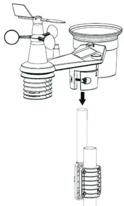
natural_image
Technical diagram of an air condition sensor assembly with a vertical tube inserted into a cylindrical component (no text or labels)UWAGA:
UWAGA:
natural_image
Diagram of a door with a scroll wheel and directional arrow indicating rotation (no text or symbols)SYNCHRONIZACJA DODATKOWEGO CZUJNIKA (CZUJNIKÓW) (OPCJONALNIE)
WYŚWIETLANIE WARTOŚCI WEWNĘTRZNYCH, OPCJONALNYCH KANAŁÓW TEMPERATURY, WILGOTNOŚCI I WYCIEKU WODY
line
HISTORY | Time | Value | |---|---| | -18 | +1.3 | | -17 | +1.4 | | -16 | +1.5 | | -15 | +1.6 | | -14 | +1.7 | | -13 | +1.8 | | -12 | +1.9 | | -11 | +2.0 | | -10 | +2.1 | | -9 | +2.2 | | -8 | +2.3 | | -7 | +2.4 | | -6 | +2.5 | | -5 | +2.6 | | -4 | +2.7 | | -3 | +2.8 | | -2 | +2.9 | | -1 | +3.0 | | 0 | +3.1 | | 1 | +3.2 | | 2 | +3.3 | | 3 | +3.4 | | 4 | +3.5 | | 5 | +3.6 | | 6 | +3.7 | | 7 | +3.8 | | 8 | +3.9 | | 9 | +4.0 | | 10 | +4.1 | | 11 | +4.2 | | 12 | +4.3 | | 13 | +4.4 | | 14 | +4.5 | | 15 | +4.6 | | 16 | +4.7 | | 17 | +4.8 | | 18 | +4.9 | | 19 | +5.0 | | 20 | +5.1 | | 21 | +5.2 | | 22 | +5.3 | | 23 | +5.4 | | 24 | +5.5 | | 25 | +5.6 | | 26 | +5.7 | | 27 | +5.8 | | 28 | +5.9 | | 29 | +6.0 | | 30 | +6.1 | | 31 | +6.2 | | 32 | +6.3 | | 33 | +6.4 | | 34 | +6.5 | | 35 | +6.6 | | 36 | +6.7 | | 37 | +6.8 | | 38 | +6.9 | | 39 | +7.0 | | 40 | +7.1 | | 41 | +7.2 | | 42 | +7.3 | | 43 | +7.4 | | 44 | +7.5 | | 45 | +7.6 | | 46 | +7.7 | | 47 | +7.8 | | 48 | +7.9 | | 49 | +8.0 | | 50 | +8.1 | | 51 | +8.2 | | 52 | +8.3 | | 53 | +8.4 | | 54 | +8.5 | | 55 | +8.6 | | 56 | +8.7 | | 57 | +8.8 | | 58 | +8.9 | | 59 | +9.0 | | 60 | +9.1 | | 61 | +9.2 | | 62 | +9.3 | | 63 | +9.4 | | 64 | +9.5 | | 65 | +9.6 | | 66 | +9.7 | | 67 | +9.8 | | 68 | +9.9 | | 69 | +10.0 | | 70 | +10.1 | | 71 | +10.2 | | 72 | +10.3 | | 73 | +10.4 | | 74 | +10.5 | | 75 | +10.6 | | 76 | +10.7 | | 77 | +10.8 | | 78 | +10.9 | | 79 | +11.0 | | 80 | +11.1 | | 81 | +11.2 | | 82 | +11.3 | | 83 | +11.4 | | 84 | +11.5 | | 85 | +11.6 | | 86 | +11.7 | | 87 | +11.8 | | 88 | +11.9 | | 89 | +12.0 | | 90 | +12.1 | | 91 | +12.2 | | 92 | +12.3 | | 93 | +12.4 | | 94 | +12.5 | | 95 | +12.6 | | 96 | +12.7 | | 97 | +12.8 | | 98 | +12.9 | | 99 | +13.0 | | 100 | +13.1 |natural_image
Technical line drawing of a weather monitoring instrument with labeled components (no text or symbols)CZYSZCZENIE ŁAPACZA
DESZCU
- ABOUT THIS USER'S MANUAL
- PRECAUTION & WARNING
- ! i
- INTRODUCTION
- QUICK START GUIDE
- PRE-INSTALLATION
- CHECKOUT
- SITE SELECTION
- GETTING STARTED
- INSTALL WIND VANE
- Install rain gauge funnel
- Install batteries
- NOTE:
- Sensor array installation
- Mounting kit set
- Plastic Mounting installation
- Direction alignment
- Pointing the wireless 7-in-1 sensor to south
- WIRELESS HYGRO-THERMO SENSOR
- Install wireless hygro-thermo sensor
- Placing the wireless thermo-hygro sensor
- SYNCHRONIZING ADDITIONAL SENSOR(S) (OPTIONAL)
- RECOMMENDATION FOR BEST WIRELESS COMMUNICATION
- POWER UP THE CONSOLE
- Install backup battery and power up
- Setup the console
- SYNCHRONIZING WIRELESS 7-IN-1 SENSOR AND HYGRO-THERMO SENSOR
- DATA CLEARING
- DISPLAY CONSOLE FUNCTION AND OPERATION
- SCREEN DISPLAY
- CONSOLE OVERVIEW
- CONSOLE FUNCTION AND OPERATION
- CONSOLE SETTINGS
- Setting mode
- SETTING ALARM TIME
- View and activate alarm time
- Suspend the time alarm
- VIEW YEAR
- MOON PHASE
- WIRELESS SENSOR SIGNAL RECEIVING
- TREND INDICATOR
- VIEW OUTDOOR TEMPERATURE AND HUMIDITY
- Overview
- VIEW INDOOR, OPTIONAL THERMO-HYGRO AND LEAK CHANNELS
- Water leak (optional leak sensor)
- BAROMETRIC PRESSURE
- Absolute or relative barometric pressure mode
- View feels like, dew point and optional sensor's reading
- Feels like
- Dew point
- Pollutant level indicator table for optional sensors
- WIND
- Wind direction, Gust and Beaufort Scale display
- Beaufort scale table
- RAIN
- The rain display mode
- Rain rate level definition
- To reset the total rainfall record
- Light intensity, uv index and exposure level
- UV index vs exposure table
- History graph
- Graphs for different parameters over fixed time period
- Weather forecast
- MAX / MIN records
- To view MAX / MIN
- To clear the MAX / MIN records
- Weather alert setting
- To view, set and activate alert
- Stop alert
- CALIBRATION
- OTHER FUNCTIONS
- BACKLIGHT
- MAINTENANCE
- Battery replacement
- Changing batteries and manual pairing of sensor
- Remove wireless sensor(s) connection
- WIRELESS 7-IN-1 SENSOR ARRAY MAINTENANCE
- REPLACE THE WIND VANE
- REPLACE THE WIND CUP
- CLEANING HYGRO-THERMO SENSOR
- CLEANING THE RAIN COLLECTOR
- CLEANING THE UV SENSOR AND CALIBRATION
- INSTRUCTIONS AND INFORMATION REGARDING THE DISPOSAL OF USED PACKAGING MATERIALS
- DISPOSAL OF USED ELECTRICAL AND ELECTRONIC APPLIANCES
- For business entities in the European Union
- Disposal in other countries outside the European Union
- SENCOR®
- EN Warranty conditions
- Warranty card is not a part of the device packaging.
- This warranty is void especially if apply as follows:
- Manufacturer:
- OBSAH
- POZNÁMKA:
- SYNCHRONIZACE PŘÍDAVNÉHO SNÍMAČE (SNÍMAČŮ) (VOLITELNÉ)
- ZOBRAZENÍ VNITŘNÍCH HODNOT, VOLITELNÝCH KANÁLŮ TEPLOTY, VLHKOSTI A ÚNIKU VODY
- ČIŠTĚNÍ SBĚRAČE DEŠTĚ
- SYNCHRONIZÁCIA PRÍDAVNÉHO SNÍMAČA (SNÍMAČOV) (VOLITEL'NÉ)
- ZOBRAZENIE VNÚTORNÝCH HODNÔT, VOLITELŇNÝCH KANÁLOV TEPLOTY, VLHKOSTI A ÚNIKU VODY
- Režim zobrazenia dažd'a
- ČISTENIE ZBERAČA DAŽDA
- MEGJEGYZÉS:
- KIEGÉSZÍTŐ ÉRZÉKELŐ (ÉRZÉKELŐK) SZINKRONIZÁLÁSA (OPCIONÁLIS)
- BELSŐ ÉRTÉKEK, OPCIONÁLIS HÓMÉRSÉKLET-, PÁRATARTALOM- ÉS VÍZSZIVÁRGÁS CSATORNÁK MEGJELENÍTÉSE
- UWAGA:
- SYNCHRONIZACJA DODATKOWEGO CZUJNIKA (CZUJNIKÓW) (OPCJONALNIE)
- WYŚWIETLANIE WARTOŚCI WEWNĘTRZNYCH, OPCJONALNYCH KANAŁÓW TEMPERATURY, WILGOTNOŚCI I WYCIEKU WODY
- CZYSZCZENIE ŁAPACZA
- DESZCU
Brand : SENCOR
Model : SWS 16600
Category : Weather Station