
KAM35 T - Air-conditioner GORENJE - Free user manual and instructions
Find the device manual for free KAM35 T GORENJE in PDF.

| Product Type | Portable Air Conditioner |
| Brand | Gorenje |
| Model | KAM35 T |
| Refrigerant Type | R290 (Flammable) |
| Refrigerant Charge | 0.936 kg |
| Cooling Capacity (Approx.) | 9000 BTU/h |
| Heating Capacity (Approx.) | 9000 BTU/h (Heat Pump Models) |
| Power Supply | 220-240 V ~ 50 Hz, 20 A Fuse |
| Power Input (Approx.) | 1000 W (Cooling/Heating) |
| Dimensions (W x D x H) | 350 x 450 x 700 mm (Estimated) |
| Weight (Net) | 25 kg (Estimated) |
| Exhaust Hose Length | 60 - 170 cm (Flexible) |
| Operating Modes | Cooling, Heating, Dry, Fan Only, Smart, Sleep |
| Fan Speeds | Auto, High, Medium, Low |
| Remote Control | Included (Battery: 2 x LR03 AAA) |
| Timer | 24-Hour On/Off Timer |
| Additional Functions | Silent Mode, Super Mode, IFEEL, Swing, Dimmer |
| Air Filter | Washable (Evaporator and Condenser) |
| Drainage | Manual Drain or Continuous Drain (Heat Pump Models) |
| Installation Options | Window (Vertical/Horizontal) or Through Wall |
| Minimum Clearance | 60 cm from Rear, 100 cm from Combustible Surfaces |
| Safety Features | R290 Precautions, Overheat Protection, Auto Restart |
| Certifications | CE, WEEE, RoHS |
Frequently Asked Questions - KAM35 T GORENJE
User questions about KAM35 T GORENJE
0 question about this device. Answer the ones you know or ask your own.
Ask a new question about this device
Download the instructions for your Air-conditioner in PDF format for free! Find your manual KAM35 T - GORENJE and take your electronic device back in hand. On this page are published all the documents necessary for the use of your device. KAM35 T by GORENJE.
USER MANUAL KAM35 T GORENJE
NAVODILA ZA UPORABO IN NAMESTITEV
USE AND INSTALLATION INSTRUCTIONS
UPUTE ZA UPORABU I POSTAVLJANJE
NÁVOD K POUŽITÍ A INSTALACI
INSTRUKCJA OBSŁUGI I MONTAŻU
NÁVOD NA POUŽITIE A INŠTALÁCIU
HASZNÁLATI ÉS ÜZEMBE HELYEZÉSI ÚTMUTATÓ
SI
EN
HR
CZ
PL
SK
HU
Thank you very much for purchasing this Air Conditioner. Please read this use and installation instructions carefully before installing and using this appliance and keep this manual for future reference.
NAVODILA ZA UPORABO IN NAMESTITEV
SI
natural_image
Pure mechanical cross-section diagram without any text, numbers, or symbolsnatural_image
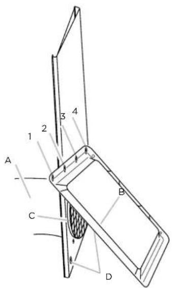
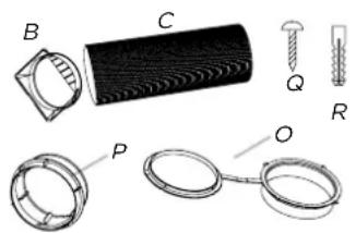
Technical illustration of mechanical components including a cylindrical component, ring, and fasteners (no text or symbols)A. Penasto tesnilo
B. Prilagoditvena spojnica
C. Fleksibilna odzračevalna cev
D. Okenski prilagoditveni priključek
E. Vijaka 1/2" (2)
F. Lesni vijaki (4)
G. Konzola za zaklepanje okna (2)
H. Dežni pokrov
1. Zunanja drsna letev
J. Notranja drsna letev
natural_image
Illustration of a hand holding a coiled tube wrapped in mesh material (no text or symbols)natural_image
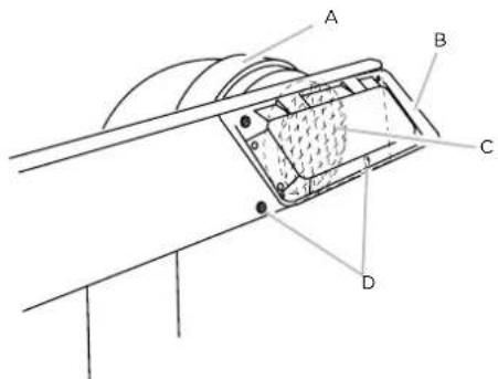
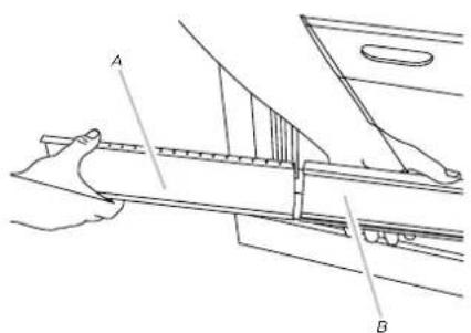
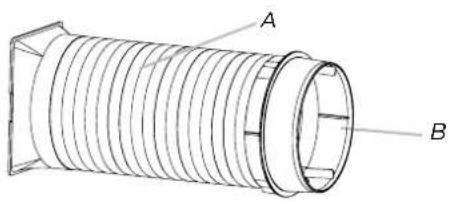
Technical line drawing of a coiled spring or hose assembly with labeled components A and B (no text or symbols beyond labels)A. Fleksibilna odzračevalna cev B. Okenski prilagoditveni priključek
A. Notranja drsna letev B
B. Zunanja drsna letev
natural_image
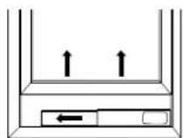
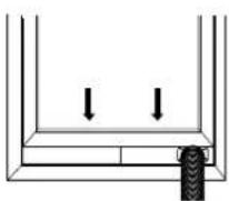
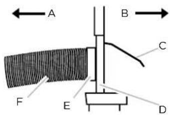
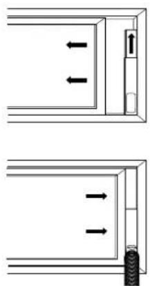
Simple line drawing of a door frame with two arrows indicating direction (no text or symbols)- Vstavite vijak 1/2" (priložena sta 2) v luknjo na notranji drsni letvi, ki je najbliže koncu zunanje drsne letve ...

natural_image
Illustration of a hand holding a coiled tube with a transparent frame, no text or symbols presentnatural_image
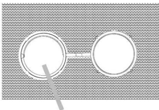
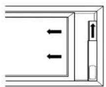
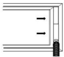
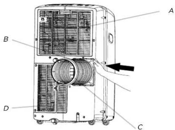
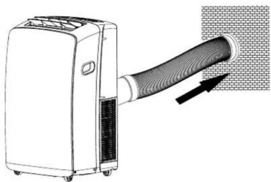
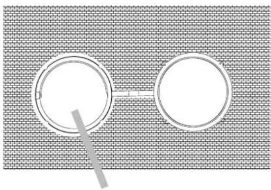
Illustration of a portable air conditioner unit with a coiled hose inserted, showing airflow direction (no text or symbols)Vstavite stenski prilagoditveni priključek za odzračevalno cev v stenski nastavek/rozeto.
- Odstranite stenski prilagoditveni priključek iz stenskega nastavka/rozete.
- Zaprite stenski nastavek s pokrovom.
natural_image
Two circular gauges placed on a brick-patterned surface, no text or symbols visiblePokrov
Uporaba lokalne klimatske naprave
-
Vstavite nove baterije. Prepričajte se, da sta pola (+) in (−) baterije ustrezno usmerjena.
-
Ponovno namestite pokrov prostora za baterije, tako da ga potisnete nazaj na njegovo mesto.
natural_image
Illustration of hands using a tool to adjust or install a component, enclosed in a circle with an arrow indicating rotation (no text or symbols present)OPOMBA:
- Uporabite dve bateriji LR03 AAA (1,5 V). Ne uporabljajte akumulatorskih baterij. Baterije zamenjajte z novimi baterijami istega tipa, ko postane prikazovalnik medel ali pa po šestih mesecih.
USE AND INSTALLATION INSTRUCTIONS
EN
Thank you very much for purchasing this Air Conditioner. Please read this use and installation instructions carefully before installing and using this appliance and keep this manual for future reference.
SAFETY PRECAUTIONS 2
IDENTIFICATION OF PARTS 10
AIR CONDITIONER SAFETY 11
INSTALLATION REQUIREMENTS 11
Tools and Parts 11
Location Requirements 11
Electrical Requirements 12
INSTALLATION INSTRUCTIONS 12
Unpack the Air Conditioner 12
Install Local Air Conditioner (on the window) 13
Complete Installation 15
Install Local Air Conditioner (through the wall) 16
Starting Your Local Air Conditioner 18
Using the Remote Control 19
Normal Sounds 23
Draining the Air Conditioner 24
Draining the Air Conditioner (Heating models) 24
Cleaning the Outside 24
Cleaning the Air Filter 24
Storing After Use 24
TROUBLESHOOTING 25
SAFETY INSTRUCTIONS
This appliance can be used by children aged from 8 years and above and persons with reduced physical, sensory or mental capabilities or lack of experience and knowledge if they have been given supervision or instruction concerning use of the appliance in a safe way and understand the hazards involved. Children shall not play with the
appliance. Cleaning and user maintenance shall not be made by children without supervision.
Children should be supervised to ensure that they do not play with the appliance. If the supply cord is damaged, it must be replaced by the manufacturer, its service agent or similarly qualified persons in order to avoid a hazard. The appliance shall be installed in accordance with national wiring regulations. The range of external static pressures is -0.2Pa to 0.2Pa. Keep the unit 5m or more apart from combustible surfaces. Do not operate your air conditioner in a wet room such as a bathroom or laundry room.
SAFEGUARDING THE ENVIRONMENT
This appliance is made of recyclable or re-usable material. Scrapping must be carried out in compliance with local waste disposal regulations. Before scrapping it, make sure to cut off the mains cord so that the appliance cannot be re-used. For more detailed information on handling and recycling this product, contact your local authorities who deal with the separate collection of rubbish or the shop where you bought the appliance.
SCRAPPING OF APPLIANCE
This appliance is marked according to the European Directive 2012/19/EU, Waste Electrical and Electronic Equipment (WEEE).
This marking indicates that this product should not be disposed with other household wastes throughout the EU. To prevent possible harm to the environment or human health from uncontrolled waste disposal, recycle it responsibly to promote the sustainable reuse of material resources. To return your used device, please use the return and collection systems or contact the retailer where the product was purchased. They can take this product for environmental safe recycling.
natural_image
Simple line drawing of a trash bin with diagonal lines crossing through it (no text or symbols)Precautions for using R290 refrigerant
However, pay attention to the following points:
The basic installation work procedures are the same as the conventional refrigerant (R22 or R410A).

CAUTION
Precautions for using R290 refrigerant
However, pay attention to the following points:
The basic installation work procedures are the same as the conventional refrigerant (R22 or R410A).
1. Transport of equipment containing flammable refrigerants
Compliance with the transport regulations
2. Marking of equipment using signs
Compliance with local regulations
3. Disposal of equipment using flammable refrigerants
Compliance with national regulations
4. Storage of equipment/appliances
The storage of equipment should be in accordance with the manufacturer's instructions.
5. Storage of packed (unsold) equipment
- Storage package protection should be constructed such that mechanical damage to the equipment inside the package will not cause a leak of the refrigerant charge.
- The maximum number of pieces of equipment permitted to be stored together will be determined by local regulations.
6. Information on servicing
6-1 Checks to the area
Prior to beginning work on systems containing flammable refrigerants, safety checks are necessary to ensure that the risk of ignition is minimised. For repair to the refrigerating system, the following precautions shall be complied with prior to conducting work on the system.
6-2 Work procedure
Work shall be undertaken under a controlled procedure so as to minimise the risk of flammable gas or vapour being present while the work is being performed.
6-3 General work area
- All maintenance staff and others working in the local area shall be instructed on the nature of work being carried out. Work in confined spaces shall be avoided.
- The area around the workspace shall be sectioned off. Ensure that the conditions within the area have been made safe by control of flammable material.
6-4 Checking for presence of refrigerant
- The area shall be checked with an appropriate refrigerant detector prior to and during work, to ensure the technician is aware of potentially flammable atmospheres.
- Ensure that the leak detection equipment being used is suitable for use with flammable refrigerants, i.e. non-sparking, adequately sealed or intrinsically safe.

CAUTION
6-5 Presence of fire extinguisher
- If any hot work is to be conducted on the refrigeration equipment or any associated parts, appropriate fire extinguishing equipment shall be available to hand.
- Have a dry powder or CO_2 fire extinguisher adjacent to the charging area.
6-6 No ignition sources
- No person carrying out work in relation to a refrigeration system which involves exposing any pipe work that contains or has contained flammable refrigerant shall use any sources of ignition in such a manner that it may lead to the risk of fire or explosion.
- All possible ignition sources, including cigarette smoking, should be kept sufficiently far away from the site of installation, repairing, removing and disposal, during which flammable refrigerant can possibly be released to the surrounding space.
- Prior to work taking place, the area around the equipment is to be surveyed to make sure that there are no flammable hazards or ignition risks. "No Smoking" signs shall be displayed.
6-7 Ventilated area
- Ensure that the area is in the open or that it is adequately ventilated before breaking into the system or conducting any hot work.
- A degree of ventilation shall continue during the period that the work is carried out.
- The ventilation should safely disperse any released refrigerant and preferably expel it externally into the atmosphere.
6-8 Checks to the refrigeration equipment
- Where electrical components are being changed, they shall be fit for the purpose and to the correct specification.
- At all times the manufacturer's maintenance and service guidelines shall be followed. If in doubt consult the manufacturer's technical department for assistance.
- The following checks shall be applied to installations using flammable refrigerants:
- The charge size is in accordance with the room size within which the refrigerant containing parts are installed;
- The ventilation machinery and outlets are operating adequately and are not obstructed;
- If an indirect refrigerating circuit is being used, the secondary circuit shall be checked for the presence of refrigerant;
- Marking to the equipment continues to be visible and legible. Markings and signs that are illegible shall be corrected;
- Refrigeration pipe or components are installed in a position where they are unlikely to be exposed to any substance which may corrode refrigerant containing components, unless the components are constructed of materials which are inherently resistant to being corroded or are suitably protected against being so corroded.

CAUTION
6-9 Checks to electrical devices
- Repair and maintenance to electrical components shall include initial safety checks and component inspection procedures.
- If a fault exists that could compromise safety, then no electrical supply shall be connected to the circuit until it is satisfactorily dealt with.
- If the fault cannot be corrected immediately but it is necessary to continue operation, an adequate temporary solution shall be used.
- This shall be reported to the owner of the equipment so all parties are advised.
- Initial safety checks shall include:
- That capacitors are discharged: this shall be done in a safe manner to avoid possibility of sparking;
- That there no live electrical components and wiring are exposed while charging, recovering or purging the system;
– That there is continuity of earth bonding.
7. Repairs to sealed components
- During repairs to sealed components, all electrical supplies shall be disconnected from the equipment being worked upon prior to any removal of sealed covers, etc.
- If it is absolutely necessary to have an electrical supply to equipment during servicing, then a permanently operating form of leak detection shall be located at the most critical point to warn of a potentially hazardous situation.
- Particular attention shall be paid to the following to ensure that by working on electrical components, the casing is not altered in such a way that the level of protection is affected.
- This shall include damage to cables, excessive number of connections, terminals not made to original specification, damage to seals, incorrect fitting of glands, etc.
- Ensure that apparatus is mounted securely.
- Ensure that seals or sealing materials have not degraded such that they no longer serve the purpose of preventing the ingress of flammable atmospheres.
- Replacement parts shall be in accordance with the manufacturer's specifications.
NOTE:
The use of silicon sealant may inhibit the effectiveness of some types of leak detection equipment. Intrinsically safe components do not have to be isolated prior to working on them.
8. Repair to intrinsically safe components
- Do not apply any permanent inductive or capacitance loads to the circuit without ensuring that this will not exceed the permissible voltage and current permitted for the equipment in use.
- Intrinsically safe components are the only types that can be worked on while live in the presence of a flammable atmosphere. The test apparatus shall be at the correct rating.
- Replace components only with parts specified by the manufacturer.
- Other parts may result in the ignition of refrigerant in the atmosphere from a leak.

CAUTION
9. Cabling
- Check that cabling will not be subject to wear, corrosion, excessive pressure, vibration, sharp edges or any other adverse environmental effects.
- The check shall also take into account the effects of aging or continual vibration from sources such as compressors or fans.
10. Detection of flammable refrigerants
- Under no circumstances shall potential sources of ignition be used in the searching for or detection of refrigerant leaks.
- A halide torch (or any other detector using a naked flame) shall not be used.
11. Leak detection methods
- The following leak detection methods are deemed acceptable for systems containing flammable refrigerants:
- Electronic leak detectors shall be used to detect flammable refrigerants, but the
- sensitivity may not be adequate, or may need re-calibration. (Detection equipment shall be calibrated in a refrigerant-free area.)
- Ensure that the detector is not a potential source of ignition and is suitable for the refrigerant used.
- Leak detection equipment shall be set at a percentage of the LFL of the refrigerant and shall be calibrated to the refrigerant employed and the appropriate percentage of gas (25 % maximum) is confirmed.
- Leak detection fluids are suitable for use with most refrigerants but the use of detergents containing chlorine shall be avoided as the chlorine may react with the refrigerant and corrode the copper pipework.
- If a leak is suspected, all naked flames shall be removed/ extinguished.
- If a leakage of refrigerant is found which requires brazing, all of the refrigerant shall be recovered from the system, or isolated (by means of shut off valves) in a part of the system remote from the leak.
- Oxygen free nitrogen (OFN) shall then be purged through the system both before and during the brazing process.
12. Removal and evacuation
- When breaking into the refrigerant circuit to make repairs – or for any other purpose – conventional procedures shall be used.
- However, it is important that best practice is followed since flammability is a consideration.
-
The following procedure shall be adhered to:
-
Remove refrigerant;
– Purge the circuit with inert gas;
-Evacuate;
– Purge again with inert gas; - Open the circuit by cutting or brazing.

CAUTION
- The refrigerant charge shall be recovered into the correct recovery cylinders.
- The system shall be "flushed" with OFN to render the unit safe.
- This process may need to be repeated several times.
- Compressed air or oxygen shall not be used for this task.
- Flushing shall be achieved by breaking the vacuum in the system with OFN and continuing to fill until the working pressure is achieved, then venting to atmosphere, and finally pulling down to a vacuum.
- This process shall be repeated until no refrigerant is within the system. When the final OFN charge is used, the system shall be vented down to atmospheric pressure to enable work to take place.
- This operation is absolutely vital if brazing operations on the pipe-work are to take place.
- Ensure that the outlet for the vacuum pump is not close to any ignition sources and there is ventilation available.
13. Charging procedures
- In addition to conventional charging procedures, the following requirements shall be followed.
- Ensure that contamination of different refrigerants does not occur when using charging equipment.
- Hoses or lines shall be as short as possible to minimise the amount of refrigerant contained in them.
– Cylinders shall be kept upright. - Ensure that the refrigeration system is earthed prior to charging the system with refrigerant.
- Label the system when charging is complete (if not already).
-
Extreme care shall be taken not to overfill the refrigeration system.
-
Prior to recharging the system it shall be pressure tested with OFN.
- The system shall be leak tested on completion of charging but prior to commissioning.
- A follow up leak test shall be carried out prior to leaving the site.
14. Decommissioning
- Before carrying out this procedure, it is essential that the technician is completely familiar with the equipment and all its detail.
- It is recommended good practice that all refrigerants are recovered safely.
- Prior to the task being carried out, an oil and refrigerant sample shall be taken in case analysis is required prior to re-use of reclaimed refrigerant. It is essential that electrical power is available before the task is commenced.
a) Become familiar with the equipment and its operation.
b) Isolate system electrically.

CAUTION
c) Before attempting the procedure ensure that:
- Mechanical handling equipment is available, if required, for handling refrigerant cylinders;
- All personal protective equipment is available and being used correctly;
– The recovery process is supervised at all times by a competent person; - Recovery equipment and cylinders conform to the appropriate standards.
d) Pump down refrigerant system, if possible.
e) If a vacuum is not possible, make a manifold so that refrigerant can be removed from various parts of the system.
f) Make sure that cylinder is situated on the scales before recovery takes place.
g) Start the recovery machine and operate in accordance with manufacturer's instructions.
h) Do not overfill cylinders. (No more than 80 % volume liquid charge).
I) Do not exceed the maximum working pressure of the cylinder, even temporarily.
j) When the cylinders have been filled correctly and the process completed, make sure that the cylinders and the equipment are removed from site promptly and all isolation valves on the equipment are closed off.
k) Recovered refrigerant shall not be charged into another refrigeration system unless it has been cleaned and checked.
15. Labelling
- Equipment shall be labelled stating that it has been de-commissioned and emptied of refrigerant.
- The label shall be dated and signed.
- Ensure that there are labels on the equipment stating the equipment contains flammable refrigerant.
16. Recovery
- When removing refrigerant from a system, either for servicing or decommissioning, it is recommended good practice that all refrigerants are removed safely.
- When transferring refrigerant into cylinders, ensure that only appropriate refrigerant recovery cylinders are employed.
- Ensure that the correct number of cylinders for holding the total system charge is available.
- All cylinders to be used are designated for the recovered refrigerant and labelled for that refrigerant (i.e. special cylinders for the recovery of refrigerant).
- Cylinders shall be complete with pressure relief valve and associated shutoff valves in good working order.
- Empty recovery cylinders are evacuated and, if possible, cooled before recovery occurs.
- The recovery equipment shall be in good working order with a set of instructions concerning the equipment that is at hand and shall be suitable for the recovery of flammable refrigerants.

CAUTION
- In addition, a set of calibrated weighing scales shall be available and in good working order.
- Hoses shall be complete with leak-free disconnect couplings and in good condition.
- Before using the recovery machine, check that it is in satisfactory working order, has been properly maintained and that any associated electrical components are sealed to prevent ignition in the event of a refrigerant release.
- Consult manufacturer if in doubt.
- The recovered refrigerant shall be returned to the refrigerant supplier in the correct recovery cylinder, and the relevant Waste Transfer Note arranged.
- Do not mix refrigerants in recovery units and especially not in cylinders.
- If compressors or compressor oils are to be removed, ensure that they have been evacuated to an acceptable level to make certain that flammable refrigerant does not remain within the lubricant.
- The evacuation process shall be carried out prior to returning the compressor to the suppliers.
- Only electric heating to the compressor body shall be employed to accelerate this process.
- When oil is drained from a system, it shall be carried out safely.

CAUTION
- When moving or relocating the air conditioner, consult experienced service technicians for disconnection and reinstallation of the unit.
- Do not place any other electrical products or household belongings under indoor unit or outdoor unit. Condensation dripping from the unit might get them wet, and may cause damage or malfunction of your property.
- Do not use means to accelerate the defrosting process or to clean, other than those recommended by the manufacturer.
- The appliance shall be stored in a room without continuously operating ignition sources (for example, open flames, an operating gas appliance or an operating electric heater).
- Do not pierce or burn.
- Be aware that refrigerants may not contain an odor.
- To keep ventilation openings clear of obstruction.
- The appliance shall be stored in a well-ventilated area where the room size corresponds to the room area as specified for operation.
- The appliance shall be stored in a room without continuously operating open flames (for example an operating gas appliance) and ignition sources (for example an operating electric heater).
- The appliance shall be stored so as to prevent mechanical damage from.

CAUTION
- Any person who is involved with working on or breaking into a refrigerant circuit should hold a current valid certificate from an industry-accredited assessment authority, which authorises their competence to handle refrigerants safely in accordance with an industry recognised assessment specification.
- Servicing shall only be performed as recommended by the equipment manufacturer.
- Maintenance and repair requiring the assistance of other skilled personnel shall be carried out under the supervision of the person competent in the use of flammable refrigerants.
- Do not use means to accelerate the defrosting process or to clean, other than those recommended by the manufacturer.
- Appliance shall be installed, operated and stored in a room with a floor area larger than:
- The pipe-work shall be complianced with national gas regulations.
- Spaces where refrigerant pipes shall be compliance with national gas regulations.
- The maximum refrigerant charge amount is 0.936 kg.
- Mechanical connectors used indoors shall comply with ISO 14903. When mechanical connectors are reused indoors, sealing parts shall be renewed. When flared joints are reused indoors, the flare part shall be re-fabricated.
- The installation of pipe-work shall be kept to a minimum.
- Mechanical connections shall be accessible for maintenance purposes.
$$ + \mathrm{AP} - 0 9 \mathrm{CR4GEJS00} (1 0. 3 \mathrm{m} ^ {2}), + \mathrm{AP} - 0 9 \mathrm{HR4GFJS01} (1 4. 4 \mathrm{m} ^ {2}), $$
$$ + \mathrm{AP} - 1 2 \mathrm{CR4GFJS00} (1 3. 6 \mathrm{m} ^ {2}), + \mathrm{AP} - 1 2 \mathrm{HR4GFJS00} (1 4. 4 \mathrm{m} ^ {2}). $$
Explanation of symbols displayed on the indoor unit or outdoor unit.
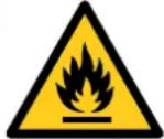 | WARNING | This symbol shows that this appliance uses a flammable refrigerant. If the refrigerant is leaked and exposed to an external |
 | CAUTION | This symbol shows that the operation manual should be read carefully. |
 | CAUTION | This symbol shows that a service personnel should be handling this equipment with reference to the installation manual. |
 | CAUTION | This symbol shows that information is available such as the operating manual or installation manual. |
Fuse parameter of the machine:
+ AP-09CR4GEJS00(T3.15A, 250V), + AP-09HR4GFJS01(T5A, 250V),
+ AP-12CR4GFJS00(T3.15A, 250V), + AP-12HR4GFJS00(T3.15A, 250V).
+ AP-09CR4GEJS00(T3.15A, 250V), + AP-09HR4GFJS01(T5A, 250V), + AP-12CR4GFJS00(T3.15A, 250V), + AP-12HR4GFJS00(T3.15A, 250V).
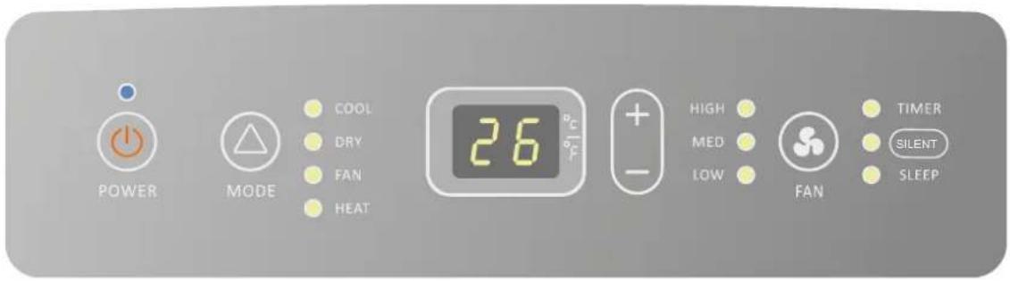
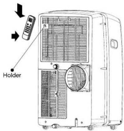
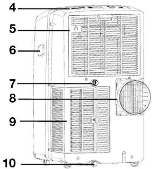
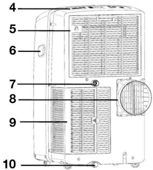
Front
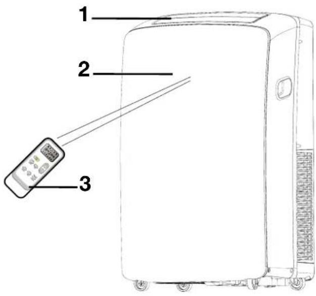
Back

1 Cool air outlet
2 Signal receptor
3 Remote control
4 Control panel
5 Evaporator air intake
6 Transport handle
7 Secondary drain port
8 Air outlet hose
9 Condenser air intake
10 Primary drain port
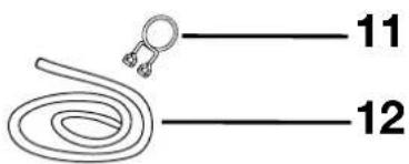
11 Drain hose clip (Heat pump models)
12 Drain hose (Heat pump models)

The figures in this manual are based on the externam view of a standard model. They may differ from that of the air conditioner you have selected.
You safety and the safety of others are very important.
We have provided many important safety messages in this manual and on your appliance. Always read and obey all safety messages.
alert symbol.
This symbol alerts you to potential hazards that can kill or hurt you and others.
All safety messages will follow the safety alert symbol and either the word "DANGER" or "WARNING".
an:
! DANGER
WARNING
You can be killed or seriously injured if you don't immediately follow instructions.
You can be killed or seriously injured if you don't follow instructions.
All safety messages will tell you what the potential hazard is, tell you how to reduce the chance of injury, and tell you what can happen if the instructions are not followed.
IMPORTANT SAFETY INSTRUCTIONS
WARNING: To reduce the risk of fire, electrical shock or injury when using your air conditioner, follow these basic precautions:
- Plug into a grounded 3 prong outlet.
- Do not remove ground prong.
-
Do not use an adapter.
-
Do not use an extension cord.
- Unplug air conditioner before servicing.
- Use two or more people to move and install air conditioner.
SAVE THESE INSTRUCTIONS
DISPOSING OF THE UNIT
- Before throwing the device, it is necessary to pull back the battery cells and get rid of them safety for recycling reasons.
- When you need to disposal of the unit consult our dealer. If pipes are removed incorrectly, refrigerant may blow out and please recycle or dispose of the packaging material for product in an environmentally responsible manner.
- Never store or ship the air conditioner upside down or sideways to avoid damage to the compressor.
- The appliance is not intended for use by young children or infirm persons without supervision. Young children should be come into contact with your skin, causing injury. Releasing refrigerant into the atmosphere also damages the environments, supervised to ensure that they do not play with the appliance.
Installation requirements
Tools and Parts
Gather the required tools and parts before starting installation.
Read and follow the instructions provided with any tools listed here.
Tools needed
- Phillips screwdriver
- Saw
-
Pencil
-
Scissors
- Cordless drill and ^1/_8 bit
Parts supplied
The campany provide only one plan to install portable air conditioner. See "Install Portable Air Conditioner"(P4-P8)
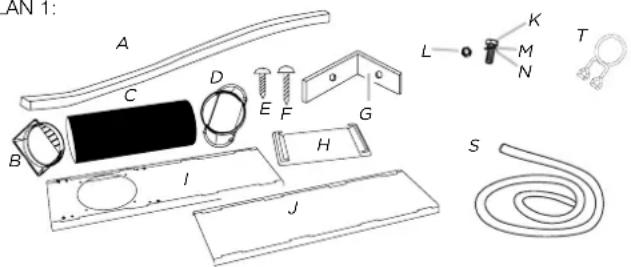
PLAN 1:
PLAN 2: (optional)

natural_image
Technical illustration of mechanical components including a cylindrical part, threaded fastener, and ring-like parts (no text or symbols)A. Foam seal
B. Dummy coupling
C. Flexible exhaust hose
D. Window exhaust adapter
E. 1/2"screws (2)
F. Wood screws(4)
G. Window-lock bracket(2)
H. Rain coverl.
1. Outer slider section
J. Inner slider section
K. Bolts (4)
L. Nuts (4)
M. Spring washers (4)
N. Plain washers (4)
O. Wall cover
P. Exhaust adapter
Q. Long Wood screws(3)
R. Plastics plug(3)
S. Drain hose(1)(Heating mode)
T. Drain hose clip(1)(Heating mode)
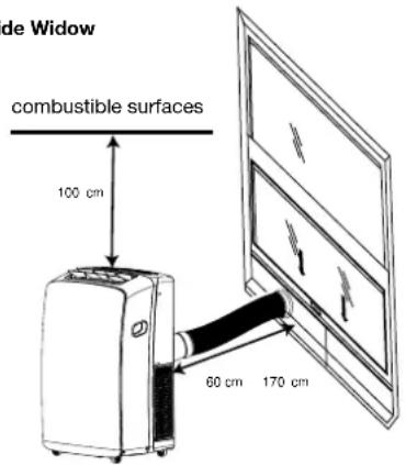
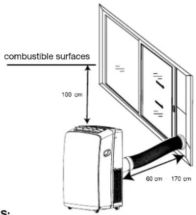
NOTES:
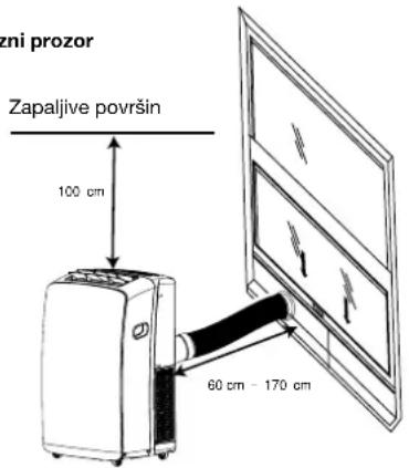
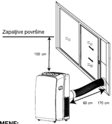
- The flexible exhaust hose allows placement of the air conditioner between 60 cm and 170 cm from window or door. For appliances with supplementary heaters, the minimum clearance from the appliances to combustible surfaces is 100 cm.
- Portable air conditioners are designed as supplemental cooling to local areas within a room.
Vertical Slide Widow
Electrical Requirements
Horizontal Slide Window
NOTES:
- To ensure proper ventilation, keep the required distance from the return air outlet to the wall or other obstacles at least 60 cm.
- Do not block the air outlet.
- Provide easy access to the grounded 3 prong outlet.

WARNING

Electrical Shock Hazard
Plug into a grounded 3 prong outlet.
Do not remove ground prong.
Do not use an adapter.
Do not use an extension cord.
Failure to follow these instructions can result in death, fire, or electrical shock.
- The portable air conditioner should be connected to a 220-240V, 50 HZ, 20-amp fuse grounded 3 prong outlet.
- The use of a time-delay fuse or time-delay circuit breaker is recommended.
- All wiring must comply with local and the national electrical codes and be installed by a qualified electrician. If you have any questions, contact a qualified electrician.
Installation instructions
Unpack the Air Conditioner

WARNING
Excessive Weight Hazard
Use two or more people to move and install air conditioner.
Failure to do so can result in back or other injury.
- Do not use sharp instruments, rubbing alcohol, flammable fluids, or abrasive cleaners to remove tape or glue. These products can damage the surface of your air conditioner.
- Handle the air conditioner gently.
Remove packaging materials
- Remove and dispose of/recycle packaging materials.
- Remove tape and glue residue from surfaces before turning on the air conditioner. Rub a small amount of liquid dish soap over the adhesive with your fingers. Wipe with warm water and dry.
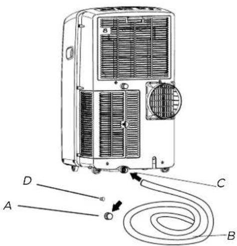
Install Exhaust Hose and Adapter
- Roll the air conditioner to selected location. see "Location Requirements."
- Attach the dummy coupling to the flexible exhaust hose. Turn anticlockwise until securely locked into place.
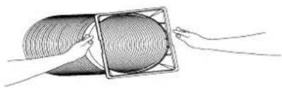
natural_image
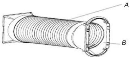
Illustration of two hands holding a coiled tube or pipe (no text or symbols visible)- Attach the window exhaust adapter to the flexible exhaust hose. Turn anticlockwise until securely locked into place.
natural_image
Technical line drawing of a coiled pipe or hose assembly with labeled components A and B (no text or symbols beyond labels)A. Flexible exhaust hose
B. Window exhaust adapter
- Insert the dummy coupling into the slot on the back of the air conditioner.
- Slide down to lock the hose into place.
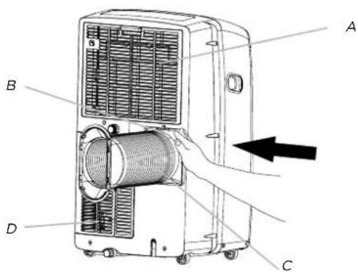
A. Evaporator air intake
B. Dummy coupling
C. Flexible exhaust hose
D. Condenser air intake
Window Installation
Your window slider kit has been designed to fit most standard vertical and horizontal window applications. Roll the air conditioner to selected location. see "Location Requirements."
- Insert the windows exhaust adapter into the slot on the window slider kit.
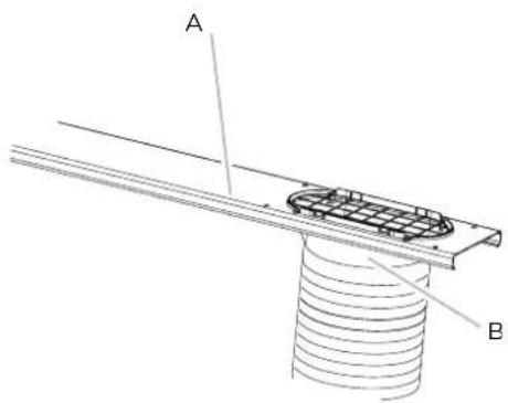
A. Window slider kit
B. Window exhaust adapter
Install Exhaust Hose and Adapter
- Using the 2 bolts, washer and nuts (provided), attach the rain cover to the window slider kit for either the vertical or horizontal installation.
NOTES:
- The holes in the window slider kit are positioned for attaching the rain cover for vertical or horizontal installation.
- Insert the other 2 bolts, washers and nuts (provided) into the unused holes in the window slider kit to keep moisture from leaking through the window slider kit.
Rain cover--Vertical Installation
A. Window exhaust adapter
B. Rain cover
C. Outlet grille
D. Bolts inserted into unused holes in Window slider kit
NOTES: Four holes in the rain cover for vertical installation. Insert the 2 bolts with "1" "3" or "2" "4".
A. Window exhaust adapter
B. Rain cover
C. Outlet grille
D. Bolts inserted into unused
holes in Window slider kit
-
Open the window.
-
Measure the window opening.
- If the window opening is too narrow for the window slider kit, remove the inner slider section from the window slider kit.
A. Inner slider section
B. Outer slider section
- Using a saw, cut the inner slider section to fit the window opening.
-
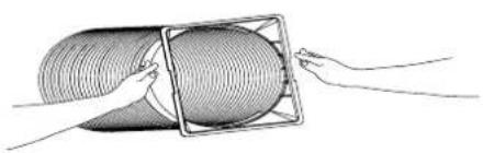
Slide the inner slider section into the outer slider section of the window slider kit.
-
Place the window slider kit into the window, extending it to fit the width of the window. Be sure the rain cover is on the outside of the window.
NOTE: For casement window installation, the window slider kit may be installed vertically with the window slider kit opening at the bottom.
natural_image
Simple line drawing of a door frame with two arrows indicating direction, no text or symbols present- Inset 1/2" screw (provide 2) into the hole in the inner slider section that is closest to the end of the outer slider section of
A. 1/2"screw (provide 2)
B. Inner slider section
C. Outer slider section
- Close the window onto the window slider kit to secure.
A. To portable air conditioner
B. Outdoors
C. Rain cover
D. Window slider kit
E. Window exhaust adapter
F. Flexible exhaust hose
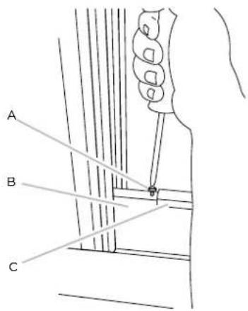
- Place the window-lock bracket on top of the lower window and against the upper window sash.
- Use 18 " drill bit to drill a starter hole through the hole in the bracket.
- Attach the window-lock bracket to the window sash with wood screw (provide 4) to secure the window in place.
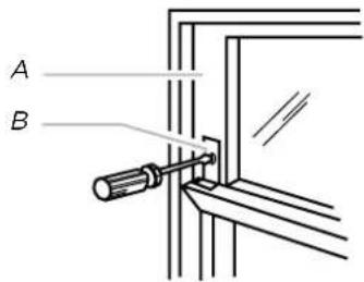
A. Upper window sash
B. Window-lock bracket
- Insert the foam seal behind the top of the lower window sash and against the glass of the upper window.
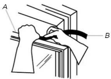
A. Top of lower window sash
B. Foam seal
WARNING

Electrical Shock Hazard
Plug into a grounded 3 prong outlet.
Do not remove ground prong.
Do not use an adapter.
Do not use an extension cord.
Failure to follow these instructions can result in death, fire, or electrical shock.
- Plug into a grounded 3 prong outlet.
Install Exhaust Hose and Adapter
- Roll the air conditioner to selected location. see "Location Requirements."
- Attach the dummy coupling to the flexible exhaust hose. Turn anticlockwise until securely locked into place.
natural_image
Diagram of a coiled tube being handled with a hand, showing internal structure and motion direction (no text or symbols)- Attach the window exhaust adapter to the flexible exhaust hose. Turn anticlockwise until securely locked into place.
natural_image
Technical line drawing of a coiled pipe with labeled components A and B (no text or symbols beyond labels)A. Flexible exhaust hose
B. Wall exhaust adapter
- Insert the dummy coupling into the slot on the back of the air conditioner.
- Slide down to lock the hose into place.
A. Evaporator air intake
B. Dummy coupling
C. Flexible exhaust hose
D. Condenser air intake
Drill a Hole for wall cover
- Decide the position of hole for wall cover according to the location of mounting plate.
- Drill a hole on the wall. The hole should a little bigger than wall cover.
- Install wall cover through the wall hole to keep the wall tidy and clean, fixed with four screws.
Insert the wall exhaust adapter to wall cover
- Insert the dummy coupling into the wall cover on the wall.
natural_image
Illustration of a portable air conditioner unit with a coiled hose inserted, showing airflow direction (no text or symbols)Insert the wall exhaust adapter to wall cover
- Remove wall exhaust adapter from the wall cover.
- Cover the wall cover.
natural_image
Two circular objects on a textured background, one with a diagonal line and the other empty, against a brick wall (no text or symbols)Cover
Operating your air conditioner local properly helps you to obtain the best possible results.
This section explains proper air conditioner operation.
IMPORTANT:
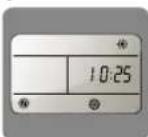
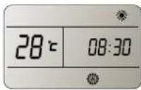
- The air conditioner display shows the setting temperature.
- Only in standby mode the display shows ambient temperature
-
When changing modes while the air conditioner is operation, the compressor will stop for 3 to 5 minutes before
-
If a button is pressed during this time, the compressor will not restart fo another 3 to 5 minutes.
- In Cooling or Dry mode, the compressor and condenser fan will stop when the room temperature reaches the set temperature.
NOTE:
In the event of a power failure, your air conditioner will operate at the previous settings when the power is restored.
Operating condition
| COOLING The best room temperature for the appliance work is 21 | °C~35°C |
| HEATING The best room temperature for the appliance work is 7 | °C~20°C |
| DRY The best room temperature for the appliance work is 19 | °C~35°C |
The temperature of some products is allowed beyond the range. In specific situation, please consult the merchant. If the air conditioner runs in COOLING or DRY mode withdoor or window opened for a long time when relative humidity is above 80%, dew may drip down from the outlet.
NOTE: The symbols may be different from these models, but the functions are similar.
- Select the mode. See "MODE".
- Select the fan speed. See "FAN".
- Set the temperature. See "TEMPERATURE".
- Press POWER button to start the air conditioner.

POWER
NOTE:
When the air conditioner is turned on, it will run according to the previous setting
Only if the unit is operated in UNLIKELY VERY HUMID air, water will be collected in the container inside the unit. If the water container is full, the air conditioner will stop. The screen will displays "E5" to inform you to empty the internal container.
Mode
Operating modes:
- Press and release MODE until you see the symbol flashes for the desired setting.

MODE
- Choose Cooling, Dry, Fan Only or Heating. Cooling-Cools the room. Press FAN to select High, Mid or Low. Press the Plus or Minus button to adjust the temperature.
COOL
Dry-Dries the room. The air conditioner automatically selects the temperature. The fan runs on Low speed only.
DRY
NOTE: Dry mode should not be used to cool the room. Fan Only-Only the fan runs. Press FAN to select High, Mid or Low.
FAN
Heating-heats the room. Press FAN to select high, Mid or Low. Press the PLUS or MINUS button to adjust the temperature.
NOTE: Heating is NOT available for cooling only air conditioner.
HEAT
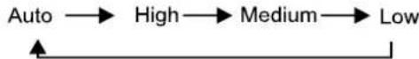
Fan Speed
- Press and release FAN to choose the desired fan speed.

FAN
- Choose High, Mid or Low. Auto-automatically controls the fan speed depending on the current room temperature and temperature control setting.
High-for maximum fan speed
HIGH
Mid-for normal fan speed
MED
Low-for minimum fan speed
LOW
Press the PLUS button to raise the temperature. Press the PLUS button once to increase the set temperature by 1°C.

Press the MINUS button to lower the temperature. Press the MINUS button once to decrease the set temperature by 1°C.

NOTE:
In the Cooling mode, the temperature can be set between 16°C and 30°C.
In Fan Only mode, the temperature cannot be set.
Press SILENT button to start the silent mode.

When the SILENT light on the control panel lights, the silent mode turn on.
Using the Remote Control
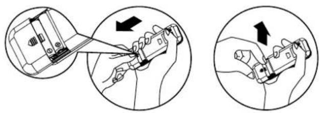
Insert the Batteries
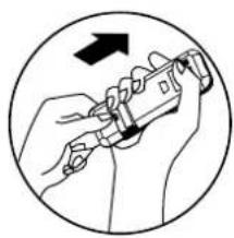
- Remove the battery cover to the arrow direction.

natural_image
Illustration showing two hand tools in a tool, one being inserted and the other holding a grip (no text or symbols present)-
Insert new batteries making sure that the (+) and (-) of battery are matched correctly.
-
Reattach the cover by sliding it back into position.
natural_image
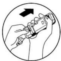
Illustration of hands using a tool to adjust or install a component, enclosed in a circle with an arrow indicating rotation (no text or symbols)NOTE:
- Use 2 LR03 AAA(1.5volt) batteries. Do not use rechargeable batteries. Replace batteries with new ones of the same type when the display becomes dim, or after 6 months.
- If you reload batteries over after removing the old ones, you will miss the presetting and the timer will go back to Zero.
Storage trip
The clip on the back of the unit can be used to store the remote control.
How to Use
To operate the room air conditioner, aim the remote controller to the signal receptor. The remote control will operate the air conditioner at a distance of up to 23' (7m) when pointing at signal receptor of the air conditioner.
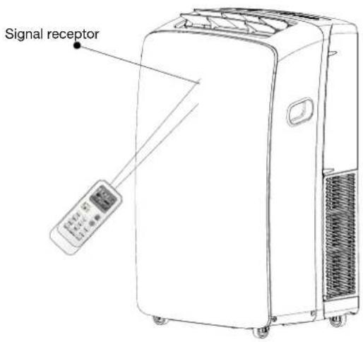
NOTE:
Remote control may differ in appearance.
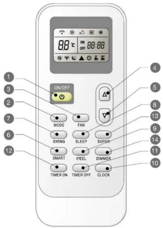
Press SILENT button to start the silent mode.
 |  | ON/OFF |  | [73BY] | SLEEP | |
 |  | MODE |  |  | IFEEL | |
| [X0B0] |  | FAN |  | [A0CA] | CLOCK | |
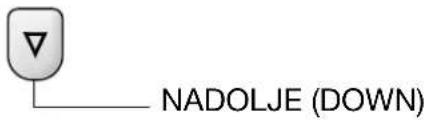
 |  | UP |  |  | Timer Off | |
 | [7YG3] | DOWN | [TXG3] | [2YST] | Timer On | |
 | [82ZH] | SMART |  |  | SUPER | |
| [SWDX] | [GXG2] | SWING | [XXXG] | [A6HW] | DIMMER |
Indication symbols
Indication symbols on LCD:
 |  | ng indicator Auto fan  3d 3d |
 |  | indicator High fan spe  |
 |  | only indicator Medium [XS2D] speed |
 |  | ng indicator Low fan speed |
▲Smart indicator Sign  | |
OFF  Display set timer Display set timer | |
| Display current time | |
Power On or Off
Press ON/OFF button to turn on or off the unit
NOTE:
- Changing modes during operating. Sometimes the unit does not response at once. Wait 3 minutes.
- Wait 3 minutes before restarting the appliance.
Mode
- Press MODE repeatedly until you see the symbol flashes for the desired setting.

MODE
- Choose Cooling, Dry, Fan Only and heating.
- Cooling-Cools the room. Press FANt o select AUTO, HIGH, MID or LOW.
Press the UP or DOWN button to adjust the temperature.

- Dry-Dries the room. The air conditioner automatically selects the temperature. The fan runs on Low speed only. NOTE: Dry mode should not be used to cool the room. A decrease or rise of up to 2° can be set with the remote controller if you still feel uncomfortable

- Fan Only-Only the fan runs. Press FAN button to adjust fan speed. NOTE: Auto fan speed cannot be selected in Fan Only mode.

- Heating-Heats the room. Press FAN to select the fan speed. Press the up or down TEMP button to adjust the temperature.

SMART Mode
Press the SMART button, Smart mode (fuzzy logic operation) is directly regardless of the unit is on or off. In this mode, temperature and fan speed are automatically set based on the actual room temperature.
To cancel Smart Mode, just press the MODE button.
MODE
Operation mode and temperature are determined by indoor temperature.
With Heater models
| Indoor temperature | Operation mode Target temperature |
| 21°C or below HEATING 22°C | |
| 21-23°C FAN ONLY | |
| 23-26°C DRY Room temperature | decrease 2°C after operate for 3 minutes |
| Over 26°C COOLING 26°C |
Cooling only models
| Indoor temperature | Operation mode Target temperature |
| 23°C or below FAN ONLY 22°C | |
| 23-26°C DRY Room temperature | decrease 2°C after operate for 3 minutes |
| Over 26°C COOLING 26°C |
NOTE: Temperature, airflow and direction are controlled automatically in smart mode. However, a decrease or rise of up to 2^ can be set with the remote controller if you still feel uncomfortable.
| What can you do in mode | ||
| Your feeling Button Adjustment | ||
| Uncomfortable because of unsuitable air flow volume. | FAN | Indoor fan speed alternates among High, Medium and Low each time this button is pressed. |
| Uncomfortable because of unsuitable flow direction. | SWING | Room temperature decrease 2°C after operate for 3 minutes |
SUPER
SUPER button is used to start or stop fast cooling or heating.
- Press SUPER button. The air conditioner automatically sets the fan speed to High and the temperature to 16^ C. Fast heating operates at auto fan speed, changing the set temperature automatically to 30^ C.
SUPER
- To turn off Super control, press any button on the remote control or control panel except Timer On, Timer Off, Clock, Dimmer, Ifeel and Swing.
NOTE:
• In the SUPER mode you can set airflow direction or timer
• SMART mode are not available in SUPER mode.
- SUPER button is ineffective in SMART mode.
fast cooling fast heating
Fan Speed
- Press FAN button, Choose desired fan speed.
• Auto fan speed cannot be selected in Fan Only mode.
- current room temperature and temperature control
NOTE: Auto fan speed cannot be selected in Fan Only mode.

• High for maximum fan speed

• Mid for normal fan speed

- Low for minimum fan speed

Temperature
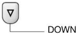
- Press the UP button to raise the temperature. Press the UP button once to increase the set temperature by 1°C.
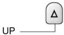
- Press the DOWN button to lower the temperature. Press the DOWN button once to decrease the set temperature by 1°C.
NOTES:
- In the Cooling and Heating mode, the temperature can be set between 16°C and 30°C.
- In Fan Only mode, the temperature cannot be set.
Sleep mode
SLEEP mode can be set in Cooling, Heating or Dry operation mode. This function gives you a more comfortable environment for sleep.

NOTE:
- The appliance will stop operation automatically after operating for 8 hours.
- Fan speed is automatically set at low speed.
- In the Cooling mode, if the current room temperature is below 26°C, the temperature will automatically increase 1°C during the first hour after Sleep control is activated, then remain the same. If room temperature is 26 or above, set temperature will not change.
-
In Heating mode, set temperature will decrease by 3^ at most for 3 hours constantly, then keeps steady.
-
Press MODE to select Cooling, Heating or Dry. NOTE: Sleep control cannot be selected when Fan Only or SMART is selected.
- Press the UP or DOWN button to set the temperature.
- Press SLEEP. After 5 seconds, the lights on the control panel display will dim.
NOTE: The temperature and airflow direction may be adjusted during Sleep control. The fan speed is automatically set to Low speed. After 5 seconds, the lights on the control panel display will dim again.
- To turn off Sleep control, press SLEEP, MODE, FAN, ON/OFF, SUPER or wait 8 hours for Sleep control to turn off automatically.
NOTE: The air conditioner will return to previous settings after Sleep control is turned off.
I FEEL
The temperature sensor built in remote controller is activated. It can sense its surrounding temperature, and transmit the signal back the unit. the unit can adjust the temperature so as to provide maximum comfort.

NOTE: Used to set IFEEL mode operation. Press it once, the IFEEL function will be started. Press it again, the IFEEL function will be shut off. If the IFEEL function can't be shut off, please try to press this button about 5 seconds. Advice to put the remote controller in the place where the indoor unit receive signal easily. Advice to cancel the IFEEL mode so as to save energy when stopping the air conditioner.

DIMMER
Press the DIMMER button to turn off the light and the display in the unit.

NOTE:
- When the light is off, receive signal will turn on the light again.
Clock function
- You can or adjust the real time by pressing CLOCK button

- Using the Up and Down buttons to get the correct time.
- Press CLOCK button again the real time is set.
TIMER ON/OFF
It is convenient to set the timer on with TIMER ON/OFF buttons before you leave so that you will come back to the comfortable room temperature you set.
NOTE: It is real timer control. you should set the CLOCK first.
To TIMER ON
TIMER ON button can be used to turn on the unit automatically at the time you set.
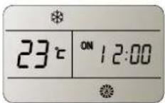
- Press TIMER ON, Then "On 12:00" flashes on the LCD.

- Press the UP or DOWN button, your desired time to turn on the appliance.

Increase

Decrease
- Press the UP or DOWN button once to increase or decrease the time setting by 1 minute.
- Press and hold the UP or DOWN button for 2 seconds to increase or decrease the time setting by 10 minutes.
-
Press and hold the UP or DOWN button for a longer time to increase or decrease the time setting by 1 hour.
-
When your desired time displayed on LCD, press the TIMER ON button to confirm it.
A "Beep" can be heard, "ON" stops flashing. The TIMER indicator on the appliance lights up.
- After your desired time displayed for 5 seconds, the clock will be displayed on the LCD of remote controller instead of the desired time.
To cancel Timer On
Press TIMER ON button again, a "beep" can be heard and the indicator disappears, the TIMER ON mode has been canceled.
NOTE: It is similar to set TIMER OFF, you can make the appliance unit switch off automatically at the time you set.

SWING
Press SWING once to change vertical airflow direction. Press again to stop airflow louver at desired airflow direction.

NOTE:
- Airflow is automatically adjusted to a certain angle in accordance with the operation mode after turning on the unit.
- The direction of airflow can be also adjusted to your own requirement by pressing the SWING button.
- Do not turn the vertical adjustment louvers manually, otherwise malfunctions may occur. if that happens, turn off the unit first and cut off the power supply, then restore power supply again.
Normal Sounds
When your air conditioner is operating normally, you may hear sounds such as:
• Air movement from the fan.
- Clicks from the thermostat cycle.
- Vibrations or noise due to poor wall or window construction.
- A high-pitched hum or pulsating noise caused by the modern high-efficiency compressor cycling on and off.
Draining the Air Conditioner
A. Primary drain cover B. Primary drain plug

WARNING
Excessive Weight Hazard
Use two or more people to move and install air conditioner.
Failure to do so can result in back or other injury.
- Unplug the air conditioner or disconnect power.
- Move the air conditioner to a drain location or outside.
NOTE: To avoid leaking water from the unit, move the air conditioner slowly and keep it level. - Remove the primary drain cover and plug.
- Drain water completely through the drain hole.
- Remove the primary drain cover and plug.
- Drain water completely through the drain hole.
NOTE: If the air conditioner will be stored after use, see "Storing After Use". - Reinstall the drain plug to the primary drain hole.
- Reinstall the primary drain cover to the drain hole.
- Reposition the aor conditioner.
- Plug in the air conditioner or reconnect the power.
- Reinstall the drain plug to the primary drain hole.
- Reinstall the primary drain cover to the drain hole.
- Reposition the aor conditioner.
- Plug in the air conditioner or reconnect the power.
Draining the Air Conditioner(Heating models)
A. Primary drain port
B. Drain hose
C. Primary drain hole
D. Primary drain plug
WARNING: Please connect the drain hose on heating mode, or the unit will stop running after the water the water reaches warning level.
- Uncover the primary drain port.
- Attach the drain hose to the primary drain hose. Make sure the connector has no water leak.
- Place the other end of drain hose into a outfall. Check to see that the hose lies flat and is in the drain. Make sure the hose end that goes to the drain is on a lower level than the hose end that connects to the unit. The hose should not be kinked or pinched.
Cleaning the Outside
- Press ON/OFF to turn off the air conditioner.
- Unplug the air conditioner or disconnect power.
- Remove the air filter and clean separately. See "cleaning the Air Filter".
- Wipe the outside of the air conditioner with a soft, damp cloth.
- Plug in the air conditioner or reconnect power.
- Press ON/OFF to start the air conditioner.
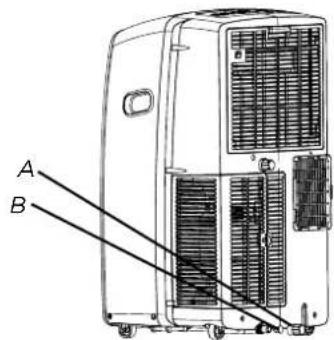
Cleaning the Air Filter
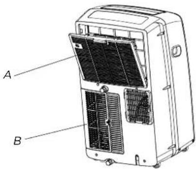
A. Evaporator air intake filter panel door
B. Condenser air intake filter panel door
- Press ON/OFF to turn off the air conditioner.
- Open the filter panel door on the back off the air and remove.
- Remove the tapping screw from the consider air intake filter panel door and remove.
- Use a vacuum cleaner to clean the filter. If the filter in very dirty, wash the filter in warm water with a mild detergent
NOTE: Do not wash the filter in the dishwasher or use any chemical cleaners. - Air dry the filter completely before replacing to ensure maximum efficiency.
- Reattach the air filter to the filter panel door.
- Reinstall the filter panel door and tapping screw.
- Press ON/OFF to start the air conditioner.
Storing After Use
If the air conditioner will not be used for an extended period of time:
1. Drain the water completely. See "draining the Air Conditioner".
2. Run the air conditioner set to Fan Only for approximately 12 hours to dry the air conditioner.
3. Unplug the air conditioner.
1. Drain the water completely. See "draining the Air Conditioner".
2. Run the air conditioner set to Fan Only for approximately 12 hours to dry the air conditioner.
3. Unplug the air conditioner.
Before calling for service, try the suggestions below to see whether you can solve your problem without outside help.
Air conditioner will not operate
WARNING

Electrical Shock Hazard
Plug into a grounded 3 prong outlet.
Do not remove ground prong.
Do not use an adapter.
Do not use an extension cord.
Failure to follow these instructions can result in death, fire, or electrical shock.
- The power supply cord is unplugged.
Plug into a grounded 3 prong outlet. See "electrical Requirements."
- Time-delay fuse or circuit breaker of the wrong capacity is being used.
Replace with a time-delay fuse or circuit breaker of the correct capacity. See “electrical Requirements”.
- A household fuse has blown, or a circuit breaker has tripped.
Replace the fuse, or reset the circuit breaker. See "Electrical Requirements". Air conditioner runs for a short time only, but room is not cool
- The On/Off button has not been pressed.
Press ON/OFF.
• The local power has failed.
Wait for power to be restored.
Air conditioner blows fuses or trips circuit breakers
- Too many appliances are being used on the same circuit.
Unplug or relocate appliances that share the same circuit.
- You are trying to restart the air conditioner too soon after turning off air conditioner.
Wait at least 3 minutes after turning off air conditioner before trying to restart the air conditioner.
- You have changed modes.
Wait at least 3 minutes after turning off air conditioner before trying to restart the air conditioner.
Air conditioner seems to run too much
- Is there a door or window open?
Keep doors and windows closed.
- The current air conditioner replaced an older model.
The use of more efficient components may cause the air conditioner to run longer than an older model, but the total energy consumption will be less. Newer air conditioners do not emit the “blast” of cold air you may be accustomed to from older units, but this is not an indication of lesser cooling capacity or efficiency. Refer to the efficiency rating (EER and capacity rating (in Btu/h) marked on the air conditioner.
- The air conditioner is in a heavily occupied room, or heatproducing appliances are in use in the room.
Use exhaust vent fans while cooking or bathing and try not to use heat-producing appliances during the hottest part of the day. Portable air conditioners are designed as supplemental cooling to local areas within a room. A higher capacity air conditioner may be required, depending on the size of the room being cooled.
Air conditioner runs for a short time only, but room is not cool
- Set temperature is close to room temperature.
Lower set temperature. See "Portable Air Conditioner Use".
Display error code
- If the unit display error code E5, it is water full in the unit, you should drain the water, see "Draining the air conditioner". After draining, you can operate the unit again.
- if the unit display error code E1/E2/E3//E6/E7/EA, please contact customer service.
- The filter is dirty or obstructed by debris. Clean the filter.
• Air outlet is blocked. Clear air outlet..
- Set temperature is too high. Lower set temperature.
Air conditioner cycles on and off too much
- The air conditioner is not properly sized for your room. Check the cooling capabilities of your portable air conditioner
Portable air conditioners are designed as supplemental cooling to local areas within a room.
- The filter is dirty or obstructed by debris. Clean the filter.
- There is excessive heat or moisture open container cooking, showers, etc.) in the room.
Use a fan to exhaust heat or moisture from the room. Try not to use heat-producing appliances during the hottest part of the day.
• The louvers are blocked.
Install the air conditioner in a location where the louvers are free from curtains, blinds, furniture, etc.
UPUTE ZA UPORABU I POSTAVLJANJE
HR
Zahvaljujemo vam na kupnji klimatske naprave. Molimo vas da pažljivo pročitate ove upute za uporabu i postavljanje prije nego što aparat namjestite i počnete koristiti. Korisnički priručnik s uputama sačuvajte, jer ćete ga možda trebati kasnije.
SIGURNOSNE PREDOSTROŽNOSTI 2
DIJELOVI UREĐAJA 10
SIGURNOST KLIMATSKE NAPRAVE 11
ZAHTJEVI U VEZI S POSTAVLJANJEM 11
Alati i dijelovi 11
natural_image
Pure mechanical cross-section diagram without any text, numbers, or symbolsUPOZORENJA za uporabu rashladnog sredstva R290
natural_image
Technical illustration of mechanical components including a cylindrical part, threaded fastener, and ring-like parts (no text or symbols)A. Spužvasta brtva
B. Regulacijska spojnica
C. Fleksibilna odvodna cijev
D. Prozorski regulacijski priključak
E. Vijci 1/2" (2)
F. Vijci za drvo (4)
G. Konzola za zaključavanje prozora (2)
H. Pokrov za kišu
I. Vanjska klizna letva
J. Unutarnja klizna letva
K. Vijci (4)
L. Matice (4)
M. Opružne podloške (4)
N. Obične podloške (4)
O. Pokrov zidnog otvora
P. Adaptacijski priključak odvodne cijevi
Q. Dugi vijci za drvo (3)
R. Plastični klinovi (3)
S. Odvodna cijev za vodu (1) (način za grijanje)
T. Spona odvodne cijevi za vodu (1) (način za grijanje)
NAPOMENE:
- Fleksibilna odvodna cijev omogućuje postavljanje klimatske naprave na udaljenost od 60 do 170 cm od prozora ili vrata. Kod uređaja s dodatnim grijačima, udaljenost od uređaja do najbliže zapaljive površine mora biti najmanje 100 cm.
- Prijenosne klimatske naprave namijenjene su dodatnom hlađenju određenih područja unutar prostorije odnosno sobe.
Okomit klizni prozor
Vodoravan klizni prozor
NAPOMENE:
natural_image
Illustration of a hand holding a coiled tube wrapped in mesh material (no text or symbols)natural_image
Technical line drawing of a coiled spring or hose assembly with labeled components A and B (no text or symbols beyond labels)A. Unutarnja klizna letva
B. Vanjska klizna letva
- Pilom odrežite unutarnju kliznu letvu, tako da se uklapa u prozorski otvor (širinu prozora).
-
Unutarnju kliznu letvu gurnite u vanjsku kliznu letvu kompleta prozorskih kliznih letava.
-
Komplet prozorskih kliznih letava namjestite u prozorski otvor i raširite ga tako da se uklapa u širinu prozora. Provjerite da li se pokrov za kišu nalazi na vanjskoj strani prozora.


NAPOMENA: Kod montaže na prozor z prozorskim krilom, komplet prozorskih kliznih letava možete montirati okomito, tako da se komplet prozorskih kliznih letava otvara na dnu.
natural_image
Diagram showing two views of a door with arrows indicating direction, no text or symbols presentnatural_image
Illustration of a coiled tube being handled with two hands (no text or symbols)natural_image
Technical line drawing of a coiled pipe or duct assembly with labeled components A and B (no text or symbols beyond labels)natural_image
Illustration of a portable air conditioner unit with a hose inserted into a textured wall (no text or symbols)Zidni adaptacijski priključak za odvodnu cijev umetnite u zidni nastavak/rozetu.
- Odstranite zidni adaptacijski priključak sa zidnog nastavka/rozete.
- Zatvorite zidni nastavak pokrovom.

natural_image
Two circular objects connected by a line on a textured background (no text or symbols)Pokrov
Uporaba lokalne klimatske naprave
Pravilnom uporabom vaše klimatske naprave dobiti ćete najbolje moguće rezultate.
natural_image
Illustration of hands using a tool to adjust or install a component, enclosed in a circle (no text or symbols)NAPOMENA:
- Pritiskom na tipku 'nadolje'(DOWN) smanjujete temperaturu. Pritisnuvši tipku 'NADOLJE' (DOWN) jednom, smanjujete ugođenu temperaturu za 1 °C.
NAPOMENE:
- U načinu za hlađenje i grijanje temperaturu možete ugoditi u rasponu od 16 °C do 30 °C.
- U načinu "samo ventilator" temperaturu nije moguće regulirati.
VREMENSKI OGRANIČEN RAD - FUNKCIJA "SLEEP"
natural_image
Simple line drawing of a trash bin with diagonal lines crossing through it (no text or symbols)PLAN 2: (volitelné)

natural_image
Technical illustration of mechanical components including a cylindrical component, ring, and fasteners (no text or symbols)natural_image
Illustration of two hands holding a coiled tube or pipe (no text or symbols visible)natural_image
Technical line drawing of a coiled pipe or hose assembly with labeled components A and B (no text or symbols beyond labels)natural_image
Pure technical diagram showing two views of a door or cabinet with directional arrows indicating movement (no text or symbols)natural_image
Illustration of a hand holding a coiled tube wrapped in mesh, with no text or symbols present.natural_image
Technical line drawing of a coiled pipe with labeled components A and B (no text or symbols beyond labels)natural_image
Illustration of a portable air conditioner unit with a coiled hose inserted, showing airflow direction (no text or symbols)natural_image
Two circular objects on a textured background, one with a diagonal line and the other with a horizontal line (no text or symbols)Kryt
natural_image
Illustration showing two hand tools in a tool, one being inserted and the other holding a grip (no text or symbols present)natural_image
Illustration of hands holding a tool with an arrow indicating direction (no text or symbols)POZNÁMKY:
Indication symbols on LCD:
When your air conditioner is operating normally, you may hear sounds such as:
• Air movement from the fan.
- Clicks from the thermostat cycle.
- Vibrations or noise due to poor wall or window construction.
- A high-pitched hum or pulsating noise caused by the modern high-efficiency compressor cycling on and off.

natural_image
Simple line drawing of a trash bin with diagonal lines crossing through it (no text or symbols)Część grzbietowa
natural_image
Technical illustration of mechanical components including a cylindrical part, ring, and fasteners (no text or symbols)natural_image
Illustration of a hand holding a coiled tube with mesh insulation (no text or symbols)natural_image
Technical line drawing of a coiled spring or hose assembly with labeled components A and B (no text or symbols beyond labels)natural_image
Diagram showing two views of a mechanical or fluid system with arrows indicating direction (no text or symbols)natural_image
Diagram showing two views of a door with arrows indicating direction, no text or symbols presentnatural_image
Illustration of a hand pulling a cylindrical object with a rectangular frame, no text or symbols presentnatural_image
Technical line drawing of a coiled pipe with labeled components A and B (no text or symbols beyond labels)natural_image
Illustration of a portable air conditioner unit with a hose inserted, showing airflow direction (no text or symbols)natural_image
Two circular objects connected by a line, placed on a textured background (no text or symbols)Pokrywa
natural_image
Illustration showing two hand tools in circular frames, one with a magnified view of the device (no text or symbols)natural_image
Illustration of hands using a tool to adjust or install a component, enclosed in a circle (no text or symbols)• UWAGA:
Air conditioner will not operate
OSTRZEŻENIE

natural_image
Pure mechanical cross-section diagram without any text, numbers, or symbolsDÔLEŽITÉ BEZPEČNOSTNÉ POKYNY
USCHOVAJTE SI TENTO NÁVOD
LIKVIDÁCIA JEDNOTKY
OBRÁZOK 2: (volitel'ny)

natural_image
Technical illustration of mechanical components including a cylindrical part, threaded fastener, and ring-like parts (no text or symbols)natural_image
Illustration of two hands holding a coiled cylindrical object with mesh texture, enclosed in a transparent frame (no text or symbols)natural_image
Technical line drawing of a coiled pipe or hose assembly with labeled components A and B (no text or symbols beyond labels)natural_image
Diagram showing two views of a mechanical or fluid system with arrows indicating direction (no text or symbols)natural_image
Diagram showing two views of a door with arrows indicating direction, no text or symbols presentnatural_image
Illustration of a coiled tube being handled with two hands (no text or symbols)natural_image
Illustration of a portable air conditioner unit with a coiled hose inserted, showing airflow direction (no text or symbols)natural_image
Two circular objects on a textured background, one with a diagonal line and the other horizontally, no text or symbols present.Kryt
natural_image
Illustration showing two hand tools in a tool, one being inserted and the other holding a grip (no text or symbols present)-
Vložte nové batérie a dbajte pritom na polaritu (+) a (-).
-
Kryt zasuňte na miesto.

natural_image
Illustration of hands using a tool to interact, enclosed in a circle (no text or symbols)POZNÁMKA:
- Použite 2 batérie LR03 AAA(1.5V). Nepouživajte dobíjateľné batérie. Ked' displej stmavne alebo po 6 mesiacoch vymeňte batérie za nové rovnakého typu.
 | [KWW6] | ON/OFF |  |  | SLEEP | |
 |  | MODE |  | [CGWC] | IFEEL | |
 |  | FAN |  |  | CLOCK | |
| | UP | | [3AZ0] | Timer Off | |
 |  | DOWN |  |  | Timer On | |
 |  | SMART |  |  | SUPER | |
| [XX45] |  | SWING |  |  | DIMMER |
Indikačné symboly
natural_image
Pure mechanical cross-section diagram without any text, numbers, or symbolsHátul
natural_image
Technical illustration of mechanical components including a cylindrical part, threaded fastener, and ring-like parts (no text or symbols)A Tömítőszalag
B Csatlakozó
natural_image
Illustration of two hands holding a coiled cylindrical object with mesh texture (no text or symbols)natural_image
Diagram showing two views of a mechanical or fluid system with arrows indicating direction (no text or symbols)natural_image
Diagram showing two views of a door with arrows indicating direction, no text or symbols presentnatural_image
Illustration of a hand pulling a cylindrical object with a transparent frame (no text or symbols)natural_image
Technical line drawing of a coiled pipe with labeled components A and B (no text or symbols beyond labels)natural_image
Illustration of a portable air conditioner unit with a coiled hose inserted, showing airflow direction (no text or symbols)natural_image
Two circular objects on a textured background, one with a diagonal line and the other with a horizontal line (no text or symbols)Takaró lap