
SGC-8000N - Vibratory plate STANLEY - Free user manual and instructions
Find the device manual for free SGC-8000N STANLEY in PDF.


| Product Type | Vibratory Plate |
| Brand | Stanley |
| Model | SGC-8000N |
| Overall Dimensions (L x W x H) | 1120 x 560 x 970 mm |
| Operating Weight | 800 kg |
| Engine Type | 4-Stroke Gasoline Engine |
| Engine Power | 7.5 kW (10.0 HP) |
| Centrifugal Force | 80 kN |
| Vibration Frequency | 60 Hz (3600 vpm) |
| Plate Size (Width x Length) | 560 x 800 mm |
| Compaction Depth | Up to 600 mm |
| Travel Speed | 0 - 25 m/min |
| Fuel Tank Capacity | 8.5 L |
| Water Tank Capacity | 15 L |
| Starting System | Recoil Starter & Electric Start |
| Safety Features | Emergency Stop Switch, Deadman Handle |
| Maintenance | Air filter cleaning every 25 hours, oil change every 100 hours |
| Warranty | 2 years limited warranty |
| Included Accessories | Tool kit, Owner's manual |
Frequently Asked Questions - SGC-8000N STANLEY
User questions about SGC-8000N STANLEY
0 question about this device. Answer the ones you know or ask your own.
Ask a new question about this device
Download the instructions for your Vibratory plate in PDF format for free! Find your manual SGC-8000N - STANLEY and take your electronic device back in hand. On this page are published all the documents necessary for the use of your device. SGC-8000N by STANLEY.
USER MANUAL SGC-8000N STANLEY
GB Original instructions
Manufactured under license by:
Stanley® is a registered trademark of The Stanley Works or its affiliates and is used under license.

Your new Vibratory Plate Compactor will more than satisfy your expectations. It has been manufactured under stringent quality standards to meet superior performance criteria. You will find it easy and safe to operate, and with proper care, it will give you many years of dependable service.
Carefully read through this entire operator's manual before using your new Plate Compactor. Take special care to heed the cautions and warnings
The commitment to quality has been designed into details: reinforced self-cleaning base plate, engine oil drain hose, closed V-belt guard, self-adjusting centrifugal clutch and folding handle. A range of useful accessories enables use in all kinds of applications.
The Plate Compactor applies energy to the loose soil or other materials to increase its density and load bearing capacity, mainly used for small repair and maintenance work. The loose soil or particles are moved or rearranged in a particular manner close to each other to avoid any trapped air or voids. It increases the load bearing capacity, decreases water seepage, prevents soil settlement, reduces swelling, contraction of the soil and prevents frost damage. It is ideal for compaction of granular soils, sands, gravel, crushed aggregate and mixed soils.
Specifications
SGC-8000N
| Plate Size | 495 X 380 mm |
| Centrifugal Force | 8200 N |
| Exciter Speed | 5900 rpm |
| Travel Speed | 25m/min |
| Engine | 79 cc |
| Operation Weight | 51.5 kg |
| Drive engine design: | |
| Single-cylinder forced air-cooled 4-stroke OHV | |
| Fuel type: | Normal unleaded petrol |
| Tank capacity: | 1.6 l |
| Engine oil: | 0.6 l (15W40/<0 °C: 5W30) |
| spark plug: | F7RTC |
| electrode spacing: | 0.7-0.9mm |
| engine power: | 1,5 kW |
| Vibration level : | 15.3m/s2,K=1,5m/s2 |
| sound power level : | 100.4dB(A),K=2,47dB(A) |
| sound pressure level : | 80.4dB(A),K=2,47dB(A) |
| Guranteed sound power: | 104 dB (A) |
SGC-11000N/SGC-11000N-T
| Plate Size | 515 X 390 mm |
| Centrifugal Force | 11000 N |
| Exciter Speed | 5500 rpm |
| Travel Speed | 25m/min |
| Engine | 196 cc |
| Operation Weight | 59 kg / 65 kg |
| Drive engine design: | |
| Single-cylinder forced air-cooled 4-stroke OHV | |
| Fuel type: | Normal unleaded petrol |
| Tank capacity: | 3.6 l |
| Engine oil: | 0.6 l (15W40/<0 °C: 5W30) |
| spark plug: | F7RTC |
| electrode spacing: | 0.7-0.9mm |
| engine power: | 4,8 kW |
| Vibration level : | 14.5m/s ^2 ,K=1,5m/s ^2 |
| sound power level : | 100.6dB(A),K= 2,47dB(A) |
| sound pressure level : | 80.6dB(A), K= 2,47dB(A) |
| Guranteed sound power: | 105 dB (A) |
SGC-13000N/SGC-13000N-T
| Plate Size | 520x445 mm |
| Centrifugal Force | 13000 N |
| Exciter Speed | 5500 rpm |
| Travel Speed | 15m/min |
| Engine | 196 cc |
| Operation Weight | 79,5 kg / 84 kg |
| Drive engine design: | |
| Single-cylinder forced air-cooled 4-stroke OHV | |
| Fuel type: | Normal unleaded petrol |
| Tank capacity: | 3.6 l |
| Engine oil: | 0.6 l (15W40/<0 oC: 5W30) |
| spark plug: | F7RTC |
| electrode spacing: | 0.7-0.9mm |
| engine power: | 4,8 kW |
| Vibration level : | 15.8 m/s^2, K=1,5m/s^2 |
| sound power level : | 100.3dB(A), K= 2,47dB(A) |
| sound pressure level : | 80.3dB(A), K= 2,47dB(A) |
| Guranteed sound power: | 105 dB (A) |
G B
SYMBOLS
The rating plate on your machine may show symbols. These represent important information about the product or instructions on its use.

Read these instructions for use carefully.

Wear eye protection. Wear hearing protection.

Wear protective gloves.

Wear safety footwear.

It is forbidden to remove or tamper with the protection devices and safety devices.

Keep away from rotating parts.

Do not touch parts which are hot from operation. Serious burns may result.

Do not smoke or have open flames. Use extreme caution when storing, handling and using fuels, as they are highly volatile and explosive in vapor state.

Keep children and bystanders off and away.
This plate compactor is not intended for use by persons (including children) with reduced physical, sensory or mental capabilities, or lack of experience
and knowledge, unless they have been given supervision or instruction concerning the use of the appliance by a person responsible for their safety.
SAFETY
General Safety Rules
Understand your Machine
Read and understand the operator's manual and labels affixed to the machine. Learn its application and limitations as well as the specific potential hazards peculiar to it. Be thoroughly familiar with the controls and their proper operation. Know how to stop the machine and disengage the controls quickly. Make sure to read and understand all the instructions and safety precautions as outlined in the Engine Manual, packed separately with your unit. Do not attempt to operate the machine until you fully understand how to properly operate and maintain the Engine and how to avoid accidental injuries and/or property damage.
Work area
Never start or run the engine inside a closed area. The exhaust fumes are dangerous, containing carbon monoxide, an odorless and deadly gas. Operate this unit only in a well ventilated outdoor area.
Never operate the machine without good visibility or light.
Personal safety
Do not operate the machine while under the influence of drugs, alcohol, or any medication that could affect your ability to use it properly. Dress properly. Wear heavy long pants, boots and gloves. Do not wear loose clothing, short pants, jewelry of any kind. Secure long hair so it is above shoulder level. Keep your hair, clothing and gloves
away from moving parts. Loose clothes, jewelry or long hair can be caught in moving parts.
Check your machine before starting it. Keep guards in place and in working order. Make sure all nuts, bolts, etc. are securely tightened.
Never operate the machine when it is in need of repair or is in poor mechanical condition. Replace damaged, missing or failed parts before using it. Check for fuel leaks. Keep the machine in safe working condition Do not use the machine if the engine's switch does not turn it on or off. Any gasoline powered machine that can not be controlled with the engine switch is dangerous and must be replaced.
Form a habit of checking to see that keys and adjusting wrenches are removed from machine area before starting it. A wrench or a key that is left attached to a rotating part of the machine may result in personal injury.
Stay alert, watch what you are doing and use common sense when operating the machine.
Do not overreach. Do not operate the machine while barefoot or when wearing sandals or similar lightweight footwear. Wear protective footwear that will protect your feet and improve your footing on slippery surfaces.
Keep proper footing and balance at all times. This enables better control of the machine in unexpected situations.
Avoid accidental starting. Be sure the engine's switch is off before transporting the machine or performing any maintenance or service on the unit. Transporting or performing maintenance or service on a machine with its switch on invites accidents.
Fuel safety
Fuel is highly flammable, and its vapors can explode if ignited. Take precautions when using to reduce the chance of serious personal injury. When refilling or draining the fuel tank, use an approved fuel storage container while in a clean, well-ventilated outdoor area. Do not smoke, or allow sparks, open flames or other sources of ignition near the area while adding fuel or operating the unit. Never fill fuel tank indoors.
Keep grounded conductive objects, such as tools, away from exposed, live electrical parts and connections to avoid sparking or arcing. These events could ignite fumes or vapors. Always stop the engine and allow it to cool before filling the fuel tank. Never remove the cap of the fuel tank or add fuel while the engine is running or when the engine is hot. Do not operate the machine with known leaks in the fuel system.
Loose the fuel tank cap slowly to relieve any pressure in the tank.
Never overfill fuel tank (there should be no fuel above the upper limit mark).
Replace all fuel tank and container caps securely and wipe up spilled fuel. Never operate the unit without the fuel cap securely in place.
Replace all fuel tank and container caps securely and wipe up spilled fuel. Never operate the unit without the fuel cap securely in place.
Avoid creating a source of ignition for spilled fuel. If fuel is spilled, do not attempt to start the engine but move the machine away from the area of spillage and avoid creating any source of ignition until fuel vapors have dissipated.
Store fuel in containers specifically designed and approved for this purpose.
Store fuel in a cool, well-ventilated area, safely away from sparks, open flames or other sources of ignition.
G B
Never store fuel or machine with fuel in the tank inside a building where fumes may reach an spark, open flame, or any other source of ignition, such as a water heater, furnace, clothes dryer and the like. Allow the engine to cool before storing in any enclosure.
Machine use and care
Never pick up or carry a machine while the engine is running.
Do not force the machine. Use the correct machine for your application. The correct machine will do the job better and safer at the rate for which it was designed.
Do not change the engine governor settings or over-speed the engine. The governor controls the maximum safe operating speed of the engine.
Do not run the engine at a high speed when you are not pounding.
Do not put hands or feet near rotating parts.
Avoid contact with hot fuel, oil, exhaust fumes and hot surfaces. Do not touch the engine or muffler. These parts get extremely hot from operation. They remain hot for a short time after you turn off the unit. Allow the engine to cool before doing maintenance or making adjustments.
If the machine should start to make an unusual noise or vibration, immediately shut off the engine, disconnect the spark plug wire, and check for the cause. Unusual noise or vibration is generally warning of trouble.
Use only attachments and accessories approved by the manufacturer. Failure to do so can result in personal injury.
Maintain the machine. Check for misalignment or binding of moving parts, breakage of parts and any other condition that may affect the machine's operation. If damaged, have the
machine repaired before use. Many accidents are caused by poorly maintained equipment.
Keep the engine and muffler free of grass, leaves, excessive grease or carbon build up to reduce the chance of a fire hazard.
Never douse or squirt the unit with water or any other liquid. Keep handles dry, clean and free from debris. Clean after each use.
Observe proper disposal laws and regulations for gas, oil, etc. to protect the environment.
Store idle machine out of the reach of children and do not allow persons unfamiliar with the machine or these instructions to operate it. Machine is dangerous in the hands of untrained users.
Service
Before cleaning, repair, inspecting, or adjusting, shut off the engine and make certain all moving parts have stopped. Always make sure the engine's switch is in its "OFF" position. Disconnect the spark plug wire, and keep the wire away from the plug to prevent accidental starting.
Have your machine serviced by a qualified repair personnel using only identical replacement parts. This will ensure that the safety of the machine maintained.
Specific Safety Rules
To avoid injury, keep hands, fingers and feet away from the base plate. Grip the handle of the plate compactor firmly with both hands. If both hands are holding the handle and your feet are clear of the compactor base, your hands, fingers and feet can not be injured by the compactor base.
Always operate the machine from behind, never pass or stand in front of the machine when the
engine is running.
Never place tools or any other item under the plate compactor.
If the unit strikes a foreign object, stop the engine, disconnect the spark plug, thoroughly inspect the machine for any damage, and repair the damage before restarting and operating the machine.
Do not overload the machine capacity by compacting too deep in a single pass or at too fast a rate.
Never operate the unit at high transport speeds on hard or slippery surfaces.
Exercise extreme caution when operating on or crossing gravel drives, walks, or roads. Stay alert for hidden hazards or traffic. Do not carry passengers.
Never leave the operating position and leave the plate compactor unattended when the engine is running.
Always stop the engine when compacting is delayed or when walking from one location to another.
Stay away from the edged of ditches and avoid actions that may cause the plate compactor to topple over.
Always ascend slopes carefully, in a direct path and in reverse to present the plate compactor from toppling over onto the operator.
Always park the unit on a firm and level surface and shut the tool off.
To reduce exposure to vibration, limit the hours of operation and take periodic breaks to minimize repetition and rest your hand. Reduce the speed and force in which you do the repetitive movement. Try to fill each day
with jobs where operating hand-held power equipment is not required.
CONTENTS SUPPLIED
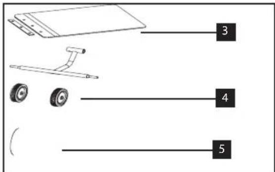
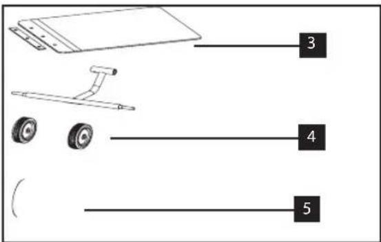
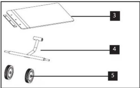
The plate compactor comes partially assembled and is shipped in carefully packed carton. After all the parts have been removed from the carton, you should have:
Basic Models
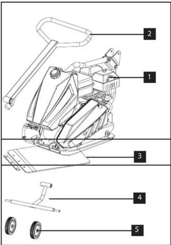
- Plate Compactor Chassis with Engine and Transmission
- Handle
- Paving Pad
- Foldings Wheels Bracket
- Wheels
ASSEMBLY
Following the assembly directions below, you will assemble the plate compactor in a few minutes.
Handle

Mount the handle to the chassis with the M10X95 bolt, washers and nut.

natural_image
Technical line drawing of a mechanical device labeled SGC-8000N, showing lever and base components without any readable text or symbols.- Turn over the lower handle.
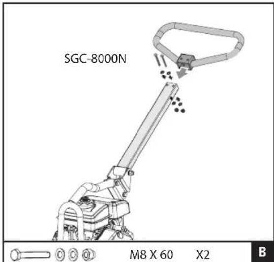
- Mount the upper handle to the lower handle with 2 M8X60 bolts, washers and nuts.
Throttle Control
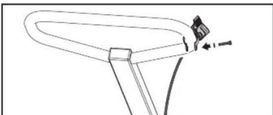
natural_image
Line drawing of a bicycle handle with a small inset showing a gear shift (no text or symbols)Fix the throttle control to the upper handle as shown.
Folding Wheels Kit

- Slide the wheels over the stub axles. Secure with hairpin retainers and flat washers.

- Three holes on the stub axle allow to adjust the distance between the wheels, pull out the pin first, adjust the wheels to the suitable distance, then tighten with the pin.
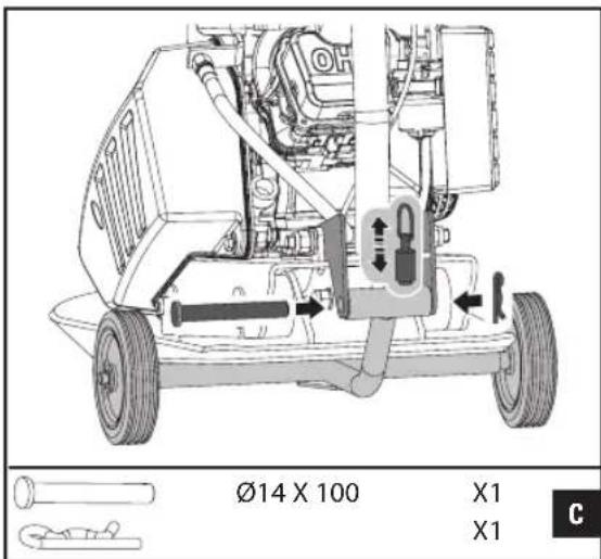
- Pull up the spring bolt and put the upper pipe of the wheels bracket into the mounting bracket. Align two ends of the pipe with the holes. Slide the bolt in and secure with the clips.
Paving Pad Kit
The transparent rubber Paving Pad allows to compact concrete paving slabs, stones, bricks and blocks silently and gently.

natural_image
Technical line drawing of a mechanical robotic arm with mounting base and lever mechanism (no text or symbols)Attach the Paving Pad onto the Base Plate as shown. Align the holes in the Base Plate, Paving Pad and Clamp Plates, and secure it with 3 bolts M10x30 and lock washers. (Only 2 bolts and lock washers for SGC-8000N.)
Engine Oil

OIL HAS BEEN DRAINED FOR SHIPPING.
Failure to fill engine sump with oil before starting engine will result in permanent damage and void engine warranty.
Add oil according to Engine Manual packed separately with your tiller.
G
B

Part list
- Throttle Control
- Lift Handle
- Air Cleaner
- Fuel Tank
- Handle
- Muffler
- Belt Guard
- Oil Drain Hose
- Exciter
- Base Plate
- Optional water sprinkler kit (SGC-11000N-T; SGC-13000N-T)
KNOW YOUR MACHINE
Features and Controls
Fuel Valve Control
The fuel valve opens and closes the passage between the fuel tank and the carburetor. The fuel valve lever must be in the ON position for the engine to run. When the engine is not in use, leave the fuel valve lever in the OFF position to prevent carburetor flooding and to reduce the possibility of fuel leakage.
Throttle Control
The throttle lever controls engine speed. Moving the throttle lever makes the engine run faster or slower.
Engine Switch
The engine switch enables and disables the ignition system. The engine switch must be in the ON position for the engine to run. Turning the engine switch to the OFF position stops the engine.
Choke Lever
The choke lever opens and closes the choke valve in the carburetor. The closed position enriches the fuel mixture for starting a cold engine. The open position provides the correct fuel mixture for operation after starting, and for restarting a warm engine. Some engine applications use a remotely-mounted choke control rather than the engine-mounted choke lever.
Recoil Starter Grip
Pulling the starter grip operates the recoil starter to crank the engine.
Oil Drain Hose

Running the engine with dirty oil can cause premature engine wear and failure. Changing oil regularly is extremely important. The flexible oil drain hose is equipped to drain oil into appropriate receptacle.
Exciter
An eccentric weight mounted on the exciter shaft contained within exciter housing is driven at high speed by a clutch and belt drive system. This high speed shaft revolution causes the rapid lifting and downward ramming motion of the machine as well as imparting a forward motion.
Compactor Operation
Adding fuel
Fill the fuel tank as instructed in the separate Engine Manual packed with the Plate Compactor.
More detailed description of the engine operation and all related precautions and procedures can be found in the Engine Manual packed separately with the unit.
G B
Starting Engine
- Move the fuel valve lever to the ON position.
- To start a cold engine, move the choke to the CLOSE position.
To restart a warm engine, leave the choke lever in the OPEN position. - Move the throttle lever away from the SLOW position, about 1/3 of the way toward the FAST position.
- Turn the engine switch to the ON position.
- Operate the starter
Operating
Do not operate plate on concrete or on extremely hard, dry, compacted surfaces.
The plate will jump rather than vibrate and could damage both plate and engine.
-
After engine warms up, pull throttle lever to accelerate engine speed. Plate will begin vibrating and move forward.
-
The plate compactor is designed to run at an engine speed (engine take off shaft) of 3600 rpm (Normally considered full throttle). Running the engine at lower rpm's will result in a decrease of compaction force and lower travel speed. It will create excessive "out-of-synch" vibrations resulting in poor compaction, maneuverability, excessive wear to the machine, and discomfort to the operator.
-
In operation, guide the machine, but let the compactor do the work. Bearing down on the handle is unnecessary and causes shock absorber wear.
-
On level surfaces the compactor moves forward rapidly. On uneven surfaces or inclines, light forward pressure on handle may be required to assist the compactor in moving forward.
-
The number of passes required to reach a desired compaction level will depend
on the type and moisture content of soil. Maximum soil compaction has been reached when excessive kickback is noticed.
When using a compactor on asphalt, Water Sprinkler Kit is required to help prevent the bottom plate from adhering to the hot asphalt surface.
When using plate on paving stones, attach a pad to the bottom of the plate to prevent chipping or grinding surface of the stones. A special urethane pad designed for this purpose is available as an optional accessory.
While a certain amount of moisture in the soil is necessary, excessive moisture may cause soil particles to stick together and prevent good compaction. If soil is extremely wet, allow it to dry somewhat before compacting.
If soil is so dry as to create dust clouds while operating plate, some moisture should be added to the ground material to improve compacting. This will also reduce service to the air filter.
Stopping Engine
To stop the engine in an emergency, simply turn the engine switch to the OFF position. Under normal conditions, use the following procedure.
- Move the throttle lever to the SLOW position.
- Let engine idle for one or two minutes.
- Turn the engine switch to the OFF position.
- Turn the fuel valve lever to the OFF position.
Do not move choke control to CLOSE to stop engine. Backfire or engine damage may occur.
Idle Speed
Set throttle control lever to its "low" position to reduce stress on the engine when compacting is not being performed. Lowering the engine speed to idle the engine will help extend the life of the engine, as well as conserve fuel and reduce the noise level of the machine.
MAINTENANCE
Maintaining your compactor will insure long life to the machine and its components.
Preventive Maintenance
- Turn off engine. Engine must be cool.
- Keep the engine's throttle lever in its SLOW position, and remove spark plug wire from spark plug and secure.
- Inspect the general condition of the plate compactor. Check for loose screws, misalignment or binding of moving parts, cracked or broken parts, and any other condition that may affect its safe operation.
- Remove all debris from the plate compactor with a soft brush, vacuum, or compressed air. Then use a premium quality lightweight machine oil to lubricate all moving parts.
- Clean the bottom of the compactor base as soon as it begins to pick up soil being compacted. The unit can not do a good job if the bottom surface is not smooth and clean.
- Replace spark plug wire.
Never use a "pressure washer" to clean your plate compactor. Water can penetrate tight areas of the unit and cause damage to spindles, pulleys, bearings, or the engine. The use of pressure washers will result in shortened life and reduce serviceability.
Checking V-Belt(s)
To ensure optimum power transmission from the engine to the eccentric shaft, the V-belt(s) must be in good condition and operate under proper tension.
- Turn off engine. Engine must be cool.
- Remove the belt guard to access the V-belt(s).
- Check the condition of the V-belt(s). If any V-belt is cracked, frayed, or glazed, it should be replaced as soon as convenient.
- Check the V-belt tension by squeezing them in the center. The normal deflection on each side should be 9mm (3/8" to 13mm (1/2" with moderate pressure from your thumb or finger.
On new machines or after installing a new belt, check belt tension after first 20 hours of operation. Check and adjust belt every 50 hours thereafter.
Tensioning V-Belt
Proper belt tension is critical to good performance. Proper adjustment will assure long belt life. Too much or too little belt tension will cause premature belt failure.
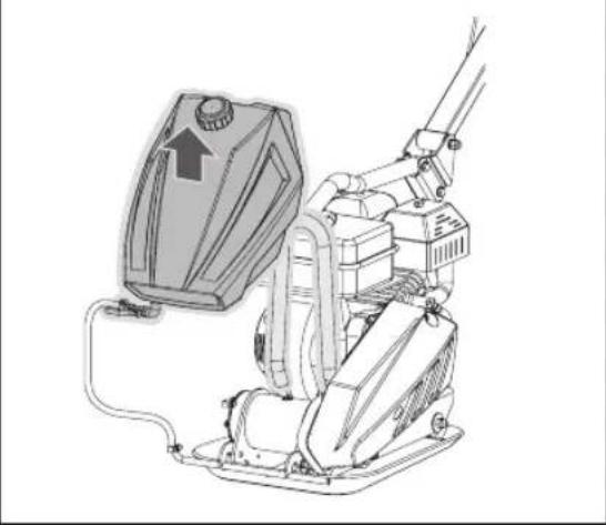
Compactor with optional water sprinkler kit
natural_image
Technical line drawing of a mechanical device with no visible text or symbols- If the plate compactor you bought is with water tank, please pull the water tank up from the chassis as shown.
G B
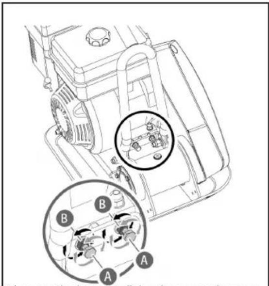
- Loosen the jam nuts B, leaving enough space between the nut and bracket.
by turning the adjustment bolts A to remove any slack in V-belt(s).
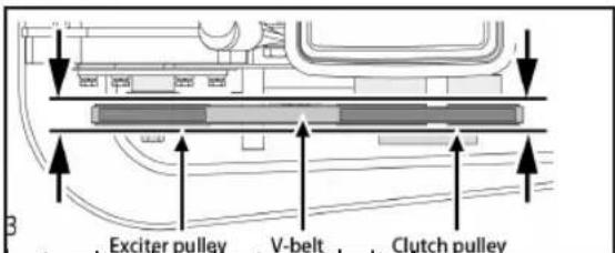
When adjusting the belt(s), make sure that the clutch pulley is in alignment with exciter pulley.

- When the V-belt tension is correct,
tighten
the jam nuts B against the bracket.
-
Tighten the engine mount bolts.
-
Replace the belt guard.
If the adjustment bolts have no more adjustment left, the belt(s) may have to be replaced.
Replacing V-Belt(s)
Both V-belts should be replaced at the same time because they will wear evenly through normal use. Work on one belt at a time.
-
Loose 4 engine mount bolts (do not remove) only enough to move the engine forward.
-
Loosen the jam nuts B and bolts A shown in above figure.
-
Slide the engine toward the front of plate and slip the old V-belt(s) off of the wheel pulley and install the new V-belt(s) in their place.
-
Position the V-belt(s) over the engine pulley.
-
Move the engine back.

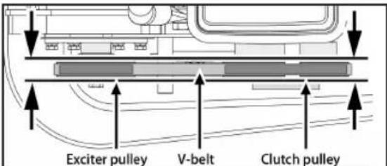
When adjusting the belt(s), make sure that the clutch pulley is in alignment with exciter pulley.
-
When the V-belt tension is correct, tighten the jam nuts B and the engine mount bolts.
-
Replace the belt guard.
When removing or installing the drive belt(s), be careful not to get your fingers caught between the belt and pulley.
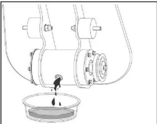
- Let exciter cool before changing exciter oil.

natural_image
Technical line drawing of a mechanical device with labeled components and directional arrows (no text or symbols)- Remove the belt guard and V-belt.
- Remove the bolts that hold the deck to the housing.
- Lift entire deck with engine from housing.
natural_image
Technical line drawing of a mechanical device with a bowl of liquid and a droplet falling into it (no text or symbols)- Remove pipe plug from top of exciter housing. Tilt housing upside down so oil drains from exciter. Examine oil for metal chips as a precaution to future problems.
- Return plate housing to the upright position.

- Fill the exciter housing with exciter oil.

Do not overfill - overfilling can result in excessive temperatures in the exciter.
- Apply pipe sealant to pipe plug and reinstall into top of exciter housing.
- Reinstall deck, V-belt(s) and belt guard.
STORAGE
If the plate compactor will not be used for a period longer than 30 days, following the steps below to prepare your unit for storage.
- Drain the fuel tank completely. Stored fuel containing ethanol or MTBE can start to go stale in 30 days. Stale fuel has high gum content and can clog the carburetor and restrict fuel flow.
- Start the engine and allow it to run until it stops. This ensures no fuel is left in the carburetor. Run the engine until it stops. This helps prevent deposits from forming inside the carburetor and possible engine damage.
- While the engine is still warm, drain the oil from the engine. Refill with fresh oil of the grade recommended in the Engine Manual.
G B
- Allow the engine to cool. Remove the spark plug and put 60 ml of SAE-30 high quality motor oil into the cylinder. Pull the starter rope slowly to distribute the oil. Replace the spark plug.

Remove the spark plug and drain all of the oil from the cylinder before attempting to start the unit after storage.
- Use clean cloths to clean off the outside of the compactor and to keep the air vents free of obstructions.

Do not use strong detergents or petroleum based cleaners when cleaning plastic parts. Chemicals can damage plastics.
natural_image
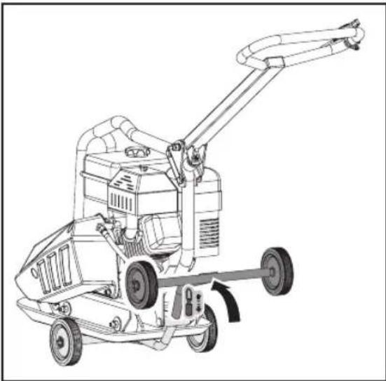
Line drawing of a manual harvester with a rotating arm and wheels (no text or symbols)- Pull up the spring bolt and fold up the wheels bracket.
natural_image
Technical line drawing of a cleaning or cleaning machine with no visible text or symbols-
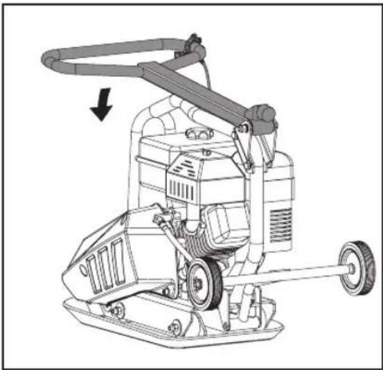
Carefully fold the handle down. Do not allow control cables to become pinched or bent.
-
Store your plate compactor in upright position in a clean, dry building that has good ventilation.
LIFTING/TRANSPORTING
See technical data for the weight of the machine.
To avoid burns or fire hazards, let engine cool before lifting / transporting machine or storing indoors.

natural_image
Line drawing of a mechanical power tool with wheels and a crane (no text or symbols)The unit must be transported in the upright position to prevent fuel from spilling. Do not lay machine on its side or top.
Secure or tie down unit using the lifting handle to prevent machine from sliding or tipping over.

Machine may fall and cause damage or injury if lifted incorrectly. Lift using handles at base of plate.
ENVIRONMENTAL

Recycle unwanted materials instead of disposing of them as waste. All tools, hoses and packaging should be resorted, taken to the local recycling center and disposed of in an environmentally safe way.
TROUBLESHOOTING
| PROBLEMS CAUSES Remedy | ||
| Engine fails to start. 1. Spark | plug wire disconnected.2. Out of fuel or stale fuel.3. Throttle control lever not in correct starting position.4. Choke not in ON Position.5. Blocked fuel line.6. Fouled spark plug.7. Engine flooding. | 1. Attach spark plug wire securely to spark plug.2. Fill with clean, fresh gasoline.3. Move throttle control lever to start position.4. Throttle must be positioned at choke for a cold start.5. Clean the fuel line.6. Clean, adjust gap, or replace.7. Wait a few minutes to restart, but do not prime. |
| Engine runs erratically. | 1. Spark plug wire loose.2. Unit running on CHOKE.3. Blocked fuel line or stale fuel.4. Vent plugged.5. Water or dirt in fuel system.6. Dirty air cleaner. | 1. Connect and tighten spark plug wire.2. Move choke lever to OFF.3. Clean fuel line. Fill tank with clean, fresh gasoline.4. Clear vent.5. Drain fuel tank. Refill with fresh fuel.6. Clean or replace air cleaner. |
| Engine overheats. 1. Engine | oil level low.2. Dirty air cleaner.3. Air flow restricted | 1. Fill crankcase with proper oil.2. Clean air cleaner.3. Remove blower housing and clean. |
| Engine will not stop when throttle control is positioned at stop, or engine speed does not increase properly when throttle control is adjusted. | Debris interfering with throttle linkage. | Clean dirt and debris. |
| Compactor is difficult to control when pounding (machine jumps or lurches forward) | Too high engine speed on hard ground. | Set the throttle lever at lower speed. |
EINFÜHRUNG
Vibration: 15.8m/s^2, K=1,5m/s^2

natural_image
Technical line drawing of a mechanical device labeled SGC-8000N, showing a lever mechanism (no text or symbols on the diagram itself)natural_image
Line drawing of a bicycle wheel with a handle and seat, showing no text or symbolsnatural_image
Technical line drawing of a robotic arm with mounting base and chain, no text or symbols presentTeileliste
natural_image
Technical line drawing of a mechanical device with exploded view and mounting features (no text or symbols)natural_image
Technical line drawing of a mechanical assembly with a container and pouring liquid (no text or symbols)natural_image
Line drawing of a manual agricultural harvester with a rotating arm and wheels (no text or symbols)D
natural_image
Line drawing of a mechanical cleaning or cleaning machine with wheels and a downward arrow indicating motion (no text or symbols)natural_image
Line drawing of a mechanical robotic device with wheels and a control panel (no text or symbols)100.3dB (A), K = 2,47dB (A)
80.3dB (A), K = 2,47dB (A)
SAFETY General Safety Rules

natural_image
Technical line drawing of a mechanical device labeled SGC-8000N, showing a lever mechanism (no text or symbols on the device itself)natural_image
Line drawing of a bicycle handle with a small object on top, showing no text or symbolsnatural_image
Technical line drawing of a mechanical robotic arm with no visible text or symbolsPart list
- Loosen the jam nuts B, leaving enough space between the nut and bracket.

natural_image
Technical line drawing of a mechanical device with no visible text or symbolsnatural_image
Line drawing of a mechanical device with a bowl of liquid and a droplet falling into it (no text or symbols)natural_image
Line drawing of a manual tiller machine with a handle and wheels (no text or symbols)natural_image
Technical line drawing of a cleaning or cleaning machine with a downward arrow indicating motion (no text or symbols present)natural_image
Line drawing of a mechanical robotic device with wheels and a crane (no text or symbols)P L
Vibrace: 15.3m/s^2, K=1,5m/s^2
Vibrace: 14.5m/s^2, K=1,5m/s^2
Vibrace: 15.8m/s^2, K=1,5m/s^2
100.3dB(A), K=2,47dB(A)
Hladina ak. tlaku L _pA : 80.3dB(A), K= 2,47dB(A)
natural_image
Technical line drawing of a mechanical device labeled SGC-8000N, showing a lever mechanism (no text or symbols on the device itself)natural_image
Line drawing of a curved mechanical component with a small inset detail (no text or symbols)natural_image
Technical line drawing of a mechanical robotic arm with mounting base and articulated joints (no text or symbols)Seznam dílů
natural_image
Technical line drawing of a mechanical device with no visible text or symbolsnatural_image
Technical line drawing of a mechanical device with labeled components (no text or symbols present)natural_image
Line drawing of a mechanical device with a container and liquid, no text or symbols presentnatural_image
Line drawing of a manual agricultural harvester with a rotating wheel and attached blade (no text or symbols)natural_image
Line drawing of a cleaning or cleaning machine with a downward arrow indicating motion (no text or symbols present)natural_image
Line drawing of a mechanical tool with wheels and a mounted component (no text or symbols)C Z
100.3dB(A), K=2,47dB(A)
Hladina ak. tlaku L _pA : 80.3dB(A), K= 2,47dB(A)
Nasad'te dolné držadlo na podvozok. Použite priloženú skrutku, podložku a vel'kost' matice: M10x95

natural_image
Technical line drawing of a mechanical device labeled SGC-8000N, showing a lever mechanism (no text or symbols on the diagram itself)- Sklopte spodné držadlo.

natural_image
Technical line drawing of a mechanical lever system with no visible text or symbols- Namontujte horné držadlo na spodné držadlo s dodanými skrutkami, podložkami a maticami veľkosti: 2x M8x60
Plynová páka

natural_image
Line drawing of a bicycle seat with a handle and seatbelt, showing no text or symbolsnatural_image
Technical line drawing of a mechanical robotic arm with mounting base and tool, no text or symbols presentZoznam dielov
natural_image
Technical line drawing of a mechanical device with no visible text or symbolsnatural_image
Technical line drawing of a mechanical device with no visible text or symbolsnatural_image
Line drawing of a mechanical device with a bowl of liquid and a droplet falling into it (no text or symbols)natural_image
Line drawing of a manual agricultural harvester with a lever and wheels (no text or symbols)- Vytiahnite pružinové čapy a zaklapnite koliečka.

natural_image
Technical line drawing of a cleaning or cleaning machine with wheels and a handle (no text or symbols)natural_image
Line drawing of a mechanical robotic device with wheels and a crane (no text or symbols)S K

natural_image
Technical line drawing of a mechanical device labeled SGC-8000N, showing a lever mechanism (no text or symbols on the device itself)natural_image
Line drawing of a bicycle seat with a handle and seatbelt, showing no text or symbolsnatural_image
Technical line drawing of a mechanical robotic arm with no visible text or symbolsDellista
- Gasreglage
- Bärhandtag
- Luftrenare
- Bränsletank
- Handtag
- Ljuddämpare
- Kilremskåpa
- Oljedräneringsslang
- Impulsgivare
- Basplatta
- Valfri vattenspridare (SGC-11000N-T;SGC-13000N-T)
KÄNNA DIN MASKIN
natural_image
Technical line drawing of a mechanical device with no visible text or symbolsnatural_image
Technical line drawing of a mechanical device with no visible text or symbolsnatural_image
Line drawing of a mechanical device with a bowl of liquid and a droplet pouring into it (no text or symbols)natural_image
Line drawing of a manual agricultural harvester with a hand crank and wheels (no text or symbols)natural_image
Technical line drawing of a cleaning or cleaning machine with a downward arrow indicating motion (no text or symbols present)natural_image
Line drawing of a mechanical robotic device with wheels and a handle (no text or symbols)S E
natural_image
Technical line drawing of a mechanical device labeled SGC-8000N, showing a lever mechanism (no text or symbols on the diagram itself)natural_image
Line drawing of a bicycle handle with a small object on top, no text or symbols presentnatural_image
Technical line drawing of a mechanical robotic arm with mounting base and chain, no text or symbols presentFest fortausplaten på bunnplaten som vist. Innrett hullene på bunnplaten, fortausplaten og spennplatene og sikre med 3 bolter M10x30 og läseskiver. (Kun 2 bolter og läseskiver for SGC-8000N.)
Motorolje

OLJEN ER TAPPET UT F∅R SENDING.
Deleliste
natural_image
Technical line drawing of a mechanical device with no visible text or symbols- Løsne låsemutrene B og la det være nok plass mellom mutteren og braketten.

natural_image
Technical line drawing of a mechanical device with labeled components and directional arrows (no text or symbols)natural_image
Technical line drawing of a mechanical assembly with a bowl of liquid and a pouring drop (no text or symbols)natural_image
Line drawing of a manual harvester with articulated arm and wheels (no text or symbols)natural_image
Technical line drawing of a cleaning or cleaning machine with no visible text or symbols-
Fell forsiktig ned håndtaket. Ikke la kontrollkabler komme i klem eller bli bøyd.
-
Lagre vibroplaten stående i en ren, tørr bygning som har god ventilasjon.
L∅FTING/TRANSPORT
Se tekniske data for maskinens vekt.
natural_image
Line drawing of a mechanical robotic device with wheels and a mounted lever (no text or symbols)NO
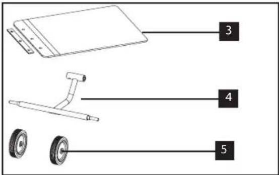
- Plate Compactor Chassis with Engine and Transmission
- Handle
- Paving Pad
- Foldings Wheels Bracket
- Wheels
ÖSSZESZERELÉS
natural_image
Technical line drawing of a mechanical device labeled SGC-8000N, showing lever and base components without any readable text or symbols.natural_image
Technical line drawing of a mechanical lever system with no visible text or symbolsnatural_image
Line drawing of a bicycle handle with a small inset showing the wheel (no text or symbols)natural_image
Technical line drawing of a robotic arm with mounting base and chain, no text or symbols presentRészek listája
natural_image
Technical line drawing of a mechanical device with no visible text or symbolsnatural_image
Line drawing of a kitchen mixer with a bowl of liquid (no text or symbols)natural_image
Line drawing of a manual tiller machine with wheels and a handle, showing no text or symbolsnatural_image
Line drawing of a cleaning or cleaning machine with a downward arrow indicating motion (no text or symbols present)natural_image
Line drawing of a mechanical robotic device with wheels and a head-mounted lever (no text or symbols)Recycle unwanted materials instead of disposing of them as waste. All tools, hoses and packaging should be resorted, taken to the local recycling center and disposed of in an environmentally safe way.
hereby declares the following conformity under the EU Directive and standards for the following article
PL
This appliance is a quality product. It was designed in compliance with current technical standards and made carefully using normal, good quality materials.
The warranty period is 24 months and commences on the date of purchase which can be verified by the receipt, invoice or delivery note. During this warranty period all functional errors, which, despite the careful treatment described in our operating manual, are verifiably due to material laws, will be rectified by our after-sales service staff.
The warranty takes the form that defective parts will be repaired or replaced with perfect parts free of charge at our discretion. Replaced parts will become our property. Repair work or the replacement of individual parts will not extend the warranty period not will it result in a new warranty period being commenced for the appliance. No separate warranty period will
commence for spare parts that may be fitted. We cannot offer a warranty for damage and defects on appliances or their parts caused by the use of excessive force, improper treatment and servicing.
This also applies for failures to comply with the operating manual and the installation or spare and accessory parts that are not included in our range of
products. In the event of interference with of modifications to the appliance by unauthorised persons, the warranty will be rendered void.
Damages that are attributable to improper handling, over loading, or natural wear and tear
are excluded from the guarantee.
Damages caused by the manufacturer or by a material defect will be corrected at no charge by repair or by providing spare parts.
The prerequisite is that the equipment is handed over assembled, and complete with the proof of sale and guarantee.
For a guarantee claim, only use the original packaging.
That way, we can guarantee quick and smooth guarantee processing.
Please send us the appliances post-paid or request a Freeway sticker.
Unfortunately we will be unable to accept appliances that are not postpaid.
The warranty does not cover parts that are subject to natural wear and tear.
If you wish to make a warranty claim, report faults or order spare parts or
accessories, please contact the after-sales centre below:
Subject to change without prior notice.
210 Bath Road; Slough, Berks SL1 3YD
www.stanleytools.co.uk
Tel: +44 (0)1753 511234
Fax: +44 |0|1753 512365

GARANTIE
Purchased at:
in (city, street): ____
Name of customer:
Street address:
Postal code, city: ____
Telephone:
Date, signature:
Fault description:
PL Gwarancja
- Specifications
- G B
- SYMBOLS
- SAFETY
- General Safety Rules
- Understand your Machine
- Work area
- Personal safety
- Fuel safety
- Machine use and care
- Service
- Specific Safety Rules
- CONTENTS SUPPLIED
- ASSEMBLY
- Paving Pad Kit
- Engine Oil
- OIL HAS BEEN DRAINED FOR SHIPPING.
- Part list
- KNOW YOUR MACHINE
- Features and Controls
- Fuel Valve Control
- Throttle Control
- Engine Switch
- Choke Lever
- Recoil Starter Grip
- Exciter
- Compactor Operation
- Adding fuel
- Starting Engine
- Operating
- Do not operate plate on concrete or on extremely hard, dry, compacted surfaces.
- Stopping Engine
- Do not move choke control to CLOSE to stop engine. Backfire or engine damage may occur.
- Idle Speed
- MAINTENANCE
- Preventive Maintenance
- Checking V-Belt(s)
- Tensioning V-Belt
- When adjusting the belt(s), make sure that the clutch pulley is in alignment with exciter pulley.
- When removing or installing the drive belt(s), be careful not to get your fingers caught between the belt and pulley.
- STORAGE
- LIFTING/TRANSPORTING
- ENVIRONMENTAL
- EINFÜHRUNG
- Teileliste
- D
- SAFETY General Safety Rules
- P L
- Seznam dílů
- C Z
- Zoznam dielov
- S K
- Dellista
- KÄNNA DIN MASKIN
- S E
- Motorolje
- OLJEN ER TAPPET UT F∅R SENDING.
- Deleliste
- L∅FTING/TRANSPORT
- NO
- ÖSSZESZERELÉS
- Részek listája
- GARANTIE
- PL Gwarancja
Brand : STANLEY
Model : SGC-8000N
Category : Vibratory plate