CMP-2000 - Multimeter Sonel - Free user manual and instructions
Find the device manual for free CMP-2000 Sonel in PDF.


| Product Type | Digital Clamp Multimeter |
| Model | CMP-2000 |
| Brand | Sonel |
| Display | 6600 counts, 66-segment analog bar graph |
| DC Voltage Range | 0 to 1000 V |
| AC Voltage Range (True RMS) | 0 to 750 V |
| DC Current Range | 0 to 2000 A |
| AC Current Range (True RMS) | 0 to 1500 A |
| Resistance Range | 0 to 66 MΩ |
| Capacitance Range | 0 to 6.6 mF |
| Temperature Range | -20°C to 1000°C (with K-type thermocouple) |
| Frequency Range | 0.01 Hz to 1 MHz |
| Duty Cycle Range | 5% to 95% |
| Continuity Threshold | Less than 30 Ω |
| Auto Power Off | After approx. 30 minutes |
| Power Source | 9V battery (6LR61 or equivalent) |
| Battery Life | Approx. 75 hours (carbon-zinc) |
| Jaw Opening | 57 mm (conductor), 70 x 18 mm (bus bar) |
| Dimensions (H x W x D) | 281 x 108 x 53 mm |
| Weight | Approx. 570 g (including battery) |
| Safety Rating | CAT III 1000V, CAT IV 600V, Class II, IP20 |
| Operating Temperature | 0°C to 50°C |
| Storage Temperature | -20°C to 60°C |
| Accessories Included | Test leads, K-type thermocouple, carrying case, manual |
| Manufacturer | SONEL S.A., Poland |
Frequently Asked Questions - CMP-2000 Sonel
User questions about CMP-2000 Sonel
0 question about this device. Answer the ones you know or ask your own.
Ask a new question about this device
Download the instructions for your Multimeter in PDF format for free! Find your manual CMP-2000 - Sonel and take your electronic device back in hand. On this page are published all the documents necessary for the use of your device. CMP-2000 by Sonel.
USER MANUAL CMP-2000 Sonel

INSTRUKCJA OBSŁUGI 1
USER MANUAL 21
MANUAL DE USO 40
2 Unpacking and inspection 23
3 Safety precautions.... 24
4 Safety information 25
5 Instrument layout.... 26
6 Auto Power off (APO) 29
7 How to make measurements 29
7.1 Voltage measurements....30
7.2 Current measurements....30
7.3 Resistance measurements....31
7.4 Continuity measurements....31
7.5 Diode tests....31
7.6 Capacitance measurements....32
7.7 Temperature measurement 32
7.8 Frequency measurement....32
7.9 % duty cycle measurement 33
8 Replacing the battery 33
9 Cleaning and maintenance 33
10 Storage 34
11 Dismantling and utilisation.... 34
12 Technical data.... 35
12.1 Basic data 35
12.2 Operating data 38
13 Manufacturer 39
1 Introduction
This manual contains information and warnings which must be followed to ensure safe operation and retain the meter in safe condition.
WARNING! Read "Safety information" before using the meter.
This clamp meter is a handheld 6600-count instrument that is designed for use in the laboratory, field servicing, at home, and any circumstance where high current measurement is required. The clamp meter is built with a design of finger guard which ensures users operating the instrument under a safety situation; a rugged case that is shock resistant and fire-retardant; and electronic overload protection for all functions and ranges. In addition, a carrying case (optional accessory) is available for easy portability of the meter and avoiding damage.
2 Unpacking and inspection
Upon removing your new Digital Clamp Meter (DCM) from its packing, you should have the following items:
- Digital clamp meter.
- Test lead set (one black, one red).
- 9-Volt battery (installed in meter).
- Type-K thermocouple.
- Instruction manual.
- Carrying case.
If any of the above items are missing or are received in a damaged condition, please contact the distributor from whom you purchased the unit.
3 Safety precautions
The following safety precautions must be observed to ensure maximum personal safety during the operation, service and repair of this meter:
- Read these operating instructions thoroughly and completely before operating your meter. Pay particular attention to WARNINGS which will inform you of potentially dangerous procedures. The instructions in these warnings must be followed.
- Always inspect your meter, test leads and accessories for any sign of damage or abnormality before every use. If any abnormal conditions exist (broken test leads, cracked cases, display not reading, etc.), do not attempt to take any measurements.
- Do not expose the instrument to direct sun light, extreme temperature or moisture.
- Never ground yourself when taking electrical measurements. Do not touch exposed metal pipes, outlets, fixtures, etc., which might be at ground potential. Keep your body isolated from ground by using dry clothing, rubber shoes, rubber mats, or any approved insulating material.
- To avoid electric shock use CAUTION when working with voltages above 40 V DC or 20 V AC. Such voltages pose a shock hazard.
- Never exceed the maximum allowable input value of any function when taking a measurement. Refer to the specifications for maximum inputs.
- Never touch exposed wiring, connections or any live circuit when attempting to take measurements.
- Do not attempt to operate this instrument in an explosive atmosphere (i.e. in the presence of flammable gases or fumes, vapor or dust).
- When testing for the presence of voltage, make sure the voltage function is operating properly by reading a known voltage in that function before assuming that a zero reading indicates a no-voltage condition. Always test your meter before and after taking measurements on a known live circuit.
- Calibration and repair of any instrument should only be performed by qualified and trained service technicians.
- Remember: Think Safety, Act Safely.
4 Safety information
Cleaning
Wipe the case with a damp cloth and mild detergent. Do not use corrosives or solvents. Dirt or moisture in the terminals can affect readings.
Safety
Conforms to IEC 61010-1 (EN 61010-1), IEC 61010-2-032 (EN 61010-2-032), CAT III 1000 V, CAT IV 600 V, Class II, Pollution degree 2 Indoor use. Degree of housing protection acc. to EN 60529: IP20.
EMC
Conforms to EN 61326-1
The symbols used on this instrument are:
Dangerous voltage
Caution, refer to accompanying documents
☐ Equipment protected throughout by Double insulation (Class II)
\~ Alternating current
--- Direct current
± Ground
5 Instrument layout
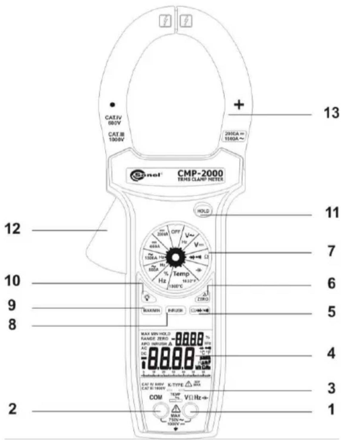
- V Hz% -1←→ Voltage, Ohms, Frequency, % Duty cycle, Capacitance, Diode Input Terminal
This is the positive input terminal for Voltage, Ohms, Frequency, Duty cycle, Capacitance, Diode measurements. Connection is made to it using the red test lead.
- COM Common Terminal
This is the negative (ground) input terminal for all measurement modes except current. Connection is made to it using the black test lead.
- Temperature Input Jacks
Remove test leads and slide TEMP switch to the right to close lead jacks.
- Display
The display indicates the measured value of a signal, function mode, and statement.
- Ω / ⏻ Button
Shift: Ω ⇌ ≈ ≈ ≠ ranges.
- ZERO Button
On the DC current ranges, the ZERO button works as the zero mode. Press ZERO button for more than 2 seconds to exit. On other functions, the ZERO button works as the relative mode. Press REL button again to exit the mode.
In the Relative mode, the value shown on the LCD is always the difference between the stored reference value and the present reading. For example, if the reference value is 24.00 V and the present reading is 12.50 V, the display will indicate -11.50 V. If the new reading is the same as the reference value, the display will be zero.
7. Function/Range selector rotary switch
This rotary switch selects the function, and selects the desired range.
8. INRUSH Button
The INRUSH function captures the starting current precisely in the beginning of 100-millisecond period when current is just started. The INRUSH function is used in the A AC range.
- Press the INRUSH button to toggle in the INRUSH mode, and the "----" and "INRUSH" will be displayed.
- Press the trigger to open transformer jaws and clamp onto single conductor only, and turn on the meter.
- Read the INRUSH current directly from the display.
- Depress the INRUSH button for more than 2 second to exit the INRUSH mode.
- Minimum input range: >100 dgts.
- The readings of INRUSH measurements will show on the sub-display.
- Sampling frequency is 6x/100 ms (60 Hz).
9. MAX/MIN Button
The "MAX" displays the maximum value of measurements. The "MIN" displays the minimum value of measurements. Press MAX/MIN button for more than 2 seconds to exit. The recorded value of MAX/MIN function will show on the sub-display, and the value being measured will show on the main-display.
10. Backlight Button
Press the button to activate the backlight for approximately 60 second.
11. HOLD Button
Press HOLD button to toggle in and out of the Data Hold mode. In the data hold mode, the "HOLD" statement is displayed and the last reading is held on the display. Press HOLD button again to release the hold and current readings are once again displayed.
12. Trigger
Press the lever to open the transformer. When the lever is released, the jaws will close again.
13. Transformer jaws
Pick up the AC or DC current flowing through the conductor. The "+" marking on the jaw indicates direction of DC current existing on the conductor being tested which follows forward and vertically with jaws, and reading shown on display is positive.
6 Auto Power off (APO)
Auto Power off: approx. 30 minutes. The meter will generate sounds before power off.
After auto power off, press any button to restart the meter, and the reading of measurement will be maintained in the display.
Cancellation Of Auto Power Off Feature: Press and hold the (MAX/MIN) button while rotating function switch from off to any position to turn the meter on. The auto power off feature is disabled. "APO" statement is missing from the LCD.
7 How to make measurements
Before making any measurements read safety precautions. Always examine the instrument and accessories used with the instrument for damage, contamination (excessive dirt, grease, etc.) and defects. Examine the test leads for cracked or frayed insulation and make sure the lead plugs fit snugly into the instrument terminals. If any abnormal conditions exist, do not attempt to make any measurements.
7.1 Voltage measurements
- Set the Function/Range switch to the V\~/V position.
WARNING!
To avoid possible electric shock, instrument damage and / or equipment damage, do not attempt to take any voltage measurements if the voltage is above 1000 V DC / 750 V AC. 1000 V DC and 750 V AC are the maximum voltages that this instrument is designed to measure.
- Plug the black test lead into the "COM" input jack on the meter.
- Plug the red test lead into the "VΩ" input jack on the meter. Voltage is always measured in parallel across a test point.
- Connect the test leads to the circuit /device to be measured and make the voltage measurement.
- After completing the measurement disconnect the meter test leads.
7.2 Current measurements
WARNING!
These Snap-Arounds are designed to take current measurements on circuits with a maximum voltage difference of 1000 V DC / 750 V AC between any conductor and ground potential. Using the Snap-Around for current measurements on circuits above 1000 V DC / 750 V AC may cause electric shock, instrument damage and/or damage to the equipment under test. Before measuring current make certain that the test leads are removed from the instrument.
Do not take current readings on circuits where the maximum current potential is not known. Do not exceed the maximum current that this instrument is designed to measure.
- Set the Function/Range switch to the A\~/A -position.
- Press the trigger to open the transformer jaws and clamp them around a conductor. Jaws should be completely closed before taking a reading.
- The most accurate reading will be obtained by keeping the conductor across center of the transformer jaws.
- The reading will be indicated on the main display.
- Reduce the range setting if set too high until a satisfactory best resolution reading is obtained.
7.3 Resistance measurements
- Set the Function/Range switch to the " " position.
- Turn off power to the circuit under test. External Voltage across the components causes invalid reading
- Connect the red test lead to the "VΩ" jack and the black test lead to the „COM" jack.
- Connect the test leads to the points of measurements and read the value from the display.
7.4 Continuity measurements
- Set the Function/Range switch to the ●●●● position. Use the Ω/●●● to select the continuity test.
- Turn off power to the circuit under test. External Voltage across the components causes invalid reading.
- Connect the red test lead to the "VΩ" jack and the black test lead to the „COM" jack.
- Connect the test leads to the two points at which continuity is to be tested. The buzzer will sound if the resistance is less than approximately 30 Ω.
7.5 Diode tests
- Set the Function/Range switch to the position. Use the /10 button twice to select the diode test.
- Turn off power to the circuit under test. External voltage across the components causes invalid readings.
-
Connect the red test lead to the "VΩ" jack and the black test lead to the „COM" jack.
-
Touch probes to the diode. A forward-voltage drop is about 0.6 V (typical for a silicon diode).
- Reverse probes. If the diode is good, "OL" is displayed. If the diode is shorted, "0.00" or another number is displayed.
- If the diode is open, "OL" is displayed in both directions.
- Audible Indication: Less than 0.03 V.
7.6 Capacitance measurements
- Set the Function/Range switch to the " " position.
- Connect the red test lead to the "VΩ" jack and the black test lead to the "COM" jack.
- Discharge the capacitor before taking capacitance measurements.
- Touch the probes to the capacitor. Observe polarity when measuring polarized capacitors.
- Read the capacitance directly from the display.
- The meter has a residual capacitance in the 6.6 nF and 660 nF ranges, which is a normal status. Before taking measurements, press the ZERO button to zero the residual capacitance.
- When the capacitor to be tested is connected, if "dIS.C" symbol indicates on LCD, it means there is voltage existing in the tested capacitor and to be discharged before testing.
7.7 Temperature measurement
- Set the Function/Range switch to the "Temp" position.
- Remove leads and slide TEMP switch to the right to close lead jacks.
- Plug K-type thermocouple directly into the meter to measure temperature.
- Take temperature measurement using the thermocouple probe and read the temperature from the display.
7.8 Frequency measurement
- Set the Function/Range switch to the „Hz/%” position.
- Connect the red test lead to the "VΩ" jack and the black test lead to the "COM" jack.
- Connect the test leads to the point of measurement and read the frequency from the main display.
7.9 % duty cycle measurement
- Set the Function/Range switch to the „Hz/%" position.
- Connect the red test lead to the "VΩ" jack and the black test lead to the "COM" jack.
- The readings of \% duty cycle measurements will show on the sub-display.
8 Replacing the battery
WARNING!
To avoid electrical shock, disconnect the test leads and any input signals before replacing the battery. Replace only with same type of battery.
This meter is powered by a 6LR61 (or 6F22, NEDA type 1604 or equivalent 9-volt battery). When the meter displays the battery must be replaced to maintain proper operation. Use the following procedure to replacing the battery:
- Disconnect test leads from any live source, turn the rotary switch to OFF, and remove the test leads from the input terminals.
- The battery cover is secured to the bottom case by a screws. Using a Phillips-head screwdriver, remove the screws from the battery cover and remove the battery cover.
- Remove battery and replace with a new equivalent 9-volt battery.
- Replace the battery cover and reinstall the screws.
9 Cleaning and maintenance
ATTENTION!
Use only the maintenance methods specified by the manufacturer in this manual.
The casing of the meter may be cleaned with a soft, damp cloth using all-purpose detergents. Do not use any solvents or cleaning agents which might scratch the casing (powders, pastes, etc.).
Clean the probe with water and dry it. Before the probe is stored for a prolonged period of time it is recommended to grease it with any machine lubricant.
The reels and test leads should be cleaned with water and detergents, and then dried.
The electronic system of the meter does not require maintenance.
10 Storage
In the case of storage of the device, the following recommendations must be observed:
- Disconnect all the test leads from the meter.
- Clean the meter and all its accessories thoroughly.
• Wind the long test leads onto the reels. - In the case the meter is to be stored for a prolonged period of time, the batteries must be removed from the device.
- In order to prevent a total discharge of the rechargeable batteries in the case of a prolonged storage, charge them from time to time.
11 Dismantling and utilisation
Worn-out electric and electronic equipment should be gathered selectively, i.e. it must not be placed with waste of another kind.
Worn-out electronic equipment should be sent to a collection point in accordance with the law of waste electrical and electronic equipment.
Before the equipment is sent to a collection point, do not dismantle any elements.
Observe the local regulations concerning disposal of packages and used batteries/rechargeable batteries.
12 Technical data
12.1 Basic data
Accuracy is given as
±([% of reading]+[number of least significant digits]) at 18°C to 28°C, with relative humidity up to 70%.
DC Voltage
| Range | Resolution | Accuracy |
| 0.000...6.599 V | 0.001 V | ±(0.5% rdg + 2d) |
| 6.60...65.99 V | 0.01 V | |
| 66.0...659.9 V | 0.1 V | |
| 660...1000 V | 1 V |
- Input impedance: ≥9 MΩ
• Overload protection: 1000 V DC or 750 V AC RMS.
AC Voltage (True RMS)
| Range | Resolution | Accuracy |
| 0.000...6.599 V | 0.001 V | ±(1.5% rdg + 8d)50...500 Hz |
| 6.60...65.99 V | 0.01 V | |
| 66.0...659.9 V | 0.1 V | |
| 660...750 V | 1 V |
• Input impedance: ≥8.5 MΩ
- Crest Factor: ≤ 3 .
• AC coupled true RMS specified from 5% to 100% of range.
- Frequency ranges: 50 Hz \~ 1 kHz. Accuracy of f: ±(0.1% rdg + 5 dgts). The readings of frequency measurements will show on the sub-display.
• Minimum Input voltage Range: >500 dgts.
• Overload protection: 1000 V DC or 750 V AC RMS.
AC current (True RMS)
| Range | Resolution | Accuracy | ||
| 660 A | 0.1 A | 0...660 A | ±(2.0% rdg + 10d) | 50...60 Hz |
| 0...660 A | ±(3.0% rdg + 10d) | 61...400 Hz | ||
| 1500 A | 1 A | 660...1000 A | ±(2.5% rdg + 10d) | 50...60 Hz |
| 660...1000 A | ±(3.5% rdg + 10d) | 61...400 Hz | ||
| 1000...1500 A | ±(5.0% rdg + 10d) | 50...400 Hz | ||
- Crest Factor: ≤ 3 .
• AC coupled true RMS specified from 5% to 100% of range.
- Frequency ranges: 50 Hz \~ 1 kHz. Accuracy: ±(0.1% rdg + 5 dgts). The readings of frequency measurements will show on the sub-display.
• Minimum Input current Range: >500 dgts.
• Overload protection: 1500 A AC.
DC current
| Range | Resolution | Accuracy | |
| 660 A | 0.1 A | 0...660 A | ±(2.0% rdg + 5d) |
| 2000 A | 1 A | 660...1000 A | ±(3.0% rdg + 5d) |
| 1000...2000 A | ±(5.0% rdg + 5d) | ||
• Overload protection: 2000 A DC for 60 seconds maximum.
Resistance
| Range | Resolution | Accuracy | Open Circuit Voltage |
| 660 Ω | 0.1 Ω | ±(1.0% rdg + 5d) | -3.2 V DC |
| 6.6 kΩ | 1 Ω | ±(1.0% rdg + 5d) | -1.1 V DC |
| 66 kΩ | 10 Ω | ±(1.0% rdg + 5d) | -1.1 V DC |
| 660 kΩ | 100 Ω | ±(1.0% rdg + 5d) | -1.1 V DC |
| 6.6 MΩ | 1 kΩ | ±(2.0% rdg + 5d) | -1.1 V DC |
| 66 MΩ | 10 kΩ | ±(3.5% rdg + 5d) | -1.1 V DC |
• Overload protection: 600 V DC or AC RMS.
Continuity test
| Range | Audible Threshold | Response Time | Open Circuit Voltage |
| 660 Ω | Less than 30 Ω | Approx. 100 ms | -3.2 V DC |
Diode test
| Range | Resolution | Accuracy | Test Current | Open Circuit Voltage |
| 2 V | 1 mV | ±(1.5% rdg + 5d) | 0.8 mA | 3.2 V DC typical |
Capacitance
| Range | Resolution | Accuracy |
| 6.6 nF | 1 pF | ±(3.0% rdg + 30d) |
| 66 nF | 10 pF | ±(3.0% rdg + 10d) |
| 660 nF | 100 pF | ±(3.0% rdg + 30d) |
| 6.6 μF | 1 nF | ±(3.0% rdg + 10d) |
| 66 μF | 10 nF | ±(3.0% rdg + 10d) |
| 660 μF | 100 nF | ±(3.0% rdg + 10d) |
| 6.6 mF | 1 μF | ±(5.0% rdg + 10d) |
• Overload Protection: 600 V DC or AC RMS.
Temperature
| Range | Resolution | Accuracy | Sensor type |
| 0...400°C | 1°C | ±(1.0% rdg + 2°C) | K-type thermo-couple |
| -20...0°C. 400...1000°C | 1°C | ±(2.0% rdg + 3°C) | |
| 32...750°F | 1°F | ±(1.0% rdg + 4°F) | |
| -4...32°F. 750...1832°F | 1°F | ±(2.0% rdg + 6°F) |
• Overload protection: 60 V DC or 30 V AC RMS.
Frequency
| Range | Resolution | Accuracy | Trigger Level |
| 66 Hz | 0.01 Hz | ±(0.1% rdg + 5d) | >3.2 V |
| 660 Hz | 0.1 Hz | ±(0.1% rdg + 5d) | >3.2 V |
| 6.6 kHz | 1 Hz | ±(0.1% rdg + 5d) | >3.2 V |
| 66 kHz | 10 Hz | ±(0.1% rdg + 5d) | >3.2 V |
| 660 kHz | 100 Hz | ±(0.1% rdg + 5d) | >3.2 V |
| 1 MHz | 1 kHz | ±(0.1% rdg + 5d) | >3.2 V |
• Minimum Input Range: >10 Hz.
• Minimum pulse width: >1 s.
• Duty cycle limits: >30% and <70%.
• Overload protection: 600 V DC or AC RMS.
% Duty Cycle
| Range | Resolution | Pulse width | Accuracy (5 V logic) |
| 5...95% | 0.1% | >10 μs | ±(2.0% rdg + 10d) |
• Frequency range: 5% to 95% (40 Hz to 20 kHz).
- The readings of % duty cycle measurements will show on the sub- display.
• Overload protection: 600 V DC or AC RMS.
12.2 Operating data
a) Display 6600 counts, 66 segments analog bar-graph
b) Polarity ....automatic, (-) negative polarity indication
c) Overrange Indication ....OL or -OL
d) Low Battery Indication ....the is displayed ....when the battery voltage drops below accurate operating level
e) Measurement Rate 2.8x/sec, nominal. 28x/sec, analog bar-graph
f) Operating Environment 0°C to 50°C at <70% R.H
g) Storage Environment ....-20°C to 60°C at <80% R.H
h) Temperature Coefficient ....0.1 x (specified accuracy) / °C (<18°C or >28°C)
i) Auto Power Off ....30 minutes after rotary switch or mode changes
j) Altitude 2000 m
k) Power ...... Standard 9-volt battery
I) Battery Life 75 hours typical with carbon-zinc battery
m) Jaw Opening Capability ....57 mm conductor ....70 x 18 mm bus bar
n) Size (H x W x D) 281 x 108 x 53 mm
o) Weight Approx. 570 grams (including battery)
13 Manufacturer
The manufacturer of the device and provider of guarantee and post-guarantee service:
SONEL S.A.
Wokulskiego 11
58-100 Świdnica
Poland
tel. +48 74 884 10 53 (Customer Service)
e-mail: customerservice@sonel.com
web page: www.sonel.com
Note:
Service repairs must be performed only by the manufacturer.

MANUAL DE USO
MEDIDOR DE PINZA DIGITAL AC/DC
CMP-2000
CE
- Introduction
- WARNING! Read "Safety information" before using the meter.
- Unpacking and inspection
- Safety precautions
- Safety information
- Cleaning
- Safety
- EMC
- The symbols used on this instrument are:
- Function/Range selector rotary switch
- INRUSH Button
- MAX/MIN Button
- Backlight Button
- HOLD Button
- Trigger
- Transformer jaws
- Auto Power off (APO)
- How to make measurements
- Voltage measurements
- WARNING!
- Current measurements
- Resistance measurements
- Continuity measurements
- Diode tests
- Capacitance measurements
- Temperature measurement
- Frequency measurement
- % duty cycle measurement
- Replacing the battery
- Cleaning and maintenance
- ATTENTION!
- Storage
- Dismantling and utilisation
- Technical data
- Basic data
- DC Voltage
- AC Voltage (True RMS)
- Operating data
- Manufacturer
- MANUAL DE USO
- MEDIDOR DE PINZA DIGITAL AC/DC
Brand : Sonel
Model : CMP-2000
Category : Multimeter