
M3691 - Multimeter Emos - Free user manual and instructions
Find the device manual for free M3691 Emos in PDF.


| Product Type | Digital Multimeter |
| Brand | Emos |
| Model | M3691 |
| Dimensions (approx.) | 150 x 70 x 30 mm |
| Weight (approx.) | 200 g |
| Power Supply | 9V battery (6F22 or equivalent) |
| Display | LCD, 3½ digits (2000 counts) |
| DC Voltage Range | 200 mV - 600 V |
| AC Voltage Range | 200 V - 600 V |
| DC Current Range | 200 µA - 10 A |
| Resistance Range | 200 Ω - 2 MΩ |
| Additional Functions | Continuity test, diode test, transistor hFE test |
| Safety Rating | CAT II 600 V |
| Overload Protection | Fuse for current ranges |
| Maintenance | Clean with a dry cloth; do not use solvents |
| Spare Parts / Repairability | Test leads, battery, fuse (replaceable) |
| Accessories Included | Test leads, battery, user manual |
Frequently Asked Questions - M3691 Emos
User questions about M3691 Emos
0 question about this device. Answer the ones you know or ask your own.
Ask a new question about this device
Download the instructions for your Multimeter in PDF format for free! Find your manual M3691 - Emos and take your electronic device back in hand. On this page are published all the documents necessary for the use of your device. M3691 by Emos.
USER MANUAL M3691 Emos
Carefully read through this instruction manual before you begin using the MD-410. It contains particularly important passages concerning occupational safety principles when using the device. Such passages are highlighted. Reading the manual will prevent potential injury by electric current or damage to the device. The multimeter was designed in accordance with the IEC-61010 standard regarding electronic measuring devices in the category (CAT III 300 V), 2nd degree of pollution. The CAT III category is used to measure circuits powered by a fixed output power supply, such as a relay, socket, switchboards, power supplies and short branching circuits and lighting systems in large buildings.

Warning
Use the MD-410 multimeter only in the manner specified below. Other uses may cause damage to the device or injury to your health.
Comply with the following instructions:
- Before measuring resistance, diodes or current, disconnect the circuits from the power supply and discharge high-voltage capacitors. Use the corresponding function for the given measurement. Before changing the range (of a function) disconnect the conductor from the circuit being measured.
- Make sure the device is not damaged before you begin using the multimeter. If you find obvious signs of damage on the body of the device, do not perform any measurements! Check that the surface of the multimeter does not have scratches and that the side joints are not coming apart.
- Also check the insulation on the measuring probes. Damaged insulation may result in injury by electric current. Do not use damaged measuring probes!
- Do not measure voltages above 300 V! If you will be measuring the current, check the multimeter's fuse and turn off the power supply to the circuit before you connect the multimeter. Before measuring make sure the circular switch for the measuring range is in the correct position. Under no circumstances should you make any changes in the measuring range (by moving the circular switch for measuring programs) when measuring! It could lead to device damage. When you are measuring, connect the black conductor (probe) first and then the red conductor (probe). When disconnecting the testing conductors, disconnect the red one first.
- If you find that the meter is registering abnormal measurements, stop using it. The fuse may be damaged. If you are unsure of the cause of the defect, contact a service centre.
- Do not measure voltages higher than the one indicated on the front panel of the multimeter. Risk of injury by electric current or damage to the multimeter!
- Check that the multimeter is working properly before use. Test on a circuit with electrical values you know.
- Before you connect the multimeter to a circuit you intend to measure, turn off the power to the circuit.
- Do not use or store the multimeter in environments with high temperature, dust or humidity. It is also not recommended to use the device in environments with potentially strong magnetic fields or risk of explosion or fire.
- When changing parts of the multimeter (e.g. the battery or fuse) use spare parts of the same type and specifications. Change parts only when the multimeter is disconnected and turned off. Do not change the 10 A/300 V fuse by yourself, please contact a service centre. Disconnect the testing conductors from the tested circuit before opening the rear casing of the device.
- Do not alter or otherwise interfere with the internal circuitry of the multimeter!
- Please be careful when measuring voltages higher than 30 V AC rms, 42 V peak or 60 V DC. There is a risk of injury resulting from electric shock!
- When using measuring tips, make sure you are holding them behind the finger barriers.
- Do not perform measurements if the multimeter's casing is removed or loose.
- Change the batteries when an icon of a discharged battery appears “☐”. In case you do not do so, the following measurements may not be precise. Incorrect measurements may then result in injuries by electric current! Use only alkaline batteries, do not use re-chargeable batteries.
Maintenance Instructions
Warning
Do not attempt to repair or modify the multimeter in any way if you are not qualified to do so or do not have access to the necessary calibration equipment. Make sure that water does not get into the multimeter – you could prevent injury by electric current!
- Disconnect the measuring tips from the tested circuit before opening the casing of the multimeter.
- Regularly clean the body of the multimeter with a moist cloth and a mild detergent. Perform cleaning only when the multimeter is disconnected and turned off.
- Do not use solvents or abrasive agents for cleaning!
- If you haven't been using the multimeter for a longer period of time, turn it off and remove the batteries.
- Do not store the multimeter in places with high humidity and temperature or in environments with strong magnetic fields!
Changing batteries
When the "symbol" appears on the display, this means the battery is low and must be immediately changed.
To replace the batteries, unfasten the screw at the rear of the casing and remove the casing. Change the discharged battery for a new one of the same type (9 V, 6F22 type or equivalent) and adhere to the correct polarity of the placed battery. Replace the rear casing.
Electrical Symbols
\~ Alternating current (AC)
--- Direct current (DC)
≈ Alternating current and direct current (AC/DC)
Warning symbol, hazard. Pay particular attention to sections of the manual marked with this symbol.

Risk of injury by electric current

Fuse

Earthing

Double insulation

The product complies with the applicable EU standards
Device description
MD-410 is a compact 3 ½ numerical digital multimeter with a manual measuring range of DC and AC voltage, DC and AC current, contactless detection of AC voltage, resistance, continuity and diode testing. (see Fig. 1)
1 - Screen
2 - Button for changing between measuring alternating or direct voltage/current

3 - Button for contactless alternating voltage detection
4 - Button "for display backlight
5 - Circular switch for measuring range/choosing the required function
6 - "10 A" socket - for the end of the red (positive) measuring conductor with the tip for measuring currents in a range of 10 A AC/DC
7 - "COM" socket - for the end of the red (positive) measuring conductor with a tip
8 - "VΩmA °C" socket - for the end of the red (positive) measuring conductor with a tip for measuring voltage, resistance, diodes, continuity, temperature and current up to 200 mA.
9 – Button for activating the flashlight
10 - LED diode signaling the AC voltage in the contactless detection mode
11 - Hutton - DATA HOLD function
12 - protective case
13 - flashlight's LED diode
Technical Information
Screen: 3 ½ digit LCD with a maximum displayable value of 1999
Negative polarity indication: " - " will automatically appear on the display
Overload indication: "OL" or will appear on the display
Reading frequency: approximately 2× to 3× per second
Temperature measurement range: 0 °C up to 1 000 °C (0 °C to 250 °C with the temperature probe attached)
Power supply: 1×9 V battery, 6F22 type or equivalent
Operating temperature: 0 °C to 40 °C, relative humidity < 75 %
Storage temperature: -10 °C to 50 °C, relative humidity < 85 %
Dimensions: 170 × 86 × 40 mm
Weight: 290 g including battery
Measurement Accuracy
Accuracy is specified for the duration of one year after calibration and only at temperatures between 18 °C and 28 °C and air humidity up to 75 %.
Accuracy specifications are:
± [(%% of reading) + (lowest valid digits)]
DC Voltage
| Range Resolution Accuracy | ||
| 200 mV 100 μV ± (0.5 % + 5) | ||
| 2 V 1 mV | ± (0.8 % + 5)20 V 10 mV | |
| 200 V | 100 mV | |
| 300 V | 1 V | ± (1 % + 5) |
Input impedance: 10 MΩ
⚠️ Maximum input voltage: 300 V DC
AC Voltage
| Range Resolution | Accuracy | |
| 200 mV 100 μV ± (1 % + 5) | ||
| 2 V 1 mV | ± (1.2 % + 5) | |
| 20 V 10 mV | ||
| 200 V 100 mV | ||
| 300 V 1 V | ||
Frequency range: 40 Hz to 400 Hz
△ Maximum input voltage: 300 V AC
Response: average value, corresponding to a calibrated effective value of a sine wave.
Direct current (DC)
| Range Resolution Accuracy | |
| 20 mA 10 μA ± (1 % + 5) | |
| 200 mA 100 μA ± (1.5 % + 5) | |
| 10 A 10 mA ± (2 % + 5) |
Protection against overload:
range μA a mA: fuse 250 mA/300 V, type F, ∅ 5 × 20 mm.
range 10 A: fuse 10 A/300 V, type F, ∅ 5 × 20 mm.
Maximum input voltage: "VΩmA" socket max 200 mA; "10 A" socket max 10 A (when measuring currents larger than 2 A; the measuring duration can be max. 10 seconds and measuring may be repeated again only after 15 minutes)
Alternating current (AC)
| Range Resolution Accuracy | |
| 20 mA 10 μA ± (1.3 % + 5) | |
| 200 mA 100 μA ± (1.8 % + 5) | |
| 10 A 10 mA ± (3 % + 5) |
Protection against overload:
μA and mA range: fuse 250 mA/300 V, type F, ∅ 5 × 20 mm.
10 A range: fuse 10 A/300 V, type F, ∅ 5 × 20 mm.
Maximum input current: "VΩmA" socket max. 200 mA; "10 A" socket max. 10 A (when measuring currents larger than 2 A; the measuring duration must be max. 10 seconds and measuring may be repeated again only after 15 minutes)
Frequency range: 40 Hz to 400 Hz
Response: average value, corresponding to a calibrated effective value of a sine wave.
Resistance
| Range Resolution Accuracy | |
| 200 Ω 0.1 Ω | |
| 2 kΩ 1 Ω | |
| 20 kΩ 10 Ω | |
| 200 kΩ 100 Ω | |
| 2M Ω 1 kΩ | |
| 20 MΩ 10 kΩ ± (1.5 % + 7) |
Voltage of an open circuit: 2.8 V
Battery test
| Range Resolution Electrical load | |
| 1.5 V 0.001 V approximately 20 mA | |
| 9 V 0.01 V approximately 5 mA | |
| 12 V 0.01 V approximately 4 mA |
Continuity test
| Symbol | Description Note | |
| The in-built buzzer will ring constantly if the resistance is lower than 20 Ω.The buzzer will be quiet if the resistance is higher than 100 Ω.If the resistance is between 20 Ω and 100 Ω, the buzzer can, but may not ring. | Voltage of an open circuit: approximately 2.8 V |
Diode test
| Symbol | Description Note | |
| The approximate voltage of the diode in the open state will appear on the display | Voltage of an open circuit: approximately 2.8 VLoad current: approximately 1 mA |
Measuring temperature
| Range Resolution | Accuracy | |
| 0 °C to 400 °C | 1 °C | ± (1 % + 5) |
| 400 °C to 1 000 °C ± (2.5 % + 10) |
The accuracy stated for the surrounding temperature stability ± 1^ .
Measuring out of the range could cause damage to the temperature probe and a large variance in accuracy.
DATA HOLD function
After pressing the H button the current registered value will stay on the display and an icon will appear on the display: H Pressing the button again will stop the function and the icon will disappear.
Display backlight
After pressing the ✪ button the display will be backlit for approx. 25 seconds, it will then automatically turn off. You may also turn off the backlight by repeatedly pressing the ✪ button.
Operating Procedure
AC voltage/DC voltage measurement function
Connect the end bit of the black (negative) measuring conductor with the tip into the "COM" socket and the end bit of the red (positive) for measuring voltage into the "VΩmA" socket. Switch to the function marked with a ≈ V. Choose measuring direct and alternating voltage with the DC button. Choose the measuring range and connect the measuring tips to the place where you will measure voltage. The voltage value will display along with its polarity (for DC voltage). If you do not know the voltage range beforehand, set the largest possible range and gradually decrease it. Connect the measuring tips to the device or circuit where you will be measuring the voltage. Turn on the power to the device you will be measuring. The voltage value will appear on the display.
Note: To prevent electric shock and damaging the device, do not connect voltage higher than 300 V to the multimeter.
AC voltage/DC voltage measurement function
Note: The 10 A socket is permanently inaccessible and only temporarily accessible when setting a 10 A range! It is not possible to move the circular switch if the red (positive) conductor is connected to the 10 A socket.
When measuring currents up to 200 mA connect the end bit of the black (negative) measuring conductor with the tip into the "COM" socket and the end bit of the red (positive) for measuring voltage into the "VΩmA" socket.
Switch to the function marked with a ≈A. Using the button select direct or alternating current. When measuring current up to 10 A first select the 10 A measuring range and then connect the end bit of the black (negative) measuring conductor with a tip into the "COM" socket and the end bit of the red (positive) for measuring voltage into the "10 A" socket. If you do not know the current range beforehand, set the highest range possible and gradually lower it. Connect the measuring tips to the device or circuit where you will measure the current. Turn on the device you want to measure. The value of the current will appear on the display and its respective polarity from the red measuring tip (for DC currents).
Continuity test
Connect the end bit of the black (negative) measuring conductor with the tip into the "COM" socket and the end bit of the red (positive) for measuring voltage into the "VΩmA" socket. Switch to the function marked with a .) Connect the measuring tips to the circuit being measured. The buzzer will ring if the resistance of the measured circuit is lower than 20 Ω.
Note: Before testing disconnect all the power supplies to the circuit you wish to test and thoroughly discharge all capacitors.
Resistance Measurement Function
Connect the end bit of the black (negative) measuring conductor with the tip into the "COM" socket and the end bit of the red (positive) for measuring voltage into the "VΩmA" socket. Switch to the function marked with a Ω. Choose the measuring range. It is necessary to switch to a higher range if the "OL" symbol appears on the display. Connect the measuring tips to the object being measured (resistance). The resistance value registered will appear on the display. When measuring resistances with a value higher than 1 MΩ it is necessary to wait a few seconds before the measured value stabilizes. If the circuit is not closed the "OL" symbol will appear, as when exceeding the range. Before making measurements, disconnect the power supply from the tested circuit and thoroughly discharge all its capacitors.
Measuring diodes function
Connect the end bit of the black (negative) measuring conductor into the "COM" socket and the end bit of the red (positive) measuring tip for measuring diodes into the "VΩmA" socket. Switch to the function marked with a Connect the red measuring tip onto the anode diode and the black measuring tip onto the cathode diode. Approximate voltage in the open state will appear on the display. When switching polarities "OL" will appear on the display.
Testing batteries function
Connect the black (negative) measuring conductor into the "COM" socket and the red (positive) measuring tip for measuring diodes into the "VΩmA" socket. Switch to the BA function and choose the measuring range according to the type of battery. Connect the measuring tips to the battery in such a way that the red tip is connected to the positive pole and the black to the negative pole of the battery. The values measured will appear on the display.
Note: When finished measuring disconnect the measuring tips from the battery being tested.
Measuring temperature
- Choose the °C with the circular switch.
- Connect the black end bit (minus) to the COM socket and the red end bit (plus) of the type K temperature probe into the VΩmA socket.
- Carefully place the end of the temperature probe onto the measured object. The object can not be turned on and beware of the device's parts that rotate. After a while the measured temperature will appear on the display.

Note:
The type K temperature probe which is part of the multimeter is made for measuring a temperature range from 0 °C to 250 °C.
Damage may occur to the probe and multimeter when measuring temperatures higher than 250 °C!
Use the corresponding temperature probe with a larger measuring range if you want to measure a higher temperature!
Contactless AC voltage detection / phase conductor detection
- Long press the button for contactless AC voltage detection (on the picture on the right).
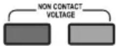
The buzzer will ring twice and the red diode will flash twice.
- Bring the top part of the multimeter close to the object you want to detect. If the multimeter detects AC voltage then the in-built buzzer will ring intermittently and a red detection diode will flash (on the image on the right).
Warning
- Voltage outside of the multimeter's range will not be detected.
- Due to the detection limit on the multimeter the link or conductor being tested may be active, even if the in-built buzzer doesn't sound. To prevent electric shock do not touch the conductors.
- Before use disconnect all of the testing conductors from the multimeter and confirm the multimeter's function by detecting known AC voltage.
In the same way you may detect a phase conductor by using attached probes.
Connect the end bit of the black (negative) measuring conductor with a tip into the "COM" socket or the end bit of the red (positive) for measuring voltage into the "VΩmA" socket. Long press the button for contactless AC voltage detection. Connect the measuring tip to the object being measured. If the multimeter detects a phase conductor, the in-built buzzer will ring intermittently and the diode will be flashing.
Do not dispose with domestic waste. Use special collection points for sorted waste. Contact local authorities for information about collection points. If the electronic devices would be disposed on landfill, dangerous substances may reach groundwater and subsequently food chain, where it is affected by human health.
Emos spol s.r.o. declares that the MD-410 is in compliance with the essential requirements and other relevant provisions of Directive. The device can be freely operated in the EU. The Declaration of Conformity can be found at http://www.emos.eu/download.
13 – LED dioda svítilny
Technické info
Mjerenje temperature
| Područje Rezolucija | Točnost | |
| 0 °C do 400 °C | 1 °C | ± (1 % + 5) |
| 400 °C do 1.000 °C | ± (2,5 % + 10) |
Navedena točnost je za stabilnost okolne temperature ±1 °C. Mjerenje izvan navedenog područja može dovesti do oštećenja temperaturne sonde i velike varijacije u točnosti.
Funkcija DATA HOLD
Nakon pritiska na gumb H, trenutno prikazana vrijednost se zadržava na zaslonu, a na zaslonu se pojavljuje ikona: H. Ponovnim pritiskom na taj gumb funkcija se prekida i ikona nestaje.
Mjerenje temperature
- Kružni preklopnik postavite na položaj °C.
- Priključite kraj crnog vodiča (negativnog) na COM utičnicu, a kraj crvene (pozitivne) temperaturne sonde tipa K u utičnicu VΩmA.
- Pažljivo postavite vrh temperaturne sonde na predmet koji mjerite. Predmet ne smije biti uključen, a pripazite i na eventualne dijelove koji rotiraju. Nakon nekog vremena izmjerena temperatura pojavljuje se na zaslonu.

Napomena:
Temperaturna sonda tipa K koja je dio multimetra, napravljena za mjerenje temperatura od 0 °C do 250 °C. Ako se mjere temperature više od 250 °C, može doći do oštećenja sonde i multimetra! Ako želite mjeriti više temperature, koristite odgovarajuću temperaturnu sondu većeg mjernog raspona!
Bezkontaktno otkrivanje izmjeničnog napona / faznog vodiča
- Držite pritisnut gumb za bezkontaktno otkrivanje izmjeničnog napona (desno na slici).
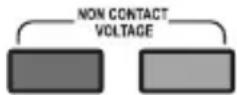
--- Curent continuu (DC)


- Warning
- Maintenance Instructions
- Changing batteries
- Electrical Symbols
- Device description
- Technical Information
- Measurement Accuracy
- DATA HOLD function
- Display backlight
- Operating Procedure
- AC voltage/DC voltage measurement function
- Continuity test
- Resistance Measurement Function
- Measuring diodes function
- Testing batteries function
- Measuring temperature
- Contactless AC voltage detection / phase conductor detection
- Technické info
- Funkcija DATA HOLD
- Mjerenje temperature
- Napomena:
- Bezkontaktno otkrivanje izmjeničnog napona / faznog vodiča
Brand : Emos
Model : M3691
Category : Multimeter